WO2016108273A1 - 透明スクリーン、及び透明スクリーンの製造方法 - Google Patents
透明スクリーン、及び透明スクリーンの製造方法 Download PDFInfo
- Publication number
- WO2016108273A1 WO2016108273A1 PCT/JP2015/086009 JP2015086009W WO2016108273A1 WO 2016108273 A1 WO2016108273 A1 WO 2016108273A1 JP 2015086009 W JP2015086009 W JP 2015086009W WO 2016108273 A1 WO2016108273 A1 WO 2016108273A1
- Authority
- WO
- WIPO (PCT)
- Prior art keywords
- transparent screen
- regular hexagonal
- transparent
- thin film
- screen
- Prior art date
- Legal status (The legal status is an assumption and is not a legal conclusion. Google has not performed a legal analysis and makes no representation as to the accuracy of the status listed.)
- Ceased
Links
Images


Classifications
-
- G—PHYSICS
- G03—PHOTOGRAPHY; CINEMATOGRAPHY; ANALOGOUS TECHNIQUES USING WAVES OTHER THAN OPTICAL WAVES; ELECTROGRAPHY; HOLOGRAPHY
- G03B—APPARATUS OR ARRANGEMENTS FOR TAKING PHOTOGRAPHS OR FOR PROJECTING OR VIEWING THEM; APPARATUS OR ARRANGEMENTS EMPLOYING ANALOGOUS TECHNIQUES USING WAVES OTHER THAN OPTICAL WAVES; ACCESSORIES THEREFOR
- G03B21/00—Projectors or projection-type viewers; Accessories therefor
- G03B21/54—Accessories
- G03B21/56—Projection screens
- G03B21/60—Projection screens characterised by the nature of the surface
- G03B21/62—Translucent screens
-
- B—PERFORMING OPERATIONS; TRANSPORTING
- B41—PRINTING; LINING MACHINES; TYPEWRITERS; STAMPS
- B41F—PRINTING MACHINES OR PRESSES
- B41F15/00—Screen printers
- B41F15/08—Machines
- B41F15/0804—Machines for printing sheets
-
- C—CHEMISTRY; METALLURGY
- C23—COATING METALLIC MATERIAL; COATING MATERIAL WITH METALLIC MATERIAL; CHEMICAL SURFACE TREATMENT; DIFFUSION TREATMENT OF METALLIC MATERIAL; COATING BY VACUUM EVAPORATION, BY SPUTTERING, BY ION IMPLANTATION OR BY CHEMICAL VAPOUR DEPOSITION, IN GENERAL; INHIBITING CORROSION OF METALLIC MATERIAL OR INCRUSTATION IN GENERAL
- C23C—COATING METALLIC MATERIAL; COATING MATERIAL WITH METALLIC MATERIAL; SURFACE TREATMENT OF METALLIC MATERIAL BY DIFFUSION INTO THE SURFACE, BY CHEMICAL CONVERSION OR SUBSTITUTION; COATING BY VACUUM EVAPORATION, BY SPUTTERING, BY ION IMPLANTATION OR BY CHEMICAL VAPOUR DEPOSITION, IN GENERAL
- C23C16/00—Chemical coating by decomposition of gaseous compounds, without leaving reaction products of surface material in the coating, i.e. chemical vapour deposition [CVD] processes
- C23C16/44—Chemical coating by decomposition of gaseous compounds, without leaving reaction products of surface material in the coating, i.e. chemical vapour deposition [CVD] processes characterised by the method of coating
-
- G—PHYSICS
- G02—OPTICS
- G02B—OPTICAL ELEMENTS, SYSTEMS OR APPARATUS
- G02B27/00—Optical systems or apparatus not provided for by any of the groups G02B1/00 - G02B26/00, G02B30/00
- G02B27/01—Head-up displays
- G02B27/0101—Head-up displays characterised by optical features
-
- G—PHYSICS
- G02—OPTICS
- G02B—OPTICAL ELEMENTS, SYSTEMS OR APPARATUS
- G02B5/00—Optical elements other than lenses
- G02B5/02—Diffusing elements; Afocal elements
- G02B5/0205—Diffusing elements; Afocal elements characterised by the diffusing properties
- G02B5/0236—Diffusing elements; Afocal elements characterised by the diffusing properties the diffusion taking place within the volume of the element
- G02B5/0242—Diffusing elements; Afocal elements characterised by the diffusing properties the diffusion taking place within the volume of the element by means of dispersed particles
-
- G—PHYSICS
- G02—OPTICS
- G02B—OPTICAL ELEMENTS, SYSTEMS OR APPARATUS
- G02B5/00—Optical elements other than lenses
- G02B5/02—Diffusing elements; Afocal elements
- G02B5/0273—Diffusing elements; Afocal elements characterized by the use
- G02B5/0278—Diffusing elements; Afocal elements characterized by the use used in transmission
-
- G—PHYSICS
- G02—OPTICS
- G02B—OPTICAL ELEMENTS, SYSTEMS OR APPARATUS
- G02B5/00—Optical elements other than lenses
- G02B5/08—Mirrors
-
- G—PHYSICS
- G09—EDUCATION; CRYPTOGRAPHY; DISPLAY; ADVERTISING; SEALS
- G09F—DISPLAYING; ADVERTISING; SIGNS; LABELS OR NAME-PLATES; SEALS
- G09F13/00—Illuminated signs; Luminous advertising
- G09F13/02—Signs, boards, or panels, illuminated by artificial light sources positioned in front of the insignia
-
- G—PHYSICS
- G09—EDUCATION; CRYPTOGRAPHY; DISPLAY; ADVERTISING; SEALS
- G09F—DISPLAYING; ADVERTISING; SIGNS; LABELS OR NAME-PLATES; SEALS
- G09F13/00—Illuminated signs; Luminous advertising
- G09F13/04—Signs, boards or panels, illuminated from behind the insignia
- G09F13/12—Signs, boards or panels, illuminated from behind the insignia using a transparent mirror or other light reflecting surface transparent to transmitted light whereby a sign, symbol, picture or other is visible only when illuminated
Definitions
- the present invention relates to a transparent screen and a method for producing the transparent screen. Specifically, the present invention relates to a transparent screen that can clearly project and display an image without impairing transmission visibility, and a method for manufacturing the transparent screen.
- projection screens that project image light from a projector and project a moving image or a still image on a screen as reflected light are known.
- many head-up displays that display instrument information such as speed and position information of the own vehicle on the driver's field of view are used in many cases.
- sexual compatibility is an issue.
- many show windows and events such as department stores, there is an increasing demand for projecting and displaying videos and videos such as product information and advertisement information while maintaining the transparency of the projected screen.
- Patent Document 1 discloses a display device 102 that uses a half-mirror-processed screen plate 101 as shown in FIG. 6 as a system for an in-vehicle head-up display. .
- the screen plate 101 is configured by a half mirror (or magic mirror) or the like disposed between the scenery in front and the user viewing the screen plate (in FIG. 6, the inside of the car windshield 103). Yes.
- the screen plate 101 used here is a translucent plate as a whole by uniformly forming an extremely thin reflection film on the entire surface of a transparent sheet made of glass or acrylic resin, for example.
- the display device 102 disclosed in Patent Document 1 it is transparent to light (external light from outside the vehicle) that enters the viewer from the front of the viewer, and light from the viewer side. Since it is reflective to (internal light in the car), the projector can visually recognize the projected image while looking at the front scenery by projecting the image from the projector 104 toward the half mirror. Can do.
- the light diffusion layer 203 formed by vapor-depositing the aluminum film 202 on the black film 201 is periodically used as a transparent part by using a die cutting device. Or a reflective screen in which through holes 204 are formed randomly.
- the light diffusion layer 203 and the transparent through-holes 204 are periodically or randomly arranged, and thus projected from a projector not shown in FIG.
- the image light is reflected by the light diffusion layer 203 so as to clearly display the image, and the background on the other side of the screen can be visually recognized through the through hole 204.
- video light and ambient light projected from a projector may be reflected from a large number of through-hole portions formed periodically or randomly on the screen. Therefore, it is possible to visually recognize the background of the screen while ensuring a certain degree of transparency.
- the light reflecting layer is deposited on a black film as a base, so it has a high light blocking effect, and although the reflection efficiency at the light reflecting layer is increased, the background becomes dark due to the influence of the black film as a base.
- the display device disclosed in Patent Document 1 only the portion that can be seen through the screen looks darker than the other portions, resulting in an uncomfortable feeling.
- the present invention has been made in view of the above points, and an object thereof is to provide a transparent screen capable of clearly projecting and displaying an image without impairing transmission visibility, and a method for manufacturing the transparent screen.
- the transparent screen of the present invention comprises a transparent sheet and a regular hexagonal hole which is disposed on the transparent sheet and has a plurality of equally sized regular hexagonal holes formed in a mesh shape.
- the line width of the mesh-like line part in which one side part and the other side part of the square hole part are connected and formed with an equal width is w
- the diagonal line length that bisects the regular hexagonal hole part is d.
- a thin film having regular hexagonal holes formed in a mesh shape is arranged on the transparent sheet, so that the transparent screen background can be visually recognized through the transparent sheet through the regular hexagonal holes. can do. Therefore, the uncomfortable feeling that only the part visible through the transparent screen looks darker than the other part does not occur.
- the regular hexagonal holes are equally sized, the visible light transmittance incident on the transparent screen can be made constant throughout the transparent screen. Therefore, uniform transmission visibility can be realized over the entire transparent screen.
- the thin film has a mesh line portion in which the sides of adjacent regular hexagonal holes are connected to each other, the image light projected from the projector or the like toward the transparent screen is transmitted through the mesh line portion. Reflected in a predetermined direction, the viewer can clearly see the image through the reflected light.
- the reflection direction of the image light is a constant angle direction on the entire transparent screen, and there is no unevenness in the visible image, and the image visibility is improved. To do.
- the mesh-like line portion is formed by connecting one side portion and the other side portion of the adjacent regular hexagonal hole portions with an equal width, the visible light reflectance reflected by the transparent screen Can be constant. Therefore, uniform video visibility can be realized over the entire transparent screen.
- the ratio of w and d is in the range of 7/80 to 7/50, a transparent screen with the best balance between transmission visibility and image visibility can be obtained.
- the thin film is a metal material, the reflectance of the image light is increased, and the image visibility can be improved while maintaining the transmission visibility of the transparent screen.
- the transparent screen has an average visible light transmittance of approximately 66 to 75% at least in the wavelength range of 400 to 700 nm, and an average visible light reflectance of at least 12 to 17% in the wavelength range of at least 400 to 700 nm. In some cases, a transparent screen with the best balance between transmission visibility and image visibility can be obtained.
- the thin film is made of a metallic pigment ink containing at least aluminum and chromium
- the reflection efficiency of the image light on the thin film (mesh line portion) is increased, and the transmission visibility of the transparent screen is maintained. It is possible to improve the visibility of the video as it is.
- a method for producing a transparent screen according to the present invention includes a step of processing a transparent sheet into a predetermined shape, and one side and the other of adjacent regular hexagonal holes on the transparent sheet.
- the step of disposing the thin film includes a step of forming a large number of regular hexagonal holes in a mesh shape on the transparent sheet, so that the transparent visibility is maintained through the transparent sheet from the regular hexagonal holes. You can see the background of the screen. Therefore, the uncomfortable feeling that only the part visible through the transparent screen looks darker than the other part does not occur.
- the step of disposing the thin film includes the step of forming regular hexagonal holes of equal size, whereby the transmittance of visible light incident on the transparent screen can be made constant throughout the transparent screen. Therefore, uniform transmission visibility can be realized over the entire transparent screen.
- the step of disposing the thin film includes a step of forming on the transparent sheet a thin film composed of mesh-like line portions in which the sides of the adjacent regular hexagonal hole portions are connected to each other.
- the image light projected toward the screen is reflected in a predetermined direction by the mesh line portion, and the observer can visually recognize the image through the reflected light.
- the step of disposing the thin film includes a step of forming the mesh line portion by connecting the one side portion and the other side portion of the adjacent regular hexagonal hole portions with an equal width to each other.
- the step of disposing the thin film is a relationship between the regular hexagonal hole and the mesh-like line part
- the line width of the mesh-like line part is w and the diagonal length that bisects the regular hexagonal hole part is d
- the step of forming the ratio of w and d (w / d) in the range of 7/80 to 7/50 it is possible to obtain a transparent screen with the most balanced transmission visibility and image visibility.
- the metallic pigment ink containing at least aluminum and chromium is used in the step of arranging the thin film, the reflection efficiency of the image light on the thin film (mesh line portion) is increased, and the transmission visibility is maintained. Video visibility can be improved.
- the step of arranging the thin film is to be printed by a predetermined printing method
- the selection range of the ink to be used is widened, and printing can be performed on various sizes of transparent sheets.
- the transparent screen and the method for manufacturing the transparent screen according to the present invention can clearly project and display an image without impairing transmission visibility.
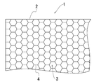
- FIG. 1 is a partial front view (as viewed from the front side) showing a part of the transparent screen 1 according to the embodiment of the present invention.
- a transparent screen 1 is a so-called front projection screen (reflective screen) that mainly displays an image to an observer on the surface side.
- a thin transparent sheet 2 made of plastic On top of this, a thin film 4 is applied as a reflective layer in which a large number of identical hexagonal hole portions 3 are opened in a mesh pattern.
- the transparent screen 1 does not necessarily need to be a front projection screen.
- a so-called rear projection screen transmission screen
- transmission screen transmission screen
- the front projection type screen will be described for convenience of explanation.
- the position of the observer on the “front side” is “back side”, “back side”
- the position of the observer in “” may be read as “front side”.
- the thin film 4 does not necessarily have to be applied only to one side of the transparent sheet 2.
- the thin film 4 may be applied to both sides of the transparent sheet 2.
- the thin film 4 since a thin film is applied on the transparent sheet 2, if the thin film 4 is applied only on one side of the transparent sheet 2, the thin film 4 is formed on both the front and back surfaces of the transparent screen 1. The equivalent reflective layer by is formed.
- the transparent sheet 2 has, for example, a single layer configuration having a resin layer using one kind of highly transparent resin such as acrylic resin, acrylic urethane resin, polyamide resin, or a combination of two or more kinds. Yes.
- the transparent sheet 2 does not necessarily have a single layer configuration.
- the transparent sheet 2 it is preferable to select a material so that the transmission visibility and optical characteristics of the transparent sheet 2 are not impaired.
- Each regular hexagonal hole 3 formed in a mesh shape in the thin film 4 is formed in an equal size.
- the diagonal length (the longest diagonal length) that bisects the regular hexagonal hole 3 is divided into two.
- Sides 5 and 5 of adjacent regular hexagonal hole portions 3 are partitioned by mesh-like line portions 6 having a line width w connected and formed with a uniform width.
- the diagonal line length d and the line width w can be appropriately changed within a predetermined range described later according to the size of the transparent screen 1, the purpose of use, and the like.
- the thin film 4 is formed so that a metallic pigment ink containing a glossy (light reflecting property) metal material such as aluminum and chromium is extremely thin (for example, several to several tens ⁇ m or several ⁇ m or less). It is printed on the transparent sheet 2 by an inkjet method.
- a metallic pigment ink containing a glossy (light reflecting property) metal material such as aluminum and chromium is extremely thin (for example, several to several tens ⁇ m or several ⁇ m or less). It is printed on the transparent sheet 2 by an inkjet method.
- a transparent sheet 2 cut to a size corresponding to the purpose of use is set in an ink jet printer, and a metallic material containing aluminum and chromium is formed so as to form a mesh pattern that forms regular hexagonal holes 3. Pigment ink is applied to the transparent sheet 2.
- the thin film 4 does not necessarily have to be applied with a metallic pigment ink containing aluminum and chromium.
- a metallic pigment ink which mainly contains reflective materials, such as gold
- a metallic pigment ink containing a silver metal material, particularly aluminum and chromium the reflection efficiency is increased and the image displayed on the transparent screen 1 is visually recognized. And the transparent visibility of the background of the transparent screen 1 have the best balance.
- the metallic pigment ink to the transparent sheet 2 using the ink jet method.
- various printing methods such as a screen printing method, a gravure printing method, and an offset printing method can be adopted as appropriate.
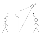
- the image light projected from the projector 7 onto the transparent screen 1 is reflected at a predetermined inclination angle by the mesh-like line portion 6 formed on the thin film 4 as shown in FIG. As shown in FIG. 3, the reflected light reflected by the thin film 4 reaches the eyes of the viewer X on the surface side, and the viewer X can visually recognize a clear image.
- the observer X can visually recognize the background on the back side of the transparent screen 1 through the regular hexagonal hole 3 formed in the thin film 4.
- the transparent sheet 2 uses a highly transparent resin-based material, the background seen through the regular hexagonal hole 3 is almost the same as the background color seen through the transparent screen 1 and the viewer X feels uncomfortable. Will not be given.
- part of the reflected light reflected by the thin film 4 is also reflected to the back side of the transparent screen 1 through the regular hexagonal hole 3. Therefore, the viewer Y on the back side of the transparent screen 1 can also visually recognize the image with a constant sharpness although the visibility is inferior to that on the front side.
- the transmission visibility of the background which the observer Y can see through the transparent screen 1 is not different from that of the observer X.
- the transparent screen 1 was prepared in which the line width w of the mesh-like line portion 6 applied to the transparent sheet 2 was 0.14 mm, and the diagonal length d that bisects the regular hexagonal hole portion 3 was 1.2 mm.
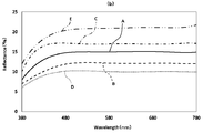
- the results of measuring the visible light transmittance and the visible light reflectance of the transparent screen 1 at this time are shown in FIG.
- the visible light transmittance is the proportion of visible light incident on the transparent screen 1 that is transmitted through the transparent screen 1
- the visible light reflectance is the reflected light of the visible light incident on the transparent screen 1. It is a ratio to do.
- the visible light transmittance of the transparent screen 1 according to Example 1 is about 70% in the wavelength range of 400 to 700 nm, and the visible light reflectance is It was about 15% in the wavelength range of 400 to 700 nm.
- Example 2 As in Example 1, a transparent screen 1 was prepared in which the line width w of the mesh-like line portion 6 was 0.14 mm and the diagonal length d that bisects the regular hexagonal hole portion 3 was 1.6 mm. At this time, as shown in FIGS. 4A and 4B, the visible light transmittance of the transparent screen 1 according to Example 2 (reference B) is about 75% in the wavelength range of 400 to 700 nm. The visible light reflectance was about 12% in the wavelength range of 400 to 700 nm.
- Example 3 As in Example 1 and Example 2, a transparent screen 1 was produced in which the line width w of the mesh-like line part 6 was 0.14 mm and the diagonal length d that bisects the regular hexagonal hole part 3 was 1.0 mm. did. At this time, as shown in FIGS. 4A and 4B, the visible light transmittance of the transparent screen 1 according to Example 3 (reference C) is about 66% in the wavelength range of 400 to 700 nm. The visible light reflectance was about 17% in the wavelength range of 400 to 700 nm.
- a transparent screen 1 was prepared in which the line width w of the mesh-like line portion 6 was 0.14 mm, and the diagonal length d that bisects the regular hexagonal hole portion 3 was 0.8 mm.
- the visible light transmittance of the transparent screen 1 according to Comparative Example 2 (reference E) is approximately 61% in the wavelength range of 400 to 700 nm.
- the visible light reflectance was about 21% in the wavelength range of 400 to 700 nm.
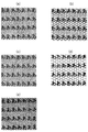
- Table 1 shows the results of projecting video and still image test patterns on the transparent screen 1 created in these examples and comparative examples, and evaluating the optical characteristics of 20 subjects.
- the evaluation was evaluated mainly in terms of transmission visibility and video visibility in three levels: “good”, “normal”, and “bad”.
- “good” in terms of transmission visibility means that the transparency of the transparent screen 1 is high, and “bad” means that the transparent screen 1 is colored in white turbidity or gray and is inferior in transparency. means.
- “good” means that the video displayed on the transparent screen 1 is clear, and “poor” means that the video displayed on the transparent screen 1 is unclear.
- the diagonal length d that bisects the regular hexagonal hole 3 is as long as 2.0 mm, and the area of the regular hexagonal hole 3 occupying the entire transparent screen 1 is relatively large. Visible light transmittance was increased, and the transmission visibility was highly evaluated. On the other hand, since the total area of the mesh-like line portion 6 on the transparent screen 1 is relatively small and the reflectance is low, the image displayed on the transparent screen 1 is unclear and the image visibility is low. .
- the diagonal length d that bisects the regular hexagonal hole 3 is as short as 0.8 mm, and the mesh-like line portion 6 occupying the entire transparent screen 1 is as follows. Since the total area is relatively large, the reflectance of visible light is increased, and the visibility of the image is highly evaluated. On the other hand, since the total area of the regular hexagonal hole 3 in the transparent screen 1 is relatively small and the transmittance is low, the transparent screen 1 is given an impression that it is colored in gray as a whole. It became low evaluation.
- FIG. 5 is an actual test pattern video (still image) confirmed by the subject.
- the diagonal d is changed (that is, the ratio of the line width w to the diagonal d is changed)
- the transmittance and the reflectance are changed, whereby the transmission visibility and the image visibility in the entire transparent screen 1 are also changed.
- the influence of the line width w of the mesh-like line portion 6 and the diagonal length d that bisects the regular hexagonal hole portion 3 on the visible light transmittance and the visible light reflectance of the transparent screen 1 is as follows.
- the relationship is as follows.
- the transparent screen 1 according to the first to third embodiments has a good balance between transmission visibility and video visibility.
- the transparent screen 1 according to the first embodiment has transmission transparency and video visibility. Is the most balanced.
- the thin film 4 has an average visible light transmittance of 66 to 75%, preferably 70%, and an average visible light reflectance of 10 to 17%, preferably 15%.
- the transparent screen 1 in which the transparency visibility and the image visibility are most balanced is obtained.
- the ratio (w / d) between the line width w and the diagonal length d at that time is 7/80 to 7/50.
- the transparent screen to which the present invention is applied and the method for manufacturing the transparent screen can project and display an image clearly without impairing transmission visibility.
Landscapes
- Physics & Mathematics (AREA)
- General Physics & Mathematics (AREA)
- Optics & Photonics (AREA)
- Chemical & Material Sciences (AREA)
- Engineering & Computer Science (AREA)
- Theoretical Computer Science (AREA)
- Mechanical Engineering (AREA)
- Dispersion Chemistry (AREA)
- General Chemical & Material Sciences (AREA)
- Chemical Kinetics & Catalysis (AREA)
- Materials Engineering (AREA)
- Metallurgy (AREA)
- Organic Chemistry (AREA)
- Overhead Projectors And Projection Screens (AREA)
- Optical Elements Other Than Lenses (AREA)
Abstract
Description
先ず、透明シート2に塗布された網目状線部6の線幅wを0.14mm、正六角形孔部3を2分する対角線長さdを1.2mmとした透明スクリーン1を作製した。この時の透明スクリーン1の可視光線透過率と可視光線反射率を計測した結果を図4に示す。ここで、可視光線透過率とは、透明スクリーン1に入射する可視光線のうち透明スクリーン1を透過する割合、可視光線反射率とは、透明スクリーン1に入射する可視光線のうち透明スクリーン1を反射する割合である。
実施例1と同じく、網目状線部6の線幅wを0.14mmとし、正六角形孔部3を2分する対角線長さdを1.6mmとした透明スクリーン1を作製した。
この時、図4(a)、及び図4(b)に示す通り、実施例2(符号B)に係る透明スクリーン1の可視光線透過率は、波長400~700nmの範囲で約75%であり、可視光線反射率は波長400~700nmの範囲で約12%であった。
実施例1、及び実施例2と同じく、網目状線部6の線幅wを0.14mmとし、正六角形孔部3を2分する対角線長さdを1.0mmとした透明スクリーン1を作製した。この時、図4(a)、及び図4(b)に示す通り、実施例3(符号C)に係る透明スクリーン1の可視光線透過率は、波長400~700nmの範囲で約66%であり、可視光線反射率は波長400~700nmの範囲で約17%であった。
網目状線部6の線幅wを0.14mmとし、正六角形孔部3を2分する対角線長さdを2.0mmとした透明スクリーン1を作製した。この時、図4(a)、及び図4(b)に示す通り、比較例1(符号D)に係る透明スクリーン1の可視光線透過率は、波長400~700nmの範囲で約80%であり、可視光線反射率は波長400~700nmの範囲で約10%であった。
網目状線部6の線幅wを0.14mmとし、正六角形孔部3を2分する対角線長さdを0.8mmとした透明スクリーン1を作製した。この時、図4(a)、及び図4(b)に示す通り、比較例2(符号E)に係る透明スクリーン1の可視光線透過率は、波長400~700nmの範囲で約61%であり、可視光線反射率は波長400~700nmの範囲で約21%であった。

◎「良い」と感じた被験者が半数以上で、「悪い」と感じた被験者無し
○「良い」と感じた被験者が半数未満で、「悪い」と感じた被験者無し
△「良い」若しくは「普通」と感じた被験者の総数が、「悪い」と感じた被験者の総数よりも多い
×「悪い」と感じた被験者が半数以上で、「良い」と感じた被験者無し
2 透明シート
3 正六角形孔部
4 薄膜
5 正六角形孔部の辺
6 網目状線部
7、104 プロジェクタ
X、Y 観察者
101 スクリーン板
102 表示装置
103 フロントガラス
201 黒色フィルム
202 アルミニウム膜
203 光拡散層
204 貫通孔
Claims (5)
- 透明シートと、
該透明シート上に配置され、多数の均等な大きさの正六角形孔部が網目状に形成され、隣り合う前記正六角形孔部の一方の辺部と他方の辺部が互いに均等幅で接続形成された網目状線部の線幅をw、前記正六角形孔部を2分する対角線長さをdとしたときに、wとdの比(w/d)が7/80~7/50の範囲である金属素材の薄膜と、を備える
透明スクリーン。 - 少なくとも波長400~700nmの領域における可視光線の平均透過率が略66~75%であり、少なくとも波長400~700nmの領域における可視光線の平均反射率が略12~17%である
請求項1に記載の透明スクリーン。 - 前記薄膜は、少なくともアルミニウム、及びクロムを含有するメタリック顔料インクで製造された
請求項1又は請求項2に記載の透明スクリーン。 - 透明シートを所定の形状に加工する工程と、
前記透明シート上に、隣り合う正六角形孔部の一方の辺部と他方の辺部が互いに均等幅で接続形成された網目状線部の線幅をw、前記正六角形孔部を2分する対角線長さをdとしたときに、wとdの比(w/d)が7/80~7/50の範囲となる多数の均等な大きさの前記正六角形孔部が網目状に形成された金属素材の薄膜を配置する工程と、を備える
透明スクリーンの製造方法。 - 前記薄膜を配置する工程は、
前記薄膜を前記透明シート上に、少なくともアルミニウム、及びクロムを含有するメタリック顔料インクを用いて所定の印刷方式により印刷する
請求項4に記載の透明スクリーンの製造方法。
Priority Applications (3)
| Application Number | Priority Date | Filing Date | Title |
|---|---|---|---|
| EP15875399.6A EP3242162B1 (en) | 2014-12-29 | 2015-12-24 | Transparent screen and method for manufacturing transparent screen |
| US15/531,711 US10042242B2 (en) | 2014-12-29 | 2015-12-24 | Transparent screen and method for manufacturing transparent screen |
| JP2016567305A JP6115981B2 (ja) | 2014-12-29 | 2015-12-24 | 透明スクリーン、及び透明スクリーンの製造方法 |
Applications Claiming Priority (2)
| Application Number | Priority Date | Filing Date | Title |
|---|---|---|---|
| JP2014267054 | 2014-12-29 | ||
| JP2014-267054 | 2014-12-29 |
Publications (1)
| Publication Number | Publication Date |
|---|---|
| WO2016108273A1 true WO2016108273A1 (ja) | 2016-07-07 |
Family
ID=56284427
Family Applications (1)
| Application Number | Title | Priority Date | Filing Date |
|---|---|---|---|
| PCT/JP2015/086009 Ceased WO2016108273A1 (ja) | 2014-12-29 | 2015-12-24 | 透明スクリーン、及び透明スクリーンの製造方法 |
Country Status (4)
| Country | Link |
|---|---|
| US (1) | US10042242B2 (ja) |
| EP (1) | EP3242162B1 (ja) |
| JP (1) | JP6115981B2 (ja) |
| WO (1) | WO2016108273A1 (ja) |
Cited By (3)
| Publication number | Priority date | Publication date | Assignee | Title |
|---|---|---|---|---|
| WO2019150996A1 (ja) * | 2018-01-30 | 2019-08-08 | パナソニックIpマネジメント株式会社 | 言語提示装置、言語提示方法、及び言語提示プログラム |
| KR102103650B1 (ko) * | 2018-11-23 | 2020-04-23 | 정승혁 | 반투과형 메쉬타입 반사스크린 제조방법 |
| KR20230069476A (ko) * | 2021-11-12 | 2023-05-19 | 김종찬 | 암막 전동커튼과 투과도 가변유리 기능을 활용한 투명유리 야외극장 |
Families Citing this family (4)
| Publication number | Priority date | Publication date | Assignee | Title |
|---|---|---|---|---|
| WO2019146423A1 (ja) * | 2018-01-25 | 2019-08-01 | 富士フイルム株式会社 | 投映像表示用部材、ウインドシールドガラスおよびヘッドアップディスプレイシステム |
| CN108303847B (zh) * | 2018-04-13 | 2025-03-04 | 无锡视美乐激光显示科技有限公司 | 透光幕、投影幕及投影显示系统 |
| WO2025180002A1 (zh) * | 2024-02-28 | 2025-09-04 | 青岛海信激光显示股份有限公司 | 抬头显示装置 |
| DE102024123002B3 (de) * | 2024-08-12 | 2025-07-03 | Webasto SE | Bildanzeigesystem für ein Kraftfahrzeug und Kraftfahrzeug mit derartigem Bildanzeigesystem |
Citations (7)
| Publication number | Priority date | Publication date | Assignee | Title |
|---|---|---|---|---|
| JPS63172259A (ja) * | 1987-01-12 | 1988-07-15 | Seiko Epson Corp | 両面視認型投写表示装置 |
| JP2000305179A (ja) * | 1999-04-19 | 2000-11-02 | Toshiba Corp | 投射型スクリーン |
| JP2006106135A (ja) * | 2004-09-30 | 2006-04-20 | Uejima Yutaka | 映像投影装置 |
| JP2006119489A (ja) * | 2004-10-25 | 2006-05-11 | Kimoto & Co Ltd | 反射型スクリーン |
| JP2008076783A (ja) * | 2006-09-22 | 2008-04-03 | Dainippon Printing Co Ltd | レンズアレイシート、面光源装置、背面投射型表示装置、レンズアレイシートの製造方法 |
| US20130330486A1 (en) * | 2012-06-07 | 2013-12-12 | Mind Flow Llc | One-Way Graphics Materials and Methods |
| JP2014013369A (ja) * | 2012-06-06 | 2014-01-23 | Dainippon Printing Co Ltd | スクリーン、及びスクリーンの製造方法 |
Family Cites Families (12)
| Publication number | Priority date | Publication date | Assignee | Title |
|---|---|---|---|---|
| JPS60168103A (ja) * | 1984-02-13 | 1985-08-31 | Nissan Motor Co Ltd | 透光板 |
| JPH01157333U (ja) * | 1988-04-21 | 1989-10-30 | ||
| US5361163A (en) * | 1991-06-03 | 1994-11-01 | Dai Nippon Printing Co., Ltd. | Reflection type projection screen, production process thereof, and production apparatus thereof |
| US6695453B2 (en) * | 2001-02-09 | 2004-02-24 | Avery Dennison Corporation | Rear projection screens and light filters with conformable coatings and methods of making the same |
| JP4378093B2 (ja) * | 2002-06-06 | 2009-12-02 | 株式会社ユポ・コーポレーション | スクリーン |
| EP1583995B1 (en) * | 2002-12-18 | 2010-11-03 | Vizoo Invest Aps | A method and an arrangement for projecting images and projection screen arrangement |
| JP4680488B2 (ja) * | 2003-07-18 | 2011-05-11 | 株式会社きもと | 広告シート、広告シートの作製材料 |
| JP2008012916A (ja) * | 2006-06-08 | 2008-01-24 | Hitachi Via Mechanics Ltd | 複合シート、複合シートの加工方法、及びレーザ加工装置 |
| JP2011117161A (ja) * | 2009-12-02 | 2011-06-16 | Toppan Printing Co Ltd | 遮光性窓用フィルム |
| JP2011122395A (ja) * | 2009-12-14 | 2011-06-23 | Toppan Printing Co Ltd | 電子情報可変表示機能付き遮光性窓用フィルム |
| FR2986624B1 (fr) * | 2012-02-03 | 2015-02-27 | Thales Sa | Projecteur optique a ecran de projection semi-transparent |
| JP2014206706A (ja) | 2013-04-16 | 2014-10-30 | パイオニア株式会社 | 表示装置、表示方法、及び表示プログラム |
-
2015
- 2015-12-24 JP JP2016567305A patent/JP6115981B2/ja not_active Expired - Fee Related
- 2015-12-24 US US15/531,711 patent/US10042242B2/en active Active
- 2015-12-24 WO PCT/JP2015/086009 patent/WO2016108273A1/ja not_active Ceased
- 2015-12-24 EP EP15875399.6A patent/EP3242162B1/en active Active
Patent Citations (7)
| Publication number | Priority date | Publication date | Assignee | Title |
|---|---|---|---|---|
| JPS63172259A (ja) * | 1987-01-12 | 1988-07-15 | Seiko Epson Corp | 両面視認型投写表示装置 |
| JP2000305179A (ja) * | 1999-04-19 | 2000-11-02 | Toshiba Corp | 投射型スクリーン |
| JP2006106135A (ja) * | 2004-09-30 | 2006-04-20 | Uejima Yutaka | 映像投影装置 |
| JP2006119489A (ja) * | 2004-10-25 | 2006-05-11 | Kimoto & Co Ltd | 反射型スクリーン |
| JP2008076783A (ja) * | 2006-09-22 | 2008-04-03 | Dainippon Printing Co Ltd | レンズアレイシート、面光源装置、背面投射型表示装置、レンズアレイシートの製造方法 |
| JP2014013369A (ja) * | 2012-06-06 | 2014-01-23 | Dainippon Printing Co Ltd | スクリーン、及びスクリーンの製造方法 |
| US20130330486A1 (en) * | 2012-06-07 | 2013-12-12 | Mind Flow Llc | One-Way Graphics Materials and Methods |
Non-Patent Citations (1)
| Title |
|---|
| See also references of EP3242162A4 * |
Cited By (4)
| Publication number | Priority date | Publication date | Assignee | Title |
|---|---|---|---|---|
| WO2019150996A1 (ja) * | 2018-01-30 | 2019-08-08 | パナソニックIpマネジメント株式会社 | 言語提示装置、言語提示方法、及び言語提示プログラム |
| KR102103650B1 (ko) * | 2018-11-23 | 2020-04-23 | 정승혁 | 반투과형 메쉬타입 반사스크린 제조방법 |
| KR20230069476A (ko) * | 2021-11-12 | 2023-05-19 | 김종찬 | 암막 전동커튼과 투과도 가변유리 기능을 활용한 투명유리 야외극장 |
| KR102539984B1 (ko) * | 2021-11-12 | 2023-06-05 | 김종찬 | 암막 전동커튼과 투과도 가변유리 기능을 활용한 투명유리 야외극장 |
Also Published As
| Publication number | Publication date |
|---|---|
| EP3242162A1 (en) | 2017-11-08 |
| US20170336704A1 (en) | 2017-11-23 |
| US10042242B2 (en) | 2018-08-07 |
| JPWO2016108273A1 (ja) | 2017-04-27 |
| EP3242162A4 (en) | 2018-08-29 |
| JP6115981B2 (ja) | 2017-04-19 |
| EP3242162B1 (en) | 2021-05-05 |
Similar Documents
| Publication | Publication Date | Title |
|---|---|---|
| JP6115981B2 (ja) | 透明スクリーン、及び透明スクリーンの製造方法 | |
| JP3455854B2 (ja) | 光透過像を有するパネル | |
| US11011135B2 (en) | Head-up display with transparency mask | |
| JP2826367B2 (ja) | 背後照明ディスプレー | |
| CN115503364B (zh) | 一种用于显示屏的显示盖板及其制备方法、显示屏 | |
| CN114600182A (zh) | 显示装置 | |
| DE102010031192A1 (de) | Lentikular-Leuchtvorrichtung | |
| JP5339120B2 (ja) | 表示装置 | |
| JP3970250B2 (ja) | 立体表現印刷物および立体表現印刷法 | |
| JP7180278B2 (ja) | 加飾フィルムおよび表示装置 | |
| JP2022044351A (ja) | 加飾シート、加飾シート付き表示装置、加飾シートの製造方法、及び、加飾シート付き表示装置の製造方法 | |
| JP5545948B2 (ja) | 計器板のヘアライン表示構造 | |
| HK1241472B (en) | Transparent screen and method for manufacturing transparent screen | |
| JP7153223B2 (ja) | パララックスバリア及びバリア付き表示装置 | |
| JP2004317801A (ja) | 面状立体視認化装置 | |
| HK1241472A1 (en) | Transparent screen and method for manufacturing transparent screen | |
| JP2019086378A (ja) | 車両用表示装置及び意匠板 | |
| JP2022028602A (ja) | パネル装置 | |
| JP2009058795A (ja) | 画像表示シート及び画像表示製品 | |
| JP5713382B2 (ja) | メタリックカード | |
| KR100666003B1 (ko) | 자동차 계기용 문자판의 인쇄방법 | |
| JP2021012287A (ja) | 表示装置 | |
| JP2020041855A (ja) | 樹脂装飾部品及び文字板 | |
| JP2006072212A (ja) | 画像シート及びレンズ状シート | |
| JP2023162933A (ja) | 加飾薄状物、及び該加飾薄状物を備えた表示装置 |
Legal Events
| Date | Code | Title | Description |
|---|---|---|---|
| 121 | Ep: the epo has been informed by wipo that ep was designated in this application |
Ref document number: 15875399 Country of ref document: EP Kind code of ref document: A1 |
|
| ENP | Entry into the national phase |
Ref document number: 2016567305 Country of ref document: JP Kind code of ref document: A |
|
| WWE | Wipo information: entry into national phase |
Ref document number: 15531711 Country of ref document: US |
|
| REEP | Request for entry into the european phase |
Ref document number: 2015875399 Country of ref document: EP |
|
| NENP | Non-entry into the national phase |
Ref country code: DE |