WO2016111005A1 - スピーカ装置 - Google Patents
スピーカ装置 Download PDFInfo
- Publication number
- WO2016111005A1 WO2016111005A1 PCT/JP2015/050504 JP2015050504W WO2016111005A1 WO 2016111005 A1 WO2016111005 A1 WO 2016111005A1 JP 2015050504 W JP2015050504 W JP 2015050504W WO 2016111005 A1 WO2016111005 A1 WO 2016111005A1
- Authority
- WO
- WIPO (PCT)
- Prior art keywords
- curved plate
- diaphragm
- speaker device
- arc
- curvature
- Prior art date
- Legal status (The legal status is an assumption and is not a legal conclusion. Google has not performed a legal analysis and makes no representation as to the accuracy of the status listed.)
- Ceased
Links
Images


Classifications
-
- H—ELECTRICITY
- H04—ELECTRIC COMMUNICATION TECHNIQUE
- H04R—LOUDSPEAKERS, MICROPHONES, GRAMOPHONE PICK-UPS OR LIKE ACOUSTIC ELECTROMECHANICAL TRANSDUCERS; ELECTRIC HEARING AIDS; PUBLIC ADDRESS SYSTEMS
- H04R1/00—Details of transducers, loudspeakers or microphones
- H04R1/02—Casings; Cabinets ; Supports therefor; Mountings therein
- H04R1/025—Arrangements for fixing loudspeaker transducers, e.g. in a box, furniture
-
- B—PERFORMING OPERATIONS; TRANSPORTING
- B60—VEHICLES IN GENERAL
- B60Q—ARRANGEMENT OF SIGNALLING OR LIGHTING DEVICES, THE MOUNTING OR SUPPORTING THEREOF OR CIRCUITS THEREFOR, FOR VEHICLES IN GENERAL
- B60Q5/00—Arrangement or adaptation of acoustic signal devices
- B60Q5/005—Arrangement or adaptation of acoustic signal devices automatically actuated
- B60Q5/008—Arrangement or adaptation of acoustic signal devices automatically actuated for signaling silent vehicles, e.g. for warning that a hybrid or electric vehicle is approaching
-
- G—PHYSICS
- G10—MUSICAL INSTRUMENTS; ACOUSTICS
- G10K—SOUND-PRODUCING DEVICES; METHODS OR DEVICES FOR PROTECTING AGAINST, OR FOR DAMPING, NOISE OR OTHER ACOUSTIC WAVES IN GENERAL; ACOUSTICS NOT OTHERWISE PROVIDED FOR
- G10K13/00—Cones, diaphragms, or the like, for emitting or receiving sound in general
-
- H—ELECTRICITY
- H04—ELECTRIC COMMUNICATION TECHNIQUE
- H04R—LOUDSPEAKERS, MICROPHONES, GRAMOPHONE PICK-UPS OR LIKE ACOUSTIC ELECTROMECHANICAL TRANSDUCERS; ELECTRIC HEARING AIDS; PUBLIC ADDRESS SYSTEMS
- H04R7/00—Diaphragms for electromechanical transducers; Cones
- H04R7/02—Diaphragms for electromechanical transducers; Cones characterised by the construction
- H04R7/12—Non-planar diaphragms or cones
- H04R7/127—Non-planar diaphragms or cones dome-shaped
-
- H—ELECTRICITY
- H04—ELECTRIC COMMUNICATION TECHNIQUE
- H04R—LOUDSPEAKERS, MICROPHONES, GRAMOPHONE PICK-UPS OR LIKE ACOUSTIC ELECTROMECHANICAL TRANSDUCERS; ELECTRIC HEARING AIDS; PUBLIC ADDRESS SYSTEMS
- H04R7/00—Diaphragms for electromechanical transducers; Cones
- H04R7/16—Mounting or tensioning of diaphragms or cones
- H04R7/18—Mounting or tensioning of diaphragms or cones at the periphery
-
- H—ELECTRICITY
- H04—ELECTRIC COMMUNICATION TECHNIQUE
- H04R—LOUDSPEAKERS, MICROPHONES, GRAMOPHONE PICK-UPS OR LIKE ACOUSTIC ELECTROMECHANICAL TRANSDUCERS; ELECTRIC HEARING AIDS; PUBLIC ADDRESS SYSTEMS
- H04R9/00—Transducers of moving-coil, moving-strip, or moving-wire type
- H04R9/02—Details
- H04R9/025—Magnetic circuit
-
- H—ELECTRICITY
- H04—ELECTRIC COMMUNICATION TECHNIQUE
- H04R—LOUDSPEAKERS, MICROPHONES, GRAMOPHONE PICK-UPS OR LIKE ACOUSTIC ELECTROMECHANICAL TRANSDUCERS; ELECTRIC HEARING AIDS; PUBLIC ADDRESS SYSTEMS
- H04R9/00—Transducers of moving-coil, moving-strip, or moving-wire type
- H04R9/06—Loudspeakers
-
- H—ELECTRICITY
- H04—ELECTRIC COMMUNICATION TECHNIQUE
- H04R—LOUDSPEAKERS, MICROPHONES, GRAMOPHONE PICK-UPS OR LIKE ACOUSTIC ELECTROMECHANICAL TRANSDUCERS; ELECTRIC HEARING AIDS; PUBLIC ADDRESS SYSTEMS
- H04R2400/00—Loudspeakers
- H04R2400/11—Aspects regarding the frame of loudspeaker transducers
-
- H—ELECTRICITY
- H04—ELECTRIC COMMUNICATION TECHNIQUE
- H04R—LOUDSPEAKERS, MICROPHONES, GRAMOPHONE PICK-UPS OR LIKE ACOUSTIC ELECTROMECHANICAL TRANSDUCERS; ELECTRIC HEARING AIDS; PUBLIC ADDRESS SYSTEMS
- H04R2499/00—Aspects covered by H04R or H04S not otherwise provided for in their subgroups
- H04R2499/10—General applications
- H04R2499/13—Acoustic transducers and sound field adaptation in vehicles
Definitions
- the present invention relates to a speaker device.
- Hybrid vehicles and electric vehicles are highly silent when traveling, and even if such vehicles approach a pedestrian or other passerby, the passerby may not notice the approach. Therefore, various speaker devices mounted on hybrid vehicles and the like have been proposed in order to generate a notification sound that informs a passerby of the approach of a hybrid vehicle or the like (see, for example, Patent Document 1).
- the specifications of such a speaker device are uniquely determined by each manufacturer. For example, the speaker device has not been designed based on a standard standard for heat resistance and environmental resistance.
- the invention described in claim 1 includes a diaphragm made of a film containing polyimide, and a frame that supports the diaphragm, and passes through the center of the diaphragm to emit sound.
- the cross section parallel to the sound radiation direction is, in order from the inner periphery to the outer periphery of the diaphragm, in order from the inner periphery to the outer periphery, a first curved plate having a concave arc, a second curved plate having a convex arc, A third curved plate having a circular arc and a fourth curved plate having a convex circular arc, and the area of the first curved plate is the second curved plate, the third curved plate, and the fourth curved plate. It is a speaker device characterized by being larger than any of the respective areas.
- FIG. 4 is a perspective view showing the speaker device shown in FIG. 1 cut so that the cross section shown in FIG. 3 can be seen.
- FIG. 4 is a partial cross-sectional view showing the cross section of the diaphragm shown in FIG. 3 with respect to the right half in the drawing.
- FIG. 6 is a diagram schematically showing a cross section of the diaphragm shown in FIG. 5. It is a graph which shows the frequency characteristic of the reproduction sound pressure in the speaker apparatus shown by FIG. 1, and an impedance. It is a figure which shows the shape of the cross section along the sound radiation direction of the diaphragm concerning 2nd Example of this invention.
- a speaker device includes a diaphragm made of a film containing polyimide, and a frame that supports the diaphragm, and a cross-section passing through the center of the diaphragm and parallel to the sound radiation direction is A first curved plate having a concave arc, a second curved plate having a convex arc, and a third song having a concave arc in order from the inner peripheral portion to the outer peripheral portion of the diaphragm with respect to the sound radiation direction. And a fourth curved plate having a convex arc, wherein the first curved plate has an area of each of the second curved plate, the third curved plate, and the fourth curved plate. It is characterized by being larger than either.
- a speaker device mounted on a vehicle to generate a notification sound that informs a passerby that a vehicle is approaching is assumed to have a situation where a high-pressure water flow is struck against the diaphragm from outside the vehicle.
- Water resistance in terms of strength that can withstand pressure is also required.
- heat resistance and water resistance are improved by forming the diaphragm with a film containing polyimide.
- each curved plate including the first curved plate that has the largest area in plan view and receives the pressure of the water flow most includes a circular arc in a cross section passing through the center of the diaphragm and parallel to the sound radiation direction. Such an arc has a mechanically uniform structure in any part.
- the force inside the diaphragm generated by the pressure of the water around the diaphragm acts evenly on each part of the diaphragm, and as a result, the force can be dispersed, so that it can withstand such water flow pressure.
- a part of the first curved plate, the second curved plate, the third curved plate, and the fourth curved plate is not easily deformed by the predetermined pressure of the water flow, and even if it is temporarily deformed, it returns to the predetermined shape. What can be done is an example.
- the shape of the cross section of the first curved plate that mainly plays the role of sound radiation in the diaphragm has an arc whose cross section parallel to the sound radiation direction is concave with respect to the sound radiation direction. It is difficult for high frequency vibration to be transmitted to the first curved plate, and high frequency sound is difficult to be produced. However, what is often required as the notification sound is mainly low-frequency sound. Moreover, in this embodiment, it is excellent in the water resistance in an intensity
- the second curved plate, the third curved plate, and the fourth curved plate which are located on the outer peripheral side of the first curved plate and have a part also serving as an edge, have a circular arc shape as described above. It has excellent water resistance in terms of strength.
- the radius of curvature of the arc of the first curved plate is larger than the radius of curvature of the arc of the third curved plate, and the radius of curvature of the circular arc of the fourth curved plate. Is smaller than the radius of curvature of the arc of the second curved plate. That is, in this speaker device, the radius of curvature of the arc of the first curved plate that plays the role of sound radiation is larger than the radius of curvature of the arc of the third curved plate that also plays the role of edge. Further, the radius of curvature of the arc of the second curved plate is smaller than the radius of curvature of the arc of the third curved plate.
- the radius of curvature of the arc of the second curved plate located near the inner periphery of the edge close to the first curved plate is the curvature of the arc of the third curved plate located near the center in the width direction of the edge. It is smaller than the radius.
- the reverse resonance frequency can be set to 5 kHz or more, for example, and a large dip can be prevented from appearing in the frequency band of 5 kHz or less.
- the diaphragm includes the second curved plate having a convex arc cross section, the third curved plate having a concave arc cross section, and a convex shape.
- a fourth curved plate having a cross section of the arc.
- the cross-sectional shapes that pass through the centers of the diaphragms of the second curved plate, the third curved plate, and the fourth curved plate and are parallel to the sound radiation direction are all arcs.
- Such an arc has a mechanically uniform structure in any part.
- the force inside the diaphragm generated by the pressure of water around the diaphragm acts evenly on each part of the diaphragm, and as a result, the force can be dispersed. That is, according to said speaker apparatus, the water resistance in the intensity
- an opening is provided in a central portion of the first curved plate, the opening is covered with a cap, and the cap is the center of the diaphragm.
- the cross section passing through and parallel to the sound emission direction is a concave arc with respect to the sound emission direction.
- Such an arc has a mechanically uniform structure in any part. Therefore, the force inside the cap generated by the pressure of water around the cap acts equally on each part of the cap, and as a result, the force can be distributed. That is, according to said speaker apparatus, the water resistance in the intensity
- an example is that a part of the cap is not easily deformed by a predetermined pressure of the water flow and can be restored to a predetermined shape even if it is temporarily deformed.
- the cap is made of a film containing polyimide. Thereby, the heat resistance and water resistance of the cap can be further improved.
- the radius of curvature of the arc of the cap is smaller than the radius of curvature of the arc of the first curved plate. Smaller radius caps have higher mechanical strength.
- the diaphragm has a thickness of 50 ⁇ m, 75 ⁇ m, 100 ⁇ m, or 125 ⁇ m.
- the general-purpose polyimide film has a film thickness of 50 ⁇ m, 75 ⁇ m, 100 ⁇ m, 125 ⁇ m, or the like.
- the diaphragm has a thickness of 125 ⁇ m.
- the diaphragm is arranged in the vehicle and generates a notification sound that informs the vehicle toward the outside of the vehicle.
- a speaker device for notification sound requires high reproduction sound pressure and high heat resistance and water resistance.
- This speaker device has the above-described high reproduction sound pressure and high heat resistance and water resistance.
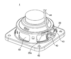
- FIG. 1 is a perspective view of a speaker device according to a first embodiment of the present invention as viewed from a sound emission destination.
- FIG. 2 is a perspective view of the speaker device shown in FIG. 1 as viewed from the back side with respect to the sound radiation destination.
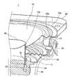
- FIG. 3 is a cross-sectional view showing a cross section of the speaker device shown in FIG. 1 along the sound emission direction.
- 4 is a perspective view of the speaker device shown in FIG. 1 cut so that the cross section shown in FIG. 3 can be seen.
- the speaker device 1 is mounted on a vehicle having high quietness during traveling, such as a hybrid vehicle or an electric vehicle, and emits a notification sound that informs a passerby that the vehicle is approaching.
- the speaker device 1 has a diaphragm 10, a frame 20, a damper 30, a voice coil 40, a magnetic circuit 50, and a cap 60.
- the diaphragm 10 is a diaphragm whose outer peripheral shape is circular, and an opening 10a is formed at the center thereof.
- the vicinity of the outer peripheral edge 10 b of the diaphragm 10 is connected and supported by the cylindrical frame 20, and the vicinity of the inner peripheral edge of the opening 10 a in the diaphragm 10 is connected and supported by the peripheral surface near the upper edge of the cylindrical voice coil bobbin 41.
- the upper edge of the voice coil bobbin 41 slightly protrudes in the sound emission direction from the opening 10 a, and the opening 10 a is covered with a cap 60 that covers the upper edge of the voice coil bobbin 41.
- the damper 30 is an annular member having flexibility, the outer peripheral edge is connected and supported by the frame 20, and the inner peripheral edge is connected and supported by the peripheral surface of the voice coil bobbin 41.
- the voice coil 40 is formed on the peripheral surface of the voice coil bobbin 41 and is disposed in the magnetic gap 51 in the magnetic circuit 50.
- the voice coil 40 is connected to an external wiring 44 through an internal wiring 42 and a wiring terminal 43.
- the wiring terminal 43 is fixed to the outer surface of the frame 20.
- One end of the internal wiring 42 is connected to the voice coil 40 and is routed inside the frame 20, and the other end is connected to the wiring terminal 43 through the opening 20 a of the frame 20.
- One end of the external wiring 44 is connected to the wiring terminal 43.
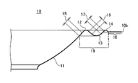
- FIG. 5 is a partial cross-sectional view showing the cross section of the diaphragm shown in FIG. 3 with respect to the right half in the figure
- FIG. 6 schematically shows the cross section of the diaphragm shown in FIG. FIG.
- the diaphragm 10 has a first curved plate 11, a second curved plate 12, a third curved plate 13, and a fourth curved plate 14.
- the first curved plate 11 is located at the center of the diaphragm 10, and the cross section parallel to the sound radiation direction has a concave arc with respect to the sound radiation direction.
- the first curved plate 11 has a ring shape with an opening 10a at the center when viewed from the sound radiation direction.
- the circular arc shape in the cross section of the first curved plate 11 has a bowl shape as a whole by connecting the circular arc shown only in the right half in FIG. 5 to the left half not shown.
- the arc shape of the cross section of the first curved plate according to the present invention is not limited to such a bowl-shaped arc shape.
- the arc shape of the cross section of the first curved plate referred to in the present invention is such that, for example, the cross section consists of two arcs as a whole if the cross section of one side portion from the center of the first curved plate to the outer periphery is an arc shape. It may be W-shaped.
- the second curved plate 12 is located on the outer peripheral side of the first curved plate 11, and a cross section parallel to the sound radiation direction has a convex arc with respect to the sound radiation direction.
- the second curved plate 12 has a ring shape when viewed from the sound emission direction.
- the 3rd curved plate 13 is located in the outer peripheral side of the 2nd curved plate 12, and the cross section parallel to a sound radiation direction has a concave arc with respect to this sound radiation direction.
- the third curved plate 13 has a ring shape when viewed from the sound radiation direction.
- the fourth curved plate 14 is located between the outer peripheral side of the third curved plate 13 and the outer peripheral edge 10b of the diaphragm 10, and the cross section parallel to the sound radiation direction has a convex arc with respect to the sound radiation direction.
- the fourth curved plate 14 has a ring shape when viewed from the sound radiation direction.
- the first curved plate 11 has a larger planar view area when viewed from the sound radiation direction than any of the second curved plate 12, the third curved plate 13, and the fourth curved plate 14.
- the first curved plate 11 mainly plays a role of sound radiation, is located on the outer peripheral side of the first curved plate 11, the second curved plate 12, the third curved plate 13, and the fourth curved plate 14.
- the portion 19 having a main role of the edge.
- the outer peripheral edge of the first curved plate 11 and the inner peripheral edge of the second curved plate 12 are connected by a first inclined portion 15 whose cross section parallel to the sound radiation direction is a straight line.
- the outer periphery of the 2nd curved plate 12 and the inner periphery of the 3rd curved plate 13 are connected by the 2nd inclination part 16 whose cross section parallel to a sound radiation direction is a straight line.
- the outer periphery of the 3rd curved plate 13 and the inner periphery of the 4th curved plate 14 are connected by the 3rd inclination part 17 whose cross section parallel to a sound radiation direction is a straight line.
- a flat ring portion 18 that is a straight line substantially orthogonal to the sound radiation direction.
- the flat ring portion 18 is affixed to the upper surface of the frame 20 so that the diaphragm 10 is connected and supported by the frame 20 in the vicinity of the outer peripheral edge 10b.
- the flat ring portion 18 is an allowance for the frame 20.
- the speaker device 1 of this embodiment that is mounted on the vehicle so as to emit a notification sound that informs the passerby of the approach of the vehicle, it is assumed that a high-pressure water flow strikes the diaphragm from the outside of the vehicle. Water resistance is also required in terms of strength that can withstand such water flow pressure. According to the speaker device 1 of the present embodiment, the heat resistance and water resistance are improved by forming the diaphragm 10 with a film containing polyimide. Further, each of the curved plates 11 to 14 including the first curved plate 11 that has the largest area in plan view and receives the pressure of the water flow most has an arc in a cross section parallel to the sound radiation direction. Such an arc has a mechanically uniform structure in any part.
- the force inside the diaphragm generated by the pressure of water around the diaphragm acts evenly on each part of the diaphragm, and as a result, the force can be dispersed.
- this improves the water resistance in terms of strength that can withstand the pressure of the water flow as described above.
- an example is that a part of the cap is not easily deformed by a predetermined pressure of the water flow and can be restored to a predetermined shape even if it is temporarily deformed.
- the shape of the cross section of the first curved plate 11 that mainly plays the role of sound radiation in the diaphragm 10 has an arc whose cross section parallel to the sound radiation direction is concave with respect to the sound radiation direction.
- the high frequency vibration of the coil is difficult to be transmitted to the first curved plate 11, and high frequency sound is difficult to be produced.
- what is often required as the above notification sound is mainly low frequency sound of, for example, 5 KHz or less, and in this embodiment, the above-described shape of the first curved plate 11 provides water resistance in terms of strength. Excellent in properties.
- the cross section of the 2nd curved plate 12, the 3rd curved plate 13, and the 4th curved plate 14 which the part 19 which is located in the outer peripheral side of the 1st curved plate 11 and also plays a role of the edge is the above-mentioned. It is excellent in water resistance in terms of strength because it has such an arc.
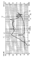
- FIG. 7 is a graph showing the frequency characteristics of reproduced sound pressure and impedance in the speaker device shown in FIG.
- the horizontal axis represents frequency [Hz]
- the left vertical axis in the figure represents reproduction sound pressure [dB]
- the right vertical axis in the figure represents impedance [ohm].
- a sound pressure curve L1 representing the frequency characteristic of the reproduced sound pressure and an impedance curve L2 representing the frequency characteristic of the impedance are described.
- the sound pressure curve L1 measures the sound pressure measured at a sounding point 1 m away from the diaphragm 10 when a 20 W acoustic signal is supplied to the speaker device 1 while changing the frequency. Obtained by plotting.
- the reproduction sound pressure is high for the low frequency sound of 5 KHz or less.
- the radius of curvature R11 of the arc of the first curved plate 11 is larger than the radius of curvature R13 of the arc of the third curved plate 13
- the radius of curvature R14 of the arc of the fourth curved plate 14 is smaller than the radius of curvature R12 of the arc of the second curved plate 12. That is, in the speaker device 1, the radius of curvature R11 of the arc of the first curved plate 11 that plays the role of sound radiation is larger than the radius of curvature R13 of the arc of the third curved plate 13 located near the center in the width direction of the edge. .
- the radius of curvature R14 of the arc of the fourth curved plate 14 closest to the frame 20 is smaller than the radius of curvature R12 of the arc of the second curved plate 12.
- the lowest resonance frequency in the speaker device 1 can be brought close to a desired frequency, for example, 300 Hz.
- the reverse resonance frequency can be set to 5 kHz or more, for example, and a large dip can be prevented from appearing in the sound pressure frequency characteristics in the frequency band of 5 kHz or less.
- the reproduction sound pressure minimum points P1, P2, and P3 are often required as the above-mentioned notification sound. It appears on the higher frequency side.
- a reduction in the reproduction sound pressure of a desired low frequency sound is suppressed.
- the radius of curvature R12 of the arc of the second curved plate 12 is smaller than the radius of curvature R13 of the arc of the third curved plate 13.
- the reverse resonance frequency (sound pressure minimum points P1, P2, P3 in the graph of FIG. 7) is shifted to the high frequency side.
- an opening 10a is provided in the central portion of the first curved plate 11, and the opening 10a is formed by a cap 60 as shown in FIGS. Covered.
- the cap 60 has a circular arc shape whose cross section parallel to the sound radiation direction is concave with respect to the sound radiation direction.
- Such an arc shape has a mechanically equivalent structure in any part. Therefore, the force inside the cap 60 generated by the pressure of the water around the cap 60 acts equally on each part of the cap, and as a result, the force can be dispersed. That is, according to the speaker device 1, the water resistance in terms of strength that can withstand the pressure of such a water flow is further improved. Specifically, a part of the cap 60 is unlikely to be temporarily deformed by a predetermined pressure of the water flow, and even if it is deformed, it can be returned to a predetermined shape.
- the cap 60 is also formed of a film containing polyimide. Thereby, the further improvement is aimed at about the heat resistance of the cap 60, and water resistance.
- the radius of curvature R60 (FIG. 3) of the arc of the cap 60 is smaller than the radius of curvature R11 of the first curved plate 11. Smaller radius caps have higher mechanical strength.
- the diaphragm 10 has a thickness of 50 ⁇ m, 75 ⁇ m, 100 ⁇ m, or 125 ⁇ m.
- the general-purpose polyimide film has a film thickness of 50 ⁇ m, 75 ⁇ m, 100 ⁇ m, 125 ⁇ m, or the like. By setting the thickness of the diaphragm to the above-mentioned thickness, a general-purpose polyimide film can be used as it is, maintaining heat resistance and water resistance while reducing the manufacturing cost of the speaker device, and characteristics such as minimum resonance frequency. Can be optimized.
- the diaphragm 10 has a thickness of 125 ⁇ m among the above thicknesses.
- the speaker device 1 is mounted on a vehicle having a high quietness during traveling, and is applied to a speaker device for generating a notification sound that informs a passerby of the approach of the vehicle. That is, in the speaker device 1 according to the present embodiment, the diaphragm 10 is arranged in the vehicle and generates a notification sound that informs the vehicle toward the outside of the vehicle. Such a speaker device for notification sound requires high reproduction sound pressure and high heat resistance and water resistance.
- the speaker device 1 of the present embodiment has the above-described high reproduction sound pressure and high heat resistance and water resistance.
- the second embodiment is the same as the first embodiment except for the shape of the diaphragm. Therefore, in the following description, the second embodiment will be described by paying attention to differences from the first embodiment, and description of common points such as the configuration of the speaker device will be omitted.
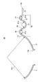
- FIG. 8 is a diagram showing a cross-sectional shape parallel to the sound radiation direction of the diaphragm according to the second example of the present invention.
- the same components as those of the diaphragm 10 of the first embodiment shown in FIG. 6 are indicated by the same reference numerals as those in FIG. A duplicate description of elements is omitted.
- a cross section passing through the center of the diaphragm 70 and parallel to the sound radiating direction is composed of a convex arc section in order from the inner periphery to the outer periphery of the diaphragm 70 with respect to the sound radiating direction.
- the cross sections of the second curved plate 12, the third curved plate 13, and the fourth curved plate 14 that pass through the centers of the diaphragms 70 and are parallel to the sound radiation direction have an arc shape.
- Such an arc shape has a mechanically equivalent structure in any part.
- the force inside the diaphragm 70 caused by the pressure of water around the diaphragm 70 acts evenly on each part of the diaphragm 70, and as a result, the force can be dispersed.
- the first curved plate 11 mainly plays a role of sound radiation, and is a portion composed of the second curved plate 12, the third curved plate 13, the fourth curved plate 14, and the flat ring portion 18 outside thereof. 71 mainly plays the role of an edge.
- the diaphragm 70 of the present embodiment does not have the first inclined portion 15, the second inclined portion 16, and the third inclined portion 17 shown in FIG. 5 and FIG. 11, the 2nd music plate 12, the 3rd music plate 13, and the 4th music plate 14 are connected continuously.
- the diaphragm 70 has such a concavo-convex shape, water resistance in terms of strength that can withstand the pressure of the water flow is further improved. Specifically, a part of the second curved plate 12, the third curved plate 13, and the fourth curved plate 14 is not easily deformed temporarily by a predetermined pressure of the water flow, and even if it is deformed, it can return to a predetermined shape. Is an example.
- the diaphragms 10 and 70 in which the radius of curvature R13 of the curved plate 13 and the radius of curvature R14 of the fourth curved plate 14 are as follows are illustrated.
- the curvature radius R11 of the first curved plate 11 is larger than the curvature radius R13 of the third curved plate 13
- the curvature radius R14 of the fourth curved plate 14 is smaller than the curvature radius R12 of the second curved plate 12
- the radius of curvature R12 of the second curved plate 12 is smaller than the radius of curvature R13 of the third curved plate 13.
- the diaphragm referred to in the present invention is not limited to this, and the magnitude relationship of the curvature radii of the four curved plates may be other than the above.
- the reverse resonance frequency in the speaker device can be shifted to the high frequency side to further suppress the decrease in the reproduction sound pressure of the desired low frequency sound. Is as described above.
Landscapes
- Engineering & Computer Science (AREA)
- Physics & Mathematics (AREA)
- Acoustics & Sound (AREA)
- Signal Processing (AREA)
- Multimedia (AREA)
- Mechanical Engineering (AREA)
- Diaphragms For Electromechanical Transducers (AREA)
- Details Of Audible-Bandwidth Transducers (AREA)
- Audible-Bandwidth Dynamoelectric Transducers Other Than Pickups (AREA)
- Fittings On The Vehicle Exterior For Carrying Loads, And Devices For Holding Or Mounting Articles (AREA)
Abstract
Description
本発明の第1施例にかかるスピーカ装置について図を参照して説明する。図1は、本発明の第1施例にかかるスピーカ装置を音放射先から見た斜視図である。図2は、図1に示されているスピーカ装置を音放射先に対する裏側から見た斜視図である。図3は、図1に示されているスピーカ装置の、音放射方向に沿った断面を示す断面図である。また、図4は、図1に示されているスピーカ装置を、図3に示されている断面が見えるようにカットして示す斜視図である。
つまり、本実施例のスピーカ装置1では、振動板10が、車両に配置され、車両の外部に向けて車両の接近を告げる通報音を発生する。このような通報音のためのスピーカ装置には、高い再生音圧と高い耐熱性や耐水性が必要とされる。本実施例のスピーカ装置1は、上述した高い再生音圧と高い耐熱性や耐水性を有している。
次に、本発明の第2実施例にかかるスピーカ装置について説明する。この第2実施例は、振動板の形状を除いて第1実施例と同等である。そこで、以下では、第2実施例について、第1実施例との相違点に注目して説明を行い、スピーカ装置の構成等の共通点については説明を割愛する。
10,70 振動板
10a 開口
10b 外周縁
11 第1曲板
12 第2曲板
13 第3曲板
14 第4曲板
20 フレーム
30 ダンパ
40 ボイスコイル
50 磁気回路
60 キャップ
R11 第1曲板の曲率半径
R12 第2曲板の曲率半径
R13 第3曲板の曲率半径
R14 第4曲板の曲率半径
Claims (9)
- ポリイミドを含むフィルムから成る振動板と、
前記振動板を支持するフレームと、
を備え、
前記振動板の中心を通り音放射方向に平行な断面は該音放射方向に対して、該振動板の内周部から外周部にわたって順に、
凹の円弧を有する第1曲板と、
凸の円弧を有する第2曲板と、
凹の円弧を有する第3曲板と、
凸の円弧を有する第4曲板と、
を備え、
前記第1曲板の面積は、前記第2曲板、前記第3曲板、及び前記第4曲板のぞれぞれの面積の何れよりも大きいことを特徴とするスピーカ装置。 - 前記第1曲板の円弧の曲率半径が、前記第3曲板の円弧の曲率半径よりも大きく、
前記第2曲板の円弧の曲率半径が、前記第3曲板の円弧の曲率半径よりも小さいことを特徴とする請求項1に記載のスピーカ装置。 - 前記振動板は、
凸の円弧の断面から成る前記第2曲板と、
凹の円弧の断面から成る前記第3曲板と、
凸の円弧の断面から成る前記第4の曲板と、
を備えることを特徴とする請求項1に記載のスピーカ装置。 - 前記第1曲板の中央部に開口が設けられ、該開口が、キャップで覆われており、
前記キャップは、前記振動板の中心を通り音放射方向平行な断面は凹の円弧であることを特徴とする請求項1に記載のスピーカ装置。 - 前記キャップが、ポリイミドを含むフィルムから成ることを特徴とする請求項4に記載のスピーカ装置。
- 前記キャップの円弧の曲率半径が、前記第1曲板の円弧の曲率半径よりも小さいことを特徴とする請求項4に記載のスピーカ装置。
- 前記振動板が、50μm、75μm、100μm、125μmのうちの何れかの厚みを有することを特徴とする請求項1に記載のスピーカ装置。
- 前記振動板が、125μmの厚みを有することを特徴とする請求項1に記載のスピーカ装置。
- 前記振動板が、車両に配置され、該車両の外部に向けて該車両の接近を告げる通報音を発生するものであることを特徴とする請求項1に記載のスピーカ装置。
Priority Applications (4)
| Application Number | Priority Date | Filing Date | Title |
|---|---|---|---|
| PCT/JP2015/050504 WO2016111005A1 (ja) | 2015-01-09 | 2015-01-09 | スピーカ装置 |
| EP15876880.4A EP3244634B1 (en) | 2015-01-09 | 2015-01-09 | Speaker device |
| JP2016568247A JP6449332B2 (ja) | 2015-01-09 | 2015-01-09 | スピーカ装置 |
| US15/542,542 US10231042B2 (en) | 2015-01-09 | 2015-01-09 | Speaker device |
Applications Claiming Priority (1)
| Application Number | Priority Date | Filing Date | Title |
|---|---|---|---|
| PCT/JP2015/050504 WO2016111005A1 (ja) | 2015-01-09 | 2015-01-09 | スピーカ装置 |
Publications (1)
| Publication Number | Publication Date |
|---|---|
| WO2016111005A1 true WO2016111005A1 (ja) | 2016-07-14 |
Family
ID=56355725
Family Applications (1)
| Application Number | Title | Priority Date | Filing Date |
|---|---|---|---|
| PCT/JP2015/050504 Ceased WO2016111005A1 (ja) | 2015-01-09 | 2015-01-09 | スピーカ装置 |
Country Status (4)
| Country | Link |
|---|---|
| US (1) | US10231042B2 (ja) |
| EP (1) | EP3244634B1 (ja) |
| JP (1) | JP6449332B2 (ja) |
| WO (1) | WO2016111005A1 (ja) |
Cited By (2)
| Publication number | Priority date | Publication date | Assignee | Title |
|---|---|---|---|---|
| KR20200045891A (ko) * | 2018-10-23 | 2020-05-06 | 현대자동차주식회사 | 차량용 스피커장치 |
| WO2024114236A1 (zh) * | 2022-12-02 | 2024-06-06 | 苏州上声电子股份有限公司 | 一种汽车行人警示装置 |
Families Citing this family (1)
| Publication number | Priority date | Publication date | Assignee | Title |
|---|---|---|---|---|
| US10200802B1 (en) * | 2017-08-03 | 2019-02-05 | Bose Corporation | Inverted button cap in acoustic transducer |
Citations (7)
| Publication number | Priority date | Publication date | Assignee | Title |
|---|---|---|---|---|
| JPH03104499A (ja) * | 1989-09-19 | 1991-05-01 | Sony Corp | スピーカ装置 |
| JP2002374593A (ja) * | 2001-06-18 | 2002-12-26 | Pioneer Electronic Corp | スピーカ振動板 |
| JP2007060024A (ja) * | 2005-08-22 | 2007-03-08 | Pioneer Electronic Corp | スピーカ用振動部品 |
| JP2007142982A (ja) * | 2005-11-21 | 2007-06-07 | Pioneer Electronic Corp | スピーカ装置 |
| JP2010258538A (ja) * | 2009-04-21 | 2010-11-11 | Onkyo Corp | スピーカー |
| JP2013531430A (ja) * | 2010-06-04 | 2013-08-01 | ビーツ エレクトロニクス エルエルシー | 振動閉じ込めシステム |
| JP5400246B1 (ja) * | 2013-06-10 | 2014-01-29 | ディービーテクノロジー株式会社 | スピーカおよびそのエッジ構造 |
Family Cites Families (9)
| Publication number | Priority date | Publication date | Assignee | Title |
|---|---|---|---|---|
| US3095941A (en) * | 1957-05-09 | 1963-07-02 | Fauthal A Hassan | Loud speaker construction |
| US4759069A (en) * | 1987-03-25 | 1988-07-19 | Sy/Lert System | Emergency signal warning system |
| EP0963136B1 (en) * | 1998-05-08 | 2011-08-31 | Panasonic Corporation | Speaker |
| US6567528B1 (en) * | 1999-11-18 | 2003-05-20 | Harman International Industries, Incorporated | Offset apex spider |
| JP2004136831A (ja) | 2002-10-21 | 2004-05-13 | Takumakkusu:Kk | 音響発生装置および自動車 |
| JP2005318226A (ja) * | 2004-04-28 | 2005-11-10 | Matsushita Electric Ind Co Ltd | 電気音響変換器用振動板およびこれを用いた電気音響変換器ならびにこの電気音響変換器を用いた電子機器および装置 |
| JP2008205974A (ja) * | 2007-02-21 | 2008-09-04 | Sony Corp | スピーカ用振動板 |
| US8588449B2 (en) * | 2009-04-10 | 2013-11-19 | Koninklijke Philips N.V. | Audio driver |
| DE102012020780B4 (de) * | 2012-10-23 | 2022-02-17 | Audi Ag | Kraftfahrzeug |
-
2015
- 2015-01-09 US US15/542,542 patent/US10231042B2/en active Active
- 2015-01-09 WO PCT/JP2015/050504 patent/WO2016111005A1/ja not_active Ceased
- 2015-01-09 JP JP2016568247A patent/JP6449332B2/ja not_active Expired - Fee Related
- 2015-01-09 EP EP15876880.4A patent/EP3244634B1/en not_active Not-in-force
Patent Citations (7)
| Publication number | Priority date | Publication date | Assignee | Title |
|---|---|---|---|---|
| JPH03104499A (ja) * | 1989-09-19 | 1991-05-01 | Sony Corp | スピーカ装置 |
| JP2002374593A (ja) * | 2001-06-18 | 2002-12-26 | Pioneer Electronic Corp | スピーカ振動板 |
| JP2007060024A (ja) * | 2005-08-22 | 2007-03-08 | Pioneer Electronic Corp | スピーカ用振動部品 |
| JP2007142982A (ja) * | 2005-11-21 | 2007-06-07 | Pioneer Electronic Corp | スピーカ装置 |
| JP2010258538A (ja) * | 2009-04-21 | 2010-11-11 | Onkyo Corp | スピーカー |
| JP2013531430A (ja) * | 2010-06-04 | 2013-08-01 | ビーツ エレクトロニクス エルエルシー | 振動閉じ込めシステム |
| JP5400246B1 (ja) * | 2013-06-10 | 2014-01-29 | ディービーテクノロジー株式会社 | スピーカおよびそのエッジ構造 |
Cited By (3)
| Publication number | Priority date | Publication date | Assignee | Title |
|---|---|---|---|---|
| KR20200045891A (ko) * | 2018-10-23 | 2020-05-06 | 현대자동차주식회사 | 차량용 스피커장치 |
| KR102594990B1 (ko) | 2018-10-23 | 2023-10-27 | 현대자동차주식회사 | 차량용 스피커장치 |
| WO2024114236A1 (zh) * | 2022-12-02 | 2024-06-06 | 苏州上声电子股份有限公司 | 一种汽车行人警示装置 |
Also Published As
| Publication number | Publication date |
|---|---|
| EP3244634A1 (en) | 2017-11-15 |
| EP3244634B1 (en) | 2020-05-06 |
| EP3244634A4 (en) | 2018-09-05 |
| JP6449332B2 (ja) | 2019-01-09 |
| JPWO2016111005A1 (ja) | 2017-10-19 |
| US20170374439A1 (en) | 2017-12-28 |
| US10231042B2 (en) | 2019-03-12 |
Similar Documents
| Publication | Publication Date | Title |
|---|---|---|
| JP4439283B2 (ja) | 長円もしくは楕円形のスピーカ装置 | |
| JP6449332B2 (ja) | スピーカ装置 | |
| CN111418218A (zh) | 扬声器、扬声器系统、立体声扬声器系统以及车载用立体声扬声器系统 | |
| JP3874183B2 (ja) | 電気音響変換器用振動板 | |
| US10820111B2 (en) | Acoustic membrane for a loudspeaker and corresponding loudspeaker | |
| JP4386939B2 (ja) | 振動板及びこれを用いたスピーカユニット | |
| JP2009159009A (ja) | スピーカ | |
| JP4790452B2 (ja) | ボイスコイルボビン、およびスピーカ装置 | |
| JP4768823B2 (ja) | スピーカ | |
| JP2021093580A (ja) | ディフューザー、及び、スピーカー | |
| JP4445182B2 (ja) | スピーカ装置 | |
| JP4658087B2 (ja) | スピーカ用エッジおよびスピーカ装置 | |
| US20070223774A1 (en) | Coupled body of speaker apparatus | |
| JP4576991B2 (ja) | 振動板とそれを用いたスピーカ | |
| JP4749402B2 (ja) | 電気音響変換器用振動板 | |
| JP2016082321A (ja) | 電気音響変換器 | |
| JP2005217712A (ja) | ドーム形振動板及びドーム形振動板を備えたスピーカ装置 | |
| JP2008167137A (ja) | スピーカ | |
| JP2008182301A (ja) | スピーカ | |
| KR101836522B1 (ko) | 차량용 경음기의 디스크 | |
| JP2005012694A (ja) | 平面スピーカ | |
| TW202408250A (zh) | 電聲轉換器及頭戴式耳機 | |
| JP2023121437A (ja) | スピーカ | |
| JP2952920B2 (ja) | スピーカ | |
| WO2025126266A1 (ja) | スピーカ装置 |
Legal Events
| Date | Code | Title | Description |
|---|---|---|---|
| 121 | Ep: the epo has been informed by wipo that ep was designated in this application |
Ref document number: 15876880 Country of ref document: EP Kind code of ref document: A1 |
|
| ENP | Entry into the national phase |
Ref document number: 2016568247 Country of ref document: JP Kind code of ref document: A |
|
| WWE | Wipo information: entry into national phase |
Ref document number: 15542542 Country of ref document: US |
|
| NENP | Non-entry into the national phase |
Ref country code: DE |
|
| REEP | Request for entry into the european phase |
Ref document number: 2015876880 Country of ref document: EP |