WO2016111231A1 - 弁尖サイザー - Google Patents
弁尖サイザー Download PDFInfo
- Publication number
- WO2016111231A1 WO2016111231A1 PCT/JP2015/086525 JP2015086525W WO2016111231A1 WO 2016111231 A1 WO2016111231 A1 WO 2016111231A1 JP 2015086525 W JP2015086525 W JP 2015086525W WO 2016111231 A1 WO2016111231 A1 WO 2016111231A1
- Authority
- WO
- WIPO (PCT)
- Prior art keywords
- leaflet
- commissure
- sizer
- leaflet sizer
- arm
- Prior art date
- Legal status (The legal status is an assumption and is not a legal conclusion. Google has not performed a legal analysis and makes no representation as to the accuracy of the status listed.)
- Ceased
Links
Images



Classifications
-
- A—HUMAN NECESSITIES
- A61—MEDICAL OR VETERINARY SCIENCE; HYGIENE
- A61F—FILTERS IMPLANTABLE INTO BLOOD VESSELS; PROSTHESES; DEVICES PROVIDING PATENCY TO, OR PREVENTING COLLAPSING OF, TUBULAR STRUCTURES OF THE BODY, e.g. STENTS; ORTHOPAEDIC, NURSING OR CONTRACEPTIVE DEVICES; FOMENTATION; TREATMENT OR PROTECTION OF EYES OR EARS; BANDAGES, DRESSINGS OR ABSORBENT PADS; FIRST-AID KITS
- A61F2/00—Filters implantable into blood vessels; Prostheses, i.e. artificial substitutes or replacements for parts of the body; Appliances for connecting them with the body; Devices providing patency to, or preventing collapsing of, tubular structures of the body, e.g. stents
- A61F2/02—Prostheses implantable into the body
- A61F2/24—Heart valves ; Vascular valves, e.g. venous valves; Heart implants, e.g. passive devices for improving the function of the native valve or the heart muscle; Transmyocardial revascularisation [TMR] devices; Valves implantable in the body
- A61F2/2496—Devices for determining the dimensions of the prosthetic valve to be implanted, e.g. templates, sizers
-
- A—HUMAN NECESSITIES
- A61—MEDICAL OR VETERINARY SCIENCE; HYGIENE
- A61B—DIAGNOSIS; SURGERY; IDENTIFICATION
- A61B5/00—Measuring for diagnostic purposes; Identification of persons
- A61B5/103—Measuring devices for testing the shape, pattern, colour, size or movement of the body or parts thereof, for diagnostic purposes
- A61B5/107—Measuring physical dimensions, e.g. size of the entire body or parts thereof
- A61B5/1076—Measuring physical dimensions, e.g. size of the entire body or parts thereof for measuring dimensions inside body cavities, e.g. using catheters
Definitions
- the present invention relates to a leaflet sizer for measuring the size of a heart valve.
- the leaflet sizer is used, for example, when forming a leaflet material from an artificial membrane or a biological membrane for a heart valve such as an aortic valvuloplasty or aortic valve reconstruction.
- Japanese Patent No. 5106019 discloses a valve leaflet former.
- This leaflet former has a plurality of leaflet sizers and a template.
- An example of a leaflet sizer is shown in FIG. 2 of this publication. That is, the valve leaflet sizer in this publication has a sizer block and a handle, and the sizer block is formed with an arcuate surface obtained by cutting a cylinder at an angle corresponding to the central angle of the commissure portion. 2). Further, the sizer block is provided with a stylus portion that positions both end portions of the arc surface at the commissure portion.
- the leaflet former disclosed in this publication has a shape in which a plurality of sizes of sizer blocks are respectively connected to a handle.
- Aortic valvuloplasty is introduced in, for example, Shigeyuki Ozaki, “Aortic Valvuloplasty Using Autologous Pericardium”, Artificial Organ, Vol. 39, No. 3, pp. 157-161 (Non-patent Document 1). Also in this document, as described above, a leaflet sizer having a sizer block and a handle is used (for example, FIG. 2).
- Aortic valvuloplasty is an epoch-making treatment method.
- the above-mentioned leaflet former requires a plurality of leaflet sizers. Even if a plurality of leaflet sizers are included in one leaflet former, only one or two leaflet sizers are actually used in one treatment. For this reason, there is a problem that many leaflet sizers are wasted.
- the leaflet former is a disposable medical device. However, as mentioned above, since many leaflet sizers are not used in the operation, the leaflet former may be reused.
- the handle is attached to the main part of the fan at an angle. For this reason, when the conventional leaflet sizer is inserted into the back of the artery, there is a problem that the handle hits the anterior wall of the aorta and it is difficult to insert the sizer deeply.
- an object of the present invention is to provide a leaflet sizer that can prevent a situation where the leaflet sizer is reused.
- the present invention also relates to a leaflet sizer that can be easily inserted into the aorta during a procedure, and the leaflets can be easily sized accordingly.
- the first aspect of the present invention relates to a leaflet sizer (or leaflet sizer set) having a function of a plurality of conventional leaflet sizers with one or a small number of leaflet sizers.
- the valve leaflet sizer has first and second commissure portion indicating portions 11 and 13 applied to two commissure portions in the heart valve. This allows the leaflet sizer to determine the size of the heart valve. And the relative position of the 1st and 2nd commissure part instruction
- the valve leaflet sizer has a first support portion 21 that supports the first commissure unit instruction unit 11.
- the first support portion 21 can be expanded and contracted.
- the leaflet sizer may further include a second support portion 23 that supports the second commissure portion instructing portion 13. Further, the second support portion 23 may be extendable and contractible.
- an indicator corresponding to the distance between the two commissure portions is displayed when the first support portion 21 expands and contracts. It further has an index display unit 25 for performing the above operation.
- An example of the expansion / contraction function in the valve leaflet sizer in which the relative positions of the first and second commissure portion indicating portions 11 and 13 are variable is a valve having a storage portion 27 for storing the first support portion so as to be slidable It has a pointed sizer body.
- valve leaflet sizer further includes a valve leaflet sizer body 31 connected to the first and second commissure portion indicating portions 11 and 13 and a handle 33 connected to the valve leaflet sizer body 31.
- the handle 33 is present at a position close to one of the first and second commissure unit indicating units 11 and 13.
- the leaflet sizer of the present invention may have a first arm 51, a second arm 52, and a connecting fulcrum 53.
- the first arm 51 and the second arm 52 intersect each other in the middle.
- the connection fulcrum part 53 connects the first and second arms 51 and 52 so that they can be opened and closed at the intersection of the first and second arms 51 and 52.
- the first commissure portion instructing portion 11 is provided at the tip of the first arm 51
- the second commissure portion support portion 13 is provided at the tip of the second arm 52. In this way, the relative positions of the first and second commissure unit indicating units 11 and 13 may be variable.
- the leaflet sizer of the present invention may have a base portion 61, a rod 62, a first arm 63, and a second arm 64.
- a rod 62 is inserted into the base portion 61.
- the rod 62 can advance and retreat in the base portion 61 so as to be guided by the base portion 61.
- a first arm 63 and a second arm 64 are connected to the base portion 61.
- the first and second arm parts 63 are configured to open and close in conjunction with an operation in which the rod 62 advances and retracts the base part 61.
- the first commissure portion instructing portion 11 is provided at the tip of the first arm 63
- the second commissure portion support portion 13 is provided at the tip of the second arm 64. In this way, the relative positions of the first and second commissure unit indicating units 11 and 13 may be variable.
- a second aspect of the present invention relates to a leaflet sizer set 17 having a plurality of leaflet sizer heads 15a, 15b, 15c.
- the leaflet sizer heads 15a, 15b, and 15c have first and second commissure portion indicating portions 11a and 13a applied to two commissure portions in the heart valve, respectively, and medical for determining the size of the heart valve Equipment.
- the plurality of leaflet sizer heads 15a, 15b, and 15c are different from each other in the relative positions of the first and second commissure portion indicating portions. That is, the leaflet sizer set 17 has a plurality of leaflet sizer heads.
- Each of the plurality of leaflet sizers has connection holes 41a, 41b, and 41c for connecting the plurality of leaflet sizer heads.
- the plurality of leaflet sizer heads are bound by a binding body 43 penetrating the connection holes. It is united.
- the leaflet sizer according to the first aspect of the present invention is one or a small number of leaflet sizers and has the functions of a plurality of conventional leaflet sizers. For this reason, the leaflet sizer discarded without being used at all can be reduced. As a result, it is possible to prevent an attempt to reuse the leaflet sizer.
- the handle close to one commissure support part is located closer to the aortic wall than the conventional sizer, so when inserting the sizer into the aorta, The handle becomes difficult to hit, and as a result, the sizer can be easily inserted deep into the aorta.
- the leaflet sizer according to the second aspect of the present invention has a plurality of sizers integrated with each other, it is difficult to dispose only a part of the size even if some sizers are used. For this reason, it can prevent trying to reuse a leaflet sizer.
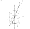
- FIG. 1 is a conceptual diagram showing an example of a leaflet sizer of the present invention.
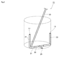
- FIG. 2 is a conceptual diagram showing an example of the leaflet sizer of the present invention.
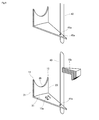
- FIG. 3 is a conceptual diagram showing an example of a leaflet sizer of the present invention.
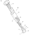
- FIG. 4 is a conceptual diagram showing an example of a leaflet sizer of the present invention.
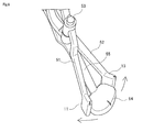
- FIG. 5 is a perspective view showing an example of the appearance of a cross-opening / closing type leaflet sizer.
- FIG. 6 is an enlarged view showing a state in which the cross-opening / closing valve leaflet sizer is closed.
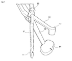
- FIG. 7 is an enlarged view showing a state in which a cross-opening / closing valve leaflet sizer is opened.
- FIG. 1 is a conceptual diagram showing an example of a leaflet sizer of the present invention.
- FIG. 2 is a conceptual diagram showing an example of the leaflet sizer of the present invention.
- FIG. 3 is a conceptual diagram showing
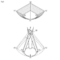
- FIG. 8 is a schematic diagram showing the operating range of a cross-opening / closing type valve leaflet sizer.
- FIG. 9 is a perspective view showing a state in which a rod opening / closing type leaflet sizer is closed.
- FIG. 10 is a perspective view showing a state in which a rod opening / closing type leaflet sizer is opened.
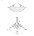
- FIG. 11 is a schematic diagram showing an operation range of a rod opening / closing type leaflet sizer.
- the first aspect of the present invention relates to a leaflet sizer having a function of a plurality of conventional leaflet sizers with one or a small number of leaflet sizers.
- the leaflet sizer is disclosed in the above-mentioned Patent Document 1 (Japanese Patent No. 5106019) and Non-Patent Document 1 (Shigeyuki Ozaki “Aortic Valvuloplasty Using Self-Pericardium” Artificial Organ Vol.3 No.3, pages 157-161. It is a known medical device as disclosed on page.
- FIG. 1 is a conceptual diagram showing an example of a leaflet sizer of the present invention.
- the leaflet sizer has first and second commissure portion indicating portions 11 and 13 applied to two commissure portions in the heart valve. These 1st and 2nd commissure part instruction
- indication parts 11 and 13 are corresponded to the stylus part in patent document 1 (patent No. 5106019).
- indication parts 11 and 13 are the parts for inserting into the excised valve ring part in the case of a treatment, and pointing to the commissure part located in both ends, respectively.
- the leaflet sizer can determine the size of the heart valve by means of the first and second commissure portion instruction units 11 and 13. And the relative position of the 1st and 2nd commissure part instruction
- the valve leaflet sizer has a first support portion 21 that supports the first commissure unit instruction unit 11.
- the first support portion 21 can be expanded and contracted.
- the leaflet sizer may further include a second support portion 23 that supports the second commissure portion instructing portion 13. Further, the second support portion 23 may be extendable and contractible. Expansion and contraction means that the relative positions of the first and second commissure unit indicating units 11 and 13 are variable.
- an indicator corresponding to the distance between the two commissure portions is displayed when the first support portion 21 expands and contracts.
- It further has an index display unit 25 for performing the above operation.
- the accommodating part 27 it has the apparatus which measures the edge part which exists in the accommodating part 27 among the valve leaflet sizer main bodies 31, and this measures the position of an edge part, The 1st and 2nd commissure
- the relative positions of the part instruction units 11 and 13 may be grasped, and the grasped relative positions may be displayed on the indicator display unit 25.
- An example of an expansion / contraction function in the leaflet sizer in which the relative positions of the first and second commissure portion indicating portions 11 and 13 are variable includes a storage portion 27 for storing the first support portion 21 so as to be slidable.
- a valve leaflet sizer body 31 is provided. The leaflet sizer main body 31 can change the relative positions of the first and second commissure portion indicating portions 11 and 13 by sliding inside the accommodating portion 27.
- valve leaflet sizer further includes a valve leaflet sizer body 31 connected to the first and second commissure portion indicating portions 11 and 13 and a handle 33 connected to the valve leaflet sizer body 31.
- the handle 33 is present at a position close to one of the first and second commissure unit indicating units 11 and 13.
- x 3 is 0 or more and 0.4 x 2 or less. preferably it may be 0 or 0.3x 2 or less, may be 0 or 0.2x 2 or less, may be 0 or 0.1x 2 or less.
- x 3 can be a 0.05X 2 or 0.3x 2 or less, even in 0.1x 2 or more 0.2x 2 or less Good.
- the portion of the handle 33 that contacts the housing part 27 or the leaflet sizer main body 31 may be the center of the housing body 27 or the leaflet sizer body 31, in which case the handle is the first and second commissure part indicating parts. What inclines toward either 11 or 13 is preferable.
- a preferred example of a leaflet sizer is one in which a mark 29 is present at the center of the edge. This mark will be useful for marking during the procedure.
- the sizer body 31 is present at the edge of the cylinder. And it has the structure where the 1st and 2nd support parts 21 and 23 bent upwards from the both ends (or near both ends) of the edge part.
- indication part 11 and the 1st support part 21 exist in the left side from the center of the main-body part in FIG. 1, and the 2nd commissure part instruction
- the part which exists in an edge part among the 1st and 2nd support parts 21 and 23 is accommodated in the accommodating part 27 partially or entirely.
- the accommodating portion 27 has a cylindrical body having an inner diameter equal to or larger than the outer shape of the edge portion so that the edge portion of the first and second support portions 21 and 23 can be accommodated.
- the above example of the expansion and contraction function in the leaflet sizer in which the relative positions of the first and second commissure portion indicating portions 11 and 13 are variable is the first support portion 21 and the second support portion.
- the edge portion has a spring structure, a bellows structure, and an elastic body.
- An example of the elastic body is rubber.
- the first support 21 accommodated in the accommodating portion 27 moves in the left direction (or right direction) in FIG. 1, and the first and second commissure portion indicating portions 11 are moved. , 13 is widened.
- the preferable example shown in FIG. 1 is that when the first support 21 moves in the left direction or the right direction in FIG. 1, the second support 23 moves in the opposite direction to the first support 21. Is. This can be realized by a mechanism in which the second support 23 moves in the opposite direction when the first support 21 moves.
- first support part 21 and the second support part are hollow, and the connecting part 30 is inserted into the hollow part. And either or both of the 1st support part 21 and the 2nd support part can slide on a connection part. In this way, the relative positions of the first and second commissure unit indicating units 11 and 13 can be adjusted.
- a bar for a mark 29 for indicating the center extends from the center of the connecting portion 30.
- each element is described as a rod.
- the first and second support portions 21 and 23 since the first and second support portions 21 and 23 are located outside the connecting portion 30, the first and second support portions 21 and 23 have a smooth structure (thickening). Structure). For this reason, in this example, it becomes easy to take a three-dimensional shape that facilitates actual treatment.
- the first and second support portions 21 and 23 can be shaped along the inner wall of the blood vessel.
- a second aspect of the present invention relates to a leaflet sizer set 17 having a plurality of leaflet sizer heads 15a, 15b, 15c.
- the leaflet sizer heads 15a, 15b, and 15c have first and second commissure portion indicating portions 11a and 13a applied to two commissure portions in the heart valve, respectively, and medical for determining the size of the heart valve Equipment.
- the plurality of leaflet sizer heads 15a, 15b, and 15c are different from each other in the relative positions of the first and second commissure portion indicating portions. That is, the leaflet sizer has a plurality of leaflet sizer heads.
- Each of the plurality of leaflet sizers has connection holes 41a, 41b, and 41c for connecting the plurality of leaflet sizer heads.
- the plurality of leaflet sizer heads are bound by a binding body 43 penetrating the connection holes. It is united.
- FIG. 3 is a conceptual diagram showing a leaflet sizer.
- a plurality of leaflet sizer heads 15a, 15b, and 15c are connected so as to be rotatable about the constraining body 43 as an axis.
- a handle 33 is formed on the upper part of the binding body.
- the valve leaflet sizer head 15b is rotated around the constraining body 43 using the connection hole 41b. Let Then, only the desired leaflet sizer head 15b can be taken out.
- the remaining leaflet sizer heads are also axially fixed to the constraining body 43 through the connection holes 41a and 43c.
- the remaining leaflet sizer heads 15a and 15c act to hold the artery and the like and to measure the leaflet size during the actual operation.
- FIG. 4 is a conceptual diagram showing a leaflet sizer.
- the leaflet sizer shown in FIG. 4 has a plurality of leaflet sizer heads 15a, 15b, and 15c. And each leaflet sizer head 15a, 15b, 15c has the 1st and 2nd commissure part instruction
- the plurality of leaflet sizer heads 15a, 15b, and 15c have different relative positions of the first and second commissure portion indicating sections. That is, the leaflet sizer has a plurality of leaflet sizer heads.
- Each of the plurality of leaflet sizers has a connection hole 41a for connecting the plurality of leaflet sizer heads, and the plurality of leaflet sizer heads are integrated by a constraining body 43 penetrating the connection hole. Yes.
- the size of the leaflet sizer head is indicated, and the leaflet size can be understood in actual measurement.
- each leaflet sizer head has a fixing hole 45a. By passing one end of the loop-shaped binding body 43 through the fixing hole 45a, the binding body 43 can be used as a handle.
- FIGS. 5, 6, 7, and 8 The leaflet sizer shown in FIGS. 5 to 8 is referred to as a “cross-opening / closing type leaflet sizer” in the present specification.
- the cross-opening / closing valve leaflet sizer has a first arm 51 and a second arm 52 that intersect each other. At the tip of the first arm 51, the first commissure part instructing unit 11 is provided, and at the tip of the first arm 62, the second commissure part instructing unit 13 is provided.
- a connecting fulcrum 53 is formed at the intersection of the first arm 51 and the second arm 52.
- the connection fulcrum 53 connects the first arm 51 and the second arm 52 so that they can be opened and closed.
- the connection fulcrum portion 53 may be configured by a pin that passes through the intersection of the first arm 51 and the second arm 52. Note that “openable and closable” means that the relative positions of the tips of the first and second arms 51 and 52 (that is, the first and second communicator instruction units 11 and 13) are variable.
- the leaflet sizer has a head 54 between the first commissure section instruction section 11 and the first commissure section instruction section 13. As shown in FIG. 5, in a state where the first and second commissure portion indicating portions 11 and 13 are closed, it is preferable that these indicating portions 11 and 13 abut on the side surface of the head 54.
- the head 54 is attached to the tip of the third arm 55.
- the third arm 55 is connected to the first arm 51 and the second arm 52 by a connection fulcrum 53.
- the third arm 55 is basically immobile. That is, the first arm 51 and the second arm 52 are opened and closed so as to move to the left and right of the stationary third arm 55 with the connection fulcrum 53 as a fulcrum.
- the relative position of the first arm 51 (first communicator instruction unit 11) and the second arm 52 (second communicator instruction unit 13) with the third arm 55 (head 54) as the center. Can be changed.
- the cross-opening / closing type leaflet sizer includes a handle 33 and a guide 56.
- the handle 33 serves as a grip when the operator has a leaflet sizer.
- a part of the handle 33 is inserted into the guide 56.
- a part of the handle 33 that enters the guide 56 is formed with a screw thread, and is fitted into a screw hole formed in the guide 56. For this reason, a part of the handle 33 can be advanced deeply into the guide 56 by screwing the handle 33 in a fixed direction, while one part of the handle 33 can be driven by screwing the handle 33 in the opposite direction. The part can be pulled out from the inside of the guide 56.
- the first arm 51, the second arm 52, and the third arm 55 are inserted into the guide 56 from the side opposite to the handle 33.
- the first to third arms 51, 52, 55 are inserted into the guide 56 at the other end side opposite to the tips provided with the instruction units 11, 13 and the head 54. It becomes a state.
- the other ends of the first to third arms 51, 52, 55 are connected to a part of the handle 33.
- at least a portion of the first and second arms 51 and 52 inserted into the guide 56 is formed of a flexible material that is curved by applying a pressing force.
- the entire first and second arms 51 and 52 can be formed of a flexible material. Therefore, when the handle 33 is screwed and a part of the handle 33 is advanced deeply into the guide 56, the first and second arms 51 and 52 are bent inside the guide 56 according to the pressing force. .
- a projecting slide pin 57 is formed at a portion of the first and second arms 51 and 52 inserted into the guide 56.
- the guide 56 is formed with a rail 58 for guiding the slide pin 57.
- the rail 58 is a cut (slit) formed in the guide 56.
- the rail 58 may be a groove formed in the guide 56.
- the rail 58 is provided so as to be inclined at a predetermined angle with respect to the direction in which the handle 56 advances and retreats.
- a rail 58 for guiding the slide pin 57 formed on the first arm 51 and a slide pin (not shown) formed on the second arm 52 are guided.
- the rails are inclined in the opposite direction, that is, in the intersecting direction. Accordingly, when the handle 33 is gradually advanced into the guide 56, the first arm 51 and the second arm 52 are guided by the rail 58, and their relative positions gradually move away from each other. . By urging the relative positions of the other ends of the first and second arms 51 and 52 in this way, the first and second provided on the distal end side with the connection fulcrum 53 as a fulcrum. The relative positions of the commissure instruction units 11 and 13 are also separated. On the other hand, in order to bring the relative positions of the first and second commissure unit instruction units 11 and 13 closer, an operation opposite to the above-described operation may be performed. Thereby, the relative position of the 1st and 2nd commissure part instruction
- FIG. 6 shows the closed state of the distal ends of the first and second arms 51 and 52, that is, the first and second commissure section indicating sections 11 and 13.
- FIG. 7 shows a state in which the tips of the first and second arms 51 and 52, that is, the first and second commissure portion instruction units 11 and 13 are opened.
- the first and second arms 51 and 52 gradually expand from the closed state shown in FIG. 6 to the open state shown in FIG. For this reason, the size of the heart valve can be measured by applying it to the commissural part of the heart valve of the patient while adjusting the positional relationship between the first and second commissural part instruction units 11 and 13.
- FIG. 8 shows the relative positions of the first commissure section instructing section 11, the second commissure section instructing section 13, and the head 54 as the first and second arms 51 and 52 are opened and closed.
- the change is shown schematically.
- the position of the vertex of the head 54 is indicated by reference numeral P ⁇ b> 1
- the position of the vertex of the first commissure support part 11 is indicated by reference numeral P ⁇ b> 2
- the position of the vertex of the second commissure part instruction part 13 is indicated by reference sign This is indicated by P3.
- the cross-opening and closing type valve leaflet sizer causes the first and second commissure portion indicating portions 11 and 13 to be connected to the connecting fulcrum portion.
- FIGS. 9 to 11 The leaflet sizer shown in FIGS. 9 to 11 is referred to as a “rod opening / closing type leaflet sizer” in the present specification.
- the rod opening / closing type leaflet sizer has a base portion 61 for supporting the rod 62 so as to be able to advance and retract.
- the base portion 61 is fixed to the tip of a rod-shaped handle 33, for example.
- the base portion 61 has a through hole penetrating in the vertical direction inside, and a rod 62 is inserted into the through hole.
- the rod 62 is guided by the base portion 61 and moves up and down.
- a first arm 63 and a second arm 64 are connected to the outside of the base portion 61. Further, of the first and second arms 63, 63, the first commissure part indicating part 11 and the second commissure part indicating part are respectively provided at the tips opposite to the connecting end with respect to the base part 61. 13 is attached. Further, in the present embodiment, a third arm 65 is connected to the outside of the base portion 61, and the third arm 65 is located between the first arm 63 and the second arm 64. . A head 66 is attached to the tip of the third arm 65.
- the rod opening / closing type leaflet sizer has an interlocking mechanism (not shown) for interlocking the rod 62 and the first to third arms 63, 64, 65.
- an interlocking mechanism can be appropriately designed by those skilled in the art and is not particularly limited. That is, as shown in FIGS. 9 and 10, the interlocking mechanism interlocks the advance / retreat operation of the rod 62 and the opening / closing operations of the first to third arms 63, 64, 65.
- the first to third arms 63, 64, 65 are closed.
- the first to third arms 63, 64, 65 are opened.
- the relative positions of the first commissure unit instruction unit 11 and the second commissure unit instruction unit 13 are separated.
- the open / close state of the first to third arms 63, 64, 65 can be freely adjusted by moving the rod 62 back and forth.
- the size of the heart valve can be measured by applying it to the commissural part of the heart valve of the patient while adjusting the positional relationship between the first and second commissural part instruction units 11 and 13.
- FIG. 11 schematically shows how the relative positions of the first commissure portion instructing section 11, the second commissure section instructing section 13, and the head 66 change in a rod opening / closing type valve leaflet sizer.
- the position of the vertex of the head 66 is indicated by reference numeral P ⁇ b> 1
- the position of the vertex of the first commissure support part 11 is indicated by reference numeral P ⁇ b> 2
- the position of the vertex of the second commissure part instruction unit 13 is indicated by reference sign This is indicated by P3.
- P 1, P 2, and P 3 are located on the circumference centering on the connection fulcrum 33.
- the rod opening / closing type leaflet sizer has a uniform expansion width of P1, P2 and P3. That is, the distance from P1 to P1 ′, the distance from P2 to P2 ′, and the distance from P3 to P3 ′ are always equal.
- the operator can measure the size of the leaflet assuming a similar fan shape.
- aortic reconstruction in which an aortic valve is formed using a leaflet material formed from the patient's own pericardium will be described.
- a median sternotomy is performed after exposing the sternum.
- extracorporeal circulation with cardiopulmonary bypass is performed.
- the aortic valve is exposed.
- the previously acquired pericardium is expanded and fixed with a thread and immersed in a tissue fixing solution (for example, a solution containing glutaraldehyde).
- a leaflet is formed using the obtained leaflet material.
- the basic operation of a specific treatment method is the same as that of Japanese Patent No. 5106019. That is, using an index formed at a position corresponding to the center point of the leaflet as a mark, a thread is applied to the position indicated by the index, and the center point is stitched. Sewing toward the commissure using this center point as a reference. In the lower end region of the valve leaflet base 25, it is preferable to make the interval between the needles fine.
- the present invention can be used in the field of medical equipment.
Landscapes
- Health & Medical Sciences (AREA)
- Life Sciences & Earth Sciences (AREA)
- Animal Behavior & Ethology (AREA)
- Oral & Maxillofacial Surgery (AREA)
- Veterinary Medicine (AREA)
- Public Health (AREA)
- Engineering & Computer Science (AREA)
- Biomedical Technology (AREA)
- Heart & Thoracic Surgery (AREA)
- General Health & Medical Sciences (AREA)
- Cardiology (AREA)
- Biophysics (AREA)
- Surgery (AREA)
- Molecular Biology (AREA)
- Medical Informatics (AREA)
- Pathology (AREA)
- Physics & Mathematics (AREA)
- Dentistry (AREA)
- Transplantation (AREA)
- Vascular Medicine (AREA)
- Prostheses (AREA)
Abstract
Description
15…弁尖サイザー 21…第1の指示部
25…指標表示部 27…収容部
31…弁尖サイザー本体 33…ハンドル
51…第1のアーム 52…第2のアーム
53…連結支点部 61…ベース部
62…ロッド部 63…第1のアーム
64…第2のアーム
Claims (8)
- 心臓弁における2つの交連部に当てられる第1及び第2の交連部指示部(11,13)を有し,前記心臓弁のサイズを決定するための弁尖サイザー(15)であって,
第1及び第2の交連部指示部の相対位置が可変である弁尖サイザー。 - 請求項1に記載の弁尖サイザーであって,
前記第1の交連部指示部を支える第1の支持部(21)を有し,
第1の支持部は,伸縮可能である,
弁尖サイザー。 - 請求項2に記載の弁尖サイザーであって,
前記第1の支持部(21)が伸縮した際に,前記2つの交連部の距離に対応した指標を表示する指標表示部(25)を更に有する,
弁尖サイザー。 - 請求項2に記載の弁尖サイザーであって,
第1の支持部(21)をスライドできるように収容するための収容部(27)を有する弁尖サイザー本体を有する,
弁尖サイザー。 - 請求項1に記載の弁尖サイザーであって,
第1及び第2の交連部指示部(11,13)と接続された弁尖サイザー本体(31)と,
前記弁尖サイザー本体(31)に接続されたハンドル(33)を,更に有し
前記ハンドル(33)は,第1及び第2の交連部指示部(11,13)の一方に近接した位置に存在する,弁尖サイザー, - 請求項1に記載の弁尖サイザーであって,
第1のアーム(51)と,
第2のアーム(52)と,
第1及び第2のアーム(51,52)の交差点において,第1及び第2のアーム(51,52)を開閉可能に連結する連結支点部(53)と,を更に有し,
前記第1の交連部指示部(11)は,第1のアーム(51)の先端に設けられ,
前記第2の交連部支持部(13)は,第2のアーム(52)の先端に設けられている,
弁尖サイザー。 - 請求項1に記載の弁尖サイザーであって,
ベース部(61)と,
前記ベース部(61)に差し込まれ,前記ベース部(61)の内部を進退可能なロッド(62)と,
前記ベース部(61)に連結され,前記ロッド(62)の進退に伴って開閉する第1のアーム(63)及び第2のアーム(64)と,を更に有し,
前記第1の交連部指示部(11)は,第1のアーム(63)の先端に設けられ,
前記第2の交連部支持部(13)は,第2のアーム(64)の先端に設けられている,
弁尖サイザー。 - 心臓弁における2つの交連部に当てられる第1及び第2の交連部指示部(11a,11b,11c,13a,13b,13c)を有し,前記心臓弁のサイズを決定するための弁尖サイザーヘッド(15a,15b,15c)を複数有し,前記複数の弁尖サイザーヘッド(15a,15b,15c)は,それぞれ第1及び第2の交連部指示部の相対位置が異なっている,弁尖サイザーセット(17)であって,
前記複数の弁尖サイザーのそれぞれは,前記複数の弁尖サイザーを連結するための連結穴(41a,41b,41c)を有し,
前記複数の弁尖サイザーは,前記連結穴を貫通する束縛体(43)により一体とされている,
弁尖サイザーセット。
Priority Applications (4)
| Application Number | Priority Date | Filing Date | Title |
|---|---|---|---|
| EP15877103.0A EP3243484A4 (en) | 2015-01-06 | 2015-12-28 | Leaflet sizer |
| JP2016568353A JP6697400B2 (ja) | 2015-01-06 | 2015-12-28 | 弁尖サイザー |
| BR112017014645-2A BR112017014645B1 (pt) | 2015-01-06 | 2015-12-28 | Medidor de tamanho de folheto |
| US15/642,535 US20170304052A1 (en) | 2015-01-06 | 2017-07-06 | Leaflet sizer |
Applications Claiming Priority (2)
| Application Number | Priority Date | Filing Date | Title |
|---|---|---|---|
| JP2015-001193 | 2015-01-06 | ||
| JP2015001193 | 2015-01-06 |
Related Child Applications (1)
| Application Number | Title | Priority Date | Filing Date |
|---|---|---|---|
| US15/642,535 Continuation US20170304052A1 (en) | 2015-01-06 | 2017-07-06 | Leaflet sizer |
Publications (1)
| Publication Number | Publication Date |
|---|---|
| WO2016111231A1 true WO2016111231A1 (ja) | 2016-07-14 |
Family
ID=56355925
Family Applications (1)
| Application Number | Title | Priority Date | Filing Date |
|---|---|---|---|
| PCT/JP2015/086525 Ceased WO2016111231A1 (ja) | 2015-01-06 | 2015-12-28 | 弁尖サイザー |
Country Status (5)
| Country | Link |
|---|---|
| US (1) | US20170304052A1 (ja) |
| EP (1) | EP3243484A4 (ja) |
| JP (1) | JP6697400B2 (ja) |
| BR (1) | BR112017014645B1 (ja) |
| WO (1) | WO2016111231A1 (ja) |
Cited By (1)
| Publication number | Priority date | Publication date | Assignee | Title |
|---|---|---|---|---|
| JP6484749B1 (ja) * | 2018-10-25 | 2019-03-13 | 重之 尾崎 | 弁尖サイザー |
Families Citing this family (1)
| Publication number | Priority date | Publication date | Assignee | Title |
|---|---|---|---|---|
| JP5738461B1 (ja) * | 2014-09-08 | 2015-06-24 | 重之 尾崎 | 弁尖サイザー |
Citations (2)
| Publication number | Priority date | Publication date | Assignee | Title |
|---|---|---|---|---|
| WO2014114794A2 (en) * | 2013-01-25 | 2014-07-31 | Medtentia International Ltd Oy | A medical device and method for facilitating selection of an annuloplasty implant |
| US20150005671A1 (en) * | 2013-06-28 | 2015-01-01 | Edwards Lifesciences Corporation | Covered heart valve sizer |
Family Cites Families (6)
| Publication number | Priority date | Publication date | Assignee | Title |
|---|---|---|---|---|
| FR2543834B1 (fr) * | 1983-04-07 | 1985-08-23 | Descartes Universite Rene | Sonde a geometrie variable pour la mesure des contraintes radiales dans un sphincter d'un organisme vivant |
| US5885228A (en) * | 1996-05-08 | 1999-03-23 | Heartport, Inc. | Valve sizer and method of use |
| US6598307B2 (en) * | 1999-11-17 | 2003-07-29 | Jack W. Love | Device and method for assessing the geometry of a heart valve |
| WO2001050985A1 (en) * | 2000-01-14 | 2001-07-19 | Viacor Incorporated | Tissue annuloplasty band and apparatus and method for fashioning, sizing and implanting the same |
| US8449625B2 (en) * | 2009-10-27 | 2013-05-28 | Edwards Lifesciences Corporation | Methods of measuring heart valve annuluses for valve replacement |
| US8728013B2 (en) * | 2009-03-18 | 2014-05-20 | Contipi Medical Ltd. | Device and method for fitting a pessary |
-
2015
- 2015-12-28 EP EP15877103.0A patent/EP3243484A4/en not_active Withdrawn
- 2015-12-28 JP JP2016568353A patent/JP6697400B2/ja not_active Expired - Fee Related
- 2015-12-28 WO PCT/JP2015/086525 patent/WO2016111231A1/ja not_active Ceased
- 2015-12-28 BR BR112017014645-2A patent/BR112017014645B1/pt not_active IP Right Cessation
-
2017
- 2017-07-06 US US15/642,535 patent/US20170304052A1/en not_active Abandoned
Patent Citations (2)
| Publication number | Priority date | Publication date | Assignee | Title |
|---|---|---|---|---|
| WO2014114794A2 (en) * | 2013-01-25 | 2014-07-31 | Medtentia International Ltd Oy | A medical device and method for facilitating selection of an annuloplasty implant |
| US20150005671A1 (en) * | 2013-06-28 | 2015-01-01 | Edwards Lifesciences Corporation | Covered heart valve sizer |
Non-Patent Citations (1)
| Title |
|---|
| See also references of EP3243484A4 * |
Cited By (2)
| Publication number | Priority date | Publication date | Assignee | Title |
|---|---|---|---|---|
| JP6484749B1 (ja) * | 2018-10-25 | 2019-03-13 | 重之 尾崎 | 弁尖サイザー |
| WO2020085112A1 (ja) * | 2018-10-25 | 2020-04-30 | 重之 尾崎 | 弁尖サイザー |
Also Published As
| Publication number | Publication date |
|---|---|
| EP3243484A4 (en) | 2018-07-25 |
| BR112017014645A2 (ja) | 2018-12-26 |
| EP3243484A1 (en) | 2017-11-15 |
| BR112017014645B1 (pt) | 2022-05-10 |
| JP6697400B2 (ja) | 2020-05-20 |
| JPWO2016111231A1 (ja) | 2018-07-26 |
| US20170304052A1 (en) | 2017-10-26 |
Similar Documents
| Publication | Publication Date | Title |
|---|---|---|
| JP6411043B2 (ja) | 弁尖形成用テンプレート | |
| US10898176B2 (en) | Tissue retractor | |
| RU2669464C2 (ru) | Медицинское устройство и способ для облегчения выбора имплантата для аннулопластики | |
| JP6595210B2 (ja) | 大動脈弁再建術トレーニングキット | |
| US20090192603A1 (en) | Adjustable Sizer Devices for Minimally Invasive Cardiac Surgery | |
| EP2693986B1 (en) | Compressible heart valve annulus sizing templates | |
| US20120271336A1 (en) | System and method for measuring a vessel in a vascular environment | |
| US20090171363A1 (en) | Automated insertion device for heart valve prosthesis | |
| JP2012517278A (ja) | ロボットによる心臓弁輪サイザー | |
| EP2967921B1 (en) | Dynamic annuloplasty ring sizer | |
| JP6601812B2 (ja) | 関節置換術用手術具 | |
| JP2006501952A (ja) | 測定用構造体を備える外科用縫合装置 | |
| JP2023536687A (ja) | マイクロ手術処置のためのロボットシステム | |
| WO2013065036A2 (en) | A system and method for assisting the positioning of medical instruments | |
| CN107080587A (zh) | 用于椎间盘突出髓核摘除和纤维环缝合的机械臂及机器人 | |
| JP6697400B2 (ja) | 弁尖サイザー | |
| CN103892873A (zh) | 关节镜下前交叉韧带重建的股骨隧道定位器 | |
| Chung et al. | An affordable microsurgical training system for a beginning neurosurgeon: how to realize the self-training laboratory | |
| US6342069B1 (en) | Surgical instruments utilized to assemble a stentless autologous tissue heart valve | |
| CN208876910U (zh) | 一种骨骼内植物植入用定位导向装置 | |
| RU185140U1 (ru) | Изогнутые по ребру ножницы с зондом на нижнем конце для вскрытия сегментарных бронхов | |
| RU2690914C1 (ru) | Набор инструментов для анастомозирования сосудов | |
| RU52565U1 (ru) | Хирургический инструмент | |
| JP2017205347A (ja) | 乳房輪郭測定器具および乳房測定器具のセット | |
| CN121774656A (zh) | 一种眼球前段定位器 |
Legal Events
| Date | Code | Title | Description |
|---|---|---|---|
| 121 | Ep: the epo has been informed by wipo that ep was designated in this application |
Ref document number: 15877103 Country of ref document: EP Kind code of ref document: A1 |
|
| DPE1 | Request for preliminary examination filed after expiration of 19th month from priority date (pct application filed from 20040101) | ||
| ENP | Entry into the national phase |
Ref document number: 2016568353 Country of ref document: JP Kind code of ref document: A |
|
| REEP | Request for entry into the european phase |
Ref document number: 2015877103 Country of ref document: EP |
|
| NENP | Non-entry into the national phase |
Ref country code: DE |
|
| REG | Reference to national code |
Ref country code: BR Ref legal event code: B01A Ref document number: 112017014645 Country of ref document: BR |
|
| REG | Reference to national code |
Ref country code: BR Ref legal event code: B01E Ref document number: 112017014645 Country of ref document: BR |
|
| REG | Reference to national code |
Ref country code: BR Ref legal event code: B01E Ref document number: 112017014645 Country of ref document: BR Free format text: SOLICITA-SE REGULARIZAR O DOCUMENTO DE CESSAO DO DIREITO DE PRIORIDADE APRESENTADO, REFERENTE A PRIORIDADE JP2015-001193, UMA VEZ QUE NAO CONSTAM AS DEVIDAS ASSINATURAS. |
|
| ENP | Entry into the national phase |
Ref document number: 112017014645 Country of ref document: BR Kind code of ref document: A2 Effective date: 20170706 |