WO2016111453A1 - 컴퓨터가 꺼진 상태에서 대기전원부 냉각시키는 팬 제어회로를 갖춘 컴퓨터용 전원공급장치 및 운영방법 - Google Patents
컴퓨터가 꺼진 상태에서 대기전원부 냉각시키는 팬 제어회로를 갖춘 컴퓨터용 전원공급장치 및 운영방법 Download PDFInfo
- Publication number
- WO2016111453A1 WO2016111453A1 PCT/KR2015/012257 KR2015012257W WO2016111453A1 WO 2016111453 A1 WO2016111453 A1 WO 2016111453A1 KR 2015012257 W KR2015012257 W KR 2015012257W WO 2016111453 A1 WO2016111453 A1 WO 2016111453A1
- Authority
- WO
- WIPO (PCT)
- Prior art keywords
- computer
- power supply
- temperature
- current
- fan
- Prior art date
- Legal status (The legal status is an assumption and is not a legal conclusion. Google has not performed a legal analysis and makes no representation as to the accuracy of the status listed.)
- Ceased
Links
Images

Classifications
-
- G—PHYSICS
- G06—COMPUTING OR CALCULATING; COUNTING
- G06F—ELECTRIC DIGITAL DATA PROCESSING
- G06F1/00—Details not covered by groups G06F3/00 - G06F13/00 and G06F21/00
- G06F1/16—Constructional details or arrangements
- G06F1/20—Cooling means
- G06F1/206—Cooling means comprising thermal management
-
- G—PHYSICS
- G06—COMPUTING OR CALCULATING; COUNTING
- G06F—ELECTRIC DIGITAL DATA PROCESSING
- G06F1/00—Details not covered by groups G06F3/00 - G06F13/00 and G06F21/00
- G06F1/16—Constructional details or arrangements
- G06F1/20—Cooling means
-
- G—PHYSICS
- G06—COMPUTING OR CALCULATING; COUNTING
- G06F—ELECTRIC DIGITAL DATA PROCESSING
- G06F1/00—Details not covered by groups G06F3/00 - G06F13/00 and G06F21/00
-
- G—PHYSICS
- G06—COMPUTING OR CALCULATING; COUNTING
- G06F—ELECTRIC DIGITAL DATA PROCESSING
- G06F1/00—Details not covered by groups G06F3/00 - G06F13/00 and G06F21/00
- G06F1/16—Constructional details or arrangements
- G06F1/20—Cooling means
- G06F1/203—Cooling means for portable computers, e.g. for laptops
-
- G—PHYSICS
- G06—COMPUTING OR CALCULATING; COUNTING
- G06F—ELECTRIC DIGITAL DATA PROCESSING
- G06F1/00—Details not covered by groups G06F3/00 - G06F13/00 and G06F21/00
- G06F1/26—Power supply means, e.g. regulation thereof
-
- G—PHYSICS
- G06—COMPUTING OR CALCULATING; COUNTING
- G06F—ELECTRIC DIGITAL DATA PROCESSING
- G06F1/00—Details not covered by groups G06F3/00 - G06F13/00 and G06F21/00
- G06F1/26—Power supply means, e.g. regulation thereof
- G06F1/263—Arrangements for using multiple switchable power supplies, e.g. battery and AC
-
- G—PHYSICS
- G06—COMPUTING OR CALCULATING; COUNTING
- G06F—ELECTRIC DIGITAL DATA PROCESSING
- G06F1/00—Details not covered by groups G06F3/00 - G06F13/00 and G06F21/00
- G06F1/26—Power supply means, e.g. regulation thereof
- G06F1/266—Arrangements to supply power to external peripherals either directly from the computer or under computer control, e.g. supply of power through the communication port, computer controlled power-strips
-
- G—PHYSICS
- G06—COMPUTING OR CALCULATING; COUNTING
- G06F—ELECTRIC DIGITAL DATA PROCESSING
- G06F1/00—Details not covered by groups G06F3/00 - G06F13/00 and G06F21/00
- G06F1/26—Power supply means, e.g. regulation thereof
- G06F1/32—Means for saving power
- G06F1/3203—Power management, i.e. event-based initiation of a power-saving mode
- G06F1/3234—Power saving characterised by the action undertaken
- G06F1/3287—Power saving characterised by the action undertaken by switching off individual functional units in the computer system
-
- G—PHYSICS
- G06—COMPUTING OR CALCULATING; COUNTING
- G06F—ELECTRIC DIGITAL DATA PROCESSING
- G06F1/00—Details not covered by groups G06F3/00 - G06F13/00 and G06F21/00
- G06F1/26—Power supply means, e.g. regulation thereof
- G06F1/32—Means for saving power
- G06F1/3203—Power management, i.e. event-based initiation of a power-saving mode
- G06F1/3234—Power saving characterised by the action undertaken
- G06F1/3296—Power saving characterised by the action undertaken by lowering the supply or operating voltage
-
- Y—GENERAL TAGGING OF NEW TECHNOLOGICAL DEVELOPMENTS; GENERAL TAGGING OF CROSS-SECTIONAL TECHNOLOGIES SPANNING OVER SEVERAL SECTIONS OF THE IPC; TECHNICAL SUBJECTS COVERED BY FORMER USPC CROSS-REFERENCE ART COLLECTIONS [XRACs] AND DIGESTS
- Y02—TECHNOLOGIES OR APPLICATIONS FOR MITIGATION OR ADAPTATION AGAINST CLIMATE CHANGE
- Y02D—CLIMATE CHANGE MITIGATION TECHNOLOGIES IN INFORMATION AND COMMUNICATION TECHNOLOGIES [ICT], I.E. INFORMATION AND COMMUNICATION TECHNOLOGIES AIMING AT THE REDUCTION OF THEIR OWN ENERGY USE
- Y02D10/00—Energy efficient computing, e.g. low power processors, power management or thermal management
-
- Y—GENERAL TAGGING OF NEW TECHNOLOGICAL DEVELOPMENTS; GENERAL TAGGING OF CROSS-SECTIONAL TECHNOLOGIES SPANNING OVER SEVERAL SECTIONS OF THE IPC; TECHNICAL SUBJECTS COVERED BY FORMER USPC CROSS-REFERENCE ART COLLECTIONS [XRACs] AND DIGESTS
- Y02—TECHNOLOGIES OR APPLICATIONS FOR MITIGATION OR ADAPTATION AGAINST CLIMATE CHANGE
- Y02D—CLIMATE CHANGE MITIGATION TECHNOLOGIES IN INFORMATION AND COMMUNICATION TECHNOLOGIES [ICT], I.E. INFORMATION AND COMMUNICATION TECHNOLOGIES AIMING AT THE REDUCTION OF THEIR OWN ENERGY USE
- Y02D30/00—Reducing energy consumption in communication networks
- Y02D30/50—Reducing energy consumption in communication networks in wire-line communication networks, e.g. low power modes or reduced link rate
Definitions
- the present invention relates to a power supply for a computer having a fan control circuit for cooling the standby power unit in a state in which the computer is turned off, and more particularly, to a component of a computer in a standby state in which the computer is turned off or immediately after the operation is stopped. It detects the temperature and current of the computer, and immediately after the computer is turned off or when the computer is turned off, standby power is used to charge the mobile phone connected to the computer or maintain standby power. Fan control circuit that cools the standby power supply when the computer is turned off to extend the endurance life of the computer by operating the fan through the standby power flowing to the power supply if the value is higher than the value to smoothly dissipate heat generated from the computer.
- the present invention relates to a power supply for a computer and an operation method thereof. .
- a fan is installed inside the device in order to prevent the life of the component from being reduced by the heat generated while the device is operating, such as a computer, and heat is generated while the device is operating as in Korean Utility Model Registration No. 20-0304192.
- the fan operates according to the temperature of the heat generated inside the device, the heat generated by the device is quickly dissipated.
- the fan operates according to the temperature set by the user as described above. This causes the fan to rotate only when the computer is turned on while the power is supplied to a device, such as a computer, to dissipate heat.
- a device such as a computer
- Computer power supply having a fan control circuit for cooling the standby power unit when the computer of the present invention is turned off, the power supply for providing power to each component included in the computer main body while generating the main power and standby power, standby power of the power unit
- the temperature or current of each component included in the main body of the computer is measured and compared with the value set by the user to operate the fan through the standby power of the power supply only when the value is greater than the value set by the user. It includes a cooling control circuit that operates to lower the temperature of the component or the current value.
- the fan is turned on by the standby power supply of the power supply unit. Drive the temperature or current of the components included in the computer In part to reduce the deterioration of the durability of the heat generating part of the Sanctuary prevent decrease the service life of the component it is an object.
- the standby power can be used even when the computer is stopped, so that a portable terminal such as a mobile phone can be connected to the computer main body for convenient charging.
- the purpose is to make it possible to conveniently lower the temperature and current of the computer main body.
- the fan when the temperature or current of a component included in the computer body rises above a predetermined value when the computer is stopped, the fan is driven through the standby power of the power supply to reduce the temperature or current of the component included in the computer body.
- Lowering the durability of the parts by reducing the component durability due to the heat generation of the component has the advantage that can be reduced to reduce the durability life of the parts.
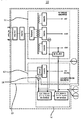
- FIG. 1 is a block diagram illustrating an embodiment of the invention.
- FIG. 2 is a flow chart illustrating an operating method of the present invention.
- the computer power supply 10 having a fan control circuit for cooling the standby power unit in a state where the computer of the present invention is turned off is installed inside the computer main body as shown in FIG. 1 and operates the computer through electricity transmitted from the outside. It is formed of a power source 13 for generating a main power source 11 and a standby power source 12 to provide power to each component included in the computer main body.
- the main power source 11 is a general power source used to operate a computer (not shown) and the standby power source 12 is electricity flowing inside the main body of the computer even when the computer is not turned on. The detailed description is omitted.
- the standby power supply 12 is configured to use a voltage relatively lower than that of the main power supply 11.
- the computer main body includes a memory (not shown in the drawing), a main board (not shown in the drawing), a central processing unit (not shown in the drawing), and a fan (not shown) which are generally installed in the computer so as to operate the computer.
- a memory not shown in the drawing
- main board not shown in the drawing
- central processing unit not shown in the drawing
- fan not shown
- buttons (not shown), liquid crystals (not shown), and the like, which allow a user to set temperature and current values of computer components, are obvious and will not be described in detail.
- a cooling control circuit 14 is formed to include a cooling control circuit 14 that operates the fan through the standby power supply 12 of the power supply unit 13 to lower the temperature or current value of the components included in the computer main body.
- the cooling control circuit 14 is formed by additionally connecting a detection sensor 15 for detecting the amount or temperature of the current flowing into the cooling control circuit 14 connected to the standby power source 12 of the power supply unit 13. You may.
- the sensor 15 is a matter that can be used to select any sensor currently used in general, such as a temperature sensor, current sensor, resistance sensor according to the user's purpose will not be described in detail.
- the present invention will be described by setting the power supply unit 13, the cooling control circuit 14 and the detection sensor 15 belonging to a computer component.
- the sensing sensor 15 connected to the cooling control circuit 14 continuously detects a temperature or a current amount of a component of the computer main body or the cooling control circuit 14.
- the sensing sensor 15 connected to the cooling control circuit 14 is maintained in a state where the main power 11 of the power supply unit 13 is disconnected and the computer is turned off, and the standby power supply 12 flows in the cooling control circuit.
- detecting computer parts including (14).
- the computer is operated by the main power source 11, and according to the user's purpose, the main sensor 11 is cut off and the sensor 15 continues to perform the sensing operation as described above even after the computer is turned off. .
- the sensing sensor 15 detects the temperature or current value of the computer component including the cooling control circuit 14 and compares it with the temperature and current value initially set by the user, and then measures it in the sensing sensor 15. When the measured value is lower than the set value by the user, the sensor 15 continuously detects the temperature and current of the computer component while the standby power 12 maintains the current state without applying power to the fan. (S20)
- the cooling control circuit 14 operates the standby power supply 12 of the power supply unit 13 to operate the standby power supply 12. It is applied to a fan to drive the fan.
- the temperature of the components included in the computer main body is lowered by the driving of the fan, or the value of the current is lowered below the value set by the user (S30).
- the sensor 15 may re-measure the temperature and current values of the computer component to change the temperature or current value of the computer component.
- the operation of the fan operated by the standby power supply 12 is stopped while the standby power supply 12 is stopped.
- the sensor 15 continuously detects the temperature and current of the computer component.
- the fan continuously operates the fan while maintaining the standby power 12 currently operating, and the value measured by the sensor 15 is measured. Keep it lower than the setting value set by this user.
- the cooling control circuit 13 manages the computer component while controlling the driving of the fan through the standby power source 12.
- the fan is driven through the standby power supply 12 to dissipate heat generated from the components to the outside. In other words, it works to minimize the reduced durability of the component.
- the use of standby power (12) operates the computer parts. Temperature or current can be increased, and at this time, the detection sensor 15 continuously detects the temperature and current values of the cooling control circuit 14 and the components, and the temperature or current is higher than the value set by the user. When is raised, it operates as described above to prevent the increase in temperature or current.
- the fan can be driven only by the standby power supply 12 having a lower voltage than the main power supply 11, thereby reducing the use of electricity according to the use of voltage, thereby reducing the power cost.
- the fan can be driven even by the standby power source 12 having a relatively low voltage, thereby reducing the power cost according to electric saving.
Landscapes
- Engineering & Computer Science (AREA)
- Theoretical Computer Science (AREA)
- General Engineering & Computer Science (AREA)
- Physics & Mathematics (AREA)
- General Physics & Mathematics (AREA)
- Human Computer Interaction (AREA)
- Computer Hardware Design (AREA)
- Computing Systems (AREA)
- Power Engineering (AREA)
- Cooling Or The Like Of Electrical Apparatus (AREA)
- Power Sources (AREA)
- Control Of Temperature (AREA)
Abstract
Description
Claims (2)
- 주전원(11)과 대기전원(12)을 생성하면서 컴퓨터 본체에 포함된 각각의 부품으로 전원을 제공하는 전원부(13), 상기 전원부(13)의 대기전원(12)에 연결되며 컴퓨터 본체에 포함된 각각의 부품의 온도 또는 전류를 측정하여 사용자가 설정한 수치와 비교분석하여, 사용자가 설정한 수치 이상일 경우에만 전원부(13)의 대기전원(12)을 통해 팬을 구동시켜 컴퓨터 본체에 포함된 부품의 온도 또는 전류의 수치를 낮추도록 작동하는 냉각제어회로(14)와, 상기 전원부(13)에 연결되는 냉각제어회로(14)에는 전원부(13)의 주전원(11)이 끊겨 컴퓨터가 꺼진 상태에서도 지속적으로 컴퓨터의 부품의 온도 및 전류 값을 감지하는 감지센서(15)가 연결되어 형성되는 것에 특징이 있는 컴퓨터가 꺼진 상태에서 대기전원부 냉각시키는 팬 제어회로를 갖춘 컴퓨터용 전원공급장치.
- 컴퓨터 본체에 설치되어 주전원과 대기전원으로 구성된 전원부와 상기 전원부에 연결되어 컴퓨터 부품의 온도나 전류를 측정하여 일정한 수치 이하로 하강시키되 온도 또는 전류를 측정하는 감지센서가 연결되는 냉각제어회로가 포함된 컴퓨터가 꺼진 상태에서 대기전원부 냉각시키는 팬 제어회로를 갖춘 컴퓨터용 전원공급장치의 운영방법에 있어서,상기 냉각제어회로에 연결된 감지센서가 전원부의 주전원이 끊겨 컴퓨터가 꺼진 상태에서도 지속적으로 컴퓨터의 부품의 온도 및 전류 값을 감지하는 감지단계(S10);상기 감지단계(S10)에서 감지된 컴퓨터 부품의 온도나 전류 값과 사용자가 설정한 설정치 값을 비교하여, 감지센서에 의해 측정된 값이 설정치 값보다 낮을 경우 지속적으로 컴퓨터 부품의 온도 또는 전류를 감지하는 비교단계(S20);상기 비교단계(S20)에서 감지센서에 의해 측정된 값이 설정치 값보다 높을 경우 전원부의 대기전원을 통해 팬을 구동시켜 팬을 통해 컴퓨터 부품의 온도나 전류를 낮추도록 하는 구동단계(S30);상기 구동단계(S30)에서 대기전원을 통해 팬이 구동되면 컴퓨터 부품의 현재의 온도나 전류 값을 상기 냉각제어회로에 연결된 감지센서가 다시 측정하는 재감지단계(S40);상기 재감지단계(S40)에서 측정된 값이 설정치 값보다 낮을 경우 대기전원을 차단하면서 팬의 구동을 멈추고 상기 감지센서가 지속적으로 컴퓨터 부품의 온도나 전류를 감지하며, 감지센서에서 측정된 값이 설정치 값보다 높을 경우 대기전원이 팬으로 전원을 지속적으로 공급하여 팬을 구동시키면서 컴퓨터 부품의 온도나 전류가 낮추도록 하는 연속감지단계(S50);로 이루어진 것에 특징이 있는 컴퓨터가 꺼진 상태에서 대기전원부 냉각시키는 팬 제어회로를 갖춘 컴퓨터용 전원공급장치의 운영방법.
Priority Applications (5)
| Application Number | Priority Date | Filing Date | Title |
|---|---|---|---|
| CN201580072723.5A CN107209537A (zh) | 2015-01-09 | 2015-11-16 | 具有在计算机关闭状态下冷却备用电源部的风扇控制电路的计算机用电源供给装置及运行方法 |
| JP2017554221A JP6460499B2 (ja) | 2015-01-09 | 2015-11-16 | コンピュータの電源が切れた状態で待機電源部を冷却するファン制御回路を備えたコンピュータ用電源供給装置及びその制御方法 |
| EP15877173.3A EP3244284A4 (en) | 2015-01-09 | 2015-11-16 | Computer power supply device having fan control circuit for cooling standby power source unit in state in which computer is turned off, and operating method |
| RU2017128216A RU2654198C1 (ru) | 2015-01-09 | 2015-11-16 | Устройство компьютерного источника питания, имеющее схему управления вентилятором для охлаждения блока источника питания в режиме ожидания в состоянии, в котором компьютер выключен, и способ функционирования |
| US15/540,370 US20170351306A1 (en) | 2015-01-09 | 2015-11-16 | Computer power supply device having fan control circuit for cooling standby power source unit in state in which computer is turned off, and operating method |
Applications Claiming Priority (2)
| Application Number | Priority Date | Filing Date | Title |
|---|---|---|---|
| KR10-2015-0003422 | 2015-01-09 | ||
| KR1020150003422A KR101564428B1 (ko) | 2015-01-09 | 2015-01-09 | 컴퓨터가 꺼진 상태에서 대기전원부 냉각시키는 팬 제어회로를 갖춘 컴퓨터용 전원공급장치 및 운영방법 |
Publications (1)
| Publication Number | Publication Date |
|---|---|
| WO2016111453A1 true WO2016111453A1 (ko) | 2016-07-14 |
Family
ID=54431109
Family Applications (1)
| Application Number | Title | Priority Date | Filing Date |
|---|---|---|---|
| PCT/KR2015/012257 Ceased WO2016111453A1 (ko) | 2015-01-09 | 2015-11-16 | 컴퓨터가 꺼진 상태에서 대기전원부 냉각시키는 팬 제어회로를 갖춘 컴퓨터용 전원공급장치 및 운영방법 |
Country Status (7)
| Country | Link |
|---|---|
| US (1) | US20170351306A1 (ko) |
| EP (1) | EP3244284A4 (ko) |
| JP (1) | JP6460499B2 (ko) |
| KR (1) | KR101564428B1 (ko) |
| CN (1) | CN107209537A (ko) |
| RU (1) | RU2654198C1 (ko) |
| WO (1) | WO2016111453A1 (ko) |
Cited By (2)
| Publication number | Priority date | Publication date | Assignee | Title |
|---|---|---|---|---|
| CN106455453A (zh) * | 2016-11-29 | 2017-02-22 | 深圳天珑无线科技有限公司 | 移动终端的散热方法及移动终端 |
| CN108990364A (zh) * | 2017-06-05 | 2018-12-11 | 北京小米移动软件有限公司 | 电子设备 |
Families Citing this family (5)
| Publication number | Priority date | Publication date | Assignee | Title |
|---|---|---|---|---|
| KR102471466B1 (ko) * | 2015-10-14 | 2022-11-29 | 삼성전자주식회사 | 외장형 통신장치, 디스플레이 장치, 디스플레이 시스템, 및 그 제어방법 |
| KR101633297B1 (ko) * | 2016-01-12 | 2016-06-24 | 주식회사 한미마이크로닉스 | 전자 디바이스의 대기전력 감소를 위한 전원공급장치 및 방법 |
| CN106020391B (zh) * | 2016-05-12 | 2019-09-20 | 福建捷联电子有限公司 | 一种微小型电脑风扇控制方法 |
| US10939593B2 (en) | 2019-04-29 | 2021-03-02 | The Esab Group Inc. | Power supply fan management |
| CN112963372B (zh) * | 2021-03-11 | 2022-11-18 | 英业达科技有限公司 | 风扇控制系统及其方法 |
Citations (5)
| Publication number | Priority date | Publication date | Assignee | Title |
|---|---|---|---|---|
| JP2000029574A (ja) * | 1998-07-15 | 2000-01-28 | Nec Corp | コンピュータ用冷却システム |
| KR20030008060A (ko) * | 2001-07-16 | 2003-01-24 | 삼성전자 주식회사 | 휴대용 컴퓨터 및 휴대용 컴퓨터의 냉각팬 제어방법 |
| KR100371461B1 (ko) * | 1998-07-15 | 2003-04-21 | 엘지전자 주식회사 | 컴퓨터의냉각장치 |
| KR200326981Y1 (ko) * | 2003-06-03 | 2003-09-19 | 에너맥스 테크놀로지 코포레이션 | 전원이 차단된 후 시스템을 냉각시키는 냉각팬이 구비된전원공급장치 |
| KR20040100541A (ko) * | 2003-05-23 | 2004-12-02 | 삼성전자주식회사 | 컴퓨터 시스템 및 그 냉각팬 제어방법 |
Family Cites Families (12)
| Publication number | Priority date | Publication date | Assignee | Title |
|---|---|---|---|---|
| US7167993B1 (en) * | 1994-06-20 | 2007-01-23 | Thomas C Douglass | Thermal and power management for computer systems |
| JPH0962370A (ja) * | 1995-08-29 | 1997-03-07 | Nec Gumma Ltd | 電子機器の冷却装置 |
| CN2610394Y (zh) * | 2003-02-28 | 2004-04-07 | 上海北大方正科技电脑系统有限公司 | 计算机电源 |
| TW572579U (en) * | 2003-05-12 | 2004-01-11 | Enermax Technology Corp | Power supply still capable of dissipating heat after powering off a computer |
| CN2694353Y (zh) * | 2003-06-20 | 2005-04-20 | 保锐科技股份有限公司 | 电脑关机后仍具散热效果的电源供应器 |
| US7605933B2 (en) * | 2006-07-13 | 2009-10-20 | Ricoh Company, Ltd. | Approach for securely processing an electronic document |
| RU2319327C1 (ru) * | 2006-09-12 | 2008-03-10 | Федеральное государственное учреждение Российский научный центр "Курчатовский институт" | Устройство для охлаждения электронных блоков |
| US7460366B2 (en) * | 2007-01-09 | 2008-12-02 | Zippy Technology Corp. | Heat disspating apparatus with stationary power supply |
| KR101074785B1 (ko) * | 2010-05-31 | 2011-10-19 | 삼성에스디아이 주식회사 | 배터리 관리 시스템 및 이의 제어 방법, 및 배터리 관리 시스템을 포함한 에너지 저장 시스템 |
| EP2650751A1 (en) * | 2010-12-09 | 2013-10-16 | BlackBerry Limited | Method and apparatus for handheld device airflow |
| RU116253U1 (ru) * | 2012-01-31 | 2012-05-20 | Андрей Юрьевич Шатин | Система охлаждения суперкомпьютера |
| CN202579254U (zh) * | 2012-03-30 | 2012-12-05 | 中国长城计算机深圳股份有限公司 | 一种计算机及散热风扇驱动延时控制电路 |
-
2015
- 2015-01-09 KR KR1020150003422A patent/KR101564428B1/ko active Active
- 2015-11-16 CN CN201580072723.5A patent/CN107209537A/zh active Pending
- 2015-11-16 JP JP2017554221A patent/JP6460499B2/ja not_active Expired - Fee Related
- 2015-11-16 EP EP15877173.3A patent/EP3244284A4/en not_active Withdrawn
- 2015-11-16 US US15/540,370 patent/US20170351306A1/en not_active Abandoned
- 2015-11-16 RU RU2017128216A patent/RU2654198C1/ru not_active IP Right Cessation
- 2015-11-16 WO PCT/KR2015/012257 patent/WO2016111453A1/ko not_active Ceased
Patent Citations (5)
| Publication number | Priority date | Publication date | Assignee | Title |
|---|---|---|---|---|
| JP2000029574A (ja) * | 1998-07-15 | 2000-01-28 | Nec Corp | コンピュータ用冷却システム |
| KR100371461B1 (ko) * | 1998-07-15 | 2003-04-21 | 엘지전자 주식회사 | 컴퓨터의냉각장치 |
| KR20030008060A (ko) * | 2001-07-16 | 2003-01-24 | 삼성전자 주식회사 | 휴대용 컴퓨터 및 휴대용 컴퓨터의 냉각팬 제어방법 |
| KR20040100541A (ko) * | 2003-05-23 | 2004-12-02 | 삼성전자주식회사 | 컴퓨터 시스템 및 그 냉각팬 제어방법 |
| KR200326981Y1 (ko) * | 2003-06-03 | 2003-09-19 | 에너맥스 테크놀로지 코포레이션 | 전원이 차단된 후 시스템을 냉각시키는 냉각팬이 구비된전원공급장치 |
Non-Patent Citations (1)
| Title |
|---|
| See also references of EP3244284A4 * |
Cited By (2)
| Publication number | Priority date | Publication date | Assignee | Title |
|---|---|---|---|---|
| CN106455453A (zh) * | 2016-11-29 | 2017-02-22 | 深圳天珑无线科技有限公司 | 移动终端的散热方法及移动终端 |
| CN108990364A (zh) * | 2017-06-05 | 2018-12-11 | 北京小米移动软件有限公司 | 电子设备 |
Also Published As
| Publication number | Publication date |
|---|---|
| RU2654198C1 (ru) | 2018-05-16 |
| US20170351306A1 (en) | 2017-12-07 |
| JP2018503210A (ja) | 2018-02-01 |
| JP6460499B2 (ja) | 2019-01-30 |
| EP3244284A1 (en) | 2017-11-15 |
| KR101564428B1 (ko) | 2015-10-30 |
| EP3244284A4 (en) | 2018-08-08 |
| CN107209537A (zh) | 2017-09-26 |
Similar Documents
| Publication | Publication Date | Title |
|---|---|---|
| WO2016111453A1 (ko) | 컴퓨터가 꺼진 상태에서 대기전원부 냉각시키는 팬 제어회로를 갖춘 컴퓨터용 전원공급장치 및 운영방법 | |
| TWI643074B (zh) | 一種電源傳輸控制模組 | |
| CN101667741B (zh) | 充电电路、充电电流传输方法及电池充电系统 | |
| TWI461891B (zh) | 電源管理電路及其方法 | |
| US20100060233A1 (en) | Charger with USB detection | |
| US20130275779A1 (en) | Terminal device and power supply method for terminal device | |
| CN109378877B (zh) | 充电电路、充电处理方法、电子设备及存储介质 | |
| WO2021262414A1 (en) | Hardware architecture for usb-c port power | |
| CN105098890B (zh) | 充电数据线及充电器 | |
| TW201432432A (zh) | 電源管理電路與方法以及電腦系統 | |
| WO2014003419A1 (ko) | 전원 어댑터를 이용하는 전자제품의 대기전력 차단 장치 | |
| US20160049812A1 (en) | Battery expansion system having a single route for charging and discharging and battery charging and discharging control method thereof | |
| CN202076771U (zh) | 一种usb otg电路及应用其的便携式电子设备 | |
| US10019269B2 (en) | Standalone automation device and a machine | |
| WO2017122852A9 (ko) | 전자 디바이스의 대기전력 감소를 위한 전원공급장치 및 방법 | |
| US20120112560A1 (en) | Thermal control power device | |
| CN103677914B (zh) | 一种嵌入式系统简便切换介质引导启动装置及方法 | |
| CN110365082B (zh) | 电源管理电路、电子设备及电源管理方法 | |
| KR20080002868A (ko) | 전력 어댑터, 전력 구동 디바이스 및 컴퓨터 시스템에서전력 관리를 디스에이블링하는 방법 | |
| JP2026034679A (ja) | 携帯端末、充電制御方法、及び、充電制御プログラム | |
| CN109286220B (zh) | 充电电路、充电处理方法、电子设备及存储介质 | |
| KR100736079B1 (ko) | 휴대용 기기의 전원 관리 장치 및 방법 | |
| CN204858641U (zh) | 充电数据线及充电器 | |
| CN106356967A (zh) | 一种适配器以及配置有所述适配器的电子设备 | |
| CN109782205A (zh) | 智能电池传感器测试装置 |
Legal Events
| Date | Code | Title | Description |
|---|---|---|---|
| 121 | Ep: the epo has been informed by wipo that ep was designated in this application |
Ref document number: 15877173 Country of ref document: EP Kind code of ref document: A1 |
|
| WWE | Wipo information: entry into national phase |
Ref document number: 15540370 Country of ref document: US |
|
| REEP | Request for entry into the european phase |
Ref document number: 2015877173 Country of ref document: EP |
|
| ENP | Entry into the national phase |
Ref document number: 2017554221 Country of ref document: JP Kind code of ref document: A |
|
| NENP | Non-entry into the national phase |
Ref country code: DE |
|
| ENP | Entry into the national phase |
Ref document number: 2017128216 Country of ref document: RU Kind code of ref document: A |