WO2016113798A1 - 蓄電モジュール、蓄電システム、電子機器、電動車両および電力システム - Google Patents
蓄電モジュール、蓄電システム、電子機器、電動車両および電力システム Download PDFInfo
- Publication number
- WO2016113798A1 WO2016113798A1 PCT/JP2015/006182 JP2015006182W WO2016113798A1 WO 2016113798 A1 WO2016113798 A1 WO 2016113798A1 JP 2015006182 W JP2015006182 W JP 2015006182W WO 2016113798 A1 WO2016113798 A1 WO 2016113798A1
- Authority
- WO
- WIPO (PCT)
- Prior art keywords
- battery
- storage module
- power storage
- power
- conductive material
- Prior art date
- Legal status (The legal status is an assumption and is not a legal conclusion. Google has not performed a legal analysis and makes no representation as to the accuracy of the status listed.)
- Ceased
Links
Images


Classifications
-
- H—ELECTRICITY
- H01—ELECTRIC ELEMENTS
- H01M—PROCESSES OR MEANS, e.g. BATTERIES, FOR THE DIRECT CONVERSION OF CHEMICAL ENERGY INTO ELECTRICAL ENERGY
- H01M10/00—Secondary cells; Manufacture thereof
- H01M10/60—Heating or cooling; Temperature control
- H01M10/63—Control systems
- H01M10/637—Control systems characterised by the use of reversible temperature-sensitive devices, e.g. NTC, PTC or bimetal devices; characterised by control of the internal current flowing through the cells, e.g. by switching
-
- H—ELECTRICITY
- H01—ELECTRIC ELEMENTS
- H01M—PROCESSES OR MEANS, e.g. BATTERIES, FOR THE DIRECT CONVERSION OF CHEMICAL ENERGY INTO ELECTRICAL ENERGY
- H01M10/00—Secondary cells; Manufacture thereof
- H01M10/60—Heating or cooling; Temperature control
- H01M10/62—Heating or cooling; Temperature control specially adapted for specific applications
- H01M10/627—Stationary installations, e.g. power plant buffering or backup power supplies
-
- H—ELECTRICITY
- H01—ELECTRIC ELEMENTS
- H01M—PROCESSES OR MEANS, e.g. BATTERIES, FOR THE DIRECT CONVERSION OF CHEMICAL ENERGY INTO ELECTRICAL ENERGY
- H01M10/00—Secondary cells; Manufacture thereof
- H01M10/60—Heating or cooling; Temperature control
- H01M10/64—Heating or cooling; Temperature control characterised by the shape of the cells
- H01M10/643—Cylindrical cells
-
- H—ELECTRICITY
- H01—ELECTRIC ELEMENTS
- H01M—PROCESSES OR MEANS, e.g. BATTERIES, FOR THE DIRECT CONVERSION OF CHEMICAL ENERGY INTO ELECTRICAL ENERGY
- H01M10/00—Secondary cells; Manufacture thereof
- H01M10/60—Heating or cooling; Temperature control
- H01M10/65—Means for temperature control structurally associated with the cells
- H01M10/651—Means for temperature control structurally associated with the cells characterised by parameters specified by a numeric value or mathematical formula, e.g. ratios, sizes or concentrations
- H01M10/652—Means for temperature control structurally associated with the cells characterised by parameters specified by a numeric value or mathematical formula, e.g. ratios, sizes or concentrations characterised by gradients
-
- H—ELECTRICITY
- H01—ELECTRIC ELEMENTS
- H01M—PROCESSES OR MEANS, e.g. BATTERIES, FOR THE DIRECT CONVERSION OF CHEMICAL ENERGY INTO ELECTRICAL ENERGY
- H01M10/00—Secondary cells; Manufacture thereof
- H01M10/60—Heating or cooling; Temperature control
- H01M10/65—Means for temperature control structurally associated with the cells
- H01M10/653—Means for temperature control structurally associated with the cells characterised by electrically insulating or thermally conductive materials
-
- H—ELECTRICITY
- H01—ELECTRIC ELEMENTS
- H01M—PROCESSES OR MEANS, e.g. BATTERIES, FOR THE DIRECT CONVERSION OF CHEMICAL ENERGY INTO ELECTRICAL ENERGY
- H01M10/00—Secondary cells; Manufacture thereof
- H01M10/60—Heating or cooling; Temperature control
- H01M10/65—Means for temperature control structurally associated with the cells
- H01M10/655—Solid structures for heat exchange or heat conduction
- H01M10/6553—Terminals or leads
-
- H—ELECTRICITY
- H01—ELECTRIC ELEMENTS
- H01M—PROCESSES OR MEANS, e.g. BATTERIES, FOR THE DIRECT CONVERSION OF CHEMICAL ENERGY INTO ELECTRICAL ENERGY
- H01M10/00—Secondary cells; Manufacture thereof
- H01M10/60—Heating or cooling; Temperature control
- H01M10/65—Means for temperature control structurally associated with the cells
- H01M10/655—Solid structures for heat exchange or heat conduction
- H01M10/6554—Rods or plates
-
- H—ELECTRICITY
- H01—ELECTRIC ELEMENTS
- H01M—PROCESSES OR MEANS, e.g. BATTERIES, FOR THE DIRECT CONVERSION OF CHEMICAL ENERGY INTO ELECTRICAL ENERGY
- H01M10/00—Secondary cells; Manufacture thereof
- H01M10/60—Heating or cooling; Temperature control
- H01M10/65—Means for temperature control structurally associated with the cells
- H01M10/655—Solid structures for heat exchange or heat conduction
- H01M10/6556—Solid parts with flow channel passages or pipes for heat exchange
-
- H—ELECTRICITY
- H01—ELECTRIC ELEMENTS
- H01M—PROCESSES OR MEANS, e.g. BATTERIES, FOR THE DIRECT CONVERSION OF CHEMICAL ENERGY INTO ELECTRICAL ENERGY
- H01M10/00—Secondary cells; Manufacture thereof
- H01M10/60—Heating or cooling; Temperature control
- H01M10/65—Means for temperature control structurally associated with the cells
- H01M10/656—Means for temperature control structurally associated with the cells characterised by the type of heat-exchange fluid
- H01M10/6561—Gases
- H01M10/6562—Gases with free flow by convection only
-
- H—ELECTRICITY
- H01—ELECTRIC ELEMENTS
- H01M—PROCESSES OR MEANS, e.g. BATTERIES, FOR THE DIRECT CONVERSION OF CHEMICAL ENERGY INTO ELECTRICAL ENERGY
- H01M50/00—Constructional details or processes of manufacture of the non-active parts of electrochemical cells other than fuel cells, e.g. hybrid cells
- H01M50/20—Mountings; Secondary casings or frames; Racks, modules or packs; Suspension devices; Shock absorbers; Transport or carrying devices; Holders
- H01M50/204—Racks, modules or packs for multiple batteries or multiple cells
- H01M50/207—Racks, modules or packs for multiple batteries or multiple cells characterised by their shape
- H01M50/213—Racks, modules or packs for multiple batteries or multiple cells characterised by their shape adapted for cells having curved cross-section, e.g. round or elliptic
-
- H—ELECTRICITY
- H01—ELECTRIC ELEMENTS
- H01M—PROCESSES OR MEANS, e.g. BATTERIES, FOR THE DIRECT CONVERSION OF CHEMICAL ENERGY INTO ELECTRICAL ENERGY
- H01M50/00—Constructional details or processes of manufacture of the non-active parts of electrochemical cells other than fuel cells, e.g. hybrid cells
- H01M50/20—Mountings; Secondary casings or frames; Racks, modules or packs; Suspension devices; Shock absorbers; Transport or carrying devices; Holders
- H01M50/289—Mountings; Secondary casings or frames; Racks, modules or packs; Suspension devices; Shock absorbers; Transport or carrying devices; Holders characterised by spacing elements or positioning means within frames, racks or packs
- H01M50/291—Mountings; Secondary casings or frames; Racks, modules or packs; Suspension devices; Shock absorbers; Transport or carrying devices; Holders characterised by spacing elements or positioning means within frames, racks or packs characterised by their shape
-
- H—ELECTRICITY
- H01—ELECTRIC ELEMENTS
- H01M—PROCESSES OR MEANS, e.g. BATTERIES, FOR THE DIRECT CONVERSION OF CHEMICAL ENERGY INTO ELECTRICAL ENERGY
- H01M10/00—Secondary cells; Manufacture thereof
- H01M10/60—Heating or cooling; Temperature control
- H01M10/61—Types of temperature control
- H01M10/613—Cooling or keeping cold
-
- H—ELECTRICITY
- H01—ELECTRIC ELEMENTS
- H01M—PROCESSES OR MEANS, e.g. BATTERIES, FOR THE DIRECT CONVERSION OF CHEMICAL ENERGY INTO ELECTRICAL ENERGY
- H01M10/00—Secondary cells; Manufacture thereof
- H01M10/60—Heating or cooling; Temperature control
- H01M10/61—Types of temperature control
- H01M10/617—Types of temperature control for achieving uniformity or desired distribution of temperature
-
- H—ELECTRICITY
- H01—ELECTRIC ELEMENTS
- H01M—PROCESSES OR MEANS, e.g. BATTERIES, FOR THE DIRECT CONVERSION OF CHEMICAL ENERGY INTO ELECTRICAL ENERGY
- H01M10/00—Secondary cells; Manufacture thereof
- H01M10/60—Heating or cooling; Temperature control
- H01M10/62—Heating or cooling; Temperature control specially adapted for specific applications
- H01M10/625—Vehicles
-
- Y—GENERAL TAGGING OF NEW TECHNOLOGICAL DEVELOPMENTS; GENERAL TAGGING OF CROSS-SECTIONAL TECHNOLOGIES SPANNING OVER SEVERAL SECTIONS OF THE IPC; TECHNICAL SUBJECTS COVERED BY FORMER USPC CROSS-REFERENCE ART COLLECTIONS [XRACs] AND DIGESTS
- Y02—TECHNOLOGIES OR APPLICATIONS FOR MITIGATION OR ADAPTATION AGAINST CLIMATE CHANGE
- Y02E—REDUCTION OF GREENHOUSE GAS [GHG] EMISSIONS, RELATED TO ENERGY GENERATION, TRANSMISSION OR DISTRIBUTION
- Y02E60/00—Enabling technologies; Technologies with a potential or indirect contribution to GHG emissions mitigation
- Y02E60/10—Energy storage using batteries
Definitions
- This technology relates to a power storage module, a power storage system, an electronic device, an electric vehicle, and a power system.
- the power storage module is formed, for example, by housing one or a plurality of battery blocks that are assembled batteries in an outer case.
- the battery block is formed by connecting a plurality of unit batteries (also referred to as single cells or cells. In the following description, they are simply referred to as battery cells) as an example of a storage element.
- Patent Documents 1 to 5 listed below disclose techniques related to the power storage module.
- An electricity storage module is required to efficiently dissipate the assembled battery.
- an object of the present technology is to provide a power storage module, a power storage system, an electronic device, an electric vehicle, and a power system that can efficiently dissipate the assembled battery.
- the present technology provides a battery block group including a plurality of battery cells, a connection terminal portion bonded to a terminal surface of the plurality of battery cells, and a heat disposed in contact with the connection terminal portion.
- the heat conductive material is composed of at least one of a plurality of scattered members and a member having a gap.
- This is a power storage module in which the heat conductive material is distributed in the center part of the region surrounded by the outermost peripheral edge of the battery block group so as to be denser than the peripheral part surrounding the center part.
- the power storage system, electronic device, electric vehicle, and power system of the present technology include the above-described power storage module.
- FIG. 1 is a perspective view showing an external appearance of the power storage module.
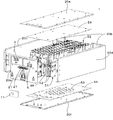
- FIG. 2 is an exploded perspective view showing a configuration example of the power storage module.
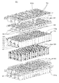
- FIG. 3 is an exploded perspective view showing a configuration example of the battery unit.
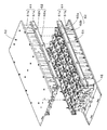
- FIG. 4 is an exploded perspective view showing a configuration example of the top case.
- FIG. 5 is a perspective view showing a state before two battery units are combined.
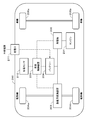
- FIG. 6 is a block diagram showing an outline of the electrical configuration of the power storage module according to the embodiment of the present technology.
- FIG. 7 is a block diagram illustrating an example of the electrical configuration of the power storage module according to the embodiment of the present technology.
- FIG. 8 is a plan view schematically showing the power storage module.
- FIG. 1 is a perspective view showing an external appearance of the power storage module.
- FIG. 2 is an exploded perspective view showing a configuration example of the power storage module.
- FIG. 3 is an exploded perspective view showing a configuration example of the battery unit.
- FIG. 4 is an
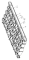
- FIG. 9 is a schematic perspective view showing a configuration of the partition plate and a state before the partition plate and the battery block group are combined.
- FIG. 10 is an exploded perspective view showing the configuration of the front end portion of the power storage module.
- FIG. 11 is a perspective view showing members removed together with the front surface portion.
- FIG. 12 is a perspective view showing a state in which the front portion is removed.
- FIG. 13 is a block diagram showing an outline of the electrical configuration of the power storage module according to the embodiment of the present technology.
- FIG. 14A is a perspective view illustrating a configuration example of a heat conductive material.
- FIG. 14B is a perspective view showing a state in which the heat conductive material is arranged in the connection terminal portion.
- FIG. 14C is a perspective view showing a state in which the heat conductive material is arranged in the connection terminal portion.
- FIG. 15 is a schematic plan view showing an example of the distribution of the heat conductive material.
- FIG. 16A, FIG. 16B, and FIG. 16C are schematic plan views showing examples of the distribution of the heat conductive material.
- FIG. 17 is a schematic plan view showing an example of the distribution of the heat conductive material.
- FIG. 18 is a schematic plan view showing an example of the distribution of the heat conductive material.
- 19A and 19B are schematic plan views showing examples of the distribution of the heat conductive material.
- 20A and 20B are schematic plan views showing examples of the distribution of the heat conductive material.
- FIG. 21 is an exploded perspective view showing another configuration example of the power storage module.
- FIG. 21 is an exploded perspective view showing another configuration example of the power storage module.
- FIG. 22 is a schematic plan view showing an example of the distribution of the heat conductive material.
- FIG. 23 is a schematic plan view showing an example of the distribution of the heat conductive material.
- FIG. 24 is a schematic plan view showing an example of a battery block using square battery cells.
- FIG. 25 is a block diagram for explaining an application example of the power storage module of the present technology.
- FIG. 26 is a block diagram for explaining an application example of the power storage module of the present technology.
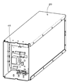
- FIG. 1 is a perspective view showing an external appearance of the power storage module.
- FIG. 2 is an exploded perspective view of the power storage module.
- the power storage module 1 includes an exterior case 20.
- the exterior case 20 has a substantially rectangular parallelepiped shape composed of a front surface portion 20a, a back surface portion 20b facing the front surface portion, and four first to fourth side surface portions 20c to 20f that connect four sides of the front surface portion 20a and the back surface portion 20b.
- This is a housing.
- the first side surface portion 20c and the second side surface portion 20d face each other, and the third side surface portion 20e and the fourth side surface portion f face each other.
- each of the front surface portion 20a, the back surface portion 20b, and the four side surface portions 20c to 20d constituting the exterior case 20 is configured by a plate-like body or a shape-processed plate-like body.
- the plate-like body is, for example, a metal plate such as aluminum, an aluminum alloy, copper, or a copper alloy.
- the front surface portion 20a constituting the housing is covered with a protective cover 21.
- the protective cover 21 is made of an insulating material having an insulating property such as a resin.
- a protective cover 21 made of an insulating material for example, the insulating property between the front surface portion 20a and a connecting member that electrically connects a plurality of power storage modules 1 such as a bus bar is provided.
- the electrical storage module 1 can set surfaces other than the front surface part 20a as a lower surface. That is, the power storage module 1 can have the back surface portion 20b, the first side surface portion 20c, the second side surface portion 20d, the third side surface portion 20e, or the fourth side surface portion 20f as the lower surface.
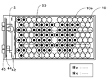
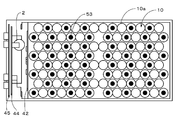
- a battery unit 51 As shown in FIG. 2, in the outer case 20 of the power storage module 1, a battery unit 51, a battery unit 52, a component group including a sub board 42, a main board 46, and the like, a heat conductive material 53, and an insulating material 54. And is housed.
- the battery unit 51 and the insulating material 54 are fixed to the inner surface of the fourth side surface portion 20f of the outer case.
- the insulating material 54 is interposed between the lower surface of the battery unit 51 and the fourth side surface portion 20 f of the exterior case 20, and the heat conducting material 53 is interposed between the insulating material 54 and the lower surface of the battery unit 51.
- the battery unit 52 and the insulating material 54 are fixed to the inner surface of the third side surface portion 20e of the exterior case.
- the insulating material 54 is interposed between the lower surface of the battery unit 52 and the third side surface portion 20 e, and the heat conducting material 53 is interposed between the insulating material 54 and the lower surface of the battery unit 52.
- the battery unit 51 and the battery unit 52 are stacked in two stages in the vertical direction and housed in the outer case 20 with the bottom surface and the top surface of the battery case 61 in a horizontal state with the vertical direction facing the vertical direction.
- the third side surface portion 20e or the fourth side surface portion 20f is placed as the lower surface
- the bottom surface portion and the upper surface portion of the battery case 61 are vertically placed in the horizontal direction, and are stacked in two steps in the horizontal direction. 20.
- FIG. 3 is an exploded perspective view showing a configuration example of the battery unit.
- the battery unit 51 includes a battery case 61 including a top case 61a and a bottom case 61b, a battery block group 10 which is an assembled battery including a plurality of battery cells 10a, and a row of a plurality of battery cells 10a arranged in a row.
- a partition plate 93 inserted between them, a connection terminal portion 91 for electrically connecting a plurality of battery cells 10a, and a positive electrode insulating sheet 92 are accommodated.
- the battery unit 52 has the same configuration as the battery unit 51. Therefore, hereinafter, the configuration of the battery unit 51 will be described in detail, and the detailed description of the configuration of the battery unit 52 will be omitted.
- the battery case 61 includes a top case 61a and a bottom case 61b.
- the battery case 61 is a resin molded product made of a resin having electrical insulation, for example.
- FIG. 4 is a perspective view showing a configuration example of the top case 61a.
- the top case 61a includes an upper surface portion and a wall portion erected around the upper surface portion.
- a plurality of openings 71 through which the connection terminal portions 91 arranged on the terminal surfaces of the plurality of battery cells 10a are exposed are provided on the upper surface portion of the top case 61a.
- a plurality of holes 72 into which protrusions 93a of a partition plate 93 described later are fitted are provided on the upper surface of the top case 61a.
- a fitting portion 62 projects from the upper surface portion of the top case 61a.
- the fitting part 62 includes, for example, a convex fitting part 62a and a concave fitting part 62b.
- a plurality of the protruding fitting portions 62 are provided, whereby a gap can be formed between the battery unit 51 and the battery unit 52 facing each other, and the battery unit 51 and the battery unit 52 are combined. The state where the gap is maintained can be stably maintained.
- the hole for thermistor insertion may be provided in the upper surface part of the top case 61a.
- the bottom case 61b includes a bottom surface portion and a wall portion erected around the bottom surface portion. Although not shown, four hollow structures are provided in a row at the center of the bottom surface portion, and are fitted to the hollow structure 70 of the top case 61a when combined with the top case 61a.
- the hollow structure of the bottom case 61b is, for example, a hollow cylindrical structure having a hollow structure, an upper surface opened, and a hole at the center of the lower surface. The hole is fitted with a protrusion provided on the fourth side surface portion 20f, and is screwed or the like as necessary, so that the battery unit 51 is fixed to the fourth side surface portion 20f.
- a plurality of openings 71 through which the connection terminal portions 91b are exposed are provided on the bottom surface portion of the bottom case 61b, like the top surface portion of the top case 61a.
- a plurality of holes 72 into which protrusions 93a of a partition plate 93 described later are fitted are provided on the bottom surface of the bottom case 61b.
- FIG. 5 is a perspective view showing a state before two battery units are combined. As shown in FIG. 5, when the battery unit 51 and the battery unit 52 are combined, the upper surface portion of the top case 61a of the battery unit 51 and the upper surface portion of the top case 61a of the battery unit 52 are opposed to each other. The fitting portion 62 protruding from the upper surface portion and the fitting portion 62 protruding from the other upper surface portion are fitted.
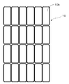
- the battery block group 10 has, for example, a configuration in which battery rows including a plurality of battery cells 10 a arranged in a straight line are juxtaposed in a direction substantially orthogonal to the row direction of the battery rows. ing.
- Each of the battery rows is composed of, for example, 14 batteries.
- the battery block group 10 is an assembled battery in which a plurality of battery cells 10a are electrically connected. A plurality of battery cells 10 a constituting the battery block group 10 are electrically connected by a connection terminal portion 91.
- the battery block group 10 includes, for example, a plurality of battery blocks connected in series, and one battery block includes a plurality (14 in the example of FIG. 3) of battery cells 10a connected in parallel.
- the battery cell 10a is a secondary battery such as a cylindrical lithium ion secondary battery, for example. In addition, the battery cell 10a is not limited to a lithium ion secondary battery.
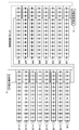
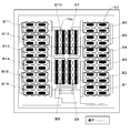
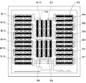
- FIG. 6 shows an outline of the electrical configuration of the power storage module according to the embodiment of the present technology.
- each battery row constitutes battery blocks B1 to B8 in which a plurality of battery cells 10a are connected in parallel. Further, the battery blocks B1 to B8 are connected in series to constitute the battery block group 10.
- the battery block group 10 housed in the battery case 61 of the battery unit 52 has the same configuration.
- each of the battery rows L1 to L8 has a plurality of battery cells 10a connected in parallel.
- the battery blocks B9 to B16 are configured. Further, the battery blocks B9 to B16 are connected in series to constitute the battery block group 10.
- the number of battery cells 10a constituting each battery block is not limited to 14, and the number of battery blocks constituting the battery block group is not limited to the above.
- a plurality of battery rows (battery rows L1 to L8) to which a plurality of battery cells 10a are connected in parallel are juxtaposed in a direction substantially orthogonal to the row direction, and these are connected in series.
- the current path can be rectified in a single direction (for example, a direction substantially orthogonal to the column direction of the battery array) and the total length of the current path can be shortened, and as a result, an increase in resistance can be suppressed.
- the battery row L1 and the battery row L2 are arranged to face each other, the battery row L2 and the battery row L3 are arranged to face each other, the battery row L3 and the battery row L4 are arranged to face each other, and the battery row L4 and the battery row
- the row L5 is arranged to face the battery row
- the battery row L5 and the battery row L6 are arranged to face each other
- the battery row L7 and the battery row L8 are arranged to face each other.
- the plurality of battery cells 10a constituting each battery row are arranged such that the upper surface is a positive electrode terminal surface and the lower surface is a negative electrode terminal surface.
- the plurality of battery cells 10a constituting each battery row are arranged such that the upper surface is a negative electrode terminal surface and the lower surface is a positive electrode terminal surface.
- the plurality of battery cells 10a constituting each battery row are juxtaposed in a straight line and in a close state.
- the 14 battery cells 10a constituting each battery row are arranged in a straight line and in a close contact state.
- the plurality of battery cells 10a constituting each battery row are formed of two sets of the plurality of battery cells 10a arranged in a straight line and in a close state. It arrange
- the space corresponding to this single battery is preferably provided, for example, at a position facing the center of the adjacent and facing battery rows L1, L3, L5, or L7.
- the 14 battery cells 10a constituting each battery row are between two sets of 7 battery cells 10a arranged in a straight line and in a close state, It arrange
- the space substantially corresponding to this single battery is provided, for example, at a position facing the center of the adjacent and facing battery rows L1, L3, L5, or L7.
- a hollow structure (not shown) of the bottom case 61b and a hollow structure 70 of the top case 61a facing the hollow structure are fitted.
- a hole is provided in the bottom surface of the hollow structure 70 of the top case 61a, and the protruding portion of the fourth side surface portion 20f is fitted into this hole, and is screwed as necessary.
- the battery unit 51 is fixed to the portion 20f. By providing the fixing portion with the fourth side surface portion 20f near the center of the battery unit 51, the battery unit 51 may be swollen near the center due to the displacement of the battery cells 10a constituting the battery block group 10. Can be suppressed.
- adjacent battery rows are substantially the same length as the radius of the outer circumference of the battery cell 10a and are stacked in the row direction. It is supposed to be arranged. In a stacked arrangement, other than the row adjacent to one row that falls between the approximate center of the end face of two adjacent battery cells 10a in one row and the two adjacent battery cells 10a in one row. This includes an arrangement in which the approximate center of the battery cells 10a in the row is substantially equilateral triangle.
- the stacked arrangement In the stacked arrangement, a larger number of battery cells 10a can be accommodated in the battery case 61 in a limited space. Therefore, the number of battery cells per area can be increased, and the energy density of the power storage module 1 can be improved. In addition, since heat is easily trapped in the battery block group 10 in the stacked arrangement, it is more effective to dissipate heat efficiently by arranging a heat conductive material 53 described later.
- each of the battery blocks B1 to B16 is connected to a control circuit block (hereinafter referred to as a control block), and charge / discharge is controlled. Charging / discharging is performed via the external positive terminal 4 and the external negative terminal 5.
- a control block a control circuit block
- Charging / discharging is performed via the external positive terminal 4 and the external negative terminal 5.
- a control block is provided in the power storage module 1 in order to monitor the voltage, current, and temperature of the battery cell 10a. Information from the control block is transmitted by communication to an external controller.
- An external controller performs management for charge management, discharge management, deterioration suppression, and the like.
- the control block monitors the voltage of each battery block, converts the detected voltage into a digital signal, and transmits the digital signal to the control box ICNT which is an external controller.
- the temperature of each battery block may be detected, converted into digital data, and transmitted to the control box ICNT.
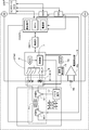
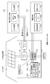
- Fig. 7 shows an example of the control block. As shown in FIG. 7, the voltage at both ends of 16 battery blocks B1 to B16 connected in series and the voltage of each battery block are detected.
- a multiplexer 8 (MUX8) is provided for sequentially outputting the voltage across the battery blocks B1 to B16 and the voltage of each battery block.
- the MUX 8 switches channels according to a predetermined control signal, for example, and selects one analog voltage data from n analog voltage data.
- One analog voltage data selected by the MUX 8 is supplied to an A / D converter (ADC (Analog to Digital Converter) 6).
- ADC Analog to Digital Converter
- the ADC 6 converts the analog voltage data supplied from the MUX 8 into digital voltage data. For example, analog voltage data is converted into digital voltage data of 14 to 18 bits. Digital voltage data from the ADC 6 is supplied to the communication unit COM1.
- the communication unit COM1 is controlled by the control unit 7 and communicates with an external device connected through a communication terminal. For example, communication with another power storage module MO is performed through the communication terminal, and communication with the control box ICNT is performed through the communication terminal. Further, it receives a control signal from the control box ICNT through the communication terminal.
- the communication unit COM1 performs bidirectional communication.
- control unit 7 controls the equalization of the voltages of the battery blocks B1 to B16.
- Such control is referred to as cell balance control.
- cell balance control For example, when one battery block among the plurality of battery blocks B1 to B16 reaches the discharge voltage at the lower limit of use, there is another battery block that still has capacity. When the battery is next charged, the other battery blocks having the remaining capacity quickly reach the charging upper limit voltage and cannot be charged until fully charged. In order to avoid such an imbalance, the remaining battery block is forcibly discharged by turning on a MOSFET (Metal / Oxide / Semiconductor / Field / Effect / Transistor).
- MOSFET Metal / Oxide / Semiconductor / Field / Effect / Transistor
- a control pulse is supplied from the pulse generator 17 to the primary side switch (MOSFET) S1 of the flyback transformer T1 of the module balance control circuit that controls the voltage balance between the power storage module 1 and the plurality of power storage modules MO.
- the pulse generator 17 generates a control pulse according to a control signal from the control unit 7 of the module controller CTN1. For example, the pulse generator 17 outputs a control pulse subjected to pulse width modulation.
- a control pulse for the secondary side switch (MOSFET) S01 of the flyback transformer T1 is supplied from an MCU (MIcro Controller Unit) in the communication unit COM1.
- Control box ICNT determines the balance sequence between the storage modules from the voltage information of each storage module 1 and storage module MO. The presence / absence of charge / discharge of the balance between the storage modules is individually transmitted to the MCU of each storage module.
- the MCU directly supplies a control signal to the secondary side of the flyback transformer, or transmits the control signal to the primary side of the flyback transformer T1 by insulating communication via the insulating unit ISC1.
- the temperature detection unit 15 includes a temperature detection element such as a thermistor.
- Analog temperature data T indicating the temperature of each of the battery blocks B1 to B16 detected by the temperature detector 15 is supplied to the cell temperature multiplexer 16 (MUX16).
- MUX16 cell temperature multiplexer 16
- analog temperature data T1 indicating the temperature of the battery block B1 is supplied to the MUX 16.
- analog temperature data T2 indicating the temperature of the battery block B2 is supplied to the MUX 16.
- analog temperature data T3 to analog temperature data T16 indicating the temperatures of the battery blocks B3 to B16 are supplied to the MUX 16.
- MUX 16 switches channels according to a predetermined control signal, and selects one analog temperature data T from 16 analog temperature data T1 to analog temperature data T16. Then, one analog temperature data T selected by the MUX 16 is supplied to the ADC 6.
- the current detection unit 9 detects the current value flowing through the plurality of battery blocks B1 to B16.
- the current detection unit 9 includes, for example, a current detection resistor 9a and a current detection amplifier 9b.
- the analog current data indicating the voltage value at both ends of the current detection resistor 9a is detected by the current detection resistor 9a.
- the analog current data is always detected regardless of whether it is being charged or discharged.
- the analog current data may be detected at a predetermined cycle.
- Detected analog current data is supplied to the current detection amplifier 9b.
- the supplied analog current data is amplified by the current detection amplifier 9b.
- the amplified analog current data is supplied to the ADC 6.
- the ADC 6 converts the analog current data supplied from the current detection amplifier 9b into digital current data.
- the ADC 6 converts the analog current data into digital current data, and outputs the digital current data.
- the switch (not shown) when the module controller CTN1 detects that an excessive current flows during discharging, it is determined as a discharging overcurrent state, and the switch (not shown) is controlled to be in an open state (a state where current is cut off). To do. On the other hand, when it is detected that an excessive current flows during charging, the switch (not shown) is controlled to an open state (a state where the current is cut off).
- the insulating unit ISC1 has a function of insulating between the communication unit COM1 and the module controller CTN1. That is, the reference potential of the power source of the communication unit COM1 and the reference potential of the power source of the module controller CTN1 are separated and made independent. Furthermore, in an insulated state, the insulating unit ISC1 has a function of supplying a power supply voltage to the module controller CTN1 and a function as a transmission medium for bidirectional communication.
- the CAN standard can be used as a bidirectional communication method performed through the insulating unit ISC1.
- a power transmission method performed through the insulating portion ISC1 an electromagnetic induction method, a magnetic field resonance method, a radio wave reception method, or the like can be used.
- contactless IC card technology is used.
- the non-contact IC card technology performs communication and power transmission between the reader / writer and the card by magnetically coupling the antenna coil of the reader / writer and the antenna coil of the card.
- the communication uses a method of ASK (Amplitude Shift ⁇ Keying) modulation of a carrier wave having a frequency of 13.56 kHz, and a speed of 212 or 424 kbps is performed.
- the insulating part ISC1 has the same specifications as the non-contact IC card method. Further, for example, the insulating portion ISC1 performs communication and power transmission between antennas (coils) formed in different layers of the multilayer printed board.
- connection terminal portion 91 that is a joining member for electrically connecting the plurality of battery cells 10a is provided on the terminal surfaces of the plurality of battery cells 10a.
- the connection terminal portion 91 is, for example, a plate-like body having a planar shape such as a substantially rectangular shape.
- connection terminal portion 91 two connection terminal portions 91a and three connection terminal portions 91b are juxtaposed in a direction substantially orthogonal to the column direction of the battery array.
- the connection terminal portion 91b is provided with a plurality of holes through which the projections 93a of the partition plate 93 are inserted.
- connection terminal portion 91a is electrically joined to the terminal surfaces of the plurality of battery cells 10a constituting one battery row.
- Connection terminal portion 91b is electrically joined to the terminal surfaces of the plurality of battery cells 10a constituting two adjacent battery rows.
- connection terminal portion 91a is electrically joined to the positive terminals of the plurality of battery cells 10a constituting the battery row L1.
- the connection terminal portion 91a is electrically joined to the positive terminals of the plurality of battery cells 10a constituting the battery row L8.
- connection terminal portion 91b is electrically joined to the negative terminals of the plurality of battery cells 10a constituting the battery row L2 and the positive terminals of the plurality of battery cells 10a constituting the battery row L3.
- the connection terminal portion 91b is electrically joined to the negative terminals of the plurality of battery cells 10a constituting the battery row L4 and the positive terminals of the plurality of battery cells 10a constituting the battery row L5.
- Connection terminal portion 91b is electrically joined to the negative terminals of the plurality of battery cells 10a constituting battery row L6 and the positive terminals of the plurality of battery cells 10a constituting battery row L7.
- the joining method includes, for example, electric resistance welding or welding by laser light heating, but is not particularly limited to these methods, and conventionally known welding methods can be appropriately used.
- connection terminal portion 91a or one connection terminal portion 91b by connecting at least one battery row with one connection terminal portion 91a or one connection terminal portion 91b, the resistance value can be reduced and the terminal heat generation can be reduced. Connection between the connection terminal portions can also be performed by simple connection.
- the measurement terminal of the battery cell 10a can also be shared. Since the plurality of battery cells 10a constituting the battery array are joined by one connection terminal portion, the assembling work can be simplified, and the working efficiency at the time of assembling can be improved. In addition, since the number of joints can be reduced, the heat rise of the battery cell 10a at the time of assembly joining can be reduced.
- the heat generated when the battery cell 10a is charged and discharged can be conducted to the connection terminal portion 91a and the connection terminal portion 91b to dissipate heat. Furthermore, heat can be conducted to the exterior case 20 through the heat conductive material 53 in contact with the connection terminal portion 91 to dissipate heat.
- connection terminal on the bottom case side On the inner surface of the bottom surface portion of the bottom case 61b, a plurality of connection terminal portions 91b are juxtaposed as the connection terminal portions 91 in a direction substantially orthogonal to the column direction of the battery array.
- One connection terminal portion 91b is electrically joined to a terminal on the lower surface of the battery cell 10a constituting two adjacent battery rows.
- connection terminal portion 91b is electrically joined to the negative terminals of the plurality of battery cells 10a constituting the battery row L1 and the positive terminals of the plurality of battery cells 10a constituting the battery row L2.
- the connection terminal portion 91b is electrically joined to the negative terminals of the plurality of battery cells 10a constituting the battery row L3 and the positive terminals of the plurality of battery cells 10a constituting the battery row L4.
- Connection terminal portion 91b is electrically joined to the negative terminals of the plurality of battery cells 10a constituting battery row L5 and the positive terminals of the plurality of battery cells 10a constituting battery row L6.
- the connection terminal portion 91b is electrically joined to the negative terminals of the plurality of battery cells 10a constituting the battery row L7 and the positive terminals of the plurality of battery cells 10a constituting the battery row L8.
- a positive electrode insulating sheet 92 is stacked on the positive electrode terminal surface of the battery cell 10 a constituting the battery block group 10. Specifically, the positive electrode insulating sheet 92 is overlaid on the positive electrode terminal surface of the battery cell 10a whose upper surface is the positive electrode terminal surface. A positive electrode insulating sheet 92 is overlaid on the positive electrode terminal surfaces of the plurality of battery cells 10a constituting each battery row.
- the positive electrode insulating sheet 92 is made of an electrically insulating material such as an electrically insulating resin material.
- the positive electrode insulating sheet 92 is provided with a plurality of openings into which a plurality of convex positive terminals are inserted.
- Each positive electrode terminal is inserted into each of the plurality of openings of the positive electrode insulating sheet 92, and each positive electrode terminal is exposed from the opening of the positive electrode insulating sheet 92.
- the positive electrode terminal exposed from the opening of the positive electrode insulating sheet 92 and the connection terminal portion 91a or the connection terminal portion 91b are electrically joined.
- the surface around the positive electrode terminal is covered with the positive electrode insulating sheet 92, whereby the surface around each positive electrode terminal and the connection terminal portion 91a or the connection terminal portion 91b are insulated.
- the positive electrode insulating sheet 92 on the bottom case side is for suppressing a short circuit between the peripheral surface of the convex positive electrode terminal and the connection terminal portion 91b.
- the positive insulating sheet 92 on the battery case side is overlaid on the positive electrode terminal surfaces of the battery cells 10a of the battery row L2, the battery row L4, the battery row L6, and the battery row L8.
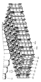
- FIG. 9 is a schematic perspective view showing the configuration of the partition plate and the state before the combination of the partition plate and the battery block group. As shown by the arrows, the partition plate 93 is inserted between the battery rows of the battery block group 10 that face each other and are adjacent to each other.
- the partition plate 93 is, for example, a resin molded product made of an electrically insulating resin.
- the partition plate 93 is detachable from the battery case 61.
- the partition plate 93 includes a plurality of protrusions 93a on the upper surface and the lower surface, and the protrusions 93a are fitted into the holes 72 of the battery case 61 so that the protrusions attached to the battery case 61 are fitted.
- the battery case 61 is removed by removing it from the hole.
- a plurality of protrusions 93 a are provided at predetermined positions on the upper and lower surfaces of the partition plate 93.
- the plurality of protrusions 93a provided on the upper surface are fitted into the plurality of holes 72 for positioning the partition plate provided at predetermined positions of the top case 61a
- the plurality of protrusions 93a provided on the lower surface are It fits into a plurality of holes 72 for positioning the partition plate provided at predetermined positions of the bottom case 61b.
- the partition plate 93 is fixed between the top case 61a and the bottom case 61b.
- a plurality of battery cells 10a can be arranged and fixed at predetermined positions by the fixed partition plate 93.
- a battery block group in which a plurality of battery cells 10a are fixed in an optimum arrangement for high energy density without using a holder case or the like provided with a plurality of individual battery holders corresponding to one battery shape as in the prior art. 10 can be configured.
- the force can be distributed throughout the battery block group 10 by dispersing pressure and stress. Thereby, a deformation
- FIG. 10 is an exploded perspective view showing the configuration of the front end portion of the power storage module.
- FIG. 11 is a perspective view showing members removed together with the front surface portion.
- FIG. 12 is a perspective view showing a state in which the front portion is removed.
- the front surface portion 20a of the housing is covered with a protective cover 21, and a space for housing a component group including a substrate and the like is secured on the inner surface side of the front surface portion 20a.
- a component group including at least the external communication board 45 and the output terminal board 44 shown in FIG. 11 is arranged and fixed.
- this component group includes, for example, an output terminal board 44 provided with the external positive terminal 4 and the external negative terminal 5 which are output terminals, the external communication board 45, the fuse 2, the bus bars 47a1 to 47a3, and the board holding member 49. And members including connectors 3a and 3b.
- the external communication board 45 and the output terminal board 44 are connected to the main board 46 by connectors (not shown).
- the substrate holding member 49 is made of an insulating material such as resin, and has a function of mechanically holding the substrate and also insulating between the substrates and between the substrates and components.
- the two sub-boards 42 are fixed to the battery unit 51 and the battery unit 52, respectively.
- the sub-board is arranged such that one main surface of the sub-board 42 faces and part of the four walls of the battery case 61 are perpendicular to the row direction of the battery row. 42 is arranged and fixed.
- the output terminal board 44, the external communication board 45, and the main board 46 the control blocks including the monitoring and control circuits shown in FIGS. 6 and 7 are mounted.
- a group of components including a plurality of substrates formed of these separate bodies is arranged in a space between the inner surface of the front surface portion 20a and the front wall surfaces of the battery unit 51 and the battery unit 52, and each of them is provided with bus bars 47a1 to 47a3. Since the connection is made by a connecting member such as a plate-like member such as a connector or a connector, the substrates can be easily connected to each other.
- a power storage module 1 is efficient and excellent in assemblability, and can realize high energy by space saving.
- the above-described component group including at least the external communication substrate 45 and the output terminal substrate 44 fixed to the front surface portion 20a is also removed together with the front surface portion 20a.
- the portion including the main board 46 arranged on the back side from the component group is exposed to the outside from the opening of the exterior case 20 from which the front surface portion 20a is removed. Come on. Then, it becomes possible to perform operations such as maintenance of the main board 46 or to quickly take out the main board 46 by inserting a hand into the opening.
- the maintenance and the like of the main board 46 can be performed only by removing the front surface portion 20a and the component group that is removed together with the front surface portion 20a, so that the maintainability can be improved. That is, maintenance and inspection, replacement of parts included in the part group, and the like can be easily performed. Further, it is possible to eliminate the need for taking out complicated wiring and rearranging the wiring.
- the external positive electrode terminal 4 and the external negative electrode terminal 5 provided for charging / discharging the electricity storage module 1 are exposed to the outside through the openings provided in the protective cover 21 and the front surface portion 20a.
- windows 25a-b and 26a-b that are close to each other are formed in the protective cover 21 and the front part 20a on the front part 20a and the protective cover 21 of the power storage module 1. As shown in FIG. 1, the windows 25a to 25b and 26a to 26b are covered with the conductive member 11 when the power storage module 1 is in operation.
- Connectors 3a and 3b are erected on the inside of the windows 25a and 25b formed on the front surface portion 20a. As shown in FIG. 13, the positive terminals of the battery blocks B1 to B16 connected in series are connected to the connector 3a via the fuse 2 that is a current interrupting element. The other connector 3b is provided in the vicinity of the connector 3a. The connector 3b is connected to the external positive terminal 4. Terminals on the negative side of the battery blocks B1 to B16 are connected to the external negative terminal 5.
- a conducting member 11 is provided as a connecting portion to the connectors 3a and 3b so as to be freely inserted and removed in order to prevent erroneous connection.
- the conductive member 11 has a configuration in which the conductive plate is bent so as to have a pair of plate-like protrusions 12 a and 12 b and the base of the conductive plate is attached to one surface of the support plate 13.
- the cover 14 is formed by extending one end of the support plate 13. Further, a knob 15 is formed on the other surface of the support plate 13.
- the support plate 13 having the cover 14 and the knob 15 is, for example, a synthetic resin molded product.
- Each of the connectors 3a and 3b has two spring contact plates arranged opposite to each other, and the plate-like protrusions 12a and 12b of the conducting member 11 are inserted into the opposing gaps between the two spring contact plates through the windows 25a and 25b. It is made to be done. Further, the windows 26a and 26b are closed by the cover 14 integrated with the support plate 13 of the conductive member 11. Since the plate-like protrusions 12a and 12b are sandwiched between the two spring contact plates of the connectors 3a and 3b, the conductive member 11 can be kept inserted into the connectors 3a and 3b.
- the connector 3a and the connector 3b are connected (conducted) by the conducting member 11.
- the connector 3a and the connector 3b are disconnected (non-conductive).
- An electronic component 28 for setting or connection is disposed inside the windows 26a and 26b formed on the front surface portion 20a.
- the electronic component 28 is, for example, a slide switch, a rotary switch, a JTAG connector, or the like.
- an address for the power storage module 1 is set by a rotary switch. That is, a plurality of power storage modules 1 can be connected and used, and when a plurality of power storage modules 1 are connected, an identification address is set for each power storage module.
- An external controller performs control processing based on this address.
- the slide switch is used to increase the address specified by the rotary switch.
- JTAG connector is a standard connector proposed by JTAG (Joint European Test Action). Test data is input / output through the JTAG connector to inspect the MPU (Micro Processing Unit) and IC (Integrated Circuit) inside the case, and the internal MPU firmware is rewritten. In addition, as an electronic component, you may use switching components other than the element mentioned above, a connector, etc.
- the cover 14 closes the windows 25a-b and 26a-b in front of the operation surface of the electronic component. That is, in the connected state, access to the electronic component is blocked.
- a window in front of the operation surface of the setting unit is opened, and the operation surface is operated through the windows 25a-b and 26a-b to set, for example, the address of the power storage module 1. be able to.
- the operation surface can be accessed, and the electronic component setting operation can be performed.
- workability can be improved and safety can be improved as compared to operating the electronic component inside the case.
- the power storage module 1 is provided with a connector 27 that is a communication terminal for communication with an external controller.
- the power storage module 1 is provided with a control block that monitors battery voltage, current, and temperature. Information from the control block is transmitted by communication to an external controller.
- An external controller performs management for charge management, discharge management, deterioration suppression, and the like.
- a serial interface is used for communication with an external controller via the connector 27.
- an SM bus System Management Bus
- an I2C bus can be used as the serial interface.
- the I2C bus is synchronous serial communication in which communication is performed using two signal lines of SCL (serial clock) and bidirectional SDA (serial data).
- the insulating material 54 is provided to ensure the insulation between the battery units 51 and 52 and the outer case 20 or to further improve the insulation.
- the insulating material 55 is made of an electrically insulating material such as a resin material.
- the heat conductive material 53 is attached to the insulating material 54.
- the insulating material 54 is, for example, an insulating sheet that is a sheet-like insulating material, and is interposed between the battery unit 51 and the outer case 20 and between the battery unit 52 and the outer case 20.
- the insulating material 55 may be composed of one insulating sheet, or may have a laminated structure in which two or more insulating sheets are laminated. It is good also as a laminated structure of a resin plate and a metal plate, such as providing one metal plate between two sheet-like resins. In this case, high insulation can be ensured and heat dissipation can be further improved.
- the opening 71 provided in the battery unit 51 where the connection terminal portion 91 is exposed is covered with another insulating material, insulation between the battery unit and the outer case is secured by another member.
- the insulating material 54 may be omitted.
- the heat conductive material 53 is interposed between the connection terminal portion 91 exposed from the opening of the battery case and the inner surface of the outer case 20, and heat of the battery block group 10 is transferred to the outer case via the heat conductive material 53. It is provided to conduct and dissipate heat.
- the plurality of heat conductive materials 53 are arranged in contact with the connection terminal portions 91 as members scattered in a predetermined distribution. By using the interspersed members, it is possible to suppress heat from being accumulated between adjacent battery cells via the heat conductive material 53, and heat can be efficiently dissipated.
- the heat conductive material 53 is made of a material having good heat conductivity, for example.
- the heat conductive material 53 is preferably a material having at least one of good shock absorption characteristics, heat resistance, and insulating properties in addition to heat conductivity.
- heat resistance has heat resistance whose melting
- the heat conducting material 53 a material having excellent heat conductivity such as a plate-like body obtained by performing an insulation coating process on aluminum, copper, magnesium, metal silicon or the like can be used.
- the heat conductive material 53 can be made of, for example, silicon or the like, which is a material having good heat conductivity, good shock absorption characteristics, and heat resistance, or rubber having good heat conductivity and insulation.
- the heat conductive material 53 is, for example, a flexible silicon sheet (FSL250BH) manufactured by Denki Kagaku Kogyo K.K. ) Etc. can be used.
- the heat conductive material 53 may have a structure (for example, a stacked structure) in which a heat conductive material having good heat conductivity and a buffer material having good heat resistance and shock absorption characteristics are combined.
- a structure for example, a stacked structure
- the impact on the battery cell 10a can be mitigated by the cushion effect of the heat conducting material 53 even in a place where there is vibration.
- the impact to the load concentration part and terminal junction part of the battery block group 10 can be reduced, and impact resistance can be improved.
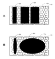
- FIG. 14A is a perspective view illustrating a configuration example of a heat conductive material.
- 14B and 14C are schematic perspective views showing a state in which the heat conductive material is disposed on the connection terminal portion.
- the heat conducting material 53 is, for example, a sheet-like member having a substantially circular planar shape having high heat conductivity.
- the sheet shape means a thin flat shape.
- the planar shape of the heat conducting material 53 is the area of the planar shape of the battery cell 10a (hereinafter, appropriately referred to as the planar shape of the end face of the battery cell 10a) viewed from the normal direction of the surface on which the heat conducting material 53 is disposed. More preferably, it has a small area. This is because the end face of the battery cell 10a is not completely covered with the heat conducting material 53, and a gap for extracting gas from the battery cell 10a is formed at the time of abnormality, and the degassing property can be further improved. In addition, when the area of the heat conductive material 53 is too small, although there exists a tendency for heat dissipation to weaken, gas venting property improves further. Moreover, it is preferable that the heat conductive material 53 is arrange
- the heat conducting material 53 has a planar shape corresponding to the planar shape of the terminal surface of the battery cell 10a joined to the connection terminal portion 91. This is because the heat of the battery cell 10a can be radiated more efficiently.
- the shape corresponding to the planar shape of the terminal surface of the battery cell 10a means the same shape as the planar shape of the terminal surface or a similar shape.
- the heat conductive material 53 has the substantially same planar shape as the positive terminal 10a1 of the battery cell 10a having a substantially circular planar shape, and has a substantially circular planar shape. It has a similar shape to the negative terminal 10a2 of the cell 10a.
- the planar shape of the heat conductive material 53 can take various shapes, and is not limited to the shape corresponding to the planar shape of the terminal surface of the battery cell 10a, but is limited to a substantially circular planar shape. It is not a thing.
- the heat conduction material 53 having the same circle as the + terminal 10a1 surface is disposed so as to face the + terminal 10a1 surface via the connection terminal portion 91, and the connection terminal from the + terminal 10a1. Heat transfer via the part 91 can be performed efficiently.
- the heat conducting material 53 having the same circular shape as the surface of the ⁇ terminal 10a2 is disposed so as to face the central portion of the surface of the ⁇ terminal 10a2 via the connection terminal portion 91. The heat transfer via the connection terminal portion 91 can be performed efficiently.
- the heat conducting material 53 in the example of the cylindrical battery cell 10a, from the viewpoint of further improving the gas release property, the side where the safety valve for venting is not arranged as in the example shown in FIG. 14C.
- the heat conductive material 53 may be disposed on the surface, for example, on the surface of the negative terminal 10a2.
- the temperature in the vicinity of the center of the battery block group 10 where heat is likely to accumulate tends to increase.
- the front end portions of the fuse 2, the sub substrate 42, the output terminal substrate 44, the external communication substrate 45, and the like in the vicinity of the heat generating members that generate heat during the operation of the power storage module 1 are likely to be hotter than other portions. . For this reason, in the battery block group 10, the dispersion
- the heat conducting material 53 is concentrated in the region where the temperature is increased to partially increase the heat dissipation, thereby partially increasing the temperature in the battery block group 10. Can be suppressed. Thereby, the lifetime of the electrical storage module 1 can be improved. In particular, variation in capacity deterioration between the battery cells 10a when using a large current (for example, using 1C or more) can be suppressed, and the charging / discharging operation of the power storage module 1 can be performed stably for a long time. Moreover, since the heat conductive material 53 can be arranged to the minimum necessary, it can contribute to the weight reduction of the electrical storage module 1, and can contribute to the weight suppression of the electrical storage system comprised of many electrical storage modules 1. FIG.
- the heat conductive material 53 of the present technology can secure a ventilation portion inside the power storage module 1 by using a plurality of interspersed members and members having voids, and also secure a gas flow path at the time of abnormality. it can.
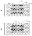
- FIG. 15 is a schematic plan view showing the distribution of the heat conductive material 53 with respect to the end face of the battery block group in a plan view, as viewed from the normal direction of the arrangement surface of the heat conductive material 53.
- a dotted line p in FIG. 15 in the region surrounded by the outermost peripheral edge of the battery block group, the central region of nine regions that are equally divided into three in the vertical direction and equally divided into three in the horizontal direction. It is referred to as a central portion, and a region surrounding the central portion is referred to as a peripheral portion.
- the heat conductive material 53 is arranged so as to have a biased distribution such that the area occupation ratio occupied by the heat conductive material 53 in the center is larger, for example.
- the heat conductive material 53 is arranged so as to be dense in the central portion, and the heat conductive material 53 is arranged so as to be sparser in the peripheral portion than the central portion.
- the determination of dense and sparse is based on the size of the area occupied by the thermal conductive material 53 per unit area (area of the thermal conductive material), with one area out of nine areas divided into approximately six as unit areas.
- the area occupation ratio of the heat conductive material 53 in the central portion is (total area of the heat conductive material 53 in the central portion / 1), and heat conduction in the peripheral portion.
- the area occupancy ratio of the material 53 is (total area of the heat conduction material 53 in the peripheral portion / 8)
- the heat conduction material 53 in the center The area occupancy is higher than the area occupancy of the heat conductive material in the periphery.
- the area occupancy ratio of the heat conductive material 53 in the vicinity of the heat generating member such as the fuse 2, the sub board 42, the output terminal board 44, and the external communication board 45 that generates heat during the operation of the power storage module 1 is further increased. It is preferable to have a distribution that is biased so as to increase. This is because by concentrating the heat conducting material 53 on the heat generating member side, the heat of the battery block group 10 can be radiated more efficiently.
- the heat conductive material 53 is disposed so as to be dense, and in other peripheral portions other than the front end side of the peripheral portion, It arrange
- the area occupancy rate of the heat conductive material 53 on the front end side of the peripheral portion in the vicinity of the heat generating member (total area of the heat conductive material 53 on the front end side of the peripheral portion / 3) is other than the front end side of the peripheral portion.
- Area occupancy ratio of the heat conduction material 53 of the portion total area of the heat conduction material 53 of the other circumferential portion other than the front end side of the circumferential portion / 5).
- the area occupancy occupied by the heat conductive material 53 may have a distribution in the peripheral region. This is because the heat of the battery block group 10 can be dissipated more efficiently by concentrating the heat conductive material 53 at a position where heat is generated at a high level.
- the heat conductive material 53 is arranged densely on the center side, and the heat conductive material is placed on the outer peripheral side from the center portion side. It is arranged so as to be sparse, or arranged so that the heat conducting material 53 is sparse on the center side, and arranged so that the heat conducting material 53 is denser on the outer peripheral side than the center side.
- the heat conductive material 53 on the center side and the heat conductive material 53 on the outer peripheral side are arranged with an equal density.
- the heat conductive material 53 is arranged closer to the center portion side, and the heat conductive material is arranged closer to the outer peripheral side than the center portion side.
- the heat conductive material 53 is arranged so as to be sparse.
- the heat conductive material 53 is arranged so as to be denser in the central portion side, and in the outer peripheral side, the heat conductive material 53 is sparser than the central portion side. It is arranged to be.
- the density of the heat conductive material 53 is determined as follows. For example, each of the six regions in the circumferential portion is divided into two substantially evenly by a straight line (a straight line indicated by a dotted line q in the drawing) that intersects with a straight line toward the center direction. This is carried out by comparing the size of the area occupied by the heat conduction material per unit area (area occupation ratio of the heat conduction material), with one area of two areas divided into two substantially equally.
- the distribution of the heat conducting material 53 may be any distribution as long as the central portion is dense and the peripheral portion is sparser than the central portion, and various distributions can be adopted.
- the distribution of the heat conductive material 53 may be described below.
- other examples (first to third examples) of the distribution of the heat conductive material 53 will be described with reference to FIGS. 16A to 16C.
- 16A to 16C show the heat conducting material 54 attached to the insulating material 54.
- the first example shown in FIG. 16A is a distribution in which the area of the heat conductive material 53 arranged in the two peripheral portions on the center side is made smaller than the distribution of the heat conductive material 53 in the example shown in FIG.
- the number of heat conductive materials 53 arranged in the two peripheral portions on the center side is reduced.
- the heat conducting material 53 is arranged so that the center portion is dense and the peripheral portion is sparser than the center portion. Further, in the first example, similarly to the example shown in FIG. 15, the heat conducting material 53 so that the front end side of the peripheral portion near the heat generating member is denser than other peripheral portions other than the front end side of the peripheral portion. Is arranged.
- the second example shown in FIG. 16B is a distribution in which the area of the heat conductive material 53 arranged in the two peripheral portions on the center side is increased with respect to the distribution of the heat conductive material 53 in the example shown in FIG.
- the number of the heat conductive materials 53 arranged in the two peripheral portions on the center side is larger than the distribution of the heat conductive material 53 in the example shown in FIG.
- the heat conducting material 53 is arranged so that the center portion is dense and the peripheral portion is sparser than the center portion.
- the heat conductive material 53 is arranged so that the front end side of the peripheral portion near the heat generating member and the central side of the peripheral portion are denser than other peripheral portions other than these regions. Yes.
- a third example shown in FIG. 16C is a distribution in which the area of the heat conductive material 53 in the peripheral portion on the front end side is made smaller than the distribution of the heat conductive material 53 in the example shown in FIG.
- the number of heat conductive materials 53 in the peripheral portion on the front end side is smaller than the distribution of the heat conductive material 53 in the example shown in FIG.
- the heat conductive material 53 is arranged so that the center portion is dense and the peripheral portion is sparser than the center portion.
- a heat conductive material 53 (a heat conductive sheet having a substantially circular planar shape (a flexible silicon sheet (FSL250BH) from Denka Chemical Industry Co., Ltd. (DENKA)) is disposed as shown in FIG.
- Sample 2 A power storage module similar to that of Sample 1 was manufactured except that the arrangement of the heat conducting material 53 was changed to the arrangement shown in FIG. Sample 2 is an example in which the heat conductive material 53 is not arranged so that the area occupancy of the heat conductive material 53 is biased in the center with respect to the end face of the battery block group in plan view.
- Example 3 A power storage module similar to that of Sample 1 was manufactured except that the heat conductive material 53 was not disposed.
- Test 1 and Sample 2 were performed, respectively.
- Tests 1 and 2 four measurements were made on one side of the laminate made up of the battery unit 51 and the battery unit 52 on which the heat conductive material 53 is arranged and on the side facing the one side. Points were taken (8 places in total).
- ⁇ Test 1> Under a temperature environment of 45 ° C., a 0.6 C rate continuous charge / discharge test was performed. The maximum temperature among the eight temperature measurement points in the power storage module and the variation (standard deviation) in the maximum temperature of each measurement point were obtained. 1C is a current value at which the theoretical capacity can be discharged or charged in one hour, and 0.6C is a current value at which the theoretical capacity can be discharged or charged in about 1.7 hours.
- the example of the power storage module according to one embodiment is not limited to the one in which the insulating material and the heat conducting material are arranged on both of the two bottom surfaces of the battery units stacked in two stages.
- the example of the power storage module according to one embodiment may have a configuration in which an insulating material and a heat conductive material are arranged only on one side of two bottom surfaces of battery units stacked in two stages.
- the example of the power storage module according to the embodiment is not limited to one in which the distribution of the heat conductive material arranged on both the two bottom surfaces of the battery units stacked in two stages is the same distribution. Absent.
- the arrangement may be such that the distribution of one thermal conductive material on the two bottom surfaces of the battery units stacked in two stages is different from the distribution of the other thermal conductive material.
- two different distributions are selected from one example of the above-described distribution of the heat conducting material 53 and other examples (first to third examples), and one of the selected distributions is selected.
- the heat conducting material 53 is arranged on one side (upper side) of the two bottom surfaces of the battery unit laminated in two stages, and the heat conduction material 53 is arranged on the other side of the two bottom surfaces with the other distribution. You may arrange
- the total arrangement area of the one heat conductive material 53 on the two bottom surfaces of the battery units stacked in two stages and the total arrangement area of the other heat conductive material may be the same or different. Good.
- the total arrangement area of the heat conductive materials 53 can be changed according to a change in a place where heat according to the placement surface tends to be accumulated when the power storage module is placed.
- the planar shape of the heat conductive material is not limited to a substantially circular shape, and may be, for example, an ellipse such as an ellipse or a rectangular shape.
- FIG. 18 shows an example using a rectangular thermal conductive material.
- the rectangular heat conducting material 53 is preferable because the material is improved.
- the example of the power storage module according to the embodiment is not limited to the heat conductive material formed of a plurality of members interspersed, but is mainly disposed at a position corresponding to the terminal surface of the battery cell 10a.
- gap such as a heat conductive material which has a part and the connection part which connects main parts mutually, may be sufficient.
- the main part of this heat conductive material is, for example, one having the same configuration as that of one member of the plurality of scattered members described above.
- the example of the power storage module according to the embodiment is not limited to the case where the heat conductive material 53 has an area smaller than the area of the planar shape of the end face of the battery cell 10a.
- the heat conductive material 53 may be larger than the area of the planar shape of the end face of one or more battery cells 10a.
- a heat conducting material 53 As such a heat conducting material 53, a rectangular shape larger than the total area of the planar shapes of the end faces of the plurality of battery cells 10a shown in FIG. 19A, or a flat surface of the end faces of the plurality of battery cells 10a shown in FIG. 19B.
- An elliptical shape larger than the total area of the shape is exemplified.
- the shape of the heat conducting material 53 is not limited to a rectangular shape, an elliptical shape, or the like, and various shapes can be employed.
- it if it is in the state where the two or more heat conductive materials 53 are spaced apart from each other, they are included in the dot.
- the state in which the three heat conductive materials 53 shown in FIG. 19A are arranged apart from each other and the state in which the two heat conductive materials 53 shown in FIG. 19B are arranged apart from each other are included in the doting.
- These thermal conductive materials 53 are a plurality of scattered members.
- the position of the substrate is not limited and may be arranged at various positions.
- the substrate 50 may be disposed on the side of the battery block group 10.
- the substrate 50 may be disposed above the battery block group 10. Note that the substrate 50 in the figure represents one substrate, but the substrate 50 is at least one of a plurality of substrates (for example, the above-described sub substrate 42, output terminal substrate 44, external communication substrate 45, etc.). May be.
- the heat conductive material 53 it is preferable to change the distribution of the heat conductive material 53 according to the position of the substrate 50.
- the heat conductive material 53 it is preferable to arrange the heat conductive material 53 so that the peripheral portion in the vicinity of the substrate 50 is denser than the other peripheral portions.
- the peripheral portion in the vicinity of the substrate 50 means a peripheral portion at a position facing the substrate 50 in plan view.
- the heat conductive material 53 it is preferable to arrange the heat conductive material 53 so that the area corresponding to the arrangement surface of the substrate 50 is denser than the other areas.
- an external positive terminal 81 and an external negative terminal 82 for charging and discharging the power storage module are provided adjacent to each other on the front surface of the power storage module.
- the exterior case 84 includes an exterior lower case 84a and an exterior upper case 84b.
- the power storage module includes battery blocks B1 to B16 (batteries) including an outer case 84 as a casing, a plurality of battery modules 86 housed in the outer case 84, and a plurality of battery cells 10a included in each battery module 86.
- the battery module 86 is a connection in which a battery block composed of a plurality of battery cells 10a (eight in the example of FIG. 21) connected in parallel is accommodated in a battery holder and joined to a terminal surface of the battery cell 10a.
- the positive electrode metal plate 85a and the negative electrode metal plate 85b which are terminal parts are provided.
- the plurality of heat conductive materials 53 are interposed between the positive electrode metal plate 85a or the negative electrode metal plate 85b, which is the connection terminal portion, and the inner surface of the outer case 84.
- the plurality of heat conductive members 53 arranged on the upper side of the battery block group 10 are connected to the outer case 84b and the connection terminal portion (positive electrode) joined to the terminal surface of the battery cell 10a on the upper side of the battery block group 10. It is interposed between the metal plate 85a or the negative electrode metal plate 85b).
- These heat conductive materials 53 are in contact with both the connection terminal portion (positive metal plate 85a or negative metal plate 85b) and the outer upper case 84b.
- the plurality of heat conductive materials 53 disposed below the battery block group 10 include an exterior lower case 84a, It is interposed between the connection terminal portion (positive metal plate 85a or negative metal plate 85b) joined to the battery cell 10a terminal surface on the lower side of the battery block group 10. These heat conductive materials 53 are in contact with both the connection terminal portion (positive metal plate 85a or negative metal plate 85b) and the outer lower case 84a.
- the exterior case 84 includes an exterior lower case 84a for housing the battery module 86, and an exterior upper case 84b that covers the exterior lower case 84a that houses the plurality of battery modules 86.
- the exterior lower case 84a has a configuration in which a plurality of battery modules 86 can be attached and detached.
- FIG. 22 is a schematic plan view showing the distribution of the heat conductive material 53 with respect to the end surface of the battery block group in a plan view, as viewed from the normal direction of the arrangement surface of the heat conductive material 53.
- the region surrounded by the outermost peripheral edge of the battery block group including the battery blocks B1 to B16 is equally divided into three vertically.
- the central region of the nine regions equally divided into three in the horizontal direction is referred to as the central portion, and the region surrounding the central portion is referred to as the peripheral portion.
- the heat conductive material 53 is arranged so as to have a biased distribution such that the area occupation ratio occupied by the heat conductive material 53 at the center is larger.
- the heat conductive material 53 is arranged so as to be dense in the central portion, and the heat conductive material 53 is arranged so as to be sparser in the peripheral portion than the central portion.
- Such a biased distribution is made, for example, by arranging heat conducting materials 53 of different sizes.
- two types of rectangular heat conductive materials 53 having different sizes are used. Then, one heat conductive material 53 having a small area is arranged at a position corresponding to the four central battery blocks B7 to B10, and the other heat conductive material 53 having a large area is disposed in the four central battery blocks B7.
- the heat conductive material 53 has the above-mentioned uneven distribution.
- the same effects as in the first embodiment are obtained.
- the heat conductive material 53 in the present technology, by disposing the heat conductive material 53 in a concentrated manner in a region where the temperature becomes high, partial heat rise in the battery block group 10 can be suppressed by partially improving heat dissipation. Thereby, the lifetime of an electrical storage module can be improved.
- the heat conductive material 53 since the heat conductive material 53 can be arranged to the minimum necessary, it can contribute to weight reduction of the power storage module, and can contribute to weight reduction of the power storage system including a large number of power storage modules.
- Example 4 As shown in FIG. 22, two types of heat conductive materials 53 having different sizes (a heat conductive sheet having a rectangular planar shape (flexible silicon sheet (FSL250BH) from Denka)) are disposed. A power storage module shown in FIG. 22 was produced. In addition, what reduced 30% of the area from the larger heat conductive material 53 is the smaller heat conductive material 53.
- FSL250BH flexible silicon sheet
- Example 5 As shown in FIG. 23, the power storage shown in FIG. 23 in which a heat conductive material 53 (a heat conductive sheet having a rectangular planar shape (a flexible silicon sheet (FSL250BH) of Denka Chemical Co., Ltd. (DENKA)) is arranged. A module was produced. Note that the heat conductive material 53 shown in FIG. 23 has the same size as the larger heat conductive material 53 of the sample 4. The sample 5 does not have a biased distribution in which the area occupation ratio of the heat conductive material 53 in the center portion is larger than the end face of the battery block group in the plan view. It is.
- a heat conductive material 53 a heat conductive sheet having a rectangular planar shape (a flexible silicon sheet (FSL250BH) of Denka Chemical Co., Ltd. (DENKA)
- Test 3-1 Discharging was performed at an environmental temperature of 23 ° C., a discharge current of 24 A (1 C), and a discharge end voltage of 32.0 V.
- Test 3-2 Discharge was performed at an environmental temperature of 23 ° C., a discharge current of 50 A, and a discharge end voltage of 32.0 V.
- Test 3-3 Discharge was performed at an environmental temperature of 40 ° C., a discharge current of 50 A, and a discharge end voltage of 32.0 V.
- Sample 4 had a smaller ⁇ Tmax ⁇ Tmin [° C.] than Sample 5. That is, in the sample 4, the thermal conduction material 53 is arranged as shown in FIG. In Sample 4, although the total area of the heat conductive material 53 was smaller than that of Sample 5, it was possible to obtain a temperature variation suppression effect superior to that of Sample 5 by efficiently dissipating heat.
- the numerical values, structures, shapes, materials, raw materials, manufacturing processes and the like given in the above-described embodiments and examples are merely examples, and different numerical values, structures, shapes, materials, raw materials, and the like as necessary.
- a manufacturing process or the like may be used.
- the plurality of protrusions and the plurality of holes may be one protrusion and one hole.
- the number of battery units accommodated in the outer case 20 is two has been described.
- the number of battery units accommodated in the outer case 20 is not limited to two.
- the number of battery units accommodated in the outer case may be one, or three or more.
- the power storage module may be housed in the outer case 20 by being stacked in three or more stages in the horizontal direction with the top surface of the top case 61a vertically placed in the horizontal direction.
- the power storage module may be housed in the outer case 20 by being stacked in three or more levels in the horizontal direction with the top surface of the top case 61a being placed in the horizontal direction.
- the bottom surface portion of the bottom case 61b may have the same configuration as the top surface portion of the top case 61a.
- two battery units 51 and 52 that are stacked in two or more levels in the horizontal direction are placed in the outer case 20 so that the top surface of the top case 61a and the bottom surface of the bottom case 61b face in the vertical direction. It is good also as a structure.
- the joining terminal portion may have a configuration in which terminal surfaces of three or more battery rows are joined.
- the battery cell may be applied to other battery structures such as a square or a laminate film type, and the battery block group may be constituted by these battery cells.
- FIG. 24 shows a battery block group using square battery cells.
- the battery block group 10 is composed of, for example, 24 square battery cells 10b connected in two parallel 12 series.
- the electrical storage module of this technique can also take the following structures.
- a battery block group consisting of a plurality of battery cells; A connection terminal portion joined to the terminal surfaces of the plurality of battery cells; A heat conductive material disposed in contact with the connection terminal portion, The heat conducting material is composed of at least one of a plurality of scattered members and a member having a gap, In a plan view as viewed from the normal direction of the arrangement surface of the heat conductive material, the heat conductive material is denser in the center part of the region surrounded by the outermost peripheral edge of the battery block group than the peripheral part surrounding the central part.
- Power storage modules distributed so that [2] In a plan view seen from the normal direction of the arrangement surface of the heat conducting material, the heat conducting material is denser than a part of the peripheral part other than the part of the peripheral part.
- the heat conducting material is composed of a plurality of interspersed members, The power storage module according to any one of [1] to [2], wherein an area of the planar shape of the member is smaller than an area of an end face of the battery cell.
- the heat conducting material is composed of a plurality of interspersed members, The power storage module according to any one of [1] to [7], wherein the shape of the member is the same as or similar to the planar shape of the terminal surface of the battery cell.
- the battery block group, the connection terminal portion and the battery unit including the battery case containing the heat conductive material has a laminate in which two or more stages are laminated, The power storage module according to any one of [1] to [8], wherein the heat conductive material is disposed on one surface side of the laminate and another surface side facing the one surface.
- the battery case includes a structure that is fitted into a space corresponding to approximately one battery cell, [9] The power storage module according to [9], wherein at least a part of the structural body is located at the central portion in a plan view as viewed from the normal direction of the arrangement surface of the heat conductive material. [12] Any one of [1] to [11], wherein the battery block group includes a plurality of battery rows made of the plurality of battery cells arranged in a row in a direction substantially orthogonal to the row direction.
- connection terminal portion is joined to terminal surfaces of a plurality of battery cells constituting at least one of the battery rows, and the longitudinal direction is arranged in parallel to the row direction of the battery rows [12].
- the electricity storage module described.
- [15] [1] A power storage system that includes the power storage module according to any one of [13] and supplies electric power to an electronic device connected to the power storage module.
- [16] [1] An electronic device that is supplied with electric power from the power storage module according to any one of [13].
- a power information transmitting / receiving unit that transmits and receives signals to and from other devices via a network; An electric power system that performs charge / discharge control of the power storage module according to any one of [1] to [13] based on information received by the transmission / reception unit.
- This technology is a power storage system in which the above-described power storage module is charged by a power generation device that generates power from renewable energy.
- the present technology is a power storage system that includes the above-described power storage module and supplies power to an electronic device connected to the power storage module.
- the present technology is an electronic device that receives power supply from the above-described power storage module.
- the present technology provides an electric vehicle that includes a conversion device that receives electric power from the power storage module and converts the power into a driving force of the vehicle, and a control device that performs information processing related to vehicle control based on information about the power storage module. It is.
- the present technology is a power system that includes a power information transmission / reception unit that transmits / receives a signal to / from another device via a network, and performs charge / discharge control of the above-described power storage module based on information received by the transmission / reception unit.
- the present technology is a power system that receives power from the power storage module described above or supplies power to a battery pack of the power storage module from a power generation device or a power network.
- Storage system in a house as an application example An example in which the present technology is applied to a residential power storage system will be described with reference to FIG.
- the power storage system 100 for the house 101 electric power is stored from the centralized power system 102 such as the thermal power generation 102a, the nuclear power generation 102b, and the hydroelectric power generation 102c through the power network 109, the information network 112, the smart meter 107, the power hub 108, and the like. It is supplied to the module 103.
- power is supplied to the power storage module 103 from an independent power source such as the power generation device 104.
- the electric power supplied to the power storage module 103 is stored. Electric power to be used in the house 101 is supplied using the power storage module 103.
- the same power storage system can be used not only for the house 101 but also for buildings.
- the house 101 is provided with a power generation device 104, a power consumption device 105, a power storage module 103, a control device 110 that controls each device, a smart meter 107, and a sensor 111 that acquires various types of information.
- Each device is connected by a power network 109 and an information network 112.
- the power generation device 104 a solar cell, a fuel cell, a windmill, or the like is used, and the generated power is supplied to the power consumption device 105 and / or the power storage module 103.
- the power consuming device 105 includes a refrigerator 105a, an air conditioner 105b that is an air conditioner, a television 105c that is a television receiver, a bus 105d that is a bath, and the like.
- the electric power consumption device 105 includes an electric vehicle 106.
- the electric vehicle 106 is an electric vehicle 106a, a hybrid car 106b, and an electric motorcycle 106c.
- the electric vehicle 106 may be an electric assist bicycle.
- the power storage module 103 includes an assembled battery composed of a secondary battery or the like.
- the assembled battery is constituted by a lithium ion secondary battery.
- the power storage module 1 of the present technology described above can be applied to the power storage module 103.
- One or a plurality of power storage modules 1 can be applied.
- the smart meter 107 has a function of detecting the usage amount of commercial power and transmitting the detected usage amount to an electric power company.
- the power network 109 may be any one or a combination of DC power supply, AC power supply, and non-contact power supply.
- the various sensors 111 are, for example, human sensors, illuminance sensors, object detection sensors, power consumption sensors, vibration sensors, contact sensors, temperature sensors, infrared sensors, and the like. Information acquired by the various sensors 111 is transmitted to the control device 110. Based on the information from the sensor 111, the weather condition, the human condition, etc. can be grasped, and the power consumption device 105 can be automatically controlled to minimize the energy consumption. Furthermore, the control device 110 can transmit information regarding the house 101 to an external power company or the like via the Internet.
- the power hub 108 performs processing such as branching of power lines and DC / AC conversion.
- a communication method of the information network 112 connected to the control device 110 a method using a communication interface such as UART (Universal Asynchronous Receiver Receiver Transmitter), a wireless communication standard such as Bluetooth, ZigBee, Wi-Fi, etc.
- a wireless communication standard such as Bluetooth, ZigBee, Wi-Fi, etc.
- the Bluetooth method is applied to multimedia communication and can perform one-to-many connection communication.
- ZigBee uses the physical layer of IEEE (Institute of Electrical and Electronics Electronics) (802.15.4).
- IEEE802.15.4 is a name of a short-range wireless network standard called PAN (Personal Area Network) or W (Wireless) PAN.
- the control device 110 is connected to an external server 113.
- the server 113 may be managed by any one of the house 101, the power company, and the service provider.
- the information transmitted and received by the server 113 is, for example, information related to power consumption information, life pattern information, power charges, weather information, natural disaster information, and power transactions. These pieces of information may be transmitted / received from a power consuming device (for example, a television receiver) in the home, or may be transmitted / received from a device outside the home (for example, a mobile phone). Such information may be displayed on a device having a display function, for example, a television receiver, a mobile phone, a PDA (Personal Digital Assistant) or the like.
- the control device 110 that controls each unit includes a CPU (Central Processing Unit), a RAM (Random Access Memory), a ROM (Read Only Memory), and the like, and is stored in the power storage module 103 in this example.
- the control device 110 is connected to the power storage module 103, the power generation device 104, the power consumption device 105, the various sensors 111, the server 113 and the information network 112, and has a function of adjusting, for example, the amount of commercial power used and the amount of power generation. is doing. In addition, you may provide the function etc. which carry out an electric power transaction in an electric power market.
- electric power is stored not only in the centralized power system 102 such as the thermal power generation 102a, the nuclear power generation 102b, and the hydroelectric power generation 102c but also in the power storage module 103 from the power generation device 104 (solar power generation, wind power generation). Can do. Therefore, even if the generated power of the power generation device 104 fluctuates, it is possible to perform control such that the amount of power transmitted to the outside is constant or discharge is performed as necessary.
- the power obtained by solar power generation is stored in the power storage module 103, and the nighttime power with a low charge is stored in the power storage module 103 at night, and the power stored by the power storage module 103 is discharged during a high daytime charge. You can also use it.
- control device 110 is stored in the power storage module 103 .
- the control device 110 may be stored in the smart meter 107 or may be configured independently.
- the power storage system 100 may be used for a plurality of homes in an apartment house, or may be used for a plurality of detached houses.
- FIG. 26 schematically shows an example of the configuration of a hybrid vehicle that employs a series hybrid system to which the present technology is applied.
- a series hybrid system is a car that runs on an electric power driving force conversion device using electric power generated by a generator driven by an engine or electric power once stored in a battery.
- the hybrid vehicle 200 includes an engine 201, a generator 202, a power driving force conversion device 203, driving wheels 204a, driving wheels 204b, wheels 205a, wheels 205b, a battery 208, a vehicle control device 209, various sensors 210, and a charging port 211. Is installed.
- the above-described power storage module 1 of the present technology is applied to the battery 208.
- One or more power storage modules 1 are applied.
- Hybrid vehicle 200 travels using electric power / driving force conversion device 203 as a power source.
- An example of the power driving force conversion device 203 is a motor.
- the electric power / driving force converter 203 is operated by the electric power of the battery 208, and the rotational force of the electric power / driving force converter 203 is transmitted to the driving wheels 204a and 204b.
- DC-AC DC-AC
- AC-DC conversion AC-DC conversion
- the power driving force converter 203 can be applied to either an AC motor or a DC motor.
- the various sensors 210 control the engine speed via the vehicle control device 209 and control the opening (throttle opening) of a throttle valve (not shown).
- the various sensors 210 include a speed sensor, an acceleration sensor, an engine speed sensor, and the like.
- the rotational force of the engine 201 is transmitted to the generator 202, and the electric power generated by the generator 202 by the rotational force can be stored in the battery 208.
- the resistance force at the time of deceleration is applied as a rotational force to the power driving force conversion device 203, and the regenerative power generated by the power driving force conversion device 203 by this rotational force is applied to the battery 208. Accumulated.
- the battery 208 is connected to a power source outside the hybrid vehicle, so that it can receive power from the external power source using the charging port 211 as an input port and store the received power.
- an information processing device that performs information processing related to vehicle control based on information related to the secondary battery may be provided.
- an information processing apparatus for example, there is an information processing apparatus that displays a battery remaining amount based on information on the remaining amount of the battery.
- the present technology is also effective for a parallel hybrid vehicle in which the engine and motor outputs are both driving sources, and the system is switched between the three modes of driving with only the engine, driving with the motor, and engine and motor. Applicable. Furthermore, the present technology can be effectively applied to a so-called electric vehicle that travels only by a drive motor without using an engine.
- SYMBOLS 1 Power storage module, 2 ... Fuse, 3a ... Connector, 3b ... Connector, 4 ... External positive electrode terminal, 5 ... External negative electrode terminal, 7 ... Control part, 8 * ..MUX, 9 ... Current detection unit, 9a ... Current detection resistor, 9b ... Current detection amplifier, 10 ... Battery block group, 10a ... Battery cell, 11 ... Conduction member, 12a ... plate-like protrusion, 12b ... plate-like protrusion, 13 ... support plate, 14 ... cover, 15 ... temperature detector, 16 ... MUX, 17 ... pulse generator , 20 ... exterior case, 20a ... front part, 20b ... back part, 20c ...
- Fitting part, 70 Hollow structure, 71 ... Opening 72 ... 91, 91a-91b ... connection terminal, 92 ... positive electrode insulating sheet, 93 ... partition plate, 93a ... projection, 100 ... power storage system, 101. ..Housing 102 ... Centralized power system 102a ... Power generation, 102b ... Nuclear power generation, 102c ... Hydropower generation, 103 ... Power storage module, 104 ... Power generation device, 105 ... Power consumption device, 105a ... Refrigerator, 105b ... Air conditioner 105c ... TV, 105d ... Bus, 106 ... Electric vehicle, 106a ... Electric car, 106b ... Hybrid car, 106c ...
- Electric bike 107 ... Smart meter, 108. ..Power hub 109... Power network 110...
- Control device 111 .. sensor 112 .. information network 113 .. server 200 .. hybrid vehicle 201. ... Generator, 203 ... Power driving force converter, 204a, 204b ... Drive wheels, 205a, 205b ... Wheels, 208 ... Battery Lee, 209 ... vehicle control device, 210 ... sensor, 211 ... charge port, B1 to B16 ... battery block, COM1 ... communication unit, CTN1 ... module controller, ICNT ... Control box, ISC1 ... insulating part, L1 to L8 ... battery row, MO ... storage module
Landscapes
- Chemical & Material Sciences (AREA)
- Chemical Kinetics & Catalysis (AREA)
- Electrochemistry (AREA)
- General Chemical & Material Sciences (AREA)
- Engineering & Computer Science (AREA)
- Manufacturing & Machinery (AREA)
- Automation & Control Theory (AREA)
- Physics & Mathematics (AREA)
- Algebra (AREA)
- General Physics & Mathematics (AREA)
- Mathematical Analysis (AREA)
- Mathematical Optimization (AREA)
- Pure & Applied Mathematics (AREA)
- Battery Mounting, Suspending (AREA)
- Secondary Cells (AREA)
Abstract
Description
1.一の実施の形態(蓄電モジュールの一例)
2.二の実施の形態(蓄電モジュールの他の例)
3.他の実施の形態
4.応用例
なお、以下に説明する実施の形態等は本技術の好適な具体例であり、本技術の内容がこれらの実施の形態等に限定されるものではない。また、本明細書に記載された効果はあくまで例示であって限定されるものではなく、また例示した効果と異なる効果が存在することを否定するものではない。
(蓄電モジュールの構成例)
本技術の一の実施の形態による蓄電モジュールの構成例について、図面を参照しながら説明する。図1は、蓄電モジュールの外観を示す斜視図である。図2は、蓄電モジュールの分解斜視図である。
電池ユニット51および電池ユニット52は、電池ケース61の底面部および上面部が垂直方向に向く横置き状態で、垂直方向に2段積層されて外装ケース20に収容されている。なお、第3側面部20eまたは第4側面部20fを下面として置いた状態では、電池ケース61の底面部および上面部が水平方向に向く縦置き状態で、水平方向に2段積層されて外装ケース20に収容されている。
電池ケース61は、トップケース61aとボトムケース61bとから構成されている。電池ケース61は、例えば、電気絶縁性を有する樹脂からなる樹脂成形品である。
図4はトップケース61aの構成例を示す斜視図である。トップケース61aは、上面部と、この上面部の周囲に立設された壁部とを備える。トップケース61aの上面部には、複数の電池セル10aの端子面上に配置された接続端子部91が露出する複数の開口71が設けられている。
ボトムケース61bは、底面部と、この底面部の周囲に立設された壁部とを備える。なお、図示は省略するが底面部の中央には、4つの中空構造体が、列状に設けられており、トップケース61aと組み合わせた状態で、トップケース61aの中空構造体70と嵌合される。ボトムケース61bの中空構造体は、例えば、中空構造であり、且つ、上面が開口しており、且つ、下面の中心に孔を有する、中空円筒形状の構造体である。なお、孔は、第4側面部20fに設けられた突起部と嵌合し、必要に応じてネジ止め等がなされ、電池ユニット51が第4側面部20fに固定される。図示は省略するが、ボトムケース61bの底面部には、トップケース61aの上面部と同様、接続端子部91bが露出する複数の開口71が設けられている。また、ボトムケース61bの底面部には、後述の仕切り板93の突起部93aが嵌合する複数の孔72が設けられている。
図3に戻り、電池ブロック群10は、例えば、直線状に配置された複数個の電池セル10aからなる電池列が、電池列の列方向に対して略直交する方向に並置された構成とされている。電池列のそれぞれは、例えば、14本の電池で構成されている。
複数の電池セル10aを電気的に接続する接合部材である接続端子部91が、複数の電池セル10aの端子面上に設けられている。接続端子部91は、例えば、略矩形状等の平面形状を有する板状体等である。例えば、図8に示すように、接続端子部91として、2つの接続端子部91aおよび3つの接続端子部91bが、電池列の列方向に対して略直交する方向に並置されている。なお、接続端子部91bには、仕切り板93の突起部93aが挿通される複数の孔が設けられている。
ボトムケース61bの底面部の内側の面上に、接続端子部91として、複数の接続端子部91bが電池列の列方向に対して略直交する方向に並置される。1つの接続端子部91bは、隣り合う2つの電池列を構成する電池セル10aの下面の端子と電気的に接合される。
電池ブロック群10を構成する電池セル10aの正極端子面上に正極絶縁シート92が重ねられている。具体的には、上面が正極端子面である電池セル10aの正極端子面上に、正極絶縁シート92が重ねられている。各電池列をそれぞれ構成する複数の電池セル10aの正極端子面上に、正極絶縁シート92が重ねられている。
ボトムケース側の正極絶縁シート92と同様、ボトムケース61b側の正極絶縁シート92は、凸状の正極端子の周囲の面と、接続端子部91bとの短絡を抑制するためのものである。電池ケース側の正極絶縁シート92は、電池列L2、電池列L4、電池列L6および電池列L8の電池セル10aの正極端子面に重ねられている。
(仕切り板)
図9は、仕切り板の構成および仕切り板と電池ブロック群との組み合わせ前の状態を示す概略斜視図である。仕切り板93は、矢印に示すように、電池ブロック群10の、対向且つ隣り合う電池列間に嵌入されるものである。仕切り板93は、例えば、電気絶縁性を有する樹脂からなる樹脂成形品等である。
図10は、蓄電モジュールの前端部分の構成を示す分解斜視図である。図11は、前面部と共に取り外される部材を示す斜視図である。図12は、前面部が取り外された状態を示す斜視図である。
絶縁材54は、電池ユニット51および52と外装ケース20との絶縁性を確保するためまたは絶縁性をより高めるために設けられている。絶縁材55は、例えば、樹脂材料等の電気的絶縁性を有する材料で構成されている。
熱伝導材53は、電池ケースの開口から露出された接続端子部91と外装ケース20の内側の面の間に介在され、電池ブロック群10の熱を、熱伝導材53を介して外装ケースに伝導させ放熱させるために設けられている。複数の熱伝導材53は、所定の分布で点在された部材として、接続端子部91に接して配置されている。点在された部材を用いることで、熱伝導材53を介して隣接電池セル同士の間で熱がこもることを抑制でき、放熱を効率的に行うことができる。
図14Aは熱伝導材の構成例を示す斜視図である。図14Bおよび図14Cは熱伝導材が接続端子部上に配置された状態を示す概略斜視図である。図14Aに示すように、熱伝導材53は、例えば、高い熱伝導性を有する略円形の平面形状を有するシート状部材である。なお、シート状とは、薄い平面状のことをいう。
蓄電モジュール1では、蓄電モジュール1の充放電サイクル動作において、熱が蓄積しやすい電池ブロック群10の中心近傍部分が、温度が高くなりやすい。また、ヒューズ2、サブ基板42、出力端子基板44、外部通信基板45等の、蓄電モジュール1の動作時において発熱するような発熱部材の近傍の前端部分は、他の部分より温度が高くなりやすい。このため、電池ブロック群10では、各電池セル10aの温度のばらつきが生じてしまう。これに対して、本技術では、熱伝導材53を、温度が高くなる領域に集中して配置することにより、部分的に放熱性を高めることで、電池ブロック群10における部分的な温度上昇を抑制できる。これにより、蓄電モジュール1の寿命を向上することができる。特に、大電流使用(例えば1C以上の使用等)における電池セル10a間の容量劣化のばらつきを抑制でき、長期間安定した蓄電モジュール1の充放電動作を行うことができる。また、必要最小限に熱伝導材53を配置することができるため、蓄電モジュール1の軽量化に寄与でき、多数の蓄電モジュール1で構成される蓄電システムの重量抑制に寄与できる。
熱伝導材53の分布は、中心部が密となり、周部が中心部より疎となる分布であればよく、種々の分布を採用することができる。
熱伝導材についての効果を検証するために以下に説明する試験を行った。
図15に示すように熱伝導材53(略円形の平面形状を有する熱伝導性シート(電気化学工業株式会社(DENKA)の柔軟性シリコンシート(FSL250BH)))が配置された図1および図2に示す蓄電モジュールを作製した。
熱伝導材53の配置を、図17に示す配置に変えたこと以外は、サンプル1と同様の蓄電モジュールを作製した。なお、サンプル2は平面視における電池ブロック群の端面に対して、中心部に熱伝導材53の占める面積占有率が偏るように熱伝導材53が配置されていない例である。
熱伝導材53を配置しなかったこと以外は、サンプル1と同様の蓄電モジュールを作製した。
サンプル1およびサンプル2について、それぞれ、下記の試験1~試験2を行った。なお、下記の試験1~試験2では、熱伝導材53が配置される電池ユニット51および電池ユニット52からなる積層体の一の面側と一の面と対向する面側にそれぞれ4箇所の測定ポイント(計8箇所)を取った。
45℃の温度環境下、0.6Cレートの連続充放電試験を行った。蓄電モジュールにおける8箇所の温度の測定ポイントのうちの最高温度と、各測定ポイントの最高温度のばらつき(標準偏差)を得た。なお、1Cは理論容量を1時間で放電または充電しきる電流値であり、0.6Cとは、理論容量を約1.7時間で放電または充電しきる電流値である。
サンプル1およびサンプル2について、45℃の温度環境下、0.6Cレートで連続充放電を行った場合の蓄電モジュールの10年後の容量維持率を、シミュレーションにより求めた。

表1に示すように、熱伝導材53を図15に示すような配置構成にすることで、電池ブロック群10内の場所の違いによる温度のばらつきを少なくすることができ、放熱特性を改善できることが確認できた。熱伝導材53を図15に示すような配置構成にすることで、効率的に放熱を行うことによって、温度上昇を抑制することができ、その結果、蓄電モジュールの寿命を向上できることが確認できた。
一の実施の形態による蓄電モジュールの例は、2段に積層された電池ユニットの2つの底面側の両方に、絶縁材および熱伝導材を配置しているものに限定されるものではない。例えば、一の実施の形態による蓄電モジュールの例は、2段に積層された電池ユニットの2つの底面の一方の側のみに、絶縁材および熱伝導材を配置した構成にしてもよい。
また、一の実施の形態による蓄電モジュールの例は、2段に積層された電池ユニットの2つの底面側の両方に配置される熱伝導材の分布が同じ分布であるものに限定されるものではない。例えば、2段に積層された電池ユニットの2つの底面側の一方の熱伝導材の分布と、他方の熱伝導材の分布とが異なるような配置としてもよい。
一の実施の形態による蓄電モジュールの例は、熱伝導材の平面形状が略円形に限定されるものではなく、例えば、長円等の楕円状、矩形状であってもよい。図18に矩形状の熱導電材を用いた例を示す。矩形状の熱伝導材53は、材料取りがよくなるので好ましい。
一の実施の形態による蓄電モジュールの例は、熱伝導材53が電池セル10aの端面の平面形状の面積より、小さい面積を有するものに限定されるものでない。例えば、熱伝導材53は、1本または2本以上の電池セル10aの端面の平面形状の面積より大きいものであってもよい。
一の実施の形態による蓄電モジュールの例は、基板の位置が限定されるものではなく、種々の位置に配置してもよい。例えば、図20Aに示すように、基板50を電池ブロック群10の側方に配置してもよい。図20Bに示すように、基板50を電池ブロック群10の上方に配置してもよい。なお、図中の基板50は、1つの基板を示しているが、基板50は複数の基板(例えば、上述したサブ基板42、出力端子基板44、外部通信基板45等)の少なくとも1つであってもよい。
本技術の二の実施の形態による蓄電モジュールの構成例について、図面を参照しながら説明する。
図22は、熱伝導材53の配置面の法線方向から見た、平面視における電池ブロック群の端面に対する熱伝導材53の分布を示す概略平面図である。なお、一の実施の形態と同様、図22中の一点鎖線Pで示すように、電池ブロックB1~B16からなる電池ブロック群の最外周縁に囲まれた領域において、縦方向に均等に3分割し、横方向に均等に3分割した9つの領域の中心の領域を中心部と称し、中心部を囲む領域を周部と称する。
<サンプル4>
図22に示すように大きさが異なる2種類の熱伝導材53(矩形状の平面形状を有する熱伝導性シート(電気化学工業株式会社(DENKA)の柔軟性シリコンシート(FSL250BH)))が配置された図22に示す蓄電モジュールを作製した。なお、大きい方の熱伝導材53からその面積の30%を削減したものが、小さい方の熱伝導材53である。
図23に示すように熱伝導材53(矩形状の平面形状を有する熱伝導性シート(電気化学工業株式会社(DENKA)の柔軟性シリコンシート(FSL250BH)))が配置された図23に示す蓄電モジュールを作製した。なお、図23に示す熱伝導材53は、サンプル4の大きい方の熱伝導材53と同一の大きさを有するものである。また、サンプル5は、熱伝導材53が平面視における電池ブロック群の端面に対して、中心部の熱伝導材53の占める面積占有率がより大きくなるような偏った分布を有していないものである。
サンプル4およびサンプル5について、下記条件で放電をおこなった。この際、各電池ブロックに対して1箇所設定された計16箇所の温度の測定ポイントのうちの最高温度および最小温度を得て、最高温度と最小温度との差(ΔTmax-ΔTmin[℃])を求めた。これにより、蓄電モジュール内の場所の違いによる電池セル温度のばらつきを評価した。
環境温度23℃、放電電流24A(1C)、放電終止電圧32.0Vにて放電を行った。
(試験3-2)
環境温度23℃、放電電流50A、放電終止電圧32.0Vにて放電を行った。
(試験3-3)
環境温度40℃、放電電流50A、放電終止電圧32.0Vにて放電を行った。

表2に示すように、サンプル4の方が、サンプル5よりΔTmax-ΔTmin[℃]が小さかった。すなわち、サンプル4では熱伝導材53を図22に示すような配置構成にすることで、優れた温度ばらつき抑制効果を示した。サンプル4では、熱伝導材53の総面積がサンプル5より小さいものであるにも関わらず、効率的に放熱を行うことによって、サンプル5より優れた温度ばらつき抑制効果を得ることができた。
本技術は、上述した本技術の実施の形態に限定されるものでは無く、本技術の要旨を逸脱しない範囲内で様々な変形や応用が可能である。
[1]
複数の電池セルからなる電池ブロック群と、
前記複数の電池セルの端子面に接合された接続端子部と、
前記接続端子部に接して配置された熱伝導材と
を備え、
前記熱伝導材は複数の点在された部材、および、空隙を有する部材の少なくとも何れかの部材からなり、
前記熱伝導材の配置面の法線方向から見た平面視において、前記電池ブロック群の最外周縁に囲まれた領域の中心部に前記熱伝導材が、該中心部を囲む周部より密となるように分布された蓄電モジュール。
[2]
前記熱伝導材の配置面の法線方向から見た平面視において、発熱部材の近傍の周部の一部に前記熱伝導材が、前記周部の一部以外の他の周部より密となるように分布された[1]に記載の蓄電モジュール。
[3]
前記熱伝導材は、複数の点在された部材からなり、
前記部材の平面形状の面積は、前記電池セルの端面の面積より小さい[1]~[2]の何れかに記載の蓄電モジュール。
[4]
電池セルの一つの端面に対応する位置ごとに一つの前記部材が配置された[3]に記載の蓄電モジュール。
[5]
前記電池セルの一つの端面の略中心に対応する位置に前記部材が配置された[4]に記載の蓄電モジュール。
[6]
前記熱伝導材の配置面の法線方向から見た平面視において、前記周部の前端側、前記周部の後端側、および、前記周部の前端側と後端側の間にある前記周部の中央側の少なくとも何れかでは、
中心部側に前記熱伝導材が、外周側より密になるように分布された[1]~[5]の何れかに記載の蓄電モジュール。
[7]
前記熱伝導材は、シート状である[1]~[7]の何れかに記載の蓄電モジュール。
[8]
前記熱伝導材は、複数の点在された部材からなり、
前記部材の形状は前記電池セルの端子面の平面形状と同一形状または相似形状である[1]~[7]の何れかに記載の蓄電モジュール。
[9]
前記電池ブロック群、前記接続端子部および前記熱伝導材が収容された電池ケースを含む電池ユニットが2段以上積層された積層体を有し、
前記熱伝導材は、前記積層体の一の面側と該一の面に対向する他の面側に配置された[1]~[8]の何れかに記載の蓄電モジュール。
[10]
前記一の面側に配置された前記熱伝導材の分布と、前記他の面側に配置された前記熱伝導材の分布とが異なる[9]に記載の蓄電モジュール。
[11]
前記電池ケースは、前記電池セル略1個分の空間に嵌入された構造体を備え、
前記熱伝導材の配置面の法線方向から見た平面視において、前記構造体の少なくとも一部が前記中心部に位置する[9]に記載の蓄電モジュール。
[12]
前記電池ブロック群は、列状に配置された前記複数の電池セルからなる複数の電池列が、列方向に対して略直交する方向に並置されたものである[1]~[11]の何れかに記載の蓄電モジュール。
[13]
前記接続端子部は、少なくとも1つの前記電池列を構成する複数の電池セルの端子面に接合され、長手方向が前記電池列の列方向に対して平行に配置されたものである[12]に記載の蓄電モジュール。
[14]
[1]~[13]の何れかに記載の蓄電モジュールが再生可能エネルギーから発電を行う発電装置によって充電される蓄電システム。
[15]
[1]~[13]の何れかに記載の蓄電モジュールを有し、前記蓄電モジュールに接続される電子機器に電力を供給する蓄電システム。
[16]
[1]~[13]の何れかに記載の蓄電モジュールから、電力の供給を受ける電子機器。
[17]
[1]~[13]の何れかに記載の蓄電モジュールから、電力の供給を受けて車両の
駆動力に変換する変換装置と、前記蓄電モジュールに関する情報に基づいて車両制御に関する情報処理を行なう制御装置とを有する電動車両。
[18]
他の機器とネットワークを介して信号を送受信する電力情報送受信部とを備え、
前記送受信部が受信した情報に基づき、[1]~[13]の何れかに記載の蓄電モジュールの充放電制御を行う電力システム。
[19]
[1]~[13]の何れかに記載の蓄電モジュールから、電力の供給を受け、または発電装置または電力網から前記蓄電モジュールに電力を供給する電力システム。
以下、組電池を備えた蓄電モジュールの応用例について説明する。なお、蓄電モジュールの応用例は、以下に説明する応用例に限られることはない。
本技術を住宅用の蓄電システムに適用した例について、図25を参照して説明する。例えば住宅101用の蓄電システム100においては、火力発電102a、原子力発電102b、水力発電102c等の集中型電力系統102から電力網109、情報網112、スマートメータ107、パワーハブ108等を介し、電力が蓄電モジュール103に供給される。これと共に、発電装置104等の独立電源から電力が蓄電モジュール103に供給される。蓄電モジュール103に供給された電力が蓄電される。蓄電モジュール103を使用して、住宅101で使用する電力が給電される。住宅101に限らずビルに関しても同様の蓄電システムを使用できる。
本技術を車両用の蓄電システムに適用した例について、図26を参照して説明する。図26に、本技術が適用されるシリーズハイブリッドシステムを採用するハイブリッド車両の構成の一例を概略的に示す。シリーズハイブリッドシステムはエンジンで動かす発電機で発電された電力、あるいはそれをバッテリーに一旦貯めておいた電力を用いて、電力駆動力変換装置で走行する車である。
Claims (19)
- 複数の電池セルからなる電池ブロック群と、
前記複数の電池セルの端子面に接合された接続端子部と、
前記接続端子部に接して配置された熱伝導材と
を備え、
前記熱伝導材は複数の点在された部材、および、空隙を有する部材の少なくとも何れかの部材からなり、
前記熱伝導材の配置面の法線方向から見た平面視において、前記電池ブロック群の最外周縁に囲まれた領域の中心部に前記熱伝導材が、該中心部を囲む周部より密となるように分布された蓄電モジュール。 - 前記熱伝導材の配置面の法線方向から見た平面視において、発熱部材の近傍の周部の一部に前記熱伝導材が、前記周部の一部以外の他の周部より密となるように分布された請求項1に記載の蓄電モジュール。
- 前記熱伝導材は、複数の点在された部材からなり、
前記部材の平面形状の面積は、前記電池セルの端面の面積より小さい請求項1に記載の蓄電モジュール。 - 電池セルの一つの端面に対応する位置ごとに一つの前記部材が配置された請求項3に記載の蓄電モジュール。
- 前記電池セルの一つの端面の略中心に対応する位置に前記部材が配置された請求項4に記載の蓄電モジュール。
- 前記熱伝導材の配置面の法線方向から見た平面視において、前記周部の前端側、前記周部の後端側、および、前記周部の前端側と後端側の間にある前記周部の中央側の少なくとも何れかでは、
中心部側に前記熱伝導材が、外周側より密になるように分布された請求項1に記載の蓄電モジュール。 - 前記熱伝導材は、シート状である請求項1に記載の蓄電モジュール。
- 前記熱伝導材は、複数の点在された部材からなり、
前記部材の形状は前記電池セルの端子面の平面形状と同一形状または相似形状である請求項1に記載の蓄電モジュール。 - 前記電池ブロック群、前記接続端子部および前記熱伝導材が収容された電池ケースを含む電池ユニットが2段以上積層された積層体を有し、
前記熱伝導材は、前記積層体の一の面側と該一の面に対向する他の面側に配置された請求項1に記載の蓄電モジュール。 - 前記一の面側に配置された前記熱伝導材の分布と、前記他の面側に配置された前記熱伝導材の分布とが異なる請求項9に記載の蓄電モジュール。
- 前記電池ケースは、前記電池セル略1個分の空間に嵌入された構造体を備え、
前記熱伝導材の配置面の法線方向から見た平面視において、前記構造体の少なくとも一部が前記中心部に位置する請求項9に記載の蓄電モジュール。 - 前記電池ブロック群は、列状に配置された前記複数の電池セルからなる複数の電池列が、列方向に対して略直交する方向に並置されたものである請求項1に記載の蓄電モジュール。
- 前記接続端子部は、少なくとも1つの前記電池列を構成する複数の電池セルの端子面に接合され、長手方向が前記電池列の列方向に対して平行に配置されたものである請求項12に記載の蓄電モジュール。
- 請求項1に記載の蓄電モジュールが再生可能エネルギーから発電を行う発電装置によって充電される蓄電システム。
- 請求項1に記載の蓄電モジュールを有し、前記蓄電モジュールに接続される電子機器に電力を供給する蓄電システム。
- 請求項1に記載の蓄電モジュールから、電力の供給を受ける電子機器。
- 請求項1に記載の蓄電モジュールから、電力の供給を受けて車両の
駆動力に変換する変換装置と、前記蓄電モジュールに関する情報に基づいて車両制御に関する情報処理を行なう制御装置とを有する電動車両。 - 他の機器とネットワークを介して信号を送受信する電力情報送受信部とを備え、
前記送受信部が受信した情報に基づき、請求項1に記載の蓄電モジュールの充放電制御を行う電力システム。 - 請求項1に記載の蓄電モジュールから、電力の供給を受け、または発電装置または電力網から前記蓄電モジュールに電力を供給する電力システム。
Priority Applications (6)
| Application Number | Priority Date | Filing Date | Title |
|---|---|---|---|
| EP15877754.0A EP3246986B1 (en) | 2015-01-16 | 2015-12-11 | Electrical storage module, electrical storage system, electronic equipment, electric car and electric power system |
| JP2016569129A JP6690553B2 (ja) | 2015-01-16 | 2015-12-11 | 蓄電モジュール、蓄電システム、電子機器、電動車両および電力システム |
| US15/540,388 US10446890B2 (en) | 2015-01-16 | 2015-12-11 | Power storage module, power storage system, electronic apparatus, electric vehicle, and power system |
| AU2015377754A AU2015377754B2 (en) | 2015-01-16 | 2015-12-11 | Electrical storage module, electrical storage system, electronic equipment, electric car and electric power system |
| CA2973324A CA2973324A1 (en) | 2015-01-16 | 2015-12-11 | Power storage module, power storage system, electronic apparatus, electric vehicle, and power system |
| CN201580072626.6A CN107112607B (zh) | 2015-01-16 | 2015-12-11 | 蓄电模块、蓄电系统、电子装置、电动汽车和电力系统 |
Applications Claiming Priority (2)
| Application Number | Priority Date | Filing Date | Title |
|---|---|---|---|
| JP2015-007277 | 2015-01-16 | ||
| JP2015007277 | 2015-01-16 |
Publications (1)
| Publication Number | Publication Date |
|---|---|
| WO2016113798A1 true WO2016113798A1 (ja) | 2016-07-21 |
Family
ID=56405367
Family Applications (1)
| Application Number | Title | Priority Date | Filing Date |
|---|---|---|---|
| PCT/JP2015/006182 Ceased WO2016113798A1 (ja) | 2015-01-16 | 2015-12-11 | 蓄電モジュール、蓄電システム、電子機器、電動車両および電力システム |
Country Status (7)
| Country | Link |
|---|---|
| US (1) | US10446890B2 (ja) |
| EP (1) | EP3246986B1 (ja) |
| JP (1) | JP6690553B2 (ja) |
| CN (1) | CN107112607B (ja) |
| AU (1) | AU2015377754B2 (ja) |
| CA (1) | CA2973324A1 (ja) |
| WO (1) | WO2016113798A1 (ja) |
Cited By (9)
| Publication number | Priority date | Publication date | Assignee | Title |
|---|---|---|---|---|
| JP2017004689A (ja) * | 2015-06-08 | 2017-01-05 | 株式会社豊田自動織機 | 電池パック |
| JPWO2017077765A1 (ja) * | 2015-11-04 | 2018-06-07 | 株式会社村田製作所 | 蓄電装置、蓄電装置組立体、電気・電子機器、電動移動手段及び電力システム、並びに、蓄電装置組立体の組み立て方法 |
| WO2018198896A1 (ja) * | 2017-04-24 | 2018-11-01 | 株式会社村田製作所 | 蓄電装置、電池パック、電動車両、電力貯蔵システム、電動工具および電子機器 |
| CN110400857A (zh) * | 2019-05-31 | 2019-11-01 | 米亚索乐装备集成(福建)有限公司 | 用于cigs电池曲面加热的加热装置 |
| TWI715396B (zh) * | 2019-12-31 | 2021-01-01 | 台灣聯合氫能股份有限公司 | 燃料電池的整合式電壓量測系統 |
| KR20210095532A (ko) * | 2020-01-22 | 2021-08-02 | 장먼 다창지앙 그룹 컴퍼니 엘티디 | 운송 차량, 배터리 팩 및 그 외부 안테나 장착 구조 |
| CN113708013A (zh) * | 2020-05-20 | 2021-11-26 | 罗伯特·博世有限公司 | 具有多个电池单体的电池模块和用于制造这种电池模块的方法 |
| WO2023053668A1 (ja) * | 2021-09-30 | 2023-04-06 | 株式会社村田製作所 | 電池パック、電動工具および電動車両 |
| US12327878B2 (en) | 2019-10-18 | 2025-06-10 | Lg Energy Solution, Ltd. | Battery module |
Families Citing this family (30)
| Publication number | Priority date | Publication date | Assignee | Title |
|---|---|---|---|---|
| US11065979B1 (en) | 2017-04-05 | 2021-07-20 | H55 Sa | Aircraft monitoring system and method for electric or hybrid aircrafts |
| US10322824B1 (en) | 2018-01-25 | 2019-06-18 | H55 Sa | Construction and operation of electric or hybrid aircraft |
| US11063323B2 (en) | 2019-01-23 | 2021-07-13 | H55 Sa | Battery module for electrically-driven aircraft |
| US11148819B2 (en) | 2019-01-23 | 2021-10-19 | H55 Sa | Battery module for electrically-driven aircraft |
| US12409756B2 (en) | 2017-04-05 | 2025-09-09 | H55 Sa | Aircraft monitoring system and method for electric or hybrid aircrafts |
| EP3402031A1 (en) * | 2017-05-08 | 2018-11-14 | volabo GmbH | Circuit arrangement and power system |
| JP6470804B1 (ja) * | 2017-08-31 | 2019-02-13 | 株式会社ソフトエナジーコントロールズ | コンタクト機能付きマルチチャンネル充放電電源 |
| US10938003B2 (en) * | 2017-09-12 | 2021-03-02 | Chongqing Jinkang New Energy Vehicle Co., Ltd. | Battery packs to power electric vehicles |
| CN108172732A (zh) * | 2018-02-27 | 2018-06-15 | 华霆(合肥)动力技术有限公司 | 电池模组及电池系统 |
| KR102261165B1 (ko) * | 2018-04-25 | 2021-06-07 | 주식회사 엘지에너지솔루션 | 이차 전지 정압 지그 및 이를 이용한 이차 전지 내부 압력 조절 방법 |
| CN109148779A (zh) * | 2018-09-13 | 2019-01-04 | 福建云众动力科技有限公司 | 一种锂电池模组 |
| JP7056529B2 (ja) | 2018-11-27 | 2022-04-19 | トヨタ自動車株式会社 | 固定状態検査装置、固定状態検査方法及び組電池の製造方法 |
| CN109671886B (zh) * | 2018-12-20 | 2021-08-27 | 国联汽车动力电池研究院有限责任公司 | 一种强化热量传递的软包电池模组结构 |
| CN111097115B (zh) * | 2018-12-28 | 2021-08-20 | 宁德时代新能源科技股份有限公司 | 一种电池包的喷淋系统及电池包 |
| JP2022523625A (ja) * | 2019-01-07 | 2022-04-26 | カヌー テクノロジーズ インク | バッテリーパック熱管理の方法およびシステム |
| DE102019207356A1 (de) * | 2019-05-20 | 2020-11-26 | Audi Ag | Modulgehäuse, Batteriemodul, Hochvoltbatterie, Kraftfahrzeug und Verfahren zum Einbringen eines Wärmeleitmittels zwischen ein Batteriemodul und einen Kühlboden |
| KR102265300B1 (ko) * | 2019-07-04 | 2021-06-16 | 주식회사 솔루엠 | 단열 구조를 가지는 충전기 |
| US11267354B2 (en) * | 2019-08-16 | 2022-03-08 | DESIGNWERK TECHNOLOGIES GmbH | Power supply |
| CN114450845B (zh) * | 2019-09-30 | 2025-07-08 | 三洋电机株式会社 | 电池组件和具备该电池组件的电动车辆和蓄电装置 |
| CN114144921B (zh) * | 2019-10-04 | 2024-05-28 | 株式会社Lg新能源 | 电池模块、包括该电池模块的电池组和包括该电池组的车辆 |
| CN110970685B (zh) * | 2019-12-18 | 2020-12-29 | 深圳市上欧新材料有限公司 | 一种电池散热泄压能量回收防爆结构、装置及其制作方法 |
| CN211789102U (zh) * | 2020-02-17 | 2020-10-27 | 昆山富士锦电子有限公司 | 具有泄压阀装置的电池模组 |
| CN111430620A (zh) * | 2020-04-14 | 2020-07-17 | 欣旺达电动汽车电池有限公司 | 一种固态电池包 |
| KR102917122B1 (ko) * | 2020-05-20 | 2026-01-22 | 주식회사 엘지에너지솔루션 | 초음파 검사 시스템 및 방법 |
| WO2022074429A1 (en) * | 2020-10-06 | 2022-04-14 | H55 Sa | Battery module for electrically-driven aircraft |
| KR102848799B1 (ko) | 2020-11-23 | 2025-08-20 | 주식회사 엘지에너지솔루션 | 배터리 셀 개별 냉각 구조의 공냉식 배터리 모듈 |
| CN113394467B (zh) * | 2021-05-07 | 2022-07-22 | 深圳市金研微科技有限公司 | 一种用于移动终端设备的智能电池 |
| US11845465B2 (en) | 2021-09-29 | 2023-12-19 | Canoo Technologies Inc. | Autonomous lateral control of vehicle using direct yaw moment control |
| US11801866B2 (en) | 2021-09-29 | 2023-10-31 | Canoo Technologies Inc. | Emergency motion control for vehicle using steering and torque vectoring |
| US11845422B2 (en) | 2021-09-29 | 2023-12-19 | Canoo Technologies Inc. | Path tracking control for self-driving of vehicle with yaw moment distribution |
Citations (4)
| Publication number | Priority date | Publication date | Assignee | Title |
|---|---|---|---|---|
| JP2009118729A (ja) * | 2007-10-17 | 2009-05-28 | Denso Corp | 車両用蓄電手段の加熱装置 |
| JP2010262842A (ja) * | 2009-05-08 | 2010-11-18 | Denso Corp | 電池パック |
| JP2013120690A (ja) * | 2011-12-07 | 2013-06-17 | Denso Corp | 組電池 |
| JP2014135180A (ja) * | 2013-01-09 | 2014-07-24 | Mitsubishi Heavy Ind Ltd | 電池モジュール |
Family Cites Families (18)
| Publication number | Priority date | Publication date | Assignee | Title |
|---|---|---|---|---|
| JP3625683B2 (ja) * | 1999-04-01 | 2005-03-02 | 三洋電機株式会社 | 電源装置 |
| KR100669410B1 (ko) * | 2004-11-29 | 2007-01-15 | 삼성에스디아이 주식회사 | 전지 모듈 |
| US20070259258A1 (en) * | 2006-05-04 | 2007-11-08 | Derrick Scott Buck | Battery assembly with temperature control device |
| JP4868461B2 (ja) | 2007-11-12 | 2012-02-01 | 北川工業株式会社 | 雑音吸収具 |
| JP2009162993A (ja) | 2008-01-07 | 2009-07-23 | Konica Minolta Medical & Graphic Inc | 感光性平版印刷版の現像処理方法および感光性平版印刷版用の自動現像機 |
| JP2010097923A (ja) | 2008-09-16 | 2010-04-30 | Toyota Motor Corp | 蓄電装置及び車両 |
| JP2011119240A (ja) | 2009-10-30 | 2011-06-16 | Sanyo Electric Co Ltd | バッテリシステムおよびそれを備えた電動車両 |
| WO2011100957A2 (de) * | 2010-02-17 | 2011-08-25 | Möller Schwachstromgeräte Inh. Claudia Möller E.K. | Stromversorgungseinrichtung in form einer einzelzelle oder einer batterie, die aus mehreren elektrisch miteinander verbundenen einzelzellen besteht |
| JP5663962B2 (ja) | 2010-05-31 | 2015-02-04 | ソニー株式会社 | 電池ユニット |
| JP5699536B2 (ja) | 2010-10-26 | 2015-04-15 | ソニー株式会社 | 電池ユニット |
| CN103460437B (zh) | 2011-03-31 | 2016-08-17 | 三洋电机株式会社 | 电池组 |
| WO2013076770A1 (ja) * | 2011-11-24 | 2013-05-30 | トヨタ自動車株式会社 | 蓄電装置、車両 |
| JP5914193B2 (ja) * | 2012-06-12 | 2016-05-11 | 株式会社キーレックス | バッテリモジュール |
| KR101459828B1 (ko) * | 2012-08-07 | 2014-11-10 | 현대자동차주식회사 | 배터리 셀 모듈용 다기능 방열 플레이트 및 이를 갖는 배터리 셀 모듈 |
| KR20150127863A (ko) * | 2012-08-30 | 2015-11-18 | 에스케이이노베이션 주식회사 | 배터리 모듈 |
| WO2014124154A1 (en) * | 2013-02-06 | 2014-08-14 | Great Plains Diesel Technologies, L.C. | Magnetostrictive actuator |
| CN104795606B (zh) * | 2014-01-21 | 2017-04-26 | 微宏动力系统(湖州)有限公司 | 液冷电池组系统 |
| WO2017052194A1 (ko) * | 2015-09-21 | 2017-03-30 | 주식회사 엘지화학 | 서로 다른 두께를 가진 쿨링 핀들의 배열을 포함하는 전지 모듈 |
-
2015
- 2015-12-11 CN CN201580072626.6A patent/CN107112607B/zh active Active
- 2015-12-11 EP EP15877754.0A patent/EP3246986B1/en active Active
- 2015-12-11 AU AU2015377754A patent/AU2015377754B2/en active Active
- 2015-12-11 CA CA2973324A patent/CA2973324A1/en not_active Abandoned
- 2015-12-11 JP JP2016569129A patent/JP6690553B2/ja active Active
- 2015-12-11 US US15/540,388 patent/US10446890B2/en active Active
- 2015-12-11 WO PCT/JP2015/006182 patent/WO2016113798A1/ja not_active Ceased
Patent Citations (4)
| Publication number | Priority date | Publication date | Assignee | Title |
|---|---|---|---|---|
| JP2009118729A (ja) * | 2007-10-17 | 2009-05-28 | Denso Corp | 車両用蓄電手段の加熱装置 |
| JP2010262842A (ja) * | 2009-05-08 | 2010-11-18 | Denso Corp | 電池パック |
| JP2013120690A (ja) * | 2011-12-07 | 2013-06-17 | Denso Corp | 組電池 |
| JP2014135180A (ja) * | 2013-01-09 | 2014-07-24 | Mitsubishi Heavy Ind Ltd | 電池モジュール |
Non-Patent Citations (1)
| Title |
|---|
| See also references of EP3246986A4 * |
Cited By (11)
| Publication number | Priority date | Publication date | Assignee | Title |
|---|---|---|---|---|
| JP2017004689A (ja) * | 2015-06-08 | 2017-01-05 | 株式会社豊田自動織機 | 電池パック |
| JPWO2017077765A1 (ja) * | 2015-11-04 | 2018-06-07 | 株式会社村田製作所 | 蓄電装置、蓄電装置組立体、電気・電子機器、電動移動手段及び電力システム、並びに、蓄電装置組立体の組み立て方法 |
| WO2018198896A1 (ja) * | 2017-04-24 | 2018-11-01 | 株式会社村田製作所 | 蓄電装置、電池パック、電動車両、電力貯蔵システム、電動工具および電子機器 |
| JPWO2018198896A1 (ja) * | 2017-04-24 | 2020-02-27 | 株式会社村田製作所 | 蓄電装置、電池パック、電動車両、電力貯蔵システム、電動工具および電子機器 |
| CN110400857A (zh) * | 2019-05-31 | 2019-11-01 | 米亚索乐装备集成(福建)有限公司 | 用于cigs电池曲面加热的加热装置 |
| US12327878B2 (en) | 2019-10-18 | 2025-06-10 | Lg Energy Solution, Ltd. | Battery module |
| TWI715396B (zh) * | 2019-12-31 | 2021-01-01 | 台灣聯合氫能股份有限公司 | 燃料電池的整合式電壓量測系統 |
| KR20210095532A (ko) * | 2020-01-22 | 2021-08-02 | 장먼 다창지앙 그룹 컴퍼니 엘티디 | 운송 차량, 배터리 팩 및 그 외부 안테나 장착 구조 |
| KR102371351B1 (ko) * | 2020-01-22 | 2022-03-07 | 장먼 다창지앙 그룹 컴퍼니 엘티디 | 운송 차량, 배터리 팩 및 그 외부 안테나 장착 구조 |
| CN113708013A (zh) * | 2020-05-20 | 2021-11-26 | 罗伯特·博世有限公司 | 具有多个电池单体的电池模块和用于制造这种电池模块的方法 |
| WO2023053668A1 (ja) * | 2021-09-30 | 2023-04-06 | 株式会社村田製作所 | 電池パック、電動工具および電動車両 |
Also Published As
| Publication number | Publication date |
|---|---|
| CA2973324A1 (en) | 2016-07-21 |
| JPWO2016113798A1 (ja) | 2017-10-26 |
| EP3246986A1 (en) | 2017-11-22 |
| CN107112607B (zh) | 2020-08-11 |
| CN107112607A (zh) | 2017-08-29 |
| US20170352931A1 (en) | 2017-12-07 |
| JP6690553B2 (ja) | 2020-04-28 |
| EP3246986B1 (en) | 2020-02-12 |
| AU2015377754A1 (en) | 2017-06-22 |
| US10446890B2 (en) | 2019-10-15 |
| EP3246986A4 (en) | 2018-08-15 |
| AU2015377754B2 (en) | 2018-10-04 |
Similar Documents
| Publication | Publication Date | Title |
|---|---|---|
| JP6690553B2 (ja) | 蓄電モジュール、蓄電システム、電子機器、電動車両および電力システム | |
| JP6458824B2 (ja) | 蓄電装置、蓄電システム、電子機器、電動車両および電力システム | |
| JP6610736B2 (ja) | 組電池、蓄電装置、蓄電システム、電子機器、電動車両および電力システム | |
| JP6492668B2 (ja) | 蓄電装置、蓄電システム、電子機器、電動車両および電力システム |
Legal Events
| Date | Code | Title | Description |
|---|---|---|---|
| 121 | Ep: the epo has been informed by wipo that ep was designated in this application |
Ref document number: 15877754 Country of ref document: EP Kind code of ref document: A1 |
|
| ENP | Entry into the national phase |
Ref document number: 2016569129 Country of ref document: JP Kind code of ref document: A |
|
| ENP | Entry into the national phase |
Ref document number: 2015377754 Country of ref document: AU Date of ref document: 20151211 Kind code of ref document: A |
|
| WWE | Wipo information: entry into national phase |
Ref document number: 15540388 Country of ref document: US |
|
| ENP | Entry into the national phase |
Ref document number: 2973324 Country of ref document: CA |
|
| REEP | Request for entry into the european phase |
Ref document number: 2015877754 Country of ref document: EP |
|
| NENP | Non-entry into the national phase |
Ref country code: DE |