WO2016113979A1 - 静電容量式センサ - Google Patents
静電容量式センサ Download PDFInfo
- Publication number
- WO2016113979A1 WO2016113979A1 PCT/JP2015/080502 JP2015080502W WO2016113979A1 WO 2016113979 A1 WO2016113979 A1 WO 2016113979A1 JP 2015080502 W JP2015080502 W JP 2015080502W WO 2016113979 A1 WO2016113979 A1 WO 2016113979A1
- Authority
- WO
- WIPO (PCT)
- Prior art keywords
- pattern
- lead
- capacitive sensor
- wiring
- resistance
- Prior art date
- Legal status (The legal status is an assumption and is not a legal conclusion. Google has not performed a legal analysis and makes no representation as to the accuracy of the status listed.)
- Ceased
Links
Images


Classifications
-
- G—PHYSICS
- G06—COMPUTING OR CALCULATING; COUNTING
- G06F—ELECTRIC DIGITAL DATA PROCESSING
- G06F3/00—Input arrangements for transferring data to be processed into a form capable of being handled by the computer; Output arrangements for transferring data from processing unit to output unit, e.g. interface arrangements
- G06F3/01—Input arrangements or combined input and output arrangements for interaction between user and computer
- G06F3/03—Arrangements for converting the position or the displacement of a member into a coded form
- G06F3/041—Digitisers, e.g. for touch screens or touch pads, characterised by the transducing means
- G06F3/044—Digitisers, e.g. for touch screens or touch pads, characterised by the transducing means by capacitive means
- G06F3/0443—Digitisers, e.g. for touch screens or touch pads, characterised by the transducing means by capacitive means using a single layer of sensing electrodes
-
- G—PHYSICS
- G01—MEASURING; TESTING
- G01D—MEASURING NOT SPECIALLY ADAPTED FOR A SPECIFIC VARIABLE; ARRANGEMENTS FOR MEASURING TWO OR MORE VARIABLES NOT COVERED IN A SINGLE OTHER SUBCLASS; TARIFF METERING APPARATUS; MEASURING OR TESTING NOT OTHERWISE PROVIDED FOR
- G01D5/00—Mechanical means for transferring the output of a sensing member; Means for converting the output of a sensing member to another variable where the form or nature of the sensing member does not constrain the means for converting; Transducers not specially adapted for a specific variable
- G01D5/12—Mechanical means for transferring the output of a sensing member; Means for converting the output of a sensing member to another variable where the form or nature of the sensing member does not constrain the means for converting; Transducers not specially adapted for a specific variable using electric or magnetic means
- G01D5/14—Mechanical means for transferring the output of a sensing member; Means for converting the output of a sensing member to another variable where the form or nature of the sensing member does not constrain the means for converting; Transducers not specially adapted for a specific variable using electric or magnetic means influencing the magnitude of a current or voltage
- G01D5/24—Mechanical means for transferring the output of a sensing member; Means for converting the output of a sensing member to another variable where the form or nature of the sensing member does not constrain the means for converting; Transducers not specially adapted for a specific variable using electric or magnetic means influencing the magnitude of a current or voltage by varying capacitance
-
- G—PHYSICS
- G01—MEASURING; TESTING
- G01R—MEASURING ELECTRIC VARIABLES; MEASURING MAGNETIC VARIABLES
- G01R27/00—Arrangements for measuring resistance, reactance, impedance, or electric characteristics derived therefrom
- G01R27/02—Measuring real or complex resistance, reactance, impedance, or other two-pole characteristics derived therefrom, e.g. time constant
- G01R27/26—Measuring inductance or capacitance; Measuring quality factor, e.g. by using the resonance method; Measuring loss factor; Measuring dielectric constants ; Measuring impedance or related variables
- G01R27/2605—Measuring capacitance
-
- G—PHYSICS
- G06—COMPUTING OR CALCULATING; COUNTING
- G06F—ELECTRIC DIGITAL DATA PROCESSING
- G06F3/00—Input arrangements for transferring data to be processed into a form capable of being handled by the computer; Output arrangements for transferring data from processing unit to output unit, e.g. interface arrangements
- G06F3/01—Input arrangements or combined input and output arrangements for interaction between user and computer
- G06F3/03—Arrangements for converting the position or the displacement of a member into a coded form
- G06F3/041—Digitisers, e.g. for touch screens or touch pads, characterised by the transducing means
-
- H—ELECTRICITY
- H01—ELECTRIC ELEMENTS
- H01B—CABLES; CONDUCTORS; INSULATORS; SELECTION OF MATERIALS FOR THEIR CONDUCTIVE, INSULATING OR DIELECTRIC PROPERTIES
- H01B5/00—Non-insulated conductors or conductive bodies characterised by their form
- H01B5/14—Non-insulated conductors or conductive bodies characterised by their form comprising conductive layers or films on insulating-supports
-
- H—ELECTRICITY
- H03—ELECTRONIC CIRCUITRY
- H03K—PULSE TECHNIQUE
- H03K17/00—Electronic switching or gating, i.e. not by contact-making and –breaking
- H03K17/94—Electronic switching or gating, i.e. not by contact-making and –breaking characterised by the way in which the control signals are generated
- H03K17/96—Touch switches
- H03K17/962—Capacitive touch switches
Definitions
- the present invention relates to a capacitive sensor in which a pattern of a translucent conductive film including metal nanowires is formed.
- Patent Document 1 discloses a touch switch that is a capacitive sensor including a transparent conductive film having a single layer structure.
- the touch electrode portion and the wiring portion extending from the touch electrode portion are formed of a mesh-like metal wire.
- the configuration of this touch switch can be realized with a small touch panel, but it is necessary to arrange a large number of thin and long wires as the panel size increases.
- the wiring portion is formed of a metal wire, when the wiring portion is thin and long, the electrical resistance of the wiring portion is increased.
- a plurality of transparent conductive structures are formed on the surface of a substrate, and the conductive structures are composed of carbon nanotubes.
- the conductive wire extending from the conductive structure is made of ITO (Indium Tin Oxide).
- ITO Indium Tin Oxide
- the electrical resistance becomes high, and the electrical resistance of the conductive wire lowers the detection sensitivity.
- ESD Electro Static Discharge
- an object of the present invention is to provide a capacitance type sensor that can obtain sufficient ESD resistance even when a translucent conductive film containing metal nanowires is used.
- a capacitive sensor of the present invention is a capacitive sensor in which a pattern of a light-transmitting conductive film is provided on a substrate, and the light-transmitting conductive film includes metal nanowires.
- the pattern includes at least one of a detection pattern in which a plurality of detection electrodes are arranged at intervals, a plurality of extraction wirings extending linearly from each of the plurality of detection electrodes, and a plurality of extraction wirings.
- a resistance setting portion including a portion extending in a direction non-parallel to the first direction.
- the resistance setting unit may include a folded pattern. According to such a configuration, the electrical resistance can be increased by the length of the wiring path due to the folded pattern.
- the plurality of lead-out wirings include equidistant regions arranged at a constant first pitch in a second direction orthogonal to the first direction, and the folded pattern is equal in the second direction.
- the folding pattern may include a plurality of linear pattern portions that are juxtaposed with the interval region and extend linearly in the first direction.
- the equidistant regions of the plurality of lead-out wirings and the folded pattern are configured by straight portions extending in the same direction, the difference in pattern is visually recognized even if the folded pattern is provided. It becomes difficult.
- the width of each of the plurality of linear pattern portions is equal to the width of the lead wiring, and the pitch in the second direction of the plurality of linear pattern portions is equal to the first pitch. Also good.
- the equidistant regions of the plurality of lead-out wirings and the lines and gaps (lines & spaces) between the folded patterns are equalized, and the difference in the patterns is less visible.
- the first direction is a direction from the detection pattern toward the external terminal region, the plurality of detection electrodes are arranged in the first direction, and the resistance setting unit is at least in the external terminal region. You may be connected to the lead-out wiring extended from the near detection electrode. According to such a configuration, the resistance setting unit is provided in the lead-out wiring having the lowest ESD resistance, that is, the shortest lead-out wiring from the detection electrode to the external terminal region, and the ESD resistance can be increased.
- the resistance values of the wiring patterns including the lead wiring extending from each of the plurality of detection electrodes may be equal to each other. According to such a configuration, the ESD resistance of the wiring pattern drawn out from each of the plurality of detection electrodes can be made uniform.
- the metal nanowire may include a silver nanowire. According to such a structure, the ESD tolerance of the pattern of the translucent conductive film containing silver nanowire can be improved.
- FIG. 1 It is a top view which illustrates the conductive pattern of the capacitance type sensor concerning this embodiment.
- (A) And (b) is a schematic diagram which illustrates the relationship between a detection electrode and wiring length.
- (A)-(c) is a top view explaining the other example of a resistance setting part. It is a top view shown about the example of the pattern containing a dummy pattern and a resistance setting part.
- FIG. 1 is a plan view illustrating a conductive pattern of the capacitive sensor according to this embodiment.
- the capacitive sensor according to the present embodiment has a configuration in which a base material 10 is provided with a pattern 20 of a light-transmitting conductive film having a single layer structure.
- the pattern 20 includes a detection pattern 21, a lead wiring 22, and a resistance setting unit 23.
- the material of the base material 10 is not limited.
- Examples of the material of the base material 10 include a light-transmitting inorganic substrate and a light-transmitting plastic substrate.
- the form of the base material 10 is not limited.
- Examples of the form of the substrate 10 include a film, a sheet, and a plate material, and the shape thereof may be a flat surface or a curved surface.
- Examples of the material for the inorganic substrate include quartz, sapphire, and glass.
- plastic substrate materials include polyesters such as polyethylene terephthalate (PET) and polyethylene naphthalate (PEN), polyolefins such as polyethylene (PE), polypropylene (PP), and cycloolefin polymer (COP), diacetyl cellulose, and triacetyl.
- Cellulosic resins such as cellulose (TAC), acrylic resins such as polymethyl methacrylate (PMMA), polyimide (PI), polyamide (PA), aramid, polyethersulfone, polysulfone, polyvinyl chloride, polycarbonate (PC), epoxy Resin, urea resin, urethane resin, melamine resin, etc. are mentioned.
- the base material 10 may have a single layer structure or a laminated structure.
- the detection pattern 21 has a plurality of rectangular detection electrodes 21a.
- the plurality of detection electrodes 21a are arranged at regular intervals in each of the X1-X2 direction (second direction) and the Y1-Y2 direction (first direction).
- the first direction and the second direction are orthogonal to each other.
- FIG. 1 is a schematic diagram for simplification, and the areas of the plurality of detection electrodes 21a are equal to each other.
- the plurality of lead wires 22 extend in parallel to each other along the same direction (Y1-Y2 direction) from the Y2 side ends of the plurality of detection electrodes 21a. More specifically, the plurality of lead wires 22 extend from the end on the Y2 side of the second vertical side 21c of the detection electrode 21a toward the external terminal region 30.
- the resistance setting unit 23 is connected to at least one of the plurality of lead wires 22.
- the resistance setting unit 23 is connected to the lead-out wiring 22 extending from the detection electrode 21 a closest to the external terminal region 30.
- the wiring pattern from the detection electrode 21 a closest to the external terminal region 30 to the external terminal region 30 is composed of the lead wiring 22 and the resistance setting unit 23.
- the resistance setting unit 23 illustrated in FIG. 1 includes a folded pattern 23a.
- the folded pattern 23a includes a plurality of linear pattern portions 231 that extend linearly in the Y1-Y2 direction, and a plurality of connection pattern portions 232 that connect the plurality of linear pattern portions 231 alternately on the Y1 side and the Y2 side. Have.
- the folded pattern 23a has a shape folded at a constant pitch in the X1-X2 direction by the plurality of linear pattern portions 231 and the plurality of connection pattern portions 232.
- the end portion of the lead-out wiring 22 is connected to the end portion of the linear pattern portion 231 at the extreme end via the connection pattern portion 232.
- the current path of the wiring pattern from the detection electrode 21a toward the external terminal region 30 becomes longer than when the resistance setting unit 23 is not provided.
- the longer the current path the higher the electrical resistance. Therefore, in the lead-out wiring 22 provided with the resistance setting unit 23, the electrical resistance is higher than in the case where the resistance setting unit 23 is not provided, and the ESD resistance can be increased.
- FIGS. 2 (a) and 2 (b) are schematic views illustrating the relationship between the detection electrode and the wiring length.
- FIG. 2A shows a wiring pattern that does not include the resistance setting unit 23
- FIG. 2B illustrates a wiring pattern that includes the resistance setting unit 23.
- FIGS. 2 (a) and 2 (b) For convenience of explanation, only a part of the pattern 20 is shown in FIGS. 2 (a) and 2 (b).
- the distance from the end on the Y2 side of the detection electrode 21a-1 closest to the external terminal region 30 to the external terminal region 30 is D1, and from the detection electrode 21a-1 to the external terminal region 30
- the length of the wiring pattern is L1
- the distance from the Y2 side end of the detection electrode 21a-2 farther from the external terminal region 30 than the detection electrode 21a-1 to the external terminal region 30 is D2
- the detection electrode 21a-2 The length of the wiring pattern from the external terminal region 30 to L2 is L2.
- the length of the wiring pattern is the length of the lead-out wiring 22.
- the distance from the end on the Y2 side of the detection electrode 21a-1 to the external terminal region 30 is D1
- the wiring length from the detection electrode 21a-1 to the external terminal region 30 is L1 ′
- the detection The distance from the end on the Y2 side of the electrode 21a-2 to the external terminal region 30 is D2
- the wiring length from the detection electrode 21a-2 to the external terminal region 30 is L2.
- the length of the wiring pattern is the length of the lead-out wiring 22 or the total length of the lead-out wiring 22 and the resistance setting unit 23.
- a plurality of lead wirings 22 may be provided so as to be aligned with the equally-spaced region S1 aligned in parallel with the Y1-Y2 direction.
- a plurality of lead wires 22 are arranged at a constant pitch (first pitch) in the X1-X2 direction.
- the pitch of the plurality of linear pattern portions 231 in the X1-X2 direction is equal to the first pitch.
- the equidistant region S1 of the plurality of lead-out wirings 22 and the folded pattern 23a are formed by straight portions extending in the same direction, and thus the reflection / scattering intensity from the pattern edge of the straight portion of the equidistant region S1. Even when observed from an angle at which the angle increases, the reflection / scattering intensity also increases in the linear pattern portion 231 of the folded pattern 23a. Thereby, the difference in easiness of visual recognition becomes small, and even if the folded pattern 23a is provided, the difference in pattern becomes difficult to be visually recognized.
- the line and the space (line & space) between the equidistant region S1 of the plurality of lead-out wirings 22 and the folded pattern 23a are equalized, the difference in reflection / scattering intensity is further reduced, and the transmitted light intensity is reduced. Since the difference is also reduced, the difference in pattern is more difficult to visually recognize even if the folded pattern 23a is provided.
- a capacitance is formed between a plurality of adjacent detection electrodes 21a.
- a capacitance is formed between the finger and the detection electrode 21a close to the finger, so that the current value detected from the detection electrode 21a is measured. It is possible to detect which electrode of the plurality of detection electrodes 21a is closest to the finger.
- the translucent conductive film forming the pattern 20 includes conductive metal nanowires.
- the material of the metal nanowire is not limited. Examples of the material constituting the metal nanowire include a material containing one or more types of metal elements selected from Ag, Au, Ni, Cu, Pd, Pt, Rh, Ir, Ru, Os, Fe, Co, and Sn. .
- the average minor axis diameter of the metal nanowire is not limited. The average minor axis diameter of the metal nanowire is preferably larger than 1 nm and not larger than 500 nm.
- the average major axis length of the metal nanowire is not limited. The average major axis length of the metal nanowire is preferably larger than 1 ⁇ m and 1000 ⁇ m or less.
- the metal nanowires may be surface-treated with an amino group-containing compound such as polyvinyl pyrrolidone (PVP) or polyethyleneimine. It is preferable to make the addition amount so that the conductivity is not deteriorated when the coating is formed.
- PVP polyvinyl pyrrolidone
- sulfo group including sulfonate
- sulfonyl group sulfonamide group
- carboxylic acid group including carboxylate
- amide group phosphate group (including phosphate and phosphate ester)
- phosphino group silanol group
- a compound having a functional group such as an epoxy group, an isocyanate group, a cyano group, a vinyl group, a thiol group, or a carbinol group that can be adsorbed to a metal may be used as a dispersant.
- the type of nanowire ink dispersant is not limited.
- Specific examples of the nanowire ink dispersant include water and alcohol (methanol, ethanol, n-propanol, i-propanol, n-butanol, i-butanol, sec-butanol, tert-butanol, etc.).
- Specific examples include ketones (cyclohexanone, cyclopentanone, etc.), amides (N, N-dimethylformamide (DMF), etc.), sulfoxides (dimethylsulfoxide (DMSO), etc.). And the like).
- the nanowire ink dispersant may be composed of one kind of substance, or may be composed of a plurality of kinds of substances.
- a high boiling point solvent can be further added to control the evaporation rate of the solvent.
- the high boiling point solvent include butyl cellosolve, diacetone alcohol, butyl triglycol, propylene glycol monomethyl ether, propylene glycol monoethyl ether, ethylene glycol monoethyl ether, ethylene glycol monopropyl ether, ethylene glycol monoisopropyl ether, diethylene glycol monobutyl ether , Diethylene glycol monoethyl ether, diethylene glycol monomethyl ether diethylene glycol diethyl ether, dipropylene glycol monomethyl ether, tripropylene glycol monomethyl ether, propylene glycol monobutyl ether, propylene glycol isopropyl ether, dipropylene glycol isopropyl ether, tripro Glycol isopropyl ether, and the like methyl glycol.
- the binder material applicable to the nanowire ink can be widely selected from known transparent natural polymer resins or synthetic polymer resins.
- a transparent thermoplastic resin or a transparent curable resin that is cured by heat, light, electron beam, or radiation can be used.
- Specific examples of the transparent thermoplastic resin include polyvinyl chloride, vinyl chloride-vinyl acetate copolymer, polymethyl methacrylate, nitrocellulose, chlorinated polyethylene, chlorinated polypropylene, vinylidene fluoride, ethyl cellulose, and hydroxypropyl methyl cellulose. It is done.
- the transparent curable resin include silicon resins such as melamine acrylate, urethane acrylate, isocyanate, epoxy resin, polyimide resin, and acrylic-modified silicate.
- the nanowire ink may further contain an additive.
- additives include surfactants, viscosity modifiers, dispersants, curing accelerating catalysts, plasticizers, stabilizers such as antioxidants and sulfidizing agents, and the like.
- FIGS. 3A to 3C are plan views for explaining another example of the resistance setting unit. For convenience of explanation, only a part of the pattern 20 is shown in FIGS.
- the lead-out wiring 22 of the other detection electrode 21a is provided with a resistance setting unit 23.
- the length of the wiring pattern can be made uniform for all the detection electrodes 21a, and variations in ESD resistance can be suppressed.
- the linear pattern portion 231 of the folded pattern 23a extends in the X1-X2 direction. That is, the extending direction of the linear pattern portion 231 differs from the folded pattern 23a shown in FIGS. 1 and 2B by 90 °.
- the linear pattern portion 231 of the folded pattern 23a extends in a direction not parallel to both the X1-X2 direction and the Y1-Y2 direction.
- the extending direction of the linear pattern portion 231 of the folded pattern 23a and the pattern shape of the folded pattern 23a may be any shape. If the wiring length is increased to increase the resistance value, the resistance setting portion 23 is used. Can function as.
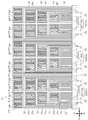
- FIG. 4 is a plan view illustrating an example of a pattern including a dummy pattern and a resistance setting unit.
- the dummy pattern DP is a slit-like pattern provided on each detection electrode 21a.
- a plurality of dummy patterns DP extending in the Y1-Y2 direction are provided in parallel on the detection electrode 21a. Thereby, a line and space region of the detection electrode 21a is formed.
- the dummy pattern DP When the dummy pattern DP is provided, it is desirable to match the width and pitch of the line & space of each detection electrode 21a by the dummy pattern DP with the width and pitch of the line & space in the equidistant region S1 of the plurality of lead wires 22. In addition, it is desirable that the line and space width and pitch of the folded pattern 23a juxtaposed with the equidistant region S1 are also matched with the line and space width and pitch of the equidistant region S1. Thereby, the same line & space is provided in the wide area
- the capacitive sensor according to the present invention since the capacitive sensor according to the present invention has a single layer structure and is excellent in ESD resistance, it is useful for a large touch panel having a light-transmitting conductive film and is difficult to be visually recognized by a user. A light pattern can be formed.
Landscapes
- Engineering & Computer Science (AREA)
- Physics & Mathematics (AREA)
- General Physics & Mathematics (AREA)
- General Engineering & Computer Science (AREA)
- Theoretical Computer Science (AREA)
- Human Computer Interaction (AREA)
- Position Input By Displaying (AREA)
- Measurement Of Length, Angles, Or The Like Using Electric Or Magnetic Means (AREA)
Abstract
Description
図1は、本実施形態に係る静電容量式センサの導電パターンを例示する平面図である。
図1に表したように、本実施形態に係る静電容量式センサは、基材10に単層構造の透光性導電膜のパターン20が設けられた構成を備える。パターン20は、検知パターン21と、引き出し配線22と、抵抗設定部23と、を有する。
図2(a)には抵抗設定部23を備えていない配線パターンが表され、図2(b)には抵抗設定部23を備えた配線パターンが表される。なお、説明の便宜上、図2(a)および(b)にはパターン20の一部のみが表される。
D1/D2=L1/L2 …(1)
D1/D2<L1’/L2 …(2)
本実施形態に係る静電容量式センサにおいては、隣り合う複数の検知電極21aの間に静電容量が形成される。検知電極21aの表面に指を接触または接近させると、指と、指に近い検知電極21aとの間に静電容量が形成されるため、検知電極21aから検出される電流値を計測することで、複数の検知電極21aのどの電極に指が最も接近しているかを検知できる。
パターン20を形成する透光性導電膜は導電性の金属ナノワイヤを含んでいる。この金属ナノワイヤの材質は限定されない。金属ナノワイヤを構成する材料として、Ag、Au、Ni、Cu、Pd、Pt、Rh、Ir、Ru、Os、Fe、Co、Snから選択される1種類以上の金属元素を含む材料が例示される。金属ナノワイヤの平均短軸径は限定されない。金属ナノワイヤの平均短軸径は、1nmよりも大きく500nm以下であることが好ましい。金属ナノワイヤの平均長軸長は、限定されない。金属ナノワイヤの平均長軸長は、1μmよりも大きく1000μm以下であることが好ましい。
次に、抵抗設定部23の他の例について説明する。
図3(a)~(c)は抵抗設定部の他の例について説明する平面図である。なお、説明の便宜上、図3(a)~(c)にはパターン20の一部のみが表される。
ダミーパターンDPは、各検知電極21aに設けられたスリット状のパターンである。検知電極21aには、Y1-Y2方向に延びるダミーパターンDPが複数本平行に設けられる。これにより、検知電極21aのライン&スペースの領域が構成される。
20…パターン
21…検知パターン
21a…検知電極
22…引き出し配線
23…抵抗設定部
23a…折り返しパターン
30…外部端子領域
231…直線パターン部
232…接続パターン部
S1…等間隔領域
Claims (7)
- 基材に透光性導電膜のパターンが設けられた静電容量式センサであって、
前記透光性導電膜は金属ナノワイヤを含み、
前記パターンは、
複数の検知電極が間隔を置いて配列された検知パターンと、
前記複数の検知電極のそれぞれから第1方向に直線状に延在する複数の引き出し配線と、
前記複数の引き出し配線の少なくともいずれかに接続され、前記第1方向と非平行な方向に延在する部分を含む抵抗設定部と、を有することを特徴とする静電容量式センサ。 - 前記抵抗設定部は、折り返しパターンを含む、請求項1に記載の静電容量式センサ。
- 前記複数の引き出し配線は、前記第1方向と直交する第2方向に一定の第1ピッチで配置される等間隔領域を含み、
前記折り返しパターンは、前記第2方向に前記等間隔領域と並置され、
前記折り返しパターンは、前記第1方向に直線状に延在する複数の直線パターン部を含む、請求項2に記載の静電容量式センサ。 - 前記複数の直線パターン部のそれぞれの幅は前記引き出し配線の幅と等しく、前記複数の直線パターン部の前記第2方向のピッチは前記第1ピッチと等しい、請求項3に記載の静電容量式センサ。
- 前記第1方向は、前記検知パターンから外部端子領域に向かう方向であり、
前記複数の検知電極は前記第1方向に配列され、
前記抵抗設定部は、少なくとも前記外部端子領域に最も近い検知電極から延在する前記引き出し配線に接続されている、請求項1から請求項4のいずれか1項に記載の静電容量式センサ。 - 前記複数の検知電極のそれぞれから延出する前記引き出し配線を含む配線パターンの抵抗値は互いに等しい、請求項1から請求項5のいずれか1項に記載の静電容量式センサ。
- 前記金属ナノワイヤは銀ナノワイヤを含むことを特徴とする、請求項1から請求項6のいずれか1項に記載の静電容量式センサ。
Priority Applications (6)
| Application Number | Priority Date | Filing Date | Title |
|---|---|---|---|
| KR1020187013821A KR101985636B1 (ko) | 2015-01-16 | 2015-10-29 | 정전 용량식 센서 |
| CN201580072637.4A CN107111402B (zh) | 2015-01-16 | 2015-10-29 | 电容式传感器 |
| JP2016569232A JP6339700B2 (ja) | 2015-01-16 | 2015-10-29 | 静電容量式センサ |
| EP15877931.4A EP3246797B1 (en) | 2015-01-16 | 2015-10-29 | Capacitive sensor |
| KR1020177017357A KR101931897B1 (ko) | 2015-01-16 | 2015-10-29 | 정전 용량식 센서 |
| US15/642,605 US10564010B2 (en) | 2015-01-16 | 2017-07-06 | Capacitive sensor |
Applications Claiming Priority (2)
| Application Number | Priority Date | Filing Date | Title |
|---|---|---|---|
| JP2015007253 | 2015-01-16 | ||
| JP2015-007253 | 2015-01-16 |
Related Child Applications (1)
| Application Number | Title | Priority Date | Filing Date |
|---|---|---|---|
| US15/642,605 Continuation US10564010B2 (en) | 2015-01-16 | 2017-07-06 | Capacitive sensor |
Publications (1)
| Publication Number | Publication Date |
|---|---|
| WO2016113979A1 true WO2016113979A1 (ja) | 2016-07-21 |
Family
ID=56405536
Family Applications (1)
| Application Number | Title | Priority Date | Filing Date |
|---|---|---|---|
| PCT/JP2015/080502 Ceased WO2016113979A1 (ja) | 2015-01-16 | 2015-10-29 | 静電容量式センサ |
Country Status (6)
| Country | Link |
|---|---|
| US (1) | US10564010B2 (ja) |
| EP (1) | EP3246797B1 (ja) |
| JP (2) | JP6339700B2 (ja) |
| KR (2) | KR101931897B1 (ja) |
| CN (1) | CN107111402B (ja) |
| WO (1) | WO2016113979A1 (ja) |
Cited By (1)
| Publication number | Priority date | Publication date | Assignee | Title |
|---|---|---|---|---|
| JP2020042806A (ja) * | 2018-09-10 | 2020-03-19 | 三星ディスプレイ株式會社Samsung Display Co.,Ltd. | ディスプレイ装置 |
Families Citing this family (6)
| Publication number | Priority date | Publication date | Assignee | Title |
|---|---|---|---|---|
| CN105158582B (zh) * | 2015-09-29 | 2018-03-09 | 北京工业大学 | 一种变间距叉指型相邻电容传感器 |
| KR101609992B1 (ko) * | 2015-10-05 | 2016-04-06 | 주식회사 지2터치 | 터치 스크린 패널 |
| KR102555500B1 (ko) * | 2017-12-18 | 2023-07-12 | 삼성에스디아이 주식회사 | 전극 조립체 |
| GB2572835B (en) * | 2018-04-13 | 2021-05-19 | Peratech Holdco Ltd | Sensing physical attributes |
| KR102741706B1 (ko) * | 2019-12-30 | 2024-12-12 | 엘지디스플레이 주식회사 | 터치 디스플레이 장치 |
| JP2023037328A (ja) * | 2021-09-03 | 2023-03-15 | 株式会社ジャパンディスプレイ | センサモジュール、およびセンサモジュールを備える表示装置 |
Citations (3)
| Publication number | Priority date | Publication date | Assignee | Title |
|---|---|---|---|---|
| JP2010140041A (ja) * | 2006-03-02 | 2010-06-24 | Au Optronics Corp | 信号伝送時のrc効果を軽減する表示パネル及び関連製作方法 |
| JP2014182436A (ja) * | 2013-03-18 | 2014-09-29 | Fujifilm Corp | タッチパネルおよび保護層形成用樹脂組成物 |
| WO2015005319A1 (ja) * | 2013-07-12 | 2015-01-15 | 富士フイルム株式会社 | 配線基板 |
Family Cites Families (20)
| Publication number | Priority date | Publication date | Assignee | Title |
|---|---|---|---|---|
| US7973771B2 (en) | 2007-04-12 | 2011-07-05 | 3M Innovative Properties Company | Touch sensor with electrode array |
| JP5060845B2 (ja) * | 2007-06-27 | 2012-10-31 | 株式会社ジャパンディスプレイイースト | 画面入力型画像表示装置 |
| WO2009060717A1 (ja) | 2007-11-07 | 2009-05-14 | Konica Minolta Holdings, Inc. | 透明電極及び透明電極の製造方法 |
| CN101464757A (zh) * | 2007-12-21 | 2009-06-24 | 清华大学 | 触摸屏及显示装置 |
| CN101458601B (zh) * | 2007-12-14 | 2012-03-14 | 清华大学 | 触摸屏及显示装置 |
| JP5103254B2 (ja) * | 2008-04-16 | 2012-12-19 | 株式会社ジャパンディスプレイイースト | 静電容量方式タッチパネルおよびそれを備える画面入力型表示装置 |
| JP4889685B2 (ja) * | 2008-06-04 | 2012-03-07 | 三菱電機株式会社 | タッチパネルおよびそれを備えた表示装置 |
| JP5249806B2 (ja) | 2009-02-16 | 2013-07-31 | グンゼ株式会社 | タッチスイッチ |
| US8279194B2 (en) * | 2009-05-22 | 2012-10-02 | Elo Touch Solutions, Inc. | Electrode configurations for projected capacitive touch screen |
| KR20110111007A (ko) * | 2010-04-02 | 2011-10-10 | 이화여자대학교 산학협력단 | L/d 광학변환 및 광학분할을 위한 옥타하이드로-바이나프톨 유도체 |
| KR101274649B1 (ko) * | 2010-05-27 | 2013-06-12 | 엘지디스플레이 주식회사 | 터치 패널 일체형 액정 표시 장치 및 이의 제조 방법 |
| TWI403937B (zh) * | 2010-06-03 | 2013-08-01 | Au Optronics Corp | 觸控顯示器及其觸控顯示基板 |
| JP2012033466A (ja) | 2010-07-02 | 2012-02-16 | Fujifilm Corp | 導電層転写材料、及びタッチパネル |
| US9535543B2 (en) * | 2010-07-14 | 2017-01-03 | Lg Innotek Co., Ltd. | Touch panel and method for manufacturing the same |
| TWI471642B (zh) * | 2010-09-24 | 2015-02-01 | Wintek Corp | Touch panel structure and its touch display panel |
| JP5797451B2 (ja) * | 2011-05-12 | 2015-10-21 | 富士通コンポーネント株式会社 | タッチパネル |
| JP5822637B2 (ja) * | 2011-10-12 | 2015-11-24 | 三菱電機株式会社 | タッチパネルおよびそれを備える表示装置 |
| KR101976089B1 (ko) * | 2012-08-27 | 2019-05-10 | 삼성디스플레이 주식회사 | 터치 스크린 패널 |
| JP2014157400A (ja) | 2013-02-14 | 2014-08-28 | Dainippon Printing Co Ltd | 画像表示装置 |
| JP5739554B2 (ja) * | 2014-01-29 | 2015-06-24 | 株式会社ワンダーフューチャーコーポレーション | タッチパネル、タッチパネルの製造方法、及びタッチパネル一体型表示装置 |
-
2015
- 2015-10-29 JP JP2016569232A patent/JP6339700B2/ja not_active Expired - Fee Related
- 2015-10-29 CN CN201580072637.4A patent/CN107111402B/zh not_active Expired - Fee Related
- 2015-10-29 KR KR1020177017357A patent/KR101931897B1/ko not_active Expired - Fee Related
- 2015-10-29 WO PCT/JP2015/080502 patent/WO2016113979A1/ja not_active Ceased
- 2015-10-29 EP EP15877931.4A patent/EP3246797B1/en not_active Not-in-force
- 2015-10-29 KR KR1020187013821A patent/KR101985636B1/ko not_active Expired - Fee Related
-
2017
- 2017-07-06 US US15/642,605 patent/US10564010B2/en not_active Expired - Fee Related
-
2018
- 2018-04-19 JP JP2018080445A patent/JP6630393B2/ja not_active Expired - Fee Related
Patent Citations (3)
| Publication number | Priority date | Publication date | Assignee | Title |
|---|---|---|---|---|
| JP2010140041A (ja) * | 2006-03-02 | 2010-06-24 | Au Optronics Corp | 信号伝送時のrc効果を軽減する表示パネル及び関連製作方法 |
| JP2014182436A (ja) * | 2013-03-18 | 2014-09-29 | Fujifilm Corp | タッチパネルおよび保護層形成用樹脂組成物 |
| WO2015005319A1 (ja) * | 2013-07-12 | 2015-01-15 | 富士フイルム株式会社 | 配線基板 |
Non-Patent Citations (1)
| Title |
|---|
| See also references of EP3246797A4 * |
Cited By (4)
| Publication number | Priority date | Publication date | Assignee | Title |
|---|---|---|---|---|
| JP2020042806A (ja) * | 2018-09-10 | 2020-03-19 | 三星ディスプレイ株式會社Samsung Display Co.,Ltd. | ディスプレイ装置 |
| JP7416585B2 (ja) | 2018-09-10 | 2024-01-17 | 三星ディスプレイ株式會社 | ディスプレイ装置 |
| US11957026B2 (en) | 2018-09-10 | 2024-04-09 | Samsung Display Co., Ltd. | Display device |
| US12262617B2 (en) | 2018-09-10 | 2025-03-25 | Samsung Display Co., Ltd. | Display device |
Also Published As
| Publication number | Publication date |
|---|---|
| US10564010B2 (en) | 2020-02-18 |
| JPWO2016113979A1 (ja) | 2017-11-02 |
| KR101931897B1 (ko) | 2018-12-21 |
| CN107111402A (zh) | 2017-08-29 |
| EP3246797A4 (en) | 2018-08-15 |
| US20170307413A1 (en) | 2017-10-26 |
| JP6339700B2 (ja) | 2018-06-06 |
| KR20180055930A (ko) | 2018-05-25 |
| EP3246797B1 (en) | 2021-02-24 |
| KR101985636B1 (ko) | 2019-06-03 |
| JP6630393B2 (ja) | 2020-01-15 |
| EP3246797A1 (en) | 2017-11-22 |
| JP2018142347A (ja) | 2018-09-13 |
| KR20170087498A (ko) | 2017-07-28 |
| CN107111402B (zh) | 2020-10-20 |
Similar Documents
| Publication | Publication Date | Title |
|---|---|---|
| JP6339700B2 (ja) | 静電容量式センサ | |
| JP6605082B2 (ja) | 静電容量式センサ | |
| CN104915048A (zh) | 导电膜和包括该导电膜的触摸面板 | |
| CN106126004B (zh) | 触摸面板和包括触摸面板的显示装置 | |
| WO2016123811A1 (zh) | 电容触摸屏及其与柔性电路板的组合 | |
| US20180307341A1 (en) | Touch devices including nanoscale conductive films | |
| CN104346015A (zh) | 触摸窗口和包括其的触摸装置 | |
| JP6096375B2 (ja) | 静電容量式センサ | |
| KR101577199B1 (ko) | 터치패널 및 표시장치 | |
| JP2016058319A (ja) | 電極及びその製造方法、並びに前記電極を備えるタッチパネル及び有機el基板 | |
| US20140353020A1 (en) | Touch panel | |
| JP6891881B2 (ja) | 導電性素子、入力装置および電子機器 | |
| KR102354108B1 (ko) | 터치 패널과 연성 인쇄회로기판의 접합 구조체 | |
| KR102119834B1 (ko) | 터치 윈도우 및 이를 포함하는 디스플레이 장치 | |
| WO2014034468A1 (ja) | 透明導電性素子およびその製造方法、入力装置、電子機器、ならびに導電部の形成方法 | |
| JP2017068844A (ja) | 透明導電基板、及び静電容量型タッチパネル | |
| JP2017111478A (ja) | 静電容量式タッチセンサ用シート及びその製造方法 | |
| KR102303064B1 (ko) | 터치 윈도우 | |
| KR102238162B1 (ko) | 터치패널 및 그 제조방법 | |
| JP2014074839A (ja) | 表示装置 | |
| KR20150039041A (ko) | 터치 윈도우 및 이를 포함하는 디스플레이 |
Legal Events
| Date | Code | Title | Description |
|---|---|---|---|
| 121 | Ep: the epo has been informed by wipo that ep was designated in this application |
Ref document number: 15877931 Country of ref document: EP Kind code of ref document: A1 |
|
| ENP | Entry into the national phase |
Ref document number: 2016569232 Country of ref document: JP Kind code of ref document: A |
|
| ENP | Entry into the national phase |
Ref document number: 20177017357 Country of ref document: KR Kind code of ref document: A |
|
| REEP | Request for entry into the european phase |
Ref document number: 2015877931 Country of ref document: EP |
|
| NENP | Non-entry into the national phase |
Ref country code: DE |