WO2016114077A1 - データ判定装置、データ判定方法及びプログラム - Google Patents
データ判定装置、データ判定方法及びプログラム Download PDFInfo
- Publication number
- WO2016114077A1 WO2016114077A1 PCT/JP2015/085742 JP2015085742W WO2016114077A1 WO 2016114077 A1 WO2016114077 A1 WO 2016114077A1 JP 2015085742 W JP2015085742 W JP 2015085742W WO 2016114077 A1 WO2016114077 A1 WO 2016114077A1
- Authority
- WO
- WIPO (PCT)
- Prior art keywords
- communication
- data
- determination
- state
- permission
- Prior art date
- Legal status (The legal status is an assumption and is not a legal conclusion. Google has not performed a legal analysis and makes no representation as to the accuracy of the status listed.)
- Ceased
Links
Images


Classifications
-
- H—ELECTRICITY
- H04—ELECTRIC COMMUNICATION TECHNIQUE
- H04L—TRANSMISSION OF DIGITAL INFORMATION, e.g. TELEGRAPHIC COMMUNICATION
- H04L9/00—Cryptographic mechanisms or cryptographic arrangements for secret or secure communications; Network security protocols
- H04L9/36—Cryptographic mechanisms or cryptographic arrangements for secret or secure communications; Network security protocols with means for detecting characters not meant for transmission
-
- G—PHYSICS
- G06—COMPUTING OR CALCULATING; COUNTING
- G06F—ELECTRIC DIGITAL DATA PROCESSING
- G06F21/00—Security arrangements for protecting computers, components thereof, programs or data against unauthorised activity
- G06F21/50—Monitoring users, programs or devices to maintain the integrity of platforms, e.g. of processors, firmware or operating systems
- G06F21/55—Detecting local intrusion or implementing counter-measures
- G06F21/554—Detecting local intrusion or implementing counter-measures involving event detection and direct action
-
- G—PHYSICS
- G06—COMPUTING OR CALCULATING; COUNTING
- G06F—ELECTRIC DIGITAL DATA PROCESSING
- G06F21/00—Security arrangements for protecting computers, components thereof, programs or data against unauthorised activity
- G06F21/50—Monitoring users, programs or devices to maintain the integrity of platforms, e.g. of processors, firmware or operating systems
- G06F21/55—Detecting local intrusion or implementing counter-measures
- G06F21/56—Computer malware detection or handling, e.g. anti-virus arrangements
- G06F21/567—Computer malware detection or handling, e.g. anti-virus arrangements using dedicated hardware
-
- H—ELECTRICITY
- H04—ELECTRIC COMMUNICATION TECHNIQUE
- H04L—TRANSMISSION OF DIGITAL INFORMATION, e.g. TELEGRAPHIC COMMUNICATION
- H04L63/00—Network architectures or network communication protocols for network security
- H04L63/02—Network architectures or network communication protocols for network security for separating internal from external traffic, e.g. firewalls
- H04L63/0227—Filtering policies
- H04L63/0263—Rule management
-
- H—ELECTRICITY
- H04—ELECTRIC COMMUNICATION TECHNIQUE
- H04L—TRANSMISSION OF DIGITAL INFORMATION, e.g. TELEGRAPHIC COMMUNICATION
- H04L63/00—Network architectures or network communication protocols for network security
- H04L63/14—Network architectures or network communication protocols for network security for detecting or protecting against malicious traffic
- H04L63/1408—Network architectures or network communication protocols for network security for detecting or protecting against malicious traffic by monitoring network traffic
- H04L63/1416—Event detection, e.g. attack signature detection
-
- H—ELECTRICITY
- H04—ELECTRIC COMMUNICATION TECHNIQUE
- H04L—TRANSMISSION OF DIGITAL INFORMATION, e.g. TELEGRAPHIC COMMUNICATION
- H04L63/00—Network architectures or network communication protocols for network security
- H04L63/14—Network architectures or network communication protocols for network security for detecting or protecting against malicious traffic
- H04L63/1441—Countermeasures against malicious traffic
- H04L63/145—Countermeasures against malicious traffic the attack involving the propagation of malware through the network, e.g. viruses, trojans or worms
Definitions
- the present invention relates to a data determination device, a data determination method, and a program.
- the present invention relates to a data determination device, a data determination method, and a program for detecting an attack intrusion into a network.
- the permitted communication such as the destination address and source address pair and protocol is defined by utilizing the fixed network communication of the industrial control system. Then, the intrusion detection system takes a white list type countermeasure for detecting an intrusion even for an unknown attack by making an abnormality other than permitted communication (see Patent Documents 1 and 2).
- Patent Document 2 a method for defining a communication sequence to be permitted and managing a communication state such as unconnected, in communication, and abnormal processing in each communication sequence has been proposed (see Patent Document 2). Furthermore, a method for detecting network intrusion due to execution of an unauthorized program by defining an application that permits communication has also been proposed (see Patent Document 3).
- Stuxnet In recent years, advanced attacks represented by Stuxnet have been conducted targeting industrial control systems. Stuxnet hijacks a server that is permitted to communicate, and causes attack communication to be included in communication defined as normal. For this reason, the attack communication has a problem that it passes through the white list type countermeasures of Patent Documents 1 and 2.
- Patent Document 3 communication is linked with an application program on a local host, and when communication occurs, it is determined whether or not the application program that performs communication is permitted to perform communication, and the communication is blocked. .
- communication cannot be blocked if a vulnerability inherent in an application program that is permitted to communicate is exploited.
- An object of the present invention is to provide a data determination device that can take over a server that is permitted to communicate and detect an intrusion even against an attack that causes attack communication to be included in communication defined as normal.
- the data determination device is: A state transition model storage unit that stores a state transition model that represents a state transition between operation states of a plurality of operation states; Based on the state transition model, a state management unit that holds the operation state of the own device, A communication permission list storage unit that stores communication permission data permitting communication in each operation state of the plurality of operation states as a communication permission list; A communication unit for acquiring communication data as communication determination data; The communication determination data acquired by the communication unit is acquired, the operation state of the own device held by the state management unit is acquired as a current operation state, and the current operation state and the communication permission list are used. And a determination unit that determines whether the communication determination data is communication permission data that is permitted to be communicated in the current operation state.
- communication permission data that permits communication for each operation state included in the state transition model is set as a communication permission list, and the determination unit determines the current operation state and the communication permission list. Is used to determine whether or not the communication determination data is communication permission data that is permitted to be communicated in the current operation state. An intrusion can be detected even against an attack that is confused.
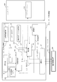
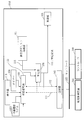
- FIG. 1 is a block configuration diagram of a data determination device according to Embodiment 1.
- FIG. FIG. 2 is a block configuration diagram of a data determination apparatus that performs an operation different from that of the data determination apparatus in FIG. 1.
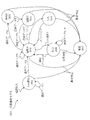
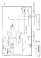
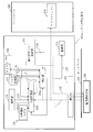
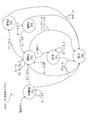
- FIG. 3 is a diagram illustrating an example of a state transition model of the data determination device according to the first embodiment.
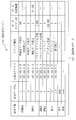
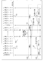
- FIG. 3 is a configuration diagram of a communication permission list according to the first embodiment.
- FIG. 2 is a hardware configuration diagram of the data determination device according to the first embodiment.
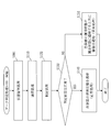
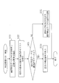
- FIG. 3 is a flowchart showing a data determination method and data determination process of the data determination apparatus according to the first embodiment.
- FIG. 3 is a flowchart showing determination processing by a determination unit according to Embodiment 1;
- FIG. 5 is a block configuration diagram of a data determination device according to a second embodiment.
- FIG. 5 is a block configuration diagram of a data determination device according to a third embodiment.
- FIG. 6 is a block configuration diagram of a data determination device according to a fourth embodiment.
- FIG. 10 is a diagram illustrating an example of a state transition model of the data determination device according to the fourth embodiment.
- FIG. 9 is a flowchart showing a data determination method and data determination process of the data determination apparatus according to the fourth embodiment.
- FIG. 9 is a flowchart showing determination processing by a determination unit according to Embodiment 4;
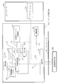
- Embodiment 1 FIG. *** Explanation of configuration *** The block configuration of the data determination apparatus 101 according to the present embodiment will be described with reference to FIG.
- a system including the data determination device 101, the monitoring control device 200, and the controller 300 is referred to as a data determination system 500.
- the data determination device 101 is connected to the network 102 and mediates communication data communicated between the monitoring control device 200 and the controller 300 and determines the communication data.
- the data determination device 101 is an intrusion detection device or intrusion detection system that detects an attack that enters the network 102.
- the controller 300 is provided in an industrial control system, for example.
- the controller 300 includes an application 310.
- the application 310 transmits the transmission data 112 to the data determination apparatus 101. Further, the application 310 receives the reception data 111 from the monitoring control device 200.
- the reception data 111 and the transmission data 112 that are determined while the data determination apparatus 101 communicates are also referred to as communication determination data 109.
- the monitoring control device 200 is a server that monitors and controls an industrial control system, for example.
- the data determination apparatus 101 mediates the reception data 111 received from the monitoring control apparatus 200 via the network 102 to the controller 300.
- the data determination apparatus 101 mediates the transmission data 112 transmitted by the controller 300 to the monitoring control apparatus 200 via the network 102.
- the data determination apparatus 101 performs data determination processing for detecting an intrusion of an attack in the process of mediating the reception data 111 and the transmission data 112.
- the data determination apparatus 101 includes a state management unit 103, a timer 104, a communication permission list storage unit 105, a determination unit 106, a communication unit 107, an alarm unit 108, an operation unit 110, and a state transition model storage unit 130.
- the state transition model storage unit 130 stores a state transition model 1031 that represents a state transition between operation states of a plurality of operation states.
- the state transition model storage unit 130 stores a state transition model 1031 that transitions between operation states of a plurality of operation states in accordance with acquired information 1033 acquired by the own device.
- the own device is the data determination device 101 itself.
- the acquisition information 1033 is an element that changes the state of the data determination apparatus 101.
- the acquisition information 1033 includes communication data acquired through communication, an operation signal 1101 indicating that an operation on the device itself has been received, and a timer signal 1041 output from the timer 104.
- the state management unit 103 holds the operation state of the own device, that is, the data determination device 101.
- the communication permission list storage unit 105 stores, as the communication permission list 114, communication permission data 119 that permits communication in each operation state of a plurality of operation states.
- the communication unit 107 acquires communication data as communication determination data 109.
- the determination unit 106 acquires the communication determination data 109 acquired by the communication unit 107 and acquires the operation state 1032 of the own apparatus held by the state management unit 103 as the current operation state 113.
- the determination unit 106 determines whether or not the communication determination data 109 is communication permission data 119 permitted to communicate in the current operation state 113 using the current operation state 113 and the communication permission list 114.
- the communication unit 107 connects to the monitoring control device 200 via the network 102.
- the communication unit 107 receives the reception data 111 from the monitoring control device 200 via the network 102 and outputs the received reception data 111 to the determination unit 106.
- the communication unit 107 transmits the input transmission data 112 to the monitoring control device 200 via the network 102.
- the communication unit 107 is a network input / output unit.
- the state management unit 103 manages the operation state of the data determination apparatus 101 with the state transition model 1031.
- the state transition model 1031 is set in advance and stored in the storage area of the data determination apparatus 101.
- the operation unit 110 is a button or a touch panel operated by a human.
- the operation unit 110 outputs an operation signal 1101 indicating that an operation on the device itself has been accepted.
- the timer 104 measures the time during which the operation state of the own device continues. That is, the timer 104 measures the time in the time constraint when there is a time constraint in communication.
- the communication permission list storage unit 105 is a storage area for storing the communication permission list 114.
- the determination unit 106 acquires the reception data 111 or the transmission data 112, the current operation state 113 output by the state management unit 103, and the communication permission list 114 stored by the communication permission list storage unit 105.
- the determination unit 106 compares the acquired reception data 111 or transmission data 112 with the current operation state 113 and the communication permission list 114 to determine whether the reception data 111 or transmission data 112 is permitted, The determination result 115 is output. If the determination unit 106 determines that the communication determination data 109 is not the communication permission data 119, the determination unit 106 blocks communication. That is, the determination unit 106 blocks communication when the determination result 115 is abnormal.
- the alarm unit 108 When the determination unit 106 determines that the communication determination data 109 is not the communication permission data 119, the alarm unit 108 outputs an alarm indicating that an abnormality has been detected. That is, the alarm unit 108 issues an alarm when the determination result 115 is abnormal.
- the alarm issued by the alarm unit 108 may be visual such as a lamp, or may be issued to another server via a network.
- the state management unit 103 transitions the operation state 1032 of the own apparatus based on the state transition model 1031. Further, when the determination unit 106 determines that the communication determination data 109 is not the communication permission data 119, the state management unit 103 shifts the operation state 1032 of the own apparatus to an abnormal state. Note that the state management unit 103 may only change the state when it is determined to be normal. As described above, the state management unit 103 holds the current operation state 113 of the data determination apparatus 101 that is the own apparatus.
- a data determination apparatus 101a that performs an operation different from that of the data determination apparatus 101 in FIG. 1 will be described with reference to FIG.
- the determination unit 106 communicates the reception data 111 or the transmission data 112 after determining the communication determination data 109.
- the determination unit 106 when the determination result 115 is abnormal, the determination unit 106 cannot block communication.
- states 301 to 307 are examples of a plurality of operation states 3001. Moreover, between each state is an example of between each operation state 3002 of a plurality of operation states.
- the data determination apparatus 101 transitions to the NW construction state 301 when the power is turned on, and performs communication necessary for NW construction.
- communication necessary for NW construction is communication data 1.
- network construction is also referred to as NW construction.
- the state transition model 1031 when the NW construction is completed and the communication data 2 is received, the state transition model 1031 shifts to the driving A state 302.
- the operation state is further defined according to the prescribed communication order To do.
- the state transition model 1031 of FIG. 3 when communication data 4 is communicated, a transition is made to operation B state 303, communication data 5 is transitioned to operation C state 304, and communication data 6 is communicated to transition to operation A state 302. Is defined as In this way, the transition conditions to the respective operation states may be assigned to the communication data 4, 5, 6.
- the timer when there is communication data 7 with time restriction, the timer may be turned on, the process may be shifted to the waiting state 305, and the operation A state 302 may be restored when the timer is turned off.
- the timer signal 1041 is a signal indicating on / off of the timer.
- the operation may be shifted to the maintenance state 306 by a human operation 1 and communication necessary for maintenance, for example, communication data 8 and 9 may be performed.
- the operation A state 302 is entered.
- the transition when performing a state transition based on communication data, the transition may be performed only when the determination result of the determination unit 106 is normal. In each state, if the determination result of the determination unit 106 is abnormal, the state may be changed to an abnormal state 307.
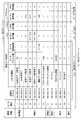
- FIG. 4 is an example of the communication permission list 114 permitted in each operation state held by the state management unit 103.
- the communication permission list 114 in FIG. 4 is an example, and does not necessarily have to be as shown in FIG.
- the communication permission list 114 includes items such as an operation state, a communication data number, a transmission source address, a command type, a data size upper limit, and a data setting range. These items are arbitrary, and other items may be used as long as they can specify communication data.
- the data determination apparatus 101 is a computer.
- the data determination apparatus 101 includes hardware such as a processor 901, an auxiliary storage device 902, a memory 903, a communication device 904, an input interface 905, and a display interface 906.
- the processor 901 is connected to other hardware via the signal line 910, and controls these other hardware.
- the input interface 905 is connected to the input device 907.
- the display interface 906 is connected to the display 908.
- the processor 901 is an IC (Integrated Circuit) that performs processing.
- the processor 901 is, for example, a CPU (Central Processing Unit), a DSP (Digital Signal Processor), or a GPU (Graphics Processing Unit).
- the auxiliary storage device 902 is, for example, a ROM (Read Only Memory), a flash memory, or an HDD (Hard Disk Drive).
- the memory 903 is, for example, a RAM (Random Access Memory).
- the communication device 904 includes a receiver 9041 that receives data and a transmitter 9042 that transmits data.
- the communication device 904 is, for example, a communication chip or a NIC (Network Interface Card).
- the input interface 905 is a port to which the cable 911 of the input device 907 is connected.
- the input interface 905 is, for example, a USB (Universal Serial Bus) terminal.
- the display interface 906 is a port to which the cable 912 of the display 908 is connected.
- the display interface 906 is, for example, a USB terminal or an HDMI (registered trademark) (High Definition Multimedia Interface) terminal.
- the input device 907 is, for example, a mouse, a keyboard, or a touch panel.
- the display 908 is, for example, an LCD (Liquid Crystal Display).
- auxiliary storage device 902 functions of the state management unit 103, the determination unit 106, and the alarm unit 108 (hereinafter, the state management unit 103, the determination unit 106, and the alarm unit 108 are collectively referred to as “part”) illustrated in FIG.
- a program for realizing is stored.
- the program that realizes the function of “unit” included in the data determination apparatus 101 is also referred to as a data determination program.
- the program that realizes the function of “unit” may be a single program or a plurality of programs.
- This program is loaded into the memory 903, read into the processor 901, and executed by the processor 901. Further, the auxiliary storage device 902 also stores an OS (Operating System).
- OS Operating System
- the processor 901 executes a program that realizes the function of “unit” while executing the OS.
- the data determination apparatus 101 may include a plurality of processors 901.
- a plurality of processors 901 may execute a program for realizing the function of “unit” in cooperation with each other.
- information, data, signal values, and variable values indicating the results of the processing of “unit” are stored as files in the memory 903, the auxiliary storage device 902, or a register or cache memory in the processor 901.
- circuitry may be provided as “circuitry”. Further, “part” may be read as “circuit”, “process”, “procedure”, or “processing”. Further, “processing” may be read as “circuit”, “process”, “procedure”, or “part”. “Circuit” and “Circuitry” include not only the processor 901 but also other types of processing circuits such as a logic IC or GA (Gate Array) or ASIC (Application Specific Integrated Circuit) or FPGA (Field-Programmable Gate Array). It is a concept to include.
- GA Gate Array
- ASIC Application Specific Integrated Circuit
- FPGA Field-Programmable Gate Array
- a program product is a storage medium, a storage device, or the like on which a program that realizes the function described as a “part” is recorded. It is what you are loading.
- the data determination apparatus 101 includes the state transition model storage unit 130 that stores the state transition model 1031 and the communication permission list storage unit 105 that stores the communication permission data 119 as the communication permission list 114.
- the state management unit 103 executes the state management process S101 that holds the operation state 1032 of the own apparatus based on the state transition model 1031.
- the state management unit 103 transitions the operation state 1032 of the own device based on the state transition model 1031 and holds the latest operation state as the operation state 1032 of the own device.
- the communication unit 107 executes communication processing S110 that acquires communication data as communication determination data 109.
- the communication unit 107 acquires the reception data 111 or the transmission data 112 as communication determination data 109 that is a determination target.
- the determination unit 106 acquires the communication determination data 109 acquired in the communication process S110 and acquires the operation state 1032 of the own apparatus held in the state management process S101 as the current operation state 113.
- the determination unit 106 determines whether or not the communication determination data 109 is communication permission data 119 permitted to communicate in the current operation state 113 using the current operation state 113 and the communication permission list 114.
- the determination unit 106 outputs a determination result 115. If the determination result 115 is normal in S130, that is, if the communication determination data 109 is the communication permission data 119, the process proceeds to a normal process S140. In S130, when the determination result 115 is abnormal, that is, when the communication determination data 109 is not the communication permission data 119, the process proceeds to the abnormality process S150.
- the state management unit 103 changes the operation state 1032 of the own device based on the acquired communication determination data 109 and the state transition model 1031.
- the state management unit 103 shifts the operation state 1032 of the own apparatus to an abnormal state. Further, the alarm unit 108 notifies an alarm.
- the determination unit 106 acquires the communication determination data 109 and analyzes the acquired communication determination data 109.
- the determination unit 106 acquires the reception data 111 or the transmission data 112 as the communication determination data 109.
- the determination unit 106 analyzes the contents of the communication determination data 109 and extracts elements necessary for determination.
- the extracted elements are items described in the communication permission list 114, such as a communication data number, a transmission source address, a transmission destination address, a command type, and a response type.
- the determination unit 106 acquires the current operation state 113 from the state management unit 103. Further, the determination unit 106 acquires the communication permission list 114 from the communication permission list storage unit 105.
- the determination unit 106 determines whether the communication determination data 109 is communication data permitted in the current operation state 113, that is, communication permission data 119, based on the current operation state 113 and the communication permission list 114. Determine whether. If the communication determination data 109 is the communication permission data 119, the process proceeds to S124. If the communication determination data 109 is not the communication permission data 119, that is, if the communication determination data 109 is not permitted, the process proceeds to S125.
- the determination unit 106 outputs a normal determination result 115.
- the determination unit 106 outputs an abnormality determination result 115 and blocks communication of the communication determination data 109. Or the determination part 106 does not need to interrupt
- the data determination apparatus 101 has the following configuration.
- a state management unit that manages an operation state in accordance with a state transition model that transitions according to one or more elements of communication data, external operation, and timer.
- B A communication permission list storage unit that stores a communication permission list that defines communication data to be permitted for each operation state.
- C Determining whether or not the communication data input to the data determination apparatus is normal using the current operation state output by the state management unit and the communication permission list stored in the communication permission list storage unit Department.
- D An alarm unit that issues an alarm based on the determination result output by the determination unit.
- the state management unit manages the operation state according to a state transition model that transitions according to the determination result output by the determination unit.
- the determination unit blocks communication data determined to be abnormal.
- the controller whose program has been rewritten by the Stuxnet induces a device failure by transmitting a command for changing the frequency at a high frequency to the frequency converter to be controlled.
- the data determination apparatus it is possible to take measures to detect such a high frequency change command by a timer.
- the transition to the maintenance state may be performed by communication data from a dedicated device that is guaranteed not to be taken over.
- deviation from the correct communication order can also be detected.
- Embodiment 2 FIG. In the present embodiment, differences from the first embodiment will be mainly described.
- the same components as those described in Embodiment 1 are denoted by the same reference numerals, and the description thereof may be omitted.
- the designer needs to set the state transition model 1031 and the communication permission list 114 in advance.
- a method for generating the state transition model 1031 and the communication permission list 114 from the acquired information history 151 will be described.
- attack data is not included in the acquired information history 151.
- the data determination apparatus 101b according to the present embodiment includes a history storage unit 153 and a list generation unit 152 in addition to the configuration of the first embodiment.
- the history storage unit 153 stores the history of acquired information as the acquired information history 151.
- the acquired information history 151 is a file in which acquired information acquired by the data determination apparatus 101b is stored, and is stored in a storage area of the data determination apparatus 101b.
- the acquired information history 151 is a history of acquired information acquired by the data determination apparatus 101b, and includes a communication history.
- the list generation unit 152 generates the state transition model 1031 and the communication permission list 114 based on the acquired information history 151. Note that generation of the state transition model 1031 and the communication permission list 114 may be performed by human work, and the list generation unit 152 may not be provided in the case of performing human work.
- FIG. 9 is a diagram illustrating a procedure for determining the operation state of the data determination apparatus 101b from the acquired information history 151 and generating the state transition model 1031.
- the list generation unit 152 automatically executes the list generation processing.
- FIG. 9 it is assumed that “A power on” to “T communication data 5” are obtained from the acquired information history 151.
- the outline of the state transition model generation process by the list generation unit 152 will be described with reference to FIG.
- the list generation unit 152 sets a waiting state if the elapsed time between successive communication data included in the acquired information history 151 is equal to or longer than the first time.
- the list generation unit 152 sets the time when the acquisition information other than the communication data is acquired as the first change point 701, and sets the first operation state before and after the first change point 701.
- the list generation unit 152 sets the second change point 702 as the second change point 702 when the transition communication data 703 determined to change the operation state in each first operation state is set as the second operation point 702.
- a state transition model is generated as a state.
- the list generation unit 152 extracts the transition communication data 703 using a clustering method.
- the list generation unit 152 sets communication data communicated in each operation state included in the state transition model in the communication permission list as communication permission data.
- the list generation unit 152 brings together the operation states in which the inclusion relationship is established in the communication permission data into one.
- step S ⁇ b> 601 the list generation unit 152 defines a “waiting” state if the elapsed time between communication data is equal to or greater than a certain time. It is defined that the timer is turned on at the time of transition to the wait state, and transitions to the next operation state when the timer is off.
- step S602 the list generation unit 152 sets the first change point 701 of the state when an input other than the communication data is generated, and sets a new first operation state between the first change points 701.
- “state 1” is defined from “A power-on” to “I communication data 5: timer on”, and “state 2” and “state 3” are defined similarly.
- the list generation unit 152 clusters the communication data between the first change points 701 determined in S602 in time series, and sets a new second operation state between the clusters.
- a Ward method, a K-average method, machine learning, or the like may be used.
- the second change point may be determined based on the specification.
- each communication data may be defined as the second change point. As shown in FIG. 9, in S603, “state 1-1”, “state 1-2”, “state 3-1”, and “state 3-2” are defined as the second operation state.
- FIG. 10 is a communication permission list generated from the state transition model
- FIG. 11 is a communication permission list after compilation.
- a method for generating a communication permission list from the state transition model generated by the method described in FIG. 9 will be described with reference to FIGS. 10 and 11.
- the list generation unit 152 extracts permitted communication data in each state of the previously generated state transition model, and makes a table of a communication permission list. At this time, the transition condition and the state of the transition destination are also summarized in a table.
- the list generation unit 152 summarizes a state in which an inclusion relationship is established in the communication data permitted in the communication permission list in FIG. 10.
- the states defined as the transition destination are also summarized. For example, as shown in FIG. 11, since the inclusion relationship is established between the state 1-2, the state 2, and the state 3-2, these are collectively referred to as the state 1-2, and the corresponding transition destinations are also collected.
- the data determination apparatus 101b includes a list generation unit that generates a state transition model and a communication permission list from the acquired information history.
- the list generation unit uses the following processing for generating the state transition model and the communication permission list.
- (1) A process of setting a waiting state if the elapsed time between communication data is equal to or greater than a certain value, turning on a timer when transitioning to the waiting state, and transitioning to the next state when the timer is off.
- (2) A process of setting an operation state change point when an input other than communication data is generated and setting a new operation state before and after the change point.
- (3) A process in which specific communication data is used as a change point in the operation state defined in (2), and before and after that, a new operation state is set.
- (4) In each operation state, a process of listing data communicated within the operation state as permitted communication data.
- (5) In (3), a process using a predetermined clustering method when obtaining the specific communication data.
- (6) A process for bringing together the operation states in which an inclusion relationship is established in the permitted communication data.
- the signatures attached to the state transition model and the communication permission list are verified and falsified. It has processing to detect.
- Embodiment 3 FIG. In the present embodiment, differences from Embodiments 1 and 2 will be mainly described. The same components as those described in the first and second embodiments are denoted by the same reference numerals, and the description thereof may be omitted.
- the data determination apparatus 101 is connected between the network 102 and the controller 300.
- the configuration of the data determination device 101c that can be installed between the server and the controller will be described.
- the block configuration of the data determination apparatus 101c according to the present embodiment will be described with reference to FIG.
- the data determination device 101c is connected to the monitoring control device 200 as a server via the network 102, and is connected to the controller 300 via the network 102a.
- the data determination apparatus 101c corresponds to each of the network 102 and the network 102a, and includes a communication unit 107 and a communication unit 107a.
- a block configuration of the data determination apparatus 101d that performs an operation different from that of the data determination apparatus 101c in FIG. 12 will be described with reference to FIG.
- the data determination device 101 d may be configured such that the determination unit 106 captures communication between the monitoring control device 200 and the controller 300.
- the monitoring control apparatus 200 and the controller 300 are connected to one network 102.
- the data determination apparatus 101c determines communication from the monitoring control apparatus 200 to the controller 300 and communication from the controller 300 to the monitoring control apparatus 200, as described in the first and second embodiments.
- the determination operation of the data determination apparatus 101c is the same as that of the first embodiment.
- the operation of the data determination apparatus 101d is the same as that of the data determination apparatus 101a of the first embodiment.
- a transmission destination address may be defined in addition to a transmission source address, a command type, a data size upper limit, a data setting range, and the like.
- the state determination unit, determination unit, and alarm unit constitute the data determination device as independent function blocks.
- the data determination apparatus may not be configured as described above, and the configuration of the data determination apparatus is arbitrary. You may implement
- the data determination device may be a data determination system including a plurality of devices instead of a single device.
- the function block of the data determination device is arbitrary as long as the function described in the embodiment can be realized, and the data determination device may be configured by any combination of these function blocks.
- Embodiments 1 to 3 have been described, a plurality of these three embodiments may be combined. Alternatively, one of these three embodiments may be partially implemented. Alternatively, a plurality of these three embodiments may be partially combined. In addition, these three embodiments may be implemented in any combination as a whole or in part. In addition, said embodiment is an essentially preferable illustration, Comprising: It does not intend restrict
- Embodiment 4 FIG. In the present embodiment, differences from the first embodiment will be mainly described.
- the basic operation of the data determination apparatus 101e according to the present embodiment is the same as that of the data determination apparatus 101 described in the first embodiment, but the configuration of the communication permission list 114e, the configuration of the state transition model 1031e, and the determination process S120e. This operation differs from the first embodiment.
- the same components as those in the first embodiment are denoted by the same reference numerals, and the description thereof may be omitted.
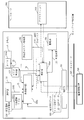
- the block configuration of the data determination apparatus 101e according to the present embodiment will be described with reference to FIG. FIG. 14 corresponds to FIG. 1 described in the first embodiment.
- the data determination apparatus 101e according to the present embodiment includes a flag management unit 177 in addition to the configuration of the data determination apparatus 101 described in the first embodiment.
- the timer 104, the state management unit 103, and the determination unit 106 described in the first embodiment are different from the first embodiment, in this embodiment, the timer 104e, the state management unit 103e, and the determination unit 106e To do. Therefore, in the data determination apparatus 101e according to the present embodiment, the functions of the flag management unit 177, the timer 104e, the state management unit 103e, and the determination unit 106e are added to the function of the “unit” described in the first embodiment.
- the flag management unit 177 manages flags.
- the flag management unit 177 inputs the flag value 15 that is the current value of the flag to the state management unit 103e and the determination unit 106e. Further, the flag set value 16 is input from the determination unit 106e.
- the timer 104e measures time. Specifically, the timer 104e subtracts the set value at a constant period, specifically 1 ms, and ends the subtraction when the value becomes 0.
- the timer 104e inputs the timer value 17, which is the current value, to the state management unit 103e and the determination unit 106e. Further, the timer set value 18 is input from the determination unit 106e.
- the timer 104e is an example of a timer unit 144 that measures time. Note that description of the timer signal 1041 described in Embodiment 1 is omitted.
- the state transition model storage unit 130 stores a state transition model 1031e having a configuration different from that of the state transition model 1031 described in the first embodiment.
- the communication permission list storage unit 105 stores a communication permission list 114e having a configuration different from that of the communication permission list 114 described in the first embodiment.
- communication permission list 114e as shown in FIG. 16, communication permission data 119e that permits communication in each operation state of a plurality of operation states, a permission condition 192 that permits communication of the communication permission data 119e, and a communication permission A communication permission rule 14 including a permission process 193 when data communication is permitted is stored.
- the determination unit 106e acquires the reception data 111 from the communication unit 107 and the transmission data 112 from the application 310, and determines the operation state of the own device held by the state management unit 103e. Obtained as the current operation state 113. Further, the determination unit 106e acquires the timer value 17 from the timer 104e and the flag value 15 from the flag management unit 177. The determination unit 106e uses the current operation state 113, the timer value 17, the flag value 15, and the communication permission list 114e so that the communication determination data 109 corresponds to the communication permission rule 14 that is permitted to communicate in the current operation state 113. It is determined whether or not.
- the determination unit 106e will be further described.
- the determination unit 106e manages the reception data 111 or the transmission data 112, the current operation state 113 output from the state management unit 103e, the communication permission list 114e stored in the communication permission list storage unit 105, and the flag management unit 177.
- the flag value 15 and the timer value 17 managed by the timer 104e are acquired.
- the determination unit 106e compares the acquired reception data 111 or transmission data 112 with the current operation state 113, the communication permission list 114e, the flag value 15, and the timer value 17, and the reception data 111 or transmission data 112 is permitted. It is determined whether or not it has been performed, and a determination result 115 is output.
- the determination unit 106e determines that the communication determination data 109 corresponds to the communication permission rule 14 included in the communication permission list 114e, the determination unit 106e permits communication and performs the action described in the corresponding communication permission rule 14, that is, the permission process 193. Execute. Specifically, the flag permission value described in the communication permission rule 14 is set as the flag setting value 16 for the flag management unit 177, or the timer permission value described in the communication permission rule 14 is set for the timer 104e. Or set as a timer set value 18. If the determination unit 106e determines that the communication determination data 109 does not correspond to the communication permission rule 14, the determination unit 106e blocks communication. That is, the determination unit 106e blocks communication when the determination result 115 is abnormal.
- the alarm unit 108 outputs an alarm indicating that an abnormality has been detected when the determination unit 106e determines that the communication determination data 109 does not correspond to the communication permission rule 14. That is, the alarm unit 108 issues an alarm when the determination result 115 is abnormal, as in the first embodiment.
- the state management unit 103e changes the operation state of the own device based on the state transition model 1031e. If the determination unit 106e determines that the communication determination data 109 does not correspond to the communication permission rule 14, the state management unit 103e changes the operation state of the own device to an abnormal state. Note that the state management unit 103e may only change the state when it is determined to be normal, as in the first embodiment. As described above, the state management unit 103e holds the current operation state 113 of the data determination apparatus 101e that is its own apparatus.
- FIG. 15 corresponds to FIG. 2 described in the first embodiment. Similar to FIG. 2 described in the first embodiment, the determination unit 106e may capture the communication between the monitoring control device 200 and the application 310 like the data determination device 101ea shown in FIG. In the data determination apparatus 101ea of FIG. 15, when the determination result 115 is abnormal, the determination unit 106e cannot block communication. However, it is possible to cope with the attack by the warning issued by the warning unit 108.
- FIG. 16 is an example of the communication permission list 114e permitted in each operation state held by the state management unit 103e.
- the communication permission list 114e in FIG. 16 is an example, and does not necessarily have to be as illustrated in FIG.
- the communication permission list 114e includes items such as an operation state, a rule number, a reception data condition, and an action.
- the reception data conditions include communication permission data 119e and permission conditions 192.
- information such as a transmission source address, a command type, a data size upper limit, and a data setting range is set in the communication permission data 119e.
- the permission condition 192 includes a timer permission value 1921 that is a range of values of the timer unit 144 that permits communication of the communication permission data 119e, and a flag permission value 1922 that is a flag value that permits communication of the communication permission data 119e.
- the action is a permission process 193 when communication of the communication permission data 119e is permitted.
- the action has a timer setting value 18 that is set in the timer unit 144 when communication of the communication permission data 119e is permitted, and a flag setting value 16 that is set as a flag when communication of the communication permission data 119e is permitted.
- these items are arbitrary, and items other than those described above may be used as long as they can specify communication data that permits communication.
- the operation state when the operation state is NW construction, it means that only rules 1 and 2 are permitted and other rules are not permitted. Further, when the operation state is operation A, it means that only rules 3a, 3b, 3c, 7, and 4 are permitted, and other rules are not permitted. In addition, if the operation state is abnormal, it means that all communication is not permitted.
- the communication permission rule 14 is each row of the communication permission list 114e in which permission / denial of communication in the operation state is set. In FIG. 16, rules 1 to 10 are set as the communication permission rule 14. If the operation status is abnormal, it means that all communication is not permitted.
- the state transition model 1031e of the data determination device 101e will be described with reference to FIG. FIG. 17 is an example, and the state transition model 1031e does not necessarily have to be as shown in FIG.
- the states 301 to 306 are examples of a plurality of operation states. Each state is an example between operation states of a plurality of operation states.
- the data determination apparatus 101e transitions to the NW construction state 301 when the power is turned on, and performs communication necessary for NW construction.
- a rule applied to communication necessary for NW construction in the data determination apparatus 101e is referred to as rule 1.
- network construction is also referred to as NW construction.
- the state transition model 1031e when the NW construction is completed and the rule 2 is applied, the state transition model 1031e shifts to the driving A state 302.
- the state transition model 1031e further defines the operation state in accordance with the prescribed communication order when there is communication with the prescribed communication data order.
- the specified communication there is a communication specified to be received in the order of “parameter file transmission”, “parameter file setting”, and “verify”.
- the state transition model 1031e when the rule 4 for determining “parameter file transmission” in the driving A state 302 is applied, the state transitions to the driving B state 303, and when the rule 5 is applied, the state transitions to the driving C state 304.
- 6 it is defined to transition to the driving A state 302.
- the transition conditions to the respective operation states may be assigned to the rules 4, 5, and 6.
- the timer value 17 is T1
- the flag value 15 is F1.
- T1 100.
- a transition to the maintenance state 305 may be made by a human operation 1, and communication necessary for maintenance, specifically, program update or verification may be performed.
- the operation A state 302 is entered.
- the transition may be performed only when the determination result of the determination unit 106e is normal. In each state, if the determination result of the determination unit 106e is abnormal, the state may be changed to the abnormal state 306.
- the data determination method and data determination process S100e of the data determination apparatus 101e according to the present embodiment will be described with reference to FIG.
- the data determination process S100e is different from the data determination process S100 of the first embodiment in a determination process S120e. Since processes other than the determination process S120e are the same as those in the first embodiment, they will be briefly described.
- the data determination apparatus 101e includes the state transition model storage unit 130 that stores the state transition model 1031e, and the communication permission list storage unit 105 that stores the communication permission rule 14 as the communication permission list 114e.
- the state management unit 103e executes the state management process S101 that holds the operation state of the own device based on the state transition model 1031e.
- the state management unit 103e changes the operation state of the own device based on the state transition model 1031e, and holds the latest operation state.
- the communication process S110 is the same as that described in the first embodiment.
- the determination unit 106e acquires the communication determination data 109 acquired in the communication process S110 and acquires the operation state of the own apparatus held in the state management process S101 as the current operation state 113. Further, the determination unit 106e acquires the timer value 17 from the timer 104e and the flag value 15 from the flag management unit 177. The determination unit 106e determines whether the communication determination data 109 corresponds to the communication permission rule 14 in the current operation state 113 using the current operation state 113, the timer value 17, the flag value 15, and the communication permission list 114e. To do.
- the determination unit 106e determines whether or not the communication determination data 109 corresponds to the communication permission rule 14 using the determination result of whether or not the timer value 17 is within the range of the timer permission value 1921. To do. Further, the determination unit 106e uses the determination result as to whether or not the timer value 17 is within the range of the timer permission value 1921 and whether or not the flag value 15 is the flag permission value 1922. It may be determined whether or not the permission rule 14 is satisfied. That is, as illustrated in FIG. 16, when the determination unit 106e determines that the communication determination data 109 is the communication permission data 119e, the communication determination data 109 is determined based on the determination result as to whether or not the permission condition 192 is satisfied. A determination result 115 indicating whether or not corresponds to the communication permission rule 14 is output.
- the process proceeds to a normal process S140.
- the determination result 115 is abnormal, that is, when the communication determination data 109 does not correspond to the communication permission rule 14, the process proceeds to the abnormality process S150.
- the state management unit 103e changes the operation state of the own apparatus based on the acquired communication determination data 109 and the state transition model 1031e.
- the state management unit 103e changes the operation state of the own device to an abnormal state.
- determination process S120e performed by the determination unit 106e will be described with reference to FIG.
- the difference between the determination process S120e and the determination process S120 of the first embodiment is S123e and S124e. Since the processes other than S123e and S124e are the same as those in the first embodiment, they will be briefly described.
- the determination unit 106e acquires the reception data 111 or the transmission data 112 as the communication determination data 109.
- the determination unit 106e analyzes the contents of the communication determination data 109 and extracts elements necessary for determination.
- the extracted elements are items described in the communication permission list 114e, and are information such as a transmission source address and a command type.
- the determination unit 106e acquires the current operation state 113 from the state management unit 103e. Also, the determination unit 106e acquires the communication permission list 114e from the communication permission list storage unit 105.
- the determination unit 106e determines whether the communication determination data 109 corresponds to the communication data permitted in the current operation state 113, that is, the communication permission rule 14, based on the current operation state 113 and the communication permission list 114e. Determine whether or not. If it is determined that the communication determination data 109 corresponds to the communication permission rule 14, the process proceeds to S124e. If it is determined that the communication determination data 109 does not correspond to any communication permission rule 14, the process proceeds to S125. In S125, the determination unit 106e outputs the abnormality determination result 115 and blocks communication of the communication determination data 109. Or the determination part 106e does not need to interrupt
- the determination unit 106e permits the communication and, if there is an action corresponding to the communication permission rule 14 to which the communication determination data 109 corresponds, executes the action. That is, the determination unit 106e outputs a normal determination result 115, permits communication, and executes the action if there is an action corresponding to the communication permission rule 14 to which the communication determination data 109 corresponds. Specifically, the determination unit 106e sets the flag setting value 16 in the flag management unit 177, or sets the timer setting value 18 in the timer 104e.
- determination process S120e is demonstrated using a specific example.
- the data determination apparatus 101e receives the communication determination data 109 corresponding to the rules 4, 5, and 6 will be described.
- the data determination apparatus 101e receives the communication determination data 109 in the driving A state 302, and the communication determination data 109 is “parameter file transmission” of rule 4 from the transmission source address, command type, and data size of the communication determination data 109. Is determined.
- the data determination device 101e permits communication and changes the operation state to the operation B state 303.
- the data determination apparatus 101e receives the communication determination data 109 in the operation B state 303, and the communication determination data 109 is “parameter file setting” of rule 5 from the transmission source address, the command type, and the data size of the communication determination data 109.
- the data determination device 101e permits communication and changes the operation state to the operation C state 304.
- the data determination device 101e receives the communication determination data 109 in the operation C state 304, and determines that the communication determination data 109 is “verify” of the rule 6 from the transmission source address, the command type, and the data size of the communication determination data 109.
- the data determination device 101e permits communication and changes the operation state to the operation A state 302.
- the data determination device 101e receives the communication determination data 109 in the driving A state 302, and determines the communication determination from the transmission source address, command type, data size, data setting range, timer value 17, and flag value 15 of the communication determination data 109. Assume that it is determined that the data 109 is “operation data setting” of rule 7.
- the data determination apparatus 101e permits communication and sets the timer set value to 100 ms. By performing the determination process S120e in this way, it is possible to determine whether or not the communication that needs to wait for a certain time after receiving the command is normal.
- the rules 3a, 3b, and 3c are communications that need to receive commands at intervals of about b seconds in the driving A state 302. In this communication, an error of ⁇ d seconds is allowed for b seconds.
- the data determination device 101e receives the communication determination data 109 in the driving A state 302, and the communication determination data 109 is determined from the transmission source address, command type, data size, timer value 17 and flag value 15 of the communication determination data 109. Suppose that it is determined that “status data acquisition” of 3a.
- the data determination apparatus 101e permits communication, sets b + d to T1 that is the value of the timer 104e, and sets F1 that is the flag value to 1.
- the data determination device 101e receives the communication determination data 109 in the driving A state 302, and the communication determination data 109 is determined from the transmission source address, command type, data size, timer value 17 and flag value 15 of the communication determination data 109. Assume that it is determined that the status data acquisition is 3b.
- the data determination device 101e permits communication and sets b + T1 to T1.
- the data determination device 101e receives the communication determination data 109 in the driving A state 302, and the communication determination data 109 is determined from the transmission source address, command type, data size, timer value 17 and flag value 15 of the communication determination data 109.
- the data determination apparatus 101e permits communication and initializes T1 and F1 to 0. By performing the determination process S120e in this way, it is possible to determine whether or not communication that needs to receive commands at regular intervals is normal.
- the data determination apparatus 101e receives the communication determination data 109 in the maintenance state 305, and determines that the communication determination data 109 is “program update” of rule 8 from the transmission source address, command type, and data size of the communication determination data 109. Suppose that The data determination apparatus 101e permits communication.
- the data determination apparatus 101e receives the communication determination data 109 in the maintenance state 305, and determines that the communication determination data 109 is “verify” of rule 9 from the transmission source address, command type, and data size of the communication determination data 109. And The data determination apparatus 101e permits communication. The data determination apparatus 101e receives the communication determination data 109 in the maintenance state 305, and determines that the communication determination data 109 is “maintenance complete” of rule 9 from the transmission source address, command type, and data size of the communication determination data 109. Suppose that The data determination device 101e permits communication and changes the operation state to the operation A state 302.
- the data determination device has the following configuration.
- a state management unit that manages an operation state according to a state transition model that transitions by at least one element of communication data, an external operation, and a timer.
- B A communication permission list storage unit that stores a communication permission list that defines communication data to be permitted for each operation state.
- the communication data input to the data determination device is obtained by using the current operation state output by the state management unit, the communication permission list stored in the communication permission list storage unit, the timer value, and the flag value.
- a determination unit for determining whether or not normal.
- An alarm unit that issues an alarm based on the determination result output by the determination unit.
- the state management unit manages the operation state according to a state transition model that transitions according to the determination result output by the determination unit.
- the determination unit blocks communication data determined to be abnormal. Furthermore, the determination unit executes an action described in the communication permission rule when it is determined to be normal. That is, when the determination unit determines that it is normal, it sets at least one of the timer and the flag to a predetermined value.
- the hijacked server rewrites the program to the controller. Since the program rewriting itself is normal communication, and the hijacked server is also defined as normal, it cannot be prevented by the white list type countermeasure.
- the data determination apparatus defines not only communication data but also a transition of an operation state by a human operation or a timer. Therefore, the above-described attack can be detected by taking a countermeasure so that the program rewrite is accepted only in the maintenance state and the transition to the maintenance state is performed only by a human operation.
- the controller whose program has been rewritten by the Stuxnet induces a device failure by transmitting a command for changing the frequency at a high frequency to the frequency converter to be controlled.
- a high frequency change command can be detected by a timer.
- deviation from the correct communication order can be detected.
- the data determination device since it is possible to detect whether the reception interval is constant, it is also possible to detect an event such as disconnection or a stop of the monitoring control device due to an attack. At this time, even when managing the reception intervals of a plurality of communications, it is possible to simplify the description of the state transition diagram and to suppress resources related to detection. If the control of the reception interval is performed only by the state transition, the number of states n 2 for the communication number n to be processed must be managed. However, the data determination device according to the present embodiment can be managed in one state.
- the monitoring and control device that has been attacked also detects command issuance that should not be issued or data acquisition from a monitoring and control device that does not acquire data in operation. it can.
- the fourth embodiment has been described in addition to the first to third embodiments, a combination of a plurality of these four embodiments may be performed. Alternatively, one of the four embodiments may be partially implemented. Alternatively, a plurality of these four embodiments may be partially combined. In addition, these four embodiments may be implemented in any combination, in whole or in part. In addition, said embodiment is an essentially preferable illustration, Comprising: It does not intend restrict
Landscapes
- Engineering & Computer Science (AREA)
- Computer Security & Cryptography (AREA)
- General Engineering & Computer Science (AREA)
- Computer Hardware Design (AREA)
- Software Systems (AREA)
- Theoretical Computer Science (AREA)
- Computer Networks & Wireless Communication (AREA)
- Signal Processing (AREA)
- Computing Systems (AREA)
- General Physics & Mathematics (AREA)
- Physics & Mathematics (AREA)
- General Health & Medical Sciences (AREA)
- Virology (AREA)
- Health & Medical Sciences (AREA)
- Business, Economics & Management (AREA)
- General Business, Economics & Management (AREA)
- Data Exchanges In Wide-Area Networks (AREA)
- Computer And Data Communications (AREA)
Abstract
Description
さらに、通信を許可するアプリケーションを定義することによって、不正なプログラムの実行によるネットワーク侵入を検知する方法も提案されている(特許文献3参照)。
複数の運用状態の各運用状態間の状態遷移を表す状態遷移モデルを記憶する状態遷移モデル記憶部と、
前記状態遷移モデルに基づいて、自装置の運用状態を保有する状態管理部と、
前記複数の運用状態の各運用状態において通信を許可する通信許可データを通信許可リストとして格納する通信許可リスト格納部と、
通信データを通信判定データとして取得する通信部と、
前記通信部により取得された通信判定データを取得すると共に前記状態管理部により保有される前記自装置の運用状態を現在の運用状態として取得し、前記現在の運用状態と前記通信許可リストとを用いて、前記通信判定データが前記現在の運用状態において通信を許可された通信許可データであるか否かを判定する判定部とを備える。
***構成の説明***
図1を用いて、本実施の形態に係るデータ判定装置101のブロック構成について説明する。ここで、図1に示すように、データ判定装置101、監視制御装置200、コントローラ300を備えるシステムをデータ判定システム500と称する。
監視制御装置200は、例えば産業制御システム等を監視制御するサーバである。
データ判定装置101は、受信データ111及び送信データ112を仲介する過程において、攻撃の侵入を検知するデータ判定処理を行う。
取得情報1033とは、データ判定装置101の状態を遷移させる要素である。取得情報1033には、通信により取得される通信データと自装置に対する操作を受け付けたことを示す操作信号1101とタイマー104から出力されるタイマー信号1041とを含む。
通信許可リスト格納部105は、複数の運用状態の各運用状態において通信を許可する通信許可データ119を通信許可リスト114として格納する。
通信部107は、通信データを通信判定データ109として取得する。
操作部110は、人間が操作するボタン、タッチパネルなどである。操作部110は、自装置に対する操作を受け付けたことを示す操作信号1101を出力する。
通信許可リスト格納部105は、通信許可リスト114を格納する記憶領域である。
判定部106は、通信判定データ109が通信許可データ119でないと判定した場合、通信を遮断する。つまり、判定部106は、判定結果115が異常の場合、通信を遮断する。
また、状態管理部103は、判定部106により通信判定データ109が通信許可データ119でないと判定された場合、自装置の運用状態1032を異常状態に遷移させる。
なお、状態管理部103は、正常と判定された場合に状態を遷移するのみでもよい。
以上のように、状態管理部103は、自装置であるデータ判定装置101の現在の運用状態113を保有する。
図1に示すデータ判定装置101では、判定部106が通信判定データ109を判定した後に受信データ111あるいは送信データ112を通信する構成を示した。しかし、図2に示すデータ判定装置101aのように監視制御装置200とアプリケーション310との通信を判定部106がキャプチャする構成でもよい。図2のデータ判定装置101aでは、判定結果115が異常の場合、判定部106が通信を遮断することができない。しかし、警報部108により発せられた警報により、攻撃に対する対処を行うことができる。
図3において、各状態301~307は、複数の運用状態3001の例である。また、各状態間は、複数の運用状態の各運用状態間3002の例である。
図3では、データ判定装置101は、電源投入時にNW構築状態301に遷移し、NW構築に必要な通信を行う。データ判定装置101において、NW構築に必要な通信を通信データ1とする。なお、以下の説明においてもネットワーク構築をNW構築と記載する。状態遷移モデル1031では、NW構築が完了し、通信データ2を受信したら運転A状態302に移行する。
さらに、人の操作1により保守状態306に移行し、保守に必要な通信、例えば通信データ8,9を行うようにしてもよい。保守が完了し、通信データ10を受信したら運転A状態302に移行する。さらに、通信データによる状態遷移を行う際は、判定部106の判定結果が正常であった場合のみ遷移するようにしてもよい。各状態において、判定部106の判定結果が異常であったら、異常状態307に遷移してもよい。
図4は、状態管理部103の保持するそれぞれの運用状態において許可された通信許可リスト114の例である。図4の通信許可リスト114は一例であり、必ずしも図4の通りでなくてもよい。
データ判定装置101は、プロセッサ901、補助記憶装置902、メモリ903、通信装置904、入力インタフェース905、ディスプレイインタフェース906といったハードウェアを備える。
プロセッサ901は、信号線910を介して他のハードウェアと接続され、これら他のハードウェアを制御する。
入力インタフェース905は、入力装置907に接続されている。
ディスプレイインタフェース906は、ディスプレイ908に接続されている。
プロセッサ901は、例えば、CPU(Central Processing Unit)、DSP(Digital Signal Processor)、GPU(Graphics Processing Unit)である。
補助記憶装置902は、例えば、ROM(Read Only Memory)、フラッシュメモリ、HDD(Hard Disk Drive)である。
メモリ903は、例えば、RAM(Random Access Memory)である。
通信装置904は、データを受信するレシーバー9041及びデータを送信するトランスミッター9042を含む。
通信装置904は、例えば、通信チップ又はNIC(Network Interface Card)である。
入力インタフェース905は、入力装置907のケーブル911が接続されるポートである。
入力インタフェース905は、例えば、USB(Universal Serial Bus)端子である。
ディスプレイインタフェース906は、ディスプレイ908のケーブル912が接続されるポートである。
ディスプレイインタフェース906は、例えば、USB端子又はHDMI(登録商標)(High Definition Multimedia Interface)端子である。
入力装置907は、例えば、マウス、キーボード又はタッチパネルである。
ディスプレイ908は、例えば、LCD(Liquid Crystal Display)である。
このプログラムは、メモリ903にロードされ、プロセッサ901に読み込まれ、プロセッサ901によって実行される。
更に、補助記憶装置902には、OS(Operating System)も記憶されている。
そして、OSの少なくとも一部がメモリ903にロードされ、プロセッサ901はOSを実行しながら、「部」の機能を実現するプログラムを実行する。
図5では、1つのプロセッサ901が図示されているが、データ判定装置101が複数のプロセッサ901を備えていてもよい。
そして、複数のプロセッサ901が「部」の機能を実現するプログラムを連携して実行してもよい。
また、「部」の処理の結果を示す情報やデータや信号値や変数値が、メモリ903、補助記憶装置902、又は、プロセッサ901内のレジスタ又はキャッシュメモリにファイルとして記憶される。
また、「部」を「回路」又は「工程」又は「手順」又は「処理」に読み替えてもよい。また、「処理」を「回路」又は「工程」又は「手順」又は「部」に読み替えてもよい。
「回路」及び「サーキットリー」は、プロセッサ901だけでなく、ロジックIC又はGA(Gate Array)又はASIC(Application Specific Integrated Circuit)又はFPGA(Field-Programmable Gate Array)といった他の種類の処理回路をも包含する概念である。
図6を用いて、本実施の形態に係るデータ判定装置101のデータ判定方法、データ判定処理S100について説明する。
S130において、判定結果115が正常、すなわち通信判定データ109が通信許可データ119である場合、正常処理S140に進む。
S130において、判定結果115が異常、すなわち通信判定データ109が通信許可データ119でない場合、異常処理S150に進む。
異常処理S150において、状態管理部103は、自装置の運用状態1032を異常状態に遷移させる。また、警報部108は、警報を通知する。
S121において、判定部106は、通信判定データ109を取得し、取得した通信判定データ109を解析する。判定部106は、受信データ111あるいは送信データ112を通信判定データ109として取得する。判定部106は、通信判定データ109の中身を解析し、判定に必要な要素を抽出する。抽出される要素は、通信許可リスト114に記載されている項目であり、通信データ番号、送信元アドレス、送信先アドレス、コマンド種別、応答種別等である。
通信判定データ109が通信許可データ119であればS124に進む。
通信判定データ109が通信許可データ119でない、すなわち通信判定データ109が許可されていない通信であれば、S125に進む。
S125において、判定部106は、異常の判定結果115を出力し、通信判定データ109の通信を遮断する。あるいは、判定部106は、異常の判定結果115を出力するだけで、通信判定データ109の通信を遮断しなくてもよい。
(A)通信データと外部操作とタイマーのいずれか1つ以上の要素によって遷移する状態遷移モデルに従い、運用状態を管理する状態管理部。
(B)運用状態ごとに許可する通信データを定めた通信許可リストを格納する通信許可リスト格納部。
(C)状態管理部が出力する現在の運用状態と通信許可リスト格納部が格納している通信許可リストとを用いて、データ判定装置に入力された通信データが正常か否かを判定する判定部。
(D)判定部が出力する判定結果をもとに警報を発する警報部。
また、状態管理部は、判定部が出力する判定結果によって遷移する状態遷移モデルに従い、運用状態を管理する。判定部は、異常と判断した通信データを遮断する。
比較のために先に述べたStuxnetのような攻撃では、乗っ取られたサーバがコントローラに対しプログラム書き換えを行っている。プログラム書き換え自体は正常通信であり、乗っ取られたサーバも正常と定義されたサーバであるため、ホワイトリスト型対策ではStuxnetのような攻撃を防ぐことができない。
一方、本実施の形態に係るデータ判定装置では、通信データだけでなく人の操作やタイマーによる運用状態の遷移を行うようにしている。よって、保守状態の時のみプログラム書き換えを受け付けるようにし、保守状態への遷移は人の操作によってのみ行われるように対策をすることで、上記のような攻撃を検知することができる。
また、Stuxnetによってプログラムを書き換えられたコントローラは、制御対象の周波数コンバータに対し高頻度で周波数を変更するコマンドを送信することで機器の故障を誘発する。本実施の形態に係るデータ判定装置では、タイマーによってそのような高頻度の周波数変更コマンドを検出する対策をとることができる。
なお、上記対策は一例であり、例えば保守状態への移行を、乗っ取りの危険のないことが保障されている専用の装置からの通信データによって行ってもよい。
本実施の形態では、主に、実施の形態1と異なる点について説明する。
実施の形態1で説明した構成と同様の構成については同一の符号を付し、その説明を省略する場合がある。
図8を用いて、本実施の形態に係るデータ判定装置101bのブロック構成について説明する。
図8に示すように、本実施の形態に係るデータ判定装置101bは、実施の形態1の構成に加え、履歴記憶部153、リスト生成部152を備える。
なお、状態遷移モデル1031と通信許可リスト114との生成は人的作業により行ってもよく、人的作業により行う場合にはリスト生成部152は無くてもよい。
図9は、取得情報履歴151からデータ判定装置101bの運用状態を決定し、状態遷移モデル1031を生成するための手順を示す図である。ここでは、リスト生成部152が自動的にリスト生成処理を実行するものとして説明する。
図9では、「A電源投入」から「T通信データ5」までが取得情報履歴151により得られたものとする。
リスト生成部152は、取得情報履歴151に含まれる連続する通信データ間の経過時間が第1時間以上であれば待ち状態を設定する。
次に、リスト生成部152は、通信データ以外の取得情報を取得した時点を第1変化点701とし、第1変化点701の前後を第1運用状態とする。
次に、リスト生成部152は、各第1運用状態において運用状態が遷移すると判定された遷移通信データ703を取得した時点を第2変化点702として、第2変化点702の前後を第2運用状態として状態遷移モデルを生成する。ここで、リスト生成部152は、クラスタリング手法を用いて遷移通信データ703を抽出する。
リスト生成部152は、状態遷移モデルに含まれる各運用状態において通信された通信データを通信許可データとして通信許可リストに設定する。リスト生成部152は、通信許可データに包含関係が成り立つ運用状態同士を1つにまとめる。
S601において、リスト生成部152は、通信データ間の経過時間が一定以上であれば、「待ち」状態を定義する。待ち状態への遷移の際はタイマーをオンにし、タイマーオフで次の運用状態に遷移するものと定義する。
次に、S602において、リスト生成部152は、通信データ以外の入力が発生したら状態の第1変化点701とし、第1変化点701の間を新たな第1運用状態とする。図9に示すように、「A電源投入」から「I通信データ5:タイマーオン」までを「状態1」と定義し、同様に、「状態2」、「状態3」を定義する。
図9に示すように、S603では、第2運用状態として「状態1-1」、「状態1-2」、「状態3-1」、「状態3-2」が定義される。
図10及び図11を用いて、図9で説明した方法により生成された状態遷移モデルから通信許可リストを生成する方法について述べる。
まず、図10に示すように、リスト生成部152は、先に生成した状態遷移モデルの各状態において、許可された通信データを抽出し、通信許可リストの表にする。このとき、遷移条件と遷移先の状態も表にまとめる。
次に、図11に示すように、リスト生成部152は、図10の通信許可リストにおいて許可された通信データに包含関係が成り立つ状態をまとめる。このとき、遷移先に規定されている状態もまとめる。例えば、図11に示すように、状態1-2と状態2と状態3-2は包含関係が成り立つため、これらをまとめて状態1-2とし、対応する遷移先もまとめる。
(1)通信データ間の経過時間が一定以上であれば待ち状態とし、待ち状態に遷移する際にタイマーをオンにし、タイマーオフにより次の状態に遷移させる処理。
(2)通信データ以外の入力が発生したらところを運用状態の変化点とし、変化点の前後を新たな運用状態とする処理。
(3)(2)で定めた運用状態において特定の通信データを変化点として、その前後を新たな運用状態とする処理。
(4)前記各運用状態において、運用状態内で通信されたデータを許可された通信データとしてリストにする処理。
(5)(3)において、前記特定の通信データを求める際に、所定のクラスタリング手法を用いる処理。
(6)前記許可された通信データに包含関係が成り立つ運用状態を1つにまとめる処理。
本実施の形態に係るデータ判定装置101bによれば、実施の形態1の効果に加え、取得情報履歴から状態遷移モデルと通信許可リストとを自動生成できる。よって、設計者の負担を削減することができる。
本実施の形態では、主に、実施の形態1,2と異なる点について説明する。
実施の形態1,2で説明した構成と同様の構成については同一の符号を付し、その説明を省略する場合がある。
図12を用いて、本実施の形態に係るデータ判定装置101cのブロック構成について説明する。
データ判定装置101cは、サーバである監視制御装置200とはネットワーク102を介して接続され、コントローラ300とはネットワーク102aを介して接続される。データ判定装置101cは、ネットワーク102、ネットワーク102aの各々に対応し、通信部107、通信部107aを有する。
図13を用いて、図12のデータ判定装置101cとは異なる動作を行うデータ判定装置101dのブロック構成について説明する。図13に示すようにデータ判定装置101dは、監視制御装置200とコントローラ300との通信を判定部106がキャプチャする構成でもよい。図13に示すデータ判定装置101dでは、1つのネットワーク102に監視制御装置200とコントローラ300とが接続されている。
データ判定装置101cは、実施の形態1,2で説明したものと同様に、監視制御装置200からコントローラ300への通信およびコントローラ300から監視制御装置200への通信を判定する。データ判定装置101cの判定動作は実施の形態1と同じである。
また、データ判定装置101dの動作については実施の形態1のデータ判定装置101aと同様である。ただし、通信許可リストの項目について、送信元アドレスやコマンド種別、データサイズ上限やデータ設定範囲などの他に送信先アドレスも規定するようにしてもよい。
実施の形態1,2では、データ判定装置101を各コントローラ300に設置するため、コントローラ300が増えるとコストが増大する。本実施の形態では、ネットワークに1つ設置すればよいためコストを削減することができる。
なお、上記の実施の形態は、本質的に好ましい例示であって、本発明、その適用物や用途の範囲を制限することを意図するものではなく、必要に応じて種々の変更が可能である。
本実施の形態では、主に、実施の形態1と異なる点について説明する。
本実施の形態に係るデータ判定装置101eの基本的な動作は実施の形態1で説明したデータ判定装置101と同様であるが、通信許可リスト114eの構成、状態遷移モデル1031eの構成及び判定処理S120eの動作に実施の形態1と異なる点がある。
本実施の形態では、実施の形態1と同様の構成には同一の符号を付し、その説明を省略する場合がある。
図14を用いて、本実施の形態に係るデータ判定装置101eのブロック構成について説明する。図14は、実施の形態1で説明した図1に相当する。
本実施の形態に係るデータ判定装置101eは、実施の形態1で説明したデータ判定装置101の構成に加え、フラグ管理部177を備える。また、実施の形態1で説明したタイマー104、状態管理部103、判定部106は、実施の形態1と異なる点を有するため、本実施の形態ではタイマー104e、状態管理部103e、判定部106eとする。
したがって、本実施の形態に係るデータ判定装置101eでは、実施の形態1で説明した「部」の機能にフラグ管理部177、タイマー104e、状態管理部103e、判定部106eの機能が加わる。
タイマー104eは、時間を計測する。タイマー104eは、具体的には、設定された値を一定周期、具体的には1msで減算し、値が0になった場合に減算を終了する。また、タイマー104eは、現在の値であるタイマー値17を状態管理部103eと判定部106eとに入力する。また、判定部106eからタイマー設定値18が入力される。本実施の形態では、タイマー104eは時間を計測する計時部144の一例である。なお、実施の形態1で説明したタイマー信号1041については記載を省略する。
判定部106eは、受信データ111または送信データ112と、状態管理部103eが出力する現在の運用状態113と、通信許可リスト格納部105が格納する通信許可リスト114eと、フラグ管理部177か管理するフラグ値15と、タイマー104eが管理するタイマー値17とを取得する。判定部106eは、取得した受信データ111または送信データ112と、現在の運用状態113と、通信許可リスト114eとフラグ値15と、タイマー値17とを比較し、受信データ111または送信データ112が許可されているものか否かを判定し、判定結果115を出力する。
判定部106eは、通信判定データ109が通信許可ルール14に該当しないと判定した場合、通信を遮断する。つまり、判定部106eは、判定結果115が異常の場合、通信を遮断する。
また、状態管理部103eは、判定部106eにより通信判定データ109が通信許可ルール14に該当しないと判定された場合、自装置の運用状態を異常状態に遷移させる。
なお、状態管理部103eは、実施の形態1と同様に、正常と判定された場合に状態を遷移するのみでもよい。
以上のように、状態管理部103eは、自装置であるデータ判定装置101eの現在の運用状態113を保有する。
実施の形態1で説明した図2と同様に、図15に示すデータ判定装置101eaのように監視制御装置200とアプリケーション310との通信を判定部106eがキャプチャする構成でもよい。図15のデータ判定装置101eaでは、判定結果115が異常の場合、判定部106eが通信を遮断することができない。しかし、警報部108により発せられた警報により、攻撃に対する対処を行うことができる。
図16は、状態管理部103eの保持するそれぞれの運用状態において許可された通信許可リスト114eの例である。図16の通信許可リスト114eは一例であり、必ずしも図16の通りでなくてもよい。
通信許可データ119eには、実施の形態1と同様に、送信元アドレス、コマンド種別、データサイズ上限、データ設定範囲といった情報が設定される。
許可条件192は、通信許可データ119eの通信を許可する計時部144の値の範囲であるタイマー許可値1921と、通信許可データ119eの通信を許可するフラグの値であるフラグ許可値1922とを有する。
また、アクションは、通信許可データ119eの通信が許可された場合の許可処理193である。アクションは、通信許可データ119eの通信が許可された場合に計時部144に設定するタイマー設定値18と、通信許可データ119eの通信が許可された場合にフラグに設定するフラグ設定値16とを有する。
なお、これらの項目は任意であり、通信を許可する通信データを特定することができる項目であれば、上記以外の項目でも構わない。
また、通信許可ルール14とは、運用状態における通信の許否が設定された通信許可リスト114eの各行のことである。図16では、通信許可ルール14としてルール1からルール10までが設定されている。運用状態が異常の場合はすべての通信を許可しないことを意味している。
図17において、実施の形態1と同様に、各状態301から306は、複数の運用状態の例である。また、各状態間は、複数の運用状態の各運用状態間の例である。
図17では、データ判定装置101eは、電源投入時にNW構築状態301に遷移し、NW構築に必要な通信を行う。データ判定装置101eにおいて、NW構築に必要な通信に適用されるルールをルール1とする。なお、以下の説明においてもネットワーク構築をNW構築と記載する。状態遷移モデル1031eでは、NW構築が完了し、ルール2が適用されたら運転A状態302に移行する。
運転A状態302において、コマンド受信後に一定時間を空ける必要のある通信が存在する場合がある。具体的には図16におけるルール7の「運転データ設定」である。ルール7では、許可条件192のようにT1がタイマー許可値1921に設定された0であること、すなわちT1=0を条件に「運転データ設定」を受け入れ、許可処理193のようにT1に所定の値を設定する。具体的には、1msごとに減算するタイマーで100msの間隔をあける場合は、T1にタイマー設定値18である100を設定する。すなわち、T1=100とする。
図18を用いて、本実施の形態に係るデータ判定装置101eのデータ判定方法、データ判定処理S100eについて説明する。データ判定処理S100eにおいて、実施の形態1のデータ判定処理S100と異なる点は判定処理S120eである。判定処理S120e以外の処理は実施の形態1と同様であるため、簡潔に説明する。
具体的には、判定部106eは、タイマー値17がタイマー許可値1921の範囲内であるか否かの判定結果を用いて、通信判定データ109が通信許可ルール14に該当するか否かを判定する。また、判定部106eは、タイマー値17がタイマー許可値1921の範囲内であるか否か、フラグ値15がフラグ許可値1922であるか否かの判定結果を用いて、通信判定データ109が通信許可ルール14に該当するか否かを判定してもよい。すなわち、図16に示すように、判定部106eは、通信判定データ109が通信許可データ119eであると判定した場合、許可条件192を満たしているか否かの判定結果に基づいて、通信判定データ109が通信許可ルール14に該当するか否かを示す判定結果115を出力する。
S130において、判定結果115が異常、すなわち通信判定データ109が通信許可ルール14に該当しない場合、異常処理S150に進む。
異常処理S150において、状態管理部103eは、自装置の運用状態を異常状態に遷移させる。
通信判定データ109が通信許可ルール14に該当すると判定されると、S124eに進む。
通信判定データ109がいずれの通信許可ルール14にも該当しないと判定されると、S125に進む。
S125において、判定部106eは、異常の判定結果115を出力し、通信判定データ109の通信を遮断する。あるいは、判定部106eは、異常の判定結果115を出力するだけで、通信判定データ109の通信を遮断しなくてもよい。この処理は実施の形態1で説明したものと同様である。
データ判定装置101eが、ルール4,5,6に該当する通信判定データ109を受信した場合について説明する。
データ判定装置101eが、運転A状態302において通信判定データ109を受信し、通信判定データ109の送信元アドレスとコマンド種別とデータサイズとから通信判定データ109がルール4の「パラメータファイル送信」であると判定したとする。データ判定装置101eは、通信を許可すると共に、運転状態を運転B状態303に遷移する。
データ判定装置101eが、運転B状態303において通信判定データ109を受信し、通信判定データ109の送信元アドレスとコマンド種別とデータサイズとから通信判定データ109がルール5の「パラメータファイル設定」であると判定したとする。データ判定装置101eは、通信を許可すると共に、運転状態を運転C状態304に遷移する。
データ判定装置101eが、運転C状態304において通信判定データ109を受信し、通信判定データ109の送信元アドレスとコマンド種別とデータサイズとから通信判定データ109がルール6の「ベリファイ」であると判定したとする。データ判定装置101eは、通信を許可すると共に、運転状態を運転A状態302に遷移する。
データ判定装置101eが、運転A状態302において通信判定データ109を受信し、通信判定データ109の送信元アドレスとコマンド種別とデータサイズとデータ設定範囲とタイマー値17とフラグ値15とから、通信判定データ109がルール7の「運転データ設定」であると判定したとする。データ判定装置101eは、通信を許可すると共に、タイマー設定値を100msとする。
このように判定処理S120eを行うことにより、コマンド受信後に一定時間を空ける必要のある通信についても正常かどうかの判定をすることができる。
データ判定装置101eが、運転A状態302において通信判定データ109を受信し、通信判定データ109の送信元アドレスとコマンド種別とデータサイズと、タイマー値17及びフラグ値15とから通信判定データ109がルール3aの「状態データ取得」であると判定したとする。データ判定装置101eは、通信を許可すると共に、タイマー104eの値であるT1にb+dを設定し、フラグの値であるF1を1とする。
データ判定装置101eが、運転A状態302において通信判定データ109を受信し、通信判定データ109の送信元アドレスとコマンド種別とデータサイズと、タイマー値17及びフラグ値15とから通信判定データ109がルール3bの「状態データ取得」であると判定したとする。データ判定装置101eは、通信を許可すると共に、T1にb+T1を設定する。
データ判定装置101eが、運転A状態302において通信判定データ109を受信し、通信判定データ109の送信元アドレスとコマンド種別とデータサイズと、タイマー値17及びフラグ値15とから通信判定データ109がルール3cの「状態データ取得終了」であると判定したとする。データ判定装置101eは、通信を許可すると共に、T1とF1とを0に初期化する。
このように判定処理S120eを行うことにより、一定間隔でコマンドを受信する必要がある通信についても正常かどうかの判定をすることができる。
データ判定装置101eが、保守状態305において通信判定データ109を受信し、通信判定データ109の送信元アドレスとコマンド種別とデータサイズとから通信判定データ109がルール8の「プログラム更新」であると判定したとする。データ判定装置101eは、通信を許可する。
データ判定装置101eが、保守状態305において通信判定データ109を受信し、通信判定データ109の送信元アドレスとコマンド種別とデータサイズとから通信判定データ109がルール9の「ベリファイ」であると判定したとする。データ判定装置101eは、通信を許可する。
データ判定装置101eが、保守状態305において通信判定データ109を受信し、通信判定データ109の送信元アドレスとコマンド種別とデータサイズとから通信判定データ109がルール9の「保守完了」であると判定したとする。データ判定装置101eは、通信を許可すると共に、運転状態を運転A状態302に遷移する。
(A)通信データと外部操作とタイマーとの少なくともいずれか1つの要素によって遷移する状態遷移モデルに従い、運用状態を管理する状態管理部。
(B)運用状態ごとに許可する通信データを定めた通信許可リストを格納する通信許可リスト格納部。
(C)状態管理部が出力する現在の運用状態と通信許可リスト格納部が格納している通信許可リストとタイマーの値とフラグの値とを用いて、データ判定装置に入力された通信データが正常か否かを判定する判定部。
(D)判定部が出力する判定結果をもとに警報を発する警報部。
また、状態管理部は、判定部が出力する判定結果によって遷移する状態遷移モデルに従い、運用状態を管理する。判定部は、異常と判断した通信データを遮断する。さらに判定部は、正常と判断した際に通信許可ルールに記載されたアクションを実行する。すなわち、判定部は、正常と判断した際に、タイマーおよびフラグの少なくともいずれかを所定の値に設定する。
比較のために先に述べたStuxnetのような攻撃では、乗っ取られたサーバがコントローラに対しプログラム書き換えを行っている。プログラム書き換え自体は正常通信であり、乗っ取られたサーバも正常と定義されたサーバであるため、ホワイトリスト型対策では防ぐことができない。
一方、本実施の形態に係るデータ判定装置では、通信データだけでなく人の操作やタイマーによる運用状態の遷移をも定義している。よって、保守状態の時のみプログラム書き換えを受け付けるようにし、保守状態への遷移は人の操作によってのみ行われるように対策をすることで、上記のような攻撃を検知することができる。
また、Stuxnetによってプログラムを書き換えられたコントローラは、制御対象の周波数コンバータに対し高頻度で周波数を変更するコマンドを送信することで機器の故障を誘発する。本実施の形態に係るデータ判定装置では、タイマーによってそのような高頻度の周波数変更コマンドを検知することができる。
なお、上記の実施の形態は、本質的に好ましい例示であって、本発明、その適用物や用途の範囲を制限することを意図するものではなく、必要に応じて種々の変更が可能である。
Claims (21)
- 複数の運用状態の各運用状態間の状態遷移を表す状態遷移モデルを記憶する状態遷移モデル記憶部と、
前記状態遷移モデルに基づいて、自装置の運用状態を保有する状態管理部と、
前記複数の運用状態の各運用状態において通信を許可する通信許可データを通信許可リストとして格納する通信許可リスト格納部と、
通信データを通信判定データとして取得する通信部と、
前記通信部により取得された通信判定データを取得すると共に前記状態管理部により保有される前記自装置の運用状態を現在の運用状態として取得し、前記現在の運用状態と前記通信許可リストとを用いて、前記通信判定データが前記現在の運用状態において通信を許可された通信許可データであるか否かを判定する判定部と
を備えるデータ判定装置。 - 前記データ判定装置は、
前記判定部により前記通信判定データが前記通信許可データでないと判定された場合、異常を検知したことを示す警報を出力する警報部を備える請求項1に記載のデータ判定装置。 - 前記判定部は、
前記通信判定データが前記通信許可データでないと判定した場合、通信を遮断する請求項1または2に記載のデータ判定装置。 - 前記状態管理部は、
前記判定部により前記通信判定データが前記通信許可データであると判定された場合、前記状態遷移モデルに基づいて前記自装置の運用状態を遷移させる請求項1から3のいずれか1項に記載のデータ判定装置。 - 前記状態管理部は、
前記判定部により前記通信判定データが前記通信許可データでないと判定された場合、前記自装置の運用状態を異常状態に遷移させる請求項1から4のいずれか1項に記載のデータ判定装置。 - 前記データ判定装置は、
前記自装置の運用状態が継続する時間を計測するタイマーを備え、
前記状態遷移モデル記憶部は、
自装置が取得した取得情報に応じて前記複数の運用状態の各運用状態間を遷移する前記状態遷移モデルを記憶し、
前記取得情報は、通信により取得される通信データと自装置に対する操作を受け付けたことを示す操作信号と前記タイマーから出力されるタイマー信号とを含む請求項1から5のいずれか1項に記載のデータ判定装置。 - 前記データ判定装置は、
前記取得情報の履歴を取得情報履歴として記憶する履歴記憶部と、
前記取得情報履歴に基づいて、前記状態遷移モデルと前記通信許可リストとを生成するリスト生成部とを備える請求項6に記載のデータ判定装置。 - 前記リスト生成部は、
前記取得情報履歴に含まれる連続する通信データ間の経過時間が第1時間以上であれば待ち状態を設定し、通信データ以外の取得情報を取得した時点を第1変化点とし、前記第1変化点の前後を第1運用状態とし、各第1運用状態において運用状態が遷移すると判定された遷移通信データを取得した時点を第2変化点として、前記第2変化点の前後を第2運用状態として前記状態遷移モデルを生成する請求項7に記載のデータ判定装置。 - 前記リスト生成部は、
前記状態遷移モデルに含まれる各運用状態において通信された通信データを前記通信許可データとして前記通信許可リストに設定する請求項8に記載のデータ判定装置。 - 前記リスト生成部は、
クラスタリング手法を用いて前記遷移通信データを抽出する請求項8または9に記載のデータ判定装置。 - 複数の運用状態の各運用状態間の状態遷移を表す状態遷移モデルを記憶する状態遷移モデル記憶部と、前記複数の運用状態の各運用状態において通信を許可する通信許可データを通信許可リストとして格納する通信許可リスト格納部とを備えるデータ判定装置のデータ判定方法において、
状態管理部が、前記状態遷移モデルに基づいて、自装置の運用状態を保有し、
通信部が、通信データを通信判定データとして取得し、
判定部が、前記通信部により取得された通信判定データを取得すると共に前記状態管理部により保有される前記自装置の運用状態を現在の運用状態として取得し、前記現在の運用状態と前記通信許可リストとを用いて、前記通信判定データが前記現在の運用状態において通信を許可された通信許可データであるか否かを判定するデータ判定方法。 - 複数の運用状態の各運用状態間の状態遷移を表す状態遷移モデルを記憶する状態遷移モデル記憶部と、前記複数の運用状態の各運用状態において通信を許可する通信許可データを通信許可リストとして格納する通信許可リスト格納部とを備えるデータ判定装置のプログラムにおいて、
前記状態遷移モデルに基づいて、自装置の運用状態を保有する状態管理処理と、
通信データを通信判定データとして取得する通信処理と、
前記通信処理により取得された通信判定データを取得すると共に前記状態管理処理により保有される前記自装置の運用状態を現在の運用状態として取得し、前記現在の運用状態と前記通信許可リストとを用いて、前記通信判定データが前記現在の運用状態において通信を許可された通信許可データであるか否かを判定する判定処理と
をコンピュータに実行させるプログラム。 - 複数の運用状態の各運用状態間の状態遷移を表す状態遷移モデルを記憶する状態遷移モデル記憶部と、
前記状態遷移モデルに基づいて、自装置の運用状態を保有する状態管理部と、
前記複数の運用状態の各運用状態において通信を許可する通信許可データと、前記通信許可データの通信が許可される許可条件と、前記通信許可データの通信が許可された場合の許可処理とを含む通信許可ルールを通信許可リストとして格納する通信許可リスト格納部と、
時間を計測する計時部と、
通信データを通信判定データとして取得する通信部と、
前記通信部により取得された通信判定データと、前記状態管理部により保有される前記自装置の運用状態である現在の運用状態と、前記計時部の現在の値であるタイマー値とを取得し、前記現在の運用状態と前記通信許可リストと前記タイマー値とを用いて、前記通信判定データが前記現在の運用状態において通信を許可された通信許可ルールに該当するか否かを判定する判定部と
を備えるデータ判定装置。 - 前記通信許可リスト格納部は、
前記許可条件として、前記通信許可データの通信を許可する前記計時部の値の範囲であるタイマー許可値を格納し、前記許可処理として、前記通信許可データの通信が許可された場合に前記計時部に設定するタイマー設定値を格納し、
前記判定部は、
前記タイマー値が前記タイマー許可値の範囲内であるか否かの判定結果を用いて、前記通信判定データが前記通信許可ルールに該当するか否かを判定する請求項13に記載のデータ判定装置。 - 前記データ判定装置は、さらに、
フラグを管理するフラグ管理部を備え、
前記判定部は、
前記現在の運用状態と前記通信許可リストと前記タイマー値と前記フラグの現在の値であるフラグ値とを取得し、前記現在の運用状態と前記通信許可リストと前記タイマー値と前記フラグ値とを用いて、前記通信判定データが前記現在の運用状態において通信を許可された通信許可ルールに該当するか否かを判定する請求項13または14に記載のデータ判定装置。 - 前記通信許可リスト格納部は、
前記許可条件として、さらに、前記通信許可データの通信を許可する前記フラグの値であるフラグ許可値を格納し、前記許可処理として、さらに、前記通信許可データの通信が許可された場合に前記フラグに設定するフラグ設定値を格納し、
前記判定部は、
前記フラグ値が前記フラグ許可値であるか否かの判定結果を用いて、前記通信判定データが前記通信許可ルールに該当するか否かを判定する請求項15に記載のデータ判定装置。 - 前記データ判定装置は、
前記判定部により前記通信判定データが前記通信許可ルールに該当しないと判定された場合、異常を検知したことを示す警報を出力する警報部を備える請求項13から16のいずれか1項に記載のデータ判定装置。 - 前記判定部は、
前記通信判定データが前記通信許可ルールに該当しないと判定した場合、通信を遮断する請求項13から17のいずれか1項に記載のデータ判定装置。 - 前記状態管理部は、
前記判定部により前記通信判定データが前記通信許可ルールに該当すると判定された場合、前記状態遷移モデルに基づいて前記自装置の運用状態を遷移させる請求項13から18のいずれか1項に記載のデータ判定装置。 - 複数の運用状態の各運用状態間の状態遷移を表す状態遷移モデルを記憶する状態遷移モデル記憶部と、前記複数の運用状態の各運用状態において通信を許可する通信許可データと、前記通信許可データの通信が許可される許可条件と、前記通信許可データの通信が許可された場合の許可処理とを含む通信許可ルールを通信許可リストとして格納する通信許可リスト格納部とを備えるデータ判定装置のデータ判定方法において、
状態管理部が、前記状態遷移モデルに基づいて、自装置の運用状態を保有し、
通信部が、通信データを通信判定データとして取得し、
判定部が、前記通信部により取得された通信判定データと、前記状態管理部により保有される前記自装置の運用状態である現在の運用状態と、時間を計測する計時部の現在の値であるタイマー値とを取得し、前記現在の運用状態と前記通信許可リストと前記タイマー値とを用いて、前記通信判定データが前記現在の運用状態において通信を許可された通信許可ルールに該当するか否かを判定するデータ判定方法。 - 複数の運用状態の各運用状態間の状態遷移を表す状態遷移モデルを記憶する状態遷移モデル記憶部と、前記複数の運用状態の各運用状態において通信を許可する通信許可データと、前記通信許可データの通信が許可される許可条件と、前記通信許可データの通信が許可された場合の許可処理とを含む通信許可ルールを通信許可リストとして格納する通信許可リスト格納部とを備えるデータ判定装置のプログラムにおいて、
前記状態遷移モデルに基づいて、自装置の運用状態を保有する状態管理処理と、
通信データを通信判定データとして取得する通信処理と、
前記通信処理により取得された通信判定データと、前記状態管理処理により保有される前記自装置の運用状態である現在の運用状態と、時間を計測する計時部の現在の値であるタイマー値とを取得し、前記現在の運用状態と前記通信許可リストと前記タイマー値とを用いて、前記通信判定データが前記現在の運用状態において通信を許可された通信許可ルールに該当するか否かを判定する判定処理と
をコンピュータに実行させるプログラム。
Priority Applications (4)
| Application Number | Priority Date | Filing Date | Title |
|---|---|---|---|
| JP2016557348A JP6054010B2 (ja) | 2015-01-16 | 2015-12-22 | データ判定装置、データ判定方法及びプログラム |
| US15/510,981 US10171252B2 (en) | 2015-01-16 | 2015-12-22 | Data determination apparatus, data determination method, and computer readable medium |
| EP15878028.8A EP3246841B1 (en) | 2015-01-16 | 2015-12-22 | Data assessment device, data assessment method, and program |
| CN201580072741.3A CN107209829B (zh) | 2015-01-16 | 2015-12-22 | 数据判定装置及数据判定方法 |
Applications Claiming Priority (2)
| Application Number | Priority Date | Filing Date | Title |
|---|---|---|---|
| PCT/JP2015/051108 WO2016113911A1 (ja) | 2015-01-16 | 2015-01-16 | データ判定装置、データ判定方法及びプログラム |
| JPPCT/JP2015/051108 | 2015-01-16 |
Publications (1)
| Publication Number | Publication Date |
|---|---|
| WO2016114077A1 true WO2016114077A1 (ja) | 2016-07-21 |
Family
ID=56405471
Family Applications (2)
| Application Number | Title | Priority Date | Filing Date |
|---|---|---|---|
| PCT/JP2015/051108 Ceased WO2016113911A1 (ja) | 2015-01-16 | 2015-01-16 | データ判定装置、データ判定方法及びプログラム |
| PCT/JP2015/085742 Ceased WO2016114077A1 (ja) | 2015-01-16 | 2015-12-22 | データ判定装置、データ判定方法及びプログラム |
Family Applications Before (1)
| Application Number | Title | Priority Date | Filing Date |
|---|---|---|---|
| PCT/JP2015/051108 Ceased WO2016113911A1 (ja) | 2015-01-16 | 2015-01-16 | データ判定装置、データ判定方法及びプログラム |
Country Status (5)
| Country | Link |
|---|---|
| US (1) | US10171252B2 (ja) |
| EP (1) | EP3246841B1 (ja) |
| JP (1) | JP6054010B2 (ja) |
| CN (1) | CN107209829B (ja) |
| WO (2) | WO2016113911A1 (ja) |
Cited By (7)
| Publication number | Priority date | Publication date | Assignee | Title |
|---|---|---|---|---|
| WO2018134981A1 (ja) * | 2017-01-20 | 2018-07-26 | 三菱電機株式会社 | データ判定装置、データ判定方法、および、データ判定プログラム |
| WO2018134939A1 (ja) * | 2017-01-19 | 2018-07-26 | 三菱電機株式会社 | 攻撃検知装置、攻撃検知方法および攻撃検知プログラム |
| JP2018537009A (ja) * | 2017-01-23 | 2018-12-13 | 三菱電機株式会社 | ホワイトリスト生成器、ホワイトリスト評価器およびホワイトリスト生成・評価器、並びにホワイトリスト生成方法、ホワイトリスト評価方法およびホワイトリスト生成・評価方法 |
| WO2022059328A1 (ja) | 2020-09-17 | 2022-03-24 | パナソニック インテレクチュアル プロパティ コーポレーション オブ アメリカ | 検知システム、検知方法、および、プログラム |
| JP2023035535A (ja) * | 2021-09-01 | 2023-03-13 | 富士フイルムビジネスイノベーション株式会社 | 情報処理装置、情報処理システム、及び情報処理プログラム |
| US20230087540A1 (en) * | 2020-07-17 | 2023-03-23 | Mitsubishi Electric Corporation | Communication permission list generation device, communication permission list generation method, and non-transitory computer readable-medium |
| JPWO2023223445A1 (ja) * | 2022-05-18 | 2023-11-23 |
Families Citing this family (5)
| Publication number | Priority date | Publication date | Assignee | Title |
|---|---|---|---|---|
| JP6391891B2 (ja) | 2016-04-26 | 2018-09-19 | 三菱電機株式会社 | 侵入検知装置、侵入検知方法及び侵入検知プログラム |
| JP6577442B2 (ja) * | 2016-11-01 | 2019-09-18 | 日本電信電話株式会社 | 不正侵入防止装置、不正侵入防止方法および不正侵入防止プログラム |
| US10581686B2 (en) * | 2017-03-02 | 2020-03-03 | Schweitzer Engineering Laboratories, Inc. | Automatic configuration in a distributed network |
| DE102020206412A1 (de) * | 2020-05-22 | 2021-11-25 | Robert Bosch Gesellschaft mit beschränkter Haftung | Teilnehmerstation für ein serielles Bussystem und Verfahren zur Kommunikation in einem seriellen Bussystem |
| FR3136292B1 (fr) * | 2022-06-01 | 2024-10-11 | Electricite De France | Dispositif de communication réseau comprenant un automate fini |
Citations (2)
| Publication number | Priority date | Publication date | Assignee | Title |
|---|---|---|---|---|
| JP2012034273A (ja) * | 2010-08-02 | 2012-02-16 | Yokogawa Electric Corp | 不正通信検出システム |
| JP2012168686A (ja) * | 2011-02-14 | 2012-09-06 | Internatl Business Mach Corp <Ibm> | 異常検知装置、監視制御システム、異常検知方法、プログラムおよび記録媒体 |
Family Cites Families (65)
| Publication number | Priority date | Publication date | Assignee | Title |
|---|---|---|---|---|
| US6687222B1 (en) * | 1999-07-02 | 2004-02-03 | Cisco Technology, Inc. | Backup service managers for providing reliable network services in a distributed environment |
| JP2001034553A (ja) | 1999-07-26 | 2001-02-09 | Hitachi Ltd | ネットワークアクセス制御方法及びその装置 |
| US20110238855A1 (en) * | 2000-09-25 | 2011-09-29 | Yevgeny Korsunsky | Processing data flows with a data flow processor |
| US9525696B2 (en) * | 2000-09-25 | 2016-12-20 | Blue Coat Systems, Inc. | Systems and methods for processing data flows |
| WO2002066933A1 (en) * | 2001-02-23 | 2002-08-29 | Arkray, Inc. | Monitoring apparatus and monitoring object apparatus |
| US8132250B2 (en) | 2002-03-08 | 2012-03-06 | Mcafee, Inc. | Message profiling systems and methods |
| US7693947B2 (en) | 2002-03-08 | 2010-04-06 | Mcafee, Inc. | Systems and methods for graphically displaying messaging traffic |
| US8561167B2 (en) | 2002-03-08 | 2013-10-15 | Mcafee, Inc. | Web reputation scoring |
| US7694128B2 (en) | 2002-03-08 | 2010-04-06 | Mcafee, Inc. | Systems and methods for secure communication delivery |
| US8578480B2 (en) | 2002-03-08 | 2013-11-05 | Mcafee, Inc. | Systems and methods for identifying potentially malicious messages |
| US7903549B2 (en) | 2002-03-08 | 2011-03-08 | Secure Computing Corporation | Content-based policy compliance systems and methods |
| US7458098B2 (en) | 2002-03-08 | 2008-11-25 | Secure Computing Corporation | Systems and methods for enhancing electronic communication security |
| US20060015942A1 (en) | 2002-03-08 | 2006-01-19 | Ciphertrust, Inc. | Systems and methods for classification of messaging entities |
| US7124438B2 (en) | 2002-03-08 | 2006-10-17 | Ciphertrust, Inc. | Systems and methods for anomaly detection in patterns of monitored communications |
| US7096498B2 (en) | 2002-03-08 | 2006-08-22 | Cipher Trust, Inc. | Systems and methods for message threat management |
| US6941467B2 (en) | 2002-03-08 | 2005-09-06 | Ciphertrust, Inc. | Systems and methods for adaptive message interrogation through multiple queues |
| US7870203B2 (en) | 2002-03-08 | 2011-01-11 | Mcafee, Inc. | Methods and systems for exposing messaging reputation to an end user |
| JP3697249B2 (ja) * | 2003-04-30 | 2005-09-21 | 株式会社エヌ・ティ・ティ・データ | ネットワーク状態監視システム及びプログラム |
| US7801857B2 (en) * | 2003-12-19 | 2010-09-21 | Solace Systems, Inc. | Implicit routing in content based networks |
| JP2005275988A (ja) | 2004-03-25 | 2005-10-06 | Nec Software Chubu Ltd | セキュリティ維持装置 |
| US8074277B2 (en) * | 2004-06-07 | 2011-12-06 | Check Point Software Technologies, Inc. | System and methodology for intrusion detection and prevention |
| JP3800229B2 (ja) * | 2004-09-08 | 2006-07-26 | オムロン株式会社 | 検知装置、異常監視システム、検知装置の制御プログラム、検知装置の制御プログラムを記録した記録媒体 |
| US8635690B2 (en) | 2004-11-05 | 2014-01-21 | Mcafee, Inc. | Reputation based message processing |
| US7937480B2 (en) | 2005-06-02 | 2011-05-03 | Mcafee, Inc. | Aggregation of reputation data |
| US8079083B1 (en) * | 2005-09-02 | 2011-12-13 | Symantec Corporation | Method and system for recording network traffic and predicting potential security events |
| JP4754348B2 (ja) | 2005-12-27 | 2011-08-24 | 富士通エフ・アイ・ピー株式会社 | 情報通信システム及び不正サイト検出方法 |
| US8179798B2 (en) | 2007-01-24 | 2012-05-15 | Mcafee, Inc. | Reputation based connection throttling |
| US7779156B2 (en) | 2007-01-24 | 2010-08-17 | Mcafee, Inc. | Reputation based load balancing |
| CN101094234A (zh) * | 2007-07-20 | 2007-12-26 | 北京启明星辰信息技术有限公司 | 一种基于行为特征的p2p协议精确识别方法及系统 |
| JP2009122923A (ja) | 2007-11-14 | 2009-06-04 | Panasonic Corp | 著作権保護システム、再生装置、及び再生方法 |
| CN101442519B (zh) | 2007-11-22 | 2012-06-20 | 北京启明星辰信息技术股份有限公司 | 一种p2p软件监测方法及系统 |
| US8577817B1 (en) * | 2011-03-02 | 2013-11-05 | Narus, Inc. | System and method for using network application signatures based on term transition state machine |
| JP5116577B2 (ja) | 2008-06-25 | 2013-01-09 | 株式会社Kddi研究所 | 情報処理装置、情報処理システム、プログラム、および記録媒体 |
| JP5116578B2 (ja) | 2008-06-25 | 2013-01-09 | 株式会社Kddi研究所 | 情報処理装置、情報処理システム、プログラム、および記録媒体 |
| US8813221B1 (en) * | 2008-09-25 | 2014-08-19 | Sonicwall, Inc. | Reassembly-free deep packet inspection on multi-core hardware |
| US8555089B2 (en) | 2009-01-08 | 2013-10-08 | Panasonic Corporation | Program execution apparatus, control method, control program, and integrated circuit |
| US20100229234A1 (en) * | 2009-03-03 | 2010-09-09 | Tandberg Television Inc. | Systems and methods for detecting and preventing denial of service attacks in an iptv system |
| JP5297272B2 (ja) * | 2009-06-11 | 2013-09-25 | 株式会社日立製作所 | 装置異常監視方法及びシステム |
| CN102474796A (zh) | 2009-07-02 | 2012-05-23 | 三菱电机株式会社 | 访问权限变更方法、核心网络装置、基站以及终端 |
| KR101010248B1 (ko) * | 2009-07-02 | 2011-01-21 | 충남대학교산학협력단 | 패킷검사장치의 부하조절방법 및 장치 |
| JP5431235B2 (ja) * | 2009-08-28 | 2014-03-05 | 株式会社日立製作所 | 設備状態監視方法およびその装置 |
| JP2011053893A (ja) * | 2009-09-01 | 2011-03-17 | Hitachi Ltd | 不正プロセス検知方法および不正プロセス検知システム |
| US8363549B1 (en) * | 2009-09-02 | 2013-01-29 | Juniper Networks, Inc. | Adaptively maintaining sequence numbers on high availability peers |
| JP5463112B2 (ja) | 2009-09-24 | 2014-04-09 | Necパーソナルコンピュータ株式会社 | 情報処理装置、ファイルアクセス制御方法、プログラム及びコンピュータ読取可能な記録媒体 |
| US8504510B2 (en) * | 2010-01-07 | 2013-08-06 | Interdisciplinary Center Herzliya | State machine compression for scalable pattern matching |
| US8291258B2 (en) * | 2010-01-08 | 2012-10-16 | Juniper Networks, Inc. | High availability for network security devices |
| JP4959818B2 (ja) * | 2010-02-04 | 2012-06-27 | 三菱電機株式会社 | 電子制御装置 |
| JP5557623B2 (ja) | 2010-06-30 | 2014-07-23 | 三菱電機株式会社 | 感染検査システム及び感染検査方法及び記録媒体及びプログラム |
| JP5605237B2 (ja) | 2010-06-30 | 2014-10-15 | 沖電気工業株式会社 | 通信制御装置及びプログラム、並びに、通信システム |
| US8938800B2 (en) | 2010-07-28 | 2015-01-20 | Mcafee, Inc. | System and method for network level protection against malicious software |
| US8925101B2 (en) | 2010-07-28 | 2014-12-30 | Mcafee, Inc. | System and method for local protection against malicious software |
| JP5598217B2 (ja) * | 2010-09-29 | 2014-10-01 | 富士通株式会社 | 無線通信装置、無線端末装置、無線基地局装置及び異常復旧方法 |
| US8572680B2 (en) | 2011-08-11 | 2013-10-29 | Verisign, Inc. | White listing DNS top-talkers |
| AU2012211489A1 (en) | 2011-08-11 | 2013-02-28 | Verisign, Inc. | White listing DNS top-talkers |
| US8896455B2 (en) * | 2011-08-18 | 2014-11-25 | Microsoft Corporation | Intrusion detection and communication |
| EP2815282A4 (en) * | 2012-02-17 | 2015-08-19 | Vencore Labs Inc | METHOD AND SYSTEM FOR PACKAGE DETECTION, ANALYSIS AND IMPACT DETECTION AT FIELD BUSES |
| US9503463B2 (en) * | 2012-05-14 | 2016-11-22 | Zimperium, Inc. | Detection of threats to networks, based on geographic location |
| US8891528B2 (en) * | 2012-06-21 | 2014-11-18 | Breakingpoint Systems, Inc. | Managing the capture of packets in a computing system |
| US20130340977A1 (en) * | 2012-06-21 | 2013-12-26 | Gregory L. Singleton | Heat sink for use in an electronics system |
| JP5928263B2 (ja) * | 2012-09-05 | 2016-06-01 | 富士通株式会社 | 基地局、無線通信システム及び無線通信方法 |
| US9124621B2 (en) * | 2012-09-27 | 2015-09-01 | Hewlett-Packard Development Company, L.P. | Security alert prioritization |
| EP2779591A3 (en) | 2013-03-14 | 2016-10-05 | Verisign, Inc. | Method and apparatus for creating a list of trustworthy DNS clients |
| JP5844944B2 (ja) * | 2013-03-29 | 2016-01-20 | 株式会社日立製作所 | 情報制御装置、情報制御システム、及び情報制御方法 |
| CN103476033B (zh) * | 2013-09-25 | 2016-04-06 | 南京大学 | 一种基于模型检验的无线传感器网络安全协议验证方法 |
| US9686181B2 (en) * | 2014-10-07 | 2017-06-20 | Cisco Technology, Inc. | Selective service bypass in service function chaining |
-
2015
- 2015-01-16 WO PCT/JP2015/051108 patent/WO2016113911A1/ja not_active Ceased
- 2015-12-22 JP JP2016557348A patent/JP6054010B2/ja active Active
- 2015-12-22 US US15/510,981 patent/US10171252B2/en active Active
- 2015-12-22 CN CN201580072741.3A patent/CN107209829B/zh active Active
- 2015-12-22 EP EP15878028.8A patent/EP3246841B1/en active Active
- 2015-12-22 WO PCT/JP2015/085742 patent/WO2016114077A1/ja not_active Ceased
Patent Citations (2)
| Publication number | Priority date | Publication date | Assignee | Title |
|---|---|---|---|---|
| JP2012034273A (ja) * | 2010-08-02 | 2012-02-16 | Yokogawa Electric Corp | 不正通信検出システム |
| JP2012168686A (ja) * | 2011-02-14 | 2012-09-06 | Internatl Business Mach Corp <Ibm> | 異常検知装置、監視制御システム、異常検知方法、プログラムおよび記録媒体 |
Non-Patent Citations (4)
| Title |
|---|
| FOVINO, I.N. ET AL.: "Modbus/DNP3 State-Based Intrusion Detection System", 2010 24TH IEEE INTERNATIONAL CONFERENCE ON ADVANCED INFORMATIONNETWORKING AND APPLICATIONS, 2010, pages 729 - 736, XP031682596 * |
| See also references of EP3246841A4 * |
| TERUYOSHI YAMAGUCHI ET AL.: "Sangyo Seigyo System ni Okeru Shinnyu Kenchi Shuho", 2015 NEN SYMPOSIUM ON CRYPTOGRAPHY AND INFORMATION SECURITY KOEN RONBUNSHU, 20 January 2015 (2015-01-20), XP009500439 * |
| YANG, Y. ET AL.: "Multiattribute SCADA-Specific Intrusion Detection Systemfor Power Networks", IEEE TRANSACTIONS ON POWER DELIVERY, June 2014 (2014-06-01), pages 1092 - 1102, XP011548844, DOI: doi:10.1109/TPWRD.2014.2300099 * |
Cited By (15)
| Publication number | Priority date | Publication date | Assignee | Title |
|---|---|---|---|---|
| JPWO2018134939A1 (ja) * | 2017-01-19 | 2019-06-27 | 三菱電機株式会社 | 攻撃検知装置、攻撃検知方法および攻撃検知プログラム |
| WO2018134939A1 (ja) * | 2017-01-19 | 2018-07-26 | 三菱電機株式会社 | 攻撃検知装置、攻撃検知方法および攻撃検知プログラム |
| US11070577B2 (en) | 2017-01-20 | 2021-07-20 | Mitsubishi Electric Corporation | Data determination device, data determination method, and data determination program |
| JPWO2018134981A1 (ja) * | 2017-01-20 | 2019-06-27 | 三菱電機株式会社 | データ判定装置、データ判定方法、および、データ判定プログラム |
| EP3564842A4 (en) * | 2017-01-20 | 2020-01-15 | Mitsubishi Electric Corporation | DATA DETERMINATION DEVICE, DATA DETERMINATION METHOD AND DATA DETERMINATION PROGRAM |
| WO2018134981A1 (ja) * | 2017-01-20 | 2018-07-26 | 三菱電機株式会社 | データ判定装置、データ判定方法、および、データ判定プログラム |
| JP2018537009A (ja) * | 2017-01-23 | 2018-12-13 | 三菱電機株式会社 | ホワイトリスト生成器、ホワイトリスト評価器およびホワイトリスト生成・評価器、並びにホワイトリスト生成方法、ホワイトリスト評価方法およびホワイトリスト生成・評価方法 |
| US20230087540A1 (en) * | 2020-07-17 | 2023-03-23 | Mitsubishi Electric Corporation | Communication permission list generation device, communication permission list generation method, and non-transitory computer readable-medium |
| US12141222B2 (en) * | 2020-07-17 | 2024-11-12 | Mitsubishi Electric Corporation | Communication permission list generation device, communication permission list generation method, and non-transitory computer readable-medium |
| WO2022059328A1 (ja) | 2020-09-17 | 2022-03-24 | パナソニック インテレクチュアル プロパティ コーポレーション オブ アメリカ | 検知システム、検知方法、および、プログラム |
| US12563062B2 (en) | 2020-09-17 | 2026-02-24 | Panasonic Intellectual Property Corporation Of America | Detection system, detection method, and recording medium |
| JP2023035535A (ja) * | 2021-09-01 | 2023-03-13 | 富士フイルムビジネスイノベーション株式会社 | 情報処理装置、情報処理システム、及び情報処理プログラム |
| JPWO2023223445A1 (ja) * | 2022-05-18 | 2023-11-23 | ||
| WO2023223445A1 (ja) * | 2022-05-18 | 2023-11-23 | 三菱電機株式会社 | 攻撃検知装置、攻撃検知方法、及び攻撃検知プログラム |
| JP7483174B2 (ja) | 2022-05-18 | 2024-05-14 | 三菱電機株式会社 | 攻撃検知装置、攻撃検知方法、及び攻撃検知プログラム |
Also Published As
| Publication number | Publication date |
|---|---|
| JPWO2016114077A1 (ja) | 2017-04-27 |
| CN107209829A (zh) | 2017-09-26 |
| EP3246841A1 (en) | 2017-11-22 |
| US20170279622A1 (en) | 2017-09-28 |
| CN107209829B (zh) | 2019-09-06 |
| WO2016113911A1 (ja) | 2016-07-21 |
| EP3246841A4 (en) | 2017-12-06 |
| JP6054010B2 (ja) | 2016-12-27 |
| US10171252B2 (en) | 2019-01-01 |
| EP3246841B1 (en) | 2019-06-26 |
Similar Documents
| Publication | Publication Date | Title |
|---|---|---|
| JP6054010B2 (ja) | データ判定装置、データ判定方法及びプログラム | |
| EP3474179B1 (en) | Information processing apparatus, method for controlling same, and computer program | |
| EP3547190B1 (en) | Attack detection device, attack detection method, and attack detection program | |
| US10761955B2 (en) | Rogue hardware detection through power monitoring | |
| CN110178137B (zh) | 数据判定装置、数据判定方法以及计算机能读取的存储介质 | |
| US11922297B2 (en) | Edge AI accelerator service | |
| EP4020283B1 (en) | Threat prevention by selective feature deprivation | |
| JP5951162B1 (ja) | 制御装置、複合ユニット装置、更新判定プログラム及びプログラム更新方法 | |
| JP6187508B2 (ja) | 制御装置、バス回路、方法、及び、プログラム | |
| US11764771B2 (en) | Event detection control device and method for circuit system controlled by pulse wave modulation signal | |
| JP2014191513A (ja) | 管理装置、管理方法及び管理プログラム | |
| JP5955165B2 (ja) | 管理装置、管理方法及び管理プログラム | |
| EP3661149A1 (en) | Test system and method for data analytics | |
| JPWO2017099062A1 (ja) | 診断装置、診断方法、及び、診断プログラム | |
| JP2016091397A (ja) | コンピュータ装置、および、その管理方法 | |
| JP7229533B2 (ja) | 情報処理装置、ネットワーク機器、情報処理方法および情報処理プログラム | |
| WO2017099066A1 (ja) | 診断装置、診断方法、及び、診断プログラムが記録された記録媒体 | |
| JP2024002339A (ja) | ソフトウェア信頼度管理装置、及び、ソフトウェア信頼度管理方法 | |
| CN116522321A (zh) | 反射dll检测方法、装置、设备及介质 | |
| CN103902902A (zh) | 一种基于嵌入式系统的Rootkit检测方法及系统 | |
| JP2021018446A (ja) | セキュリティ運用支援システムおよびその方法 |
Legal Events
| Date | Code | Title | Description |
|---|---|---|---|
| 121 | Ep: the epo has been informed by wipo that ep was designated in this application |
Ref document number: 15878028 Country of ref document: EP Kind code of ref document: A1 |
|
| ENP | Entry into the national phase |
Ref document number: 2016557348 Country of ref document: JP Kind code of ref document: A |
|
| WWE | Wipo information: entry into national phase |
Ref document number: 15510981 Country of ref document: US |
|
| REEP | Request for entry into the european phase |
Ref document number: 2015878028 Country of ref document: EP |
|
| NENP | Non-entry into the national phase |
Ref country code: DE |