WO2016114186A1 - ワイヤ送給機構 - Google Patents
ワイヤ送給機構 Download PDFInfo
- Publication number
- WO2016114186A1 WO2016114186A1 PCT/JP2016/050199 JP2016050199W WO2016114186A1 WO 2016114186 A1 WO2016114186 A1 WO 2016114186A1 JP 2016050199 W JP2016050199 W JP 2016050199W WO 2016114186 A1 WO2016114186 A1 WO 2016114186A1
- Authority
- WO
- WIPO (PCT)
- Prior art keywords
- roll
- pressure
- axis
- wire
- force
- Prior art date
- Legal status (The legal status is an assumption and is not a legal conclusion. Google has not performed a legal analysis and makes no representation as to the accuracy of the status listed.)
- Ceased
Links
Images




Classifications
-
- B—PERFORMING OPERATIONS; TRANSPORTING
- B23—MACHINE TOOLS; METAL-WORKING NOT OTHERWISE PROVIDED FOR
- B23K—SOLDERING OR UNSOLDERING; WELDING; CLADDING OR PLATING BY SOLDERING OR WELDING; CUTTING BY APPLYING HEAT LOCALLY, e.g. FLAME CUTTING; WORKING BY LASER BEAM
- B23K9/00—Arc welding or cutting
- B23K9/16—Arc welding or cutting making use of shielding gas
- B23K9/173—Arc welding or cutting making use of shielding gas and of a consumable electrode
-
- B—PERFORMING OPERATIONS; TRANSPORTING
- B23—MACHINE TOOLS; METAL-WORKING NOT OTHERWISE PROVIDED FOR
- B23K—SOLDERING OR UNSOLDERING; WELDING; CLADDING OR PLATING BY SOLDERING OR WELDING; CUTTING BY APPLYING HEAT LOCALLY, e.g. FLAME CUTTING; WORKING BY LASER BEAM
- B23K9/00—Arc welding or cutting
- B23K9/12—Automatic feeding or moving of electrodes or work for spot or seam welding or cutting
- B23K9/133—Means for feeding electrodes, e.g. drums, rolls, motors
- B23K9/1336—Driving means
-
- B—PERFORMING OPERATIONS; TRANSPORTING
- B23—MACHINE TOOLS; METAL-WORKING NOT OTHERWISE PROVIDED FOR
- B23K—SOLDERING OR UNSOLDERING; WELDING; CLADDING OR PLATING BY SOLDERING OR WELDING; CUTTING BY APPLYING HEAT LOCALLY, e.g. FLAME CUTTING; WORKING BY LASER BEAM
- B23K9/00—Arc welding or cutting
- B23K9/12—Automatic feeding or moving of electrodes or work for spot or seam welding or cutting
- B23K9/124—Circuits or methods for feeding welding wire
-
- B—PERFORMING OPERATIONS; TRANSPORTING
- B23—MACHINE TOOLS; METAL-WORKING NOT OTHERWISE PROVIDED FOR
- B23K—SOLDERING OR UNSOLDERING; WELDING; CLADDING OR PLATING BY SOLDERING OR WELDING; CUTTING BY APPLYING HEAT LOCALLY, e.g. FLAME CUTTING; WORKING BY LASER BEAM
- B23K9/00—Arc welding or cutting
- B23K9/12—Automatic feeding or moving of electrodes or work for spot or seam welding or cutting
- B23K9/133—Means for feeding electrodes, e.g. drums, rolls, motors
-
- B—PERFORMING OPERATIONS; TRANSPORTING
- B23—MACHINE TOOLS; METAL-WORKING NOT OTHERWISE PROVIDED FOR
- B23K—SOLDERING OR UNSOLDERING; WELDING; CLADDING OR PLATING BY SOLDERING OR WELDING; CUTTING BY APPLYING HEAT LOCALLY, e.g. FLAME CUTTING; WORKING BY LASER BEAM
- B23K9/00—Arc welding or cutting
- B23K9/16—Arc welding or cutting making use of shielding gas
-
- B—PERFORMING OPERATIONS; TRANSPORTING
- B65—CONVEYING; PACKING; STORING; HANDLING THIN OR FILAMENTARY MATERIAL
- B65H—HANDLING THIN OR FILAMENTARY MATERIAL, e.g. SHEETS, WEBS, CABLES
- B65H51/00—Forwarding filamentary material
- B65H51/02—Rotary devices, e.g. with helical forwarding surfaces
- B65H51/04—Rollers, pulleys, capstans, or intermeshing rotary elements
- B65H51/08—Rollers, pulleys, capstans, or intermeshing rotary elements arranged to operate in groups or in co-operation with other elements
- B65H51/10—Rollers, pulleys, capstans, or intermeshing rotary elements arranged to operate in groups or in co-operation with other elements with opposed coacting surfaces, e.g. providing nips
-
- B—PERFORMING OPERATIONS; TRANSPORTING
- B65—CONVEYING; PACKING; STORING; HANDLING THIN OR FILAMENTARY MATERIAL
- B65H—HANDLING THIN OR FILAMENTARY MATERIAL, e.g. SHEETS, WEBS, CABLES
- B65H2701/00—Handled material; Storage means
- B65H2701/30—Handled filamentary material
- B65H2701/36—Wires
Definitions
- the present invention relates to a wire feeding mechanism for feeding a welding wire.
- Patent Document 1 discloses a welding wire feeding device.
- the wire feeding device disclosed in this document includes a feeding roll and a pressure roll.
- the feed roll and the pressure roll rotate with a welding wire sandwiched between them.
- the welding wire is fed in a desired direction.
- the pressure roll is attached to the pressure holder, and the base end portion of the pressure holder is rotatably supported by the feeder main body.
- a lever portion is provided at the tip of the pressure holder. When this lever part is pressed by the pressurizing means (pressurizing handle), the welding wire is sandwiched between the feeding roll and the pressurizing roll.
- the lever part of the pressure holder can be released by tilting the pressure handle from a predetermined position. In this state, maintenance such as replacement of the welding wire and the pressure roll becomes possible.
- the pressure handle in a state where the lever portion of the pressure holder is pressed by the pressure handle, the pressure handle extends in a direction substantially orthogonal to the wire feeding direction.
- such a configuration of the pressure handle can be a factor that hinders downsizing of the wire feeding device.
- the present invention has been conceived under such circumstances, and its main object is to provide a wire feeding mechanism suitable for miniaturization.
- the present invention employs the following technical means.
- the wire feeding mechanism includes a feeding roll that rotates around a rotation axis, a pressure roll that is displaceable with respect to the feeding roll, and a first end and a second end that are separated from each other. And a pressure arm that rotatably supports the pressure roll, and a pressure applied from the pressure roll to the feed roll with a wire sandwiched between the feed roll and the pressure roll.
- a pressurizing mechanism that engages with the pressurizing arm.
- the pressurizing arm is rotatable around a first axis located at the first end and parallel to the rotational axis, and a force receiving portion is provided at the second end.
- the pressure mechanism is configured to apply a force to the force receiving portion in a direction substantially parallel to the wire feeding direction.
- the pressure roll is rotatable around a second axis parallel to the rotation axis, and the second axis is closer to the first axis than the force receiving portion.
- the pressurizing mechanism includes a first structure part and a second structure part supported by the first structure part.
- the first structure portion is located on the side opposite to the feeding roll with respect to the first axis, and is rotatable about a third axis parallel to the rotation axis.
- the second structure portion is supported by the first structure portion so as to be rotatable around a fourth axis, and has a pressing force portion that engages with the force receiving portion.
- the pressing force part is, for example, a pin.
- the distance from the third axis to the fourth axis is greater than the distance from the fourth axis to the pressing force portion.
- the second structure portion includes an operation portion that extends to the opposite side of the pressing force portion with respect to the fourth axis.
- the pressurizing mechanism includes a biasing member provided in the first structure portion.
- the biasing member applies a biasing force in a direction from the fourth shaft toward the pressing force portion.
- the wire feeding mechanism further includes an adjustment mechanism that adjusts the force applied by the pressure mechanism to the force receiving portion.
- the wire feeding mechanism further includes a motor having a rotating shaft.
- the feeding roll is fixed to the rotating shaft.
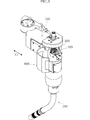
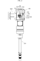
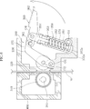
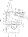
- FIG. 1 It is a whole perspective view showing an example of composition which attached a feeding device with a wire feeding mechanism concerning one embodiment attached to a welding torch. It is a front view of the structure shown in FIG. It is an enlarged front view which shows schematic structure of a wire feeding mechanism. It is the figure which represented typically a part of wire feeding mechanism as a cross section. It is a figure for demonstrating the operation procedure at the time of performing the maintenance of a wire feeding mechanism. It is a figure for demonstrating the operation procedure at the time of performing the maintenance of a wire feeding mechanism. It is a figure for demonstrating the operation procedure at the time of performing the maintenance of a wire feeding mechanism. It is a figure for demonstrating the operation procedure at the time of performing the maintenance of a wire feeding mechanism. It is a figure for demonstrating the operation procedure at the time of performing the maintenance of a wire feeding mechanism. It is a figure for demonstrating the operation procedure at the time of performing the maintenance of a wire feeding mechanism. It is a figure for demonstrating the operation procedure at the time of performing
- FIG. 1 is a perspective view showing a welding torch 200 including a feeding device 100 in which a wire feeding mechanism according to one embodiment is incorporated.
- FIG. 2 is a front view of the welding torch 200.
- the welding torch 200 is attached to the wrist of a manipulator configured as an articulated robot composed of a plurality of arms, and is used to perform automatic welding such as consumable electrode gas shield arc welding.
- a welding wire (hereinafter simply referred to as “wire”) is supplied to the welding torch 200 via a predetermined cable (for example, a conduit cable or a power cable).
- a power feed tip is provided inside the front end side of the welding torch 200.
- the wire is fed by the feeding device 100 toward the power feed tip in the welding torch 200 and then fed out from the opening at the tip of the welding torch 200.
- the welding torch 200 is supplied with electric power and shielding gas.
- the power is supplied from a power supply device via a power cable, and is supplied to the wire via a power supply chip.
- the shield gas is supplied from, for example, a gas cylinder, flows through the welding torch 200, and is ejected to the outside from the opening at the tip of the welding torch 200.
- the feeding device 100 is attached to the proximal end portion of the welding torch 200. As shown in FIGS. 2 and 3, the feeding device 100 includes a wire feeding mechanism 300, a frame 400 that supports the wire feeding mechanism 300, a wire guide 500, and a cover 600.
- the frame 400 is made of metal, for example.
- the frame 400 includes a bottom plate and side plates erected on the bottom plate, and a predetermined internal space is formed by these plate portions.
- the wire guide 500 is provided inside the frame 400.
- the wire guide 500 guides the wire W supplied via a cable (not shown). Specifically, a hole for inserting the wire W is formed in the wire guide 500. Accordingly, the wire guide 500 appropriately guides the wire W supplied via the cable to the outside of the feeding device 100.
- the wire W that has passed through the feeding device 100 passes through the inside of the welding torch 200 and is sent to the tip of the welding torch 200.
- the wire feeding mechanism 300 includes a feeding roll 310, a pressure roll 320, a pressure arm 330, a pressure mechanism 340, and a motor 380 (see FIG. 1). It is out.
- the feed roll 310, the pressure roll 320, the pressure arm 330, and the pressure mechanism 340 are supported by the frame 400 and are accommodated in the internal space of the frame. 1 and 2 show a state where the cover 600 is opened. When the cover 600 is closed, the feed roll 310, the pressure roll 320, the pressure arm 330, and the pressure mechanism 340 are covered by the cover 600.
- the supply roll 310 cooperates with the pressure roll 320 to send out the wire W in a desired direction.
- the feed roll 310 is fixed to the rotating shaft 381 of the motor 380.
- the shaft 381 extends parallel to the first direction X1 (see FIG. 1), and rotates around an axis parallel to the direction. As the shaft 381 rotates, the feed roll 310 also rotates around the same axis.
- a groove 312 for guiding the wire W is formed on the outer peripheral surface 311 of the feed roll 310.
- the groove 312 opens outward in the radial direction with respect to the axis of the shaft 381.
- the groove 312 is recessed inward from the outer peripheral surface 311 of the feed roll 310.
- the pressure roll 320 is arranged on the opposite side to the feed roll 310 with the wire W as a reference.
- the pressure roll 320 is rotatably supported by the pressure arm 330.
- the pressure arm 330 is supported by the frame 400 so as to be rotatable around the first axis O1.
- the pressure roll 320 is rotatable around the second axis O ⁇ b> 2 attached to the pressure arm 330.
- the first axis O1 and the second axis O2 each extend parallel to the first direction X1.
- the outer peripheral surface 321 of the pressure roll 320 faces radially outward with respect to the axis of the second axis O2.
- the outer peripheral surface 321 of the pressure roll 320 can be moved close to and away from the outer peripheral surface 311 of the feed roll 310.
- the feed roll 310 (and hence the pressure roll 320 as a driven roll) rotates with the wire W sandwiched between the outer peripheral surface 321 of the pressure roll 320 and the groove 312 of the feed roll 310.
- the wire W is fed.
- a groove may be formed on the outer peripheral surface of the pressure roll 320, and the wire W may be sandwiched between the groove and the groove 312 of the feed roll 310.
- the rotation direction of the pressure roll 320 and the rotation direction of the feed roll 310 are opposite to each other.
- a frictional force acts on the wire W from the feed roll 310 and the wire W is fed.
- the wire W is fed downward in FIG.
- the pressure arm 330 is rotatably supported by the frame 400 via the first axis O1.
- the first axis O ⁇ b> 1 is located on the proximal end side of the pressure arm 330.
- a force receiving portion 331 is provided on the distal end side of the pressure arm 330.
- the force receiving portion 331 is a portion that receives a force from the pressurizing mechanism 340 by a pressing force portion 361 of the pressurizing mechanism 340 (second structure portion 360) described later.
- the pressing force portion 361 has a groove shape.
- the second arm O2 that supports the pressure roll 320 is attached to the pressure arm 330.
- the second axis O2 is located between the first axis O1 of the pressure arm 330 and the force receiving portion 331, and is located closer to the first axis O1 than the force receiving portion 331.
- the pressure mechanism 340 (see FIGS. 3 and 4) is for generating a force from the pressure roll 320 toward the feed roll 310 by driving the pressure arm 330.
- the pressurizing mechanism 340 includes a first structure portion 350 and a second structure portion 360 supported by the first structure portion 350.
- the first structure part 350 includes a case 351, a shaft 352, a nut 353, and a joint 354.
- the shaft 352 is provided inside the case 351 and is movable in the axial direction (longitudinal direction) of the case 351.
- a locking portion 352 a is provided at the base end of the shaft 352, and a locked portion 351 a is provided at the base end of the case 351.
- the locking portion 352a has a flange shape that protrudes at right angles to the longitudinal direction of the shaft 352. As shown in FIGS. 5 and 6 and the like, the movement of the shaft 352 toward the distal end side of the case 351 is restricted by the locking portion 352a being locked to the locked portion 351a.
- a biasing member 370 is fitted on the shaft 352.
- the urging member 370 is a coil spring that is compressed with respect to the natural length.
- a screw part is formed on the tip side of the shaft 352, and the nut 353 is screwed into the screw part.
- the main part of the nut 353 is disposed inside the case 351.
- the nut 353 cannot rotate with respect to the case 351 but can move in the axial direction.
- the joint 354 is fixed to the tip of the shaft 352. As understood from FIGS. 4, 5, etc., the joint 354 and the shaft 352 can move in the axial direction with a predetermined stroke. As will be described later (see FIG. 8), when the joint 354 is rotated using the operation portion 362 of the second structure portion 360, the shaft 352 rotates accordingly. Both ends of the biasing member 370 are in contact with the nut 353 and the locked portion 351a of the case 351, respectively.
- the case 351 (first structure portion 350) is rotatably supported by the frame 400. Specifically, the case 351 rotates around the third axis O3.
- the third axis O3 is located at the base end of the case 351 (first structure 350) and extends in parallel with the first direction X1.
- the third axis O3 is located on the opposite side of the feed roll 310 with respect to the wire W.
- the third axis O3 is located farther from the wire W than the first axis O1.
- the second structure part 360 has a long shape as a whole, and includes a pressing force part 361 and an operation part 362.
- the pressing force portion 361 is provided at one end portion (“first end portion”) of the second structure portion 360, and the operation portion 362 is provided at the other end portion (“second end portion”). Yes.
- the pressing force portion 361 is a pin and can be engaged with the force receiving portion 331 of the pressure arm 330 (see FIGS. 4 and 5).
- the second structure part 360 is rotatably supported by the first structure part 350. Specifically, the second structure 360 rotates around the fourth axis O4.
- the fourth axis O4 is located closer to the first end of the second structure part 360 and extends in parallel with the first direction X1. In the present embodiment, the fourth axis O4 is located at the joint 354 of the first structure portion 350, that is, at the tip of the first structure portion 350.
- the operation unit 362 extends on the side opposite to the pressing force unit 361 with respect to the fourth axis O4.
- the distance from the third axis O3 to the fourth axis O4 is larger than the distance from the fourth axis O4 to the pressing force portion 361.
- the motor 380 (see FIG. 1) is for rotating the feed roll 310.
- the motor 380 is fixed to the proximal end portion of the welding torch 200.
- a feed roll 310 is fitted on the shaft 381 of the motor 380.
- grooves are formed in the outer peripheral surface of the shaft 381 and the inner peripheral surface of the feed roll 310, and a common key material 390 is fitted in these grooves. In this way, the feed roll 310 is directly fixed to the shaft 381 of the motor 380.
- the pressurizing arm 330 is rotatable around the first axis O1, and a force receiving portion 331 is provided at the tip.
- the urging member 370 compression coil spring
- the posture extends substantially parallel to the feeding direction.
- the force receiving portion 331 receives force from the urging member 370 (pressure mechanism 340) in a direction (upward in FIG. 4) that is substantially parallel to the wire W feeding direction. According to such a configuration, the entire pressure mechanism 340 can be disposed close to the wire W. This contributes to the miniaturization of the wire feeding mechanism 300.
- the pressure roll 320 is attached to the second axis O2, and the second axis O2 is closer to the first axis O1 than the force receiving portion 331 of the pressure arm 330. According to such a configuration, the pressure roll 320 can be appropriately pressed against the feed roll 310 by the force received by the force receiving portion 331 from the pressure mechanism 340. This contributes to the miniaturization of the wire feeding mechanism 300.
- FIG. 5 to FIG. 9 show operation procedures when performing maintenance such as replacement of the pressure roll 320 and the feed roll 310.
- the pressurizing mechanism 340 includes the first structure portion 350 and the second structure portion 360.
- the first structure portion 350 is rotatable around the third axis O3, and an urging member 370 is provided inside.
- the second structure part 360 is supported so as to be rotatable around the fourth axis O4 with respect to the first structure part 350, and has a pressing force part 361 for applying a force to the force receiving part 331 of the pressure arm 330.
- the transmission of the urging force by the urging member 370 can be blocked by rotating the second structure portion 360 in the direction of the arrow in the figure. .
- the distance from the third axis O3 to the fourth axis O4 is larger than the distance from the fourth axis O4 to the pressing force portion 361.
- the second structure portion 360 includes an operation portion 362 that extends to the opposite side of the pressing force portion 361 with respect to the fourth axis O4. According to such a configuration, the expansion / contraction stroke of the urging member 370 provided in the first structure portion 350 can be appropriately ensured, and the rotational operation force of the operation portion 362 is amplified to be applied to the pressing force portion 361. I can tell you. According to such a configuration, it is possible to easily perform an operation necessary to interrupt or transmit the force of the pressurizing mechanism 340.
- FIG. 6 shows a state in which the operation unit 362 (second structure unit 360) is further rotated in the arrow direction from the state shown in FIG.
- the pressure arm 330 rotates in the direction away from the wire W around the first axis O ⁇ b> 1 (clockwise), and the pressure roll 320 is moved to the wire. Leave W.
- FIG. 7 when the second structure portion 360 is further rotated in the direction of the arrow, the pressing force portion 361 is separated from the force receiving portion 331. Then, as shown in FIG. 8, the second structure portion 360 is completely separated from the pressurizing arm 330 by rotating the first structure portion 350 around the third axis O3 (clockwise). Can do.
- FIG. 7 shows a state in which the operation unit 362 (second structure unit 360) is further rotated in the arrow direction from the state shown in FIG.
- the pressure arm 330 rotates in the direction away from the wire W around the first axis O ⁇ b> 1 (clockwise), and the pressure roll 320 is moved to the wire. Leave
- the joint 354 rotates together with the second structure portion 360, and the nut 353 moves along the axial direction of the shaft 352. .
- the entire length (compression length) of the biasing member 370 changes.
- the elastic restoring force of the urging member 370 increases.
- the shaft 352 and the joint 354 are in the base end side of the case 351 along the axial direction.
- the urging member 370 is further compressed by a predetermined length.
- the force received by the force receiving portion 331 increases.
- the magnitude of the force received by the force receiving portion 331 from the pressurizing mechanism 340 can be adjusted.
- the force received by the force receiving portion 331 can be adjusted by a simple operation such as rotating the second structure portion 360.
- a force adjustment mechanism is realized by a configuration including the shaft 352, the nut 353, and the joint 354.
- a scale may be provided on the case 351 along the direction in which the nut 353 moves. This scale makes it easy to grasp the amount of movement of the nut 353 and enables accurate adjustment of the applied pressure.
- the first structure 350 when exchanging the pressure roll 320 and the feed roll 310, the first structure 350 is rotated around the third axis O3 and the pressure arm 330 is moved around the first axis O1. Rotate further. In this way, the first structure portion 350 and the pressure arm 330 can be sufficiently separated from the wire W in the direction intersecting the first direction X1, so that a large work space for roll replacement or the like can be taken. it can.
Landscapes
- Engineering & Computer Science (AREA)
- Physics & Mathematics (AREA)
- Plasma & Fusion (AREA)
- Mechanical Engineering (AREA)
- Wire Processing (AREA)
- Unwinding Of Filamentary Materials (AREA)
Abstract
Description
200 溶接トーチ
300 ワイヤ送給機構
310 送給ロール
311 外周面
312 溝
320 加圧ロール
321 外周面
330 加圧アーム
331 受力部
340 加圧機構
350 第1構造部
351 ケース
351a 被係止部
352 シャフト
352a 係止部
353 ナット
354 ジョイント
360 第2構造部
361 押力部
362 操作部
370 付勢部材
380 モータ
381 (モータの)シャフト
390 キー材
400 フレーム
500 ワイヤガイド
600 カバー
O1 第1軸
O2 第2軸
O3 第3軸
O4 第4軸
W ワイヤ
X1 第1方向
Claims (8)
- 回転軸心周りに回転する送給ロールと、
上記送給ロールに対し変位可能な加圧ロールと、
互いに離間する第1端および第2端を有するとともに、上記加圧ロールを回転可能に支持する加圧アームと、
上記送給ロールと上記加圧ロールとの間にワイヤを挟んだ状態で上記加圧ロールから上記送給ロールに加圧力が付与されるように、上記加圧アームに係合する加圧機構と、を備えたワイヤ送給機構であって、
上記加圧アームは、上記第1端に位置し且つ上記回転軸心に平行な第1軸周りに回動可能であり、上記第2端には受力部が設けられており、
上記加圧ロールが上記送給ロールを加圧するとき、上記加圧機構は、上記ワイヤの送給方向と略平行である方向に上記受力部に力を付与する構成とされている、ワイヤ送給機構。 - 上記加圧ロールは、上記回転軸心に平行な第2軸周りに回転可能であり、上記第2軸は、上記受力部よりも上記第1軸に近い位置にある、請求項1に記載のワイヤ送給機構。
- 上記加圧機構は、第1構造部およびこの第1構造部に支持される第2構造部を含み、
上記第1構造部は、上記第1軸を基準として上記送給ロールと反対側に位置するとともに、上記回転軸心に平行な第3軸周りに回動可能であり、
上記第2構造部は、第4軸周りに回動可能に上記第1構造部に支持されるとともに、上記受力部に係合する押力部を有する、請求項1または2に記載のワイヤ送給機構。 - 上記第3軸から上記第4軸までの距離は、上記第4軸から上記押力部までの距離よりも大であり、
上記第2構造部は、上記第4軸を基準として上記押力部とは反対側に延びる操作部を有する、請求項3に記載のワイヤ送給機構。 - 上記加圧機構は、上記第1構造部に設けられた付勢部材を含み、
上記加圧ロールが上記送給ロールを加圧するとき、上記付勢部材は上記第4軸から上記押力部に向かう方向に付勢力を与える、請求項3または4に記載のワイヤ送給機構。 - 上記加圧機構が上記受力部に付与する前記力を調整する調整機構をさらに備える、請求項1ないし5のいずれかに記載のワイヤ送給機構。
- 回転シャフトを有するモータをさらに備えており、上記送給ロールは、上記回転シャフトに固定されている、請求項1ないし6のいずれかに記載のワイヤ送給機構。
- 上記押力部は、上記受力部に係合するピンである、請求項3ないし7のいずれかに記載のワイヤ送給機構。
Priority Applications (5)
| Application Number | Priority Date | Filing Date | Title |
|---|---|---|---|
| US15/541,818 US10668552B2 (en) | 2015-01-13 | 2016-01-06 | Wire feed mechanism |
| CN201680004769.8A CN107107243B (zh) | 2015-01-13 | 2016-01-06 | 焊丝进给机构 |
| EP16737257.2A EP3246123B1 (en) | 2015-01-13 | 2016-01-06 | Wire-advancing mechanism |
| JP2016569315A JP6668585B2 (ja) | 2015-01-13 | 2016-01-06 | ワイヤ送給機構 |
| KR1020177018587A KR102315757B1 (ko) | 2015-01-13 | 2016-01-06 | 와이어 송급 기구 |
Applications Claiming Priority (2)
| Application Number | Priority Date | Filing Date | Title |
|---|---|---|---|
| JP2015004182 | 2015-01-13 | ||
| JP2015-004182 | 2015-01-13 |
Publications (1)
| Publication Number | Publication Date |
|---|---|
| WO2016114186A1 true WO2016114186A1 (ja) | 2016-07-21 |
Family
ID=56405733
Family Applications (1)
| Application Number | Title | Priority Date | Filing Date |
|---|---|---|---|
| PCT/JP2016/050199 Ceased WO2016114186A1 (ja) | 2015-01-13 | 2016-01-06 | ワイヤ送給機構 |
Country Status (6)
| Country | Link |
|---|---|
| US (1) | US10668552B2 (ja) |
| EP (1) | EP3246123B1 (ja) |
| JP (1) | JP6668585B2 (ja) |
| KR (1) | KR102315757B1 (ja) |
| CN (1) | CN107107243B (ja) |
| WO (1) | WO2016114186A1 (ja) |
Cited By (3)
| Publication number | Priority date | Publication date | Assignee | Title |
|---|---|---|---|---|
| CN109570702A (zh) * | 2018-12-10 | 2019-04-05 | 欧地希机电(青岛)有限公司 | 一种气压式退丝防护机构及送丝机 |
| CN112340527A (zh) * | 2020-10-28 | 2021-02-09 | 国网山东省电力公司单县供电公司 | 一种用于电力施工的出线管理装置 |
| US20220380169A1 (en) * | 2021-05-28 | 2022-12-01 | Endo Robotics Co., Ltd. | Tubular member moving apparatus |
Families Citing this family (6)
| Publication number | Priority date | Publication date | Assignee | Title |
|---|---|---|---|---|
| JP6973891B2 (ja) * | 2018-04-18 | 2021-12-01 | 株式会社ダイヘン | ワイヤ送給装置 |
| JP7014487B2 (ja) * | 2018-04-23 | 2022-02-01 | 株式会社ダイヘン | ワイヤ送給装置 |
| JP6516275B1 (ja) * | 2018-07-04 | 2019-05-22 | 株式会社カネダ技研 | 綴じ具 |
| US11738403B2 (en) * | 2020-01-27 | 2023-08-29 | The Esab Group Inc. | Push pull torch |
| WO2022128891A1 (en) * | 2020-12-17 | 2022-06-23 | Fremco A/S | Cable installation apparatus comprising replaceable drive device |
| CN119347121B (zh) * | 2024-12-20 | 2025-04-11 | 洛阳航辉新材料有限公司 | 一种钛合金壳体组合激光焊接装置 |
Citations (4)
| Publication number | Priority date | Publication date | Assignee | Title |
|---|---|---|---|---|
| JPS58119971U (ja) * | 1982-02-10 | 1983-08-16 | 大阪電気株式会社 | ワイヤ送給装置 |
| JPH0629772U (ja) * | 1992-09-16 | 1994-04-19 | 株式会社ダイヘン | 溶接ワイヤ送給装置 |
| US20050016976A1 (en) * | 2003-07-22 | 2005-01-27 | Lincoln Global, Inc., A Delware Corporation | Wire gripper for a drive unit of a wire feeder |
| US20120160897A1 (en) * | 2010-12-23 | 2012-06-28 | Lincoln Global, Inc. | Wire feeder wire drive design |
Family Cites Families (11)
| Publication number | Priority date | Publication date | Assignee | Title |
|---|---|---|---|---|
| JPS58119971A (ja) | 1982-01-11 | 1983-07-16 | Hitachi Ltd | 貫流水車 |
| JP2506892Y2 (ja) * | 1991-05-24 | 1996-08-14 | 日本鋼管株式会社 | 溶接ワイヤ―送給装置 |
| JP2937861B2 (ja) * | 1996-04-16 | 1999-08-23 | 昭三郎 牧野 | 糸状物の走行に追従する回転体装置 |
| JPH10324458A (ja) * | 1997-05-27 | 1998-12-08 | Babcock Hitachi Kk | 溶接ワイヤ送給装置 |
| CN2365001Y (zh) * | 1999-02-08 | 2000-02-23 | 时代集团公司 | 气保焊送丝机 |
| JP2001287033A (ja) * | 2000-04-03 | 2001-10-16 | Fanuc Ltd | ワイヤ供給装置 |
| AT500654B1 (de) * | 2004-07-09 | 2007-01-15 | Fronius Int Gmbh | Einrichtung zum fördern eines schweissdrahts |
| JP5392750B2 (ja) | 2008-10-22 | 2014-01-22 | 株式会社ダイヘン | 溶接ワイヤ送給機及び溶接装置 |
| CN201881037U (zh) * | 2010-10-15 | 2011-06-29 | 北京宏孚瑞达科技有限公司 | 便携式送丝机构 |
| CN102075030B (zh) * | 2010-12-06 | 2012-10-24 | 郑美波 | 蜗轮蜗杆减速型送丝电机设备及其送丝装置和焊接系统 |
| CN202861595U (zh) * | 2012-10-08 | 2013-04-10 | 梁添贵 | 一种焊接机送丝机构 |
-
2016
- 2016-01-06 US US15/541,818 patent/US10668552B2/en active Active
- 2016-01-06 EP EP16737257.2A patent/EP3246123B1/en active Active
- 2016-01-06 KR KR1020177018587A patent/KR102315757B1/ko active Active
- 2016-01-06 WO PCT/JP2016/050199 patent/WO2016114186A1/ja not_active Ceased
- 2016-01-06 JP JP2016569315A patent/JP6668585B2/ja active Active
- 2016-01-06 CN CN201680004769.8A patent/CN107107243B/zh active Active
Patent Citations (4)
| Publication number | Priority date | Publication date | Assignee | Title |
|---|---|---|---|---|
| JPS58119971U (ja) * | 1982-02-10 | 1983-08-16 | 大阪電気株式会社 | ワイヤ送給装置 |
| JPH0629772U (ja) * | 1992-09-16 | 1994-04-19 | 株式会社ダイヘン | 溶接ワイヤ送給装置 |
| US20050016976A1 (en) * | 2003-07-22 | 2005-01-27 | Lincoln Global, Inc., A Delware Corporation | Wire gripper for a drive unit of a wire feeder |
| US20120160897A1 (en) * | 2010-12-23 | 2012-06-28 | Lincoln Global, Inc. | Wire feeder wire drive design |
Non-Patent Citations (1)
| Title |
|---|
| See also references of EP3246123A4 * |
Cited By (4)
| Publication number | Priority date | Publication date | Assignee | Title |
|---|---|---|---|---|
| CN109570702A (zh) * | 2018-12-10 | 2019-04-05 | 欧地希机电(青岛)有限公司 | 一种气压式退丝防护机构及送丝机 |
| CN109570702B (zh) * | 2018-12-10 | 2020-09-29 | 欧地希机电(青岛)有限公司 | 一种气压式退丝防护机构及送丝机 |
| CN112340527A (zh) * | 2020-10-28 | 2021-02-09 | 国网山东省电力公司单县供电公司 | 一种用于电力施工的出线管理装置 |
| US20220380169A1 (en) * | 2021-05-28 | 2022-12-01 | Endo Robotics Co., Ltd. | Tubular member moving apparatus |
Also Published As
| Publication number | Publication date |
|---|---|
| KR20170102258A (ko) | 2017-09-08 |
| US10668552B2 (en) | 2020-06-02 |
| US20180001413A1 (en) | 2018-01-04 |
| KR102315757B1 (ko) | 2021-10-20 |
| EP3246123A4 (en) | 2018-10-03 |
| CN107107243A (zh) | 2017-08-29 |
| CN107107243B (zh) | 2019-11-01 |
| EP3246123A1 (en) | 2017-11-22 |
| JP6668585B2 (ja) | 2020-03-18 |
| EP3246123B1 (en) | 2020-10-21 |
| JPWO2016114186A1 (ja) | 2017-10-19 |
Similar Documents
| Publication | Publication Date | Title |
|---|---|---|
| JP6668585B2 (ja) | ワイヤ送給機構 | |
| EP2478987B1 (en) | Wire electrode drive pressure adjustment system and method | |
| CN102458784B (zh) | 链锯 | |
| JP5667727B1 (ja) | 電動式ドリルを用いた直線往復運動装置 | |
| KR101911234B1 (ko) | 전동 클램핑 장치 | |
| CN101700597A (zh) | 辊子 | |
| CN104066553B (zh) | 电动夹紧设备 | |
| JP2012250278A (ja) | 曲げ装置 | |
| US11203081B2 (en) | Removal device of welding electrode tip | |
| JP6087166B2 (ja) | ワイヤ供給機構、ワイヤ送給装置、およびアークシステム | |
| JP4454674B2 (ja) | ねじ締付装置 | |
| JP6643880B2 (ja) | ワーク把持装置 | |
| JP6156105B2 (ja) | 電動ドライバ装置 | |
| CN118789023A (zh) | 一种高效机房管道构件切割装置 | |
| JP3209159U (ja) | ポータブルスポット溶接ガン | |
| JP6030336B2 (ja) | 手動圧着工具 | |
| JP2018525236A (ja) | 工具への部品のクランプ装置 | |
| JP2018202434A (ja) | ワイヤ送給装置 | |
| JP5468672B1 (ja) | 高圧引下線くせ直し工具 | |
| JP2010091101A (ja) | 農機用コントロールケーブルの長さ調節装置 | |
| JP2008264108A (ja) | 内視鏡の湾曲操作装置 | |
| JP2021115594A5 (ja) | ||
| JP7609649B2 (ja) | ワイヤ送り出し装置およびこれを備えた溶接システム | |
| JP5162349B2 (ja) | 抵抗溶接ガン | |
| JP2008012596A (ja) | 把持装置 |
Legal Events
| Date | Code | Title | Description |
|---|---|---|---|
| 121 | Ep: the epo has been informed by wipo that ep was designated in this application |
Ref document number: 16737257 Country of ref document: EP Kind code of ref document: A1 |
|
| ENP | Entry into the national phase |
Ref document number: 2016569315 Country of ref document: JP Kind code of ref document: A |
|
| ENP | Entry into the national phase |
Ref document number: 20177018587 Country of ref document: KR Kind code of ref document: A |
|
| REEP | Request for entry into the european phase |
Ref document number: 2016737257 Country of ref document: EP |
|
| WWE | Wipo information: entry into national phase |
Ref document number: 15541818 Country of ref document: US |
|
| NENP | Non-entry into the national phase |
Ref country code: DE |