WO2016114306A1 - ブタジエン製造システム及びブタジエンの製造方法 - Google Patents
ブタジエン製造システム及びブタジエンの製造方法 Download PDFInfo
- Publication number
- WO2016114306A1 WO2016114306A1 PCT/JP2016/050844 JP2016050844W WO2016114306A1 WO 2016114306 A1 WO2016114306 A1 WO 2016114306A1 JP 2016050844 W JP2016050844 W JP 2016050844W WO 2016114306 A1 WO2016114306 A1 WO 2016114306A1
- Authority
- WO
- WIPO (PCT)
- Prior art keywords
- butadiene
- ethanol
- catalyst
- hydrogen
- mixed gas
- Prior art date
- Legal status (The legal status is an assumption and is not a legal conclusion. Google has not performed a legal analysis and makes no representation as to the accuracy of the status listed.)
- Ceased
Links
Images

Classifications
-
- C—CHEMISTRY; METALLURGY
- C07—ORGANIC CHEMISTRY
- C07C—ACYCLIC OR CARBOCYCLIC COMPOUNDS
- C07C1/00—Preparation of hydrocarbons from one or more compounds, none of them being a hydrocarbon
- C07C1/20—Preparation of hydrocarbons from one or more compounds, none of them being a hydrocarbon starting from organic compounds containing only oxygen atoms as heteroatoms
-
- B—PERFORMING OPERATIONS; TRANSPORTING
- B01—PHYSICAL OR CHEMICAL PROCESSES OR APPARATUS IN GENERAL
- B01J—CHEMICAL OR PHYSICAL PROCESSES, e.g. CATALYSIS OR COLLOID CHEMISTRY; THEIR RELEVANT APPARATUS
- B01J23/00—Catalysts comprising metals or metal oxides or hydroxides, not provided for in group B01J21/00
- B01J23/16—Catalysts comprising metals or metal oxides or hydroxides, not provided for in group B01J21/00 of arsenic, antimony, bismuth, vanadium, niobium, tantalum, polonium, chromium, molybdenum, tungsten, manganese, technetium or rhenium
- B01J23/20—Vanadium, niobium or tantalum
-
- B—PERFORMING OPERATIONS; TRANSPORTING
- B01—PHYSICAL OR CHEMICAL PROCESSES OR APPARATUS IN GENERAL
- B01J—CHEMICAL OR PHYSICAL PROCESSES, e.g. CATALYSIS OR COLLOID CHEMISTRY; THEIR RELEVANT APPARATUS
- B01J23/00—Catalysts comprising metals or metal oxides or hydroxides, not provided for in group B01J21/00
- B01J23/38—Catalysts comprising metals or metal oxides or hydroxides, not provided for in group B01J21/00 of noble metals
- B01J23/40—Catalysts comprising metals or metal oxides or hydroxides, not provided for in group B01J21/00 of noble metals of the platinum group metals
- B01J23/46—Ruthenium, rhodium, osmium or iridium
-
- B—PERFORMING OPERATIONS; TRANSPORTING
- B01—PHYSICAL OR CHEMICAL PROCESSES OR APPARATUS IN GENERAL
- B01J—CHEMICAL OR PHYSICAL PROCESSES, e.g. CATALYSIS OR COLLOID CHEMISTRY; THEIR RELEVANT APPARATUS
- B01J23/00—Catalysts comprising metals or metal oxides or hydroxides, not provided for in group B01J21/00
- B01J23/38—Catalysts comprising metals or metal oxides or hydroxides, not provided for in group B01J21/00 of noble metals
- B01J23/40—Catalysts comprising metals or metal oxides or hydroxides, not provided for in group B01J21/00 of noble metals of the platinum group metals
- B01J23/46—Ruthenium, rhodium, osmium or iridium
- B01J23/464—Rhodium
-
- C—CHEMISTRY; METALLURGY
- C01—INORGANIC CHEMISTRY
- C01B—NON-METALLIC ELEMENTS; COMPOUNDS THEREOF; METALLOIDS OR COMPOUNDS THEREOF NOT COVERED BY SUBCLASS C01C
- C01B3/00—Hydrogen; Gaseous mixtures containing hydrogen; Separation of hydrogen from mixtures containing it; Purification of hydrogen; Reversible storage of hydrogen
- C01B3/02—Production of hydrogen; Production of gaseous mixtures containing hydrogen
- C01B3/32—Production of hydrogen; Production of gaseous mixtures containing hydrogen by reaction of gaseous or liquid organic compounds with gasifying agents, e.g. water, carbon dioxide or air
- C01B3/34—Production of hydrogen; Production of gaseous mixtures containing hydrogen by reaction of gaseous or liquid organic compounds with gasifying agents, e.g. water, carbon dioxide or air by reaction of hydrocarbons with gasifying agents
-
- C—CHEMISTRY; METALLURGY
- C01—INORGANIC CHEMISTRY
- C01B—NON-METALLIC ELEMENTS; COMPOUNDS THEREOF; METALLOIDS OR COMPOUNDS THEREOF NOT COVERED BY SUBCLASS C01C
- C01B3/00—Hydrogen; Gaseous mixtures containing hydrogen; Separation of hydrogen from mixtures containing it; Purification of hydrogen; Reversible storage of hydrogen
- C01B3/02—Production of hydrogen; Production of gaseous mixtures containing hydrogen
- C01B3/32—Production of hydrogen; Production of gaseous mixtures containing hydrogen by reaction of gaseous or liquid organic compounds with gasifying agents, e.g. water, carbon dioxide or air
- C01B3/34—Production of hydrogen; Production of gaseous mixtures containing hydrogen by reaction of gaseous or liquid organic compounds with gasifying agents, e.g. water, carbon dioxide or air by reaction of hydrocarbons with gasifying agents
- C01B3/38—Production of hydrogen; Production of gaseous mixtures containing hydrogen by reaction of gaseous or liquid organic compounds with gasifying agents, e.g. water, carbon dioxide or air by reaction of hydrocarbons with gasifying agents using catalysts
-
- C—CHEMISTRY; METALLURGY
- C07—ORGANIC CHEMISTRY
- C07B—GENERAL METHODS OF ORGANIC CHEMISTRY; APPARATUS THEREFOR
- C07B61/00—Other general methods
-
- C—CHEMISTRY; METALLURGY
- C07—ORGANIC CHEMISTRY
- C07C—ACYCLIC OR CARBOCYCLIC COMPOUNDS
- C07C11/00—Aliphatic unsaturated hydrocarbons
- C07C11/12—Alkadienes
- C07C11/16—Alkadienes with four carbon atoms
- C07C11/167—1, 3-Butadiene
-
- C—CHEMISTRY; METALLURGY
- C07—ORGANIC CHEMISTRY
- C07C—ACYCLIC OR CARBOCYCLIC COMPOUNDS
- C07C29/00—Preparation of compounds having hydroxy or O-metal groups bound to a carbon atom not belonging to a six-membered aromatic ring
- C07C29/15—Preparation of compounds having hydroxy or O-metal groups bound to a carbon atom not belonging to a six-membered aromatic ring by reduction of oxides of carbon exclusively
- C07C29/151—Preparation of compounds having hydroxy or O-metal groups bound to a carbon atom not belonging to a six-membered aromatic ring by reduction of oxides of carbon exclusively with hydrogen or hydrogen-containing gases
- C07C29/1516—Multisteps
- C07C29/1518—Multisteps one step being the formation of initial mixture of carbon oxides and hydrogen for synthesis
-
- C—CHEMISTRY; METALLURGY
- C10—PETROLEUM, GAS OR COKE INDUSTRIES; TECHNICAL GASES CONTAINING CARBON MONOXIDE; FUELS; LUBRICANTS; PEAT
- C10J—PRODUCTION OF PRODUCER GAS, WATER-GAS, SYNTHESIS GAS FROM SOLID CARBONACEOUS MATERIAL, OR MIXTURES CONTAINING THESE GASES; CARBURETTING AIR OR OTHER GASES
- C10J3/00—Production of combustible gases containing carbon monoxide from solid carbonaceous fuels
- C10J3/72—Other features
- C10J3/82—Gas withdrawal means
-
- C—CHEMISTRY; METALLURGY
- C10—PETROLEUM, GAS OR COKE INDUSTRIES; TECHNICAL GASES CONTAINING CARBON MONOXIDE; FUELS; LUBRICANTS; PEAT
- C10K—PURIFYING OR MODIFYING THE CHEMICAL COMPOSITION OF COMBUSTIBLE GASES CONTAINING CARBON MONOXIDE
- C10K3/00—Modifying the chemical composition of combustible gases containing carbon monoxide to produce an improved fuel, e.g. one of different calorific value, which may be free from carbon monoxide
-
- C—CHEMISTRY; METALLURGY
- C10—PETROLEUM, GAS OR COKE INDUSTRIES; TECHNICAL GASES CONTAINING CARBON MONOXIDE; FUELS; LUBRICANTS; PEAT
- C10K—PURIFYING OR MODIFYING THE CHEMICAL COMPOSITION OF COMBUSTIBLE GASES CONTAINING CARBON MONOXIDE
- C10K3/00—Modifying the chemical composition of combustible gases containing carbon monoxide to produce an improved fuel, e.g. one of different calorific value, which may be free from carbon monoxide
- C10K3/06—Modifying the chemical composition of combustible gases containing carbon monoxide to produce an improved fuel, e.g. one of different calorific value, which may be free from carbon monoxide by mixing with gases
-
- C—CHEMISTRY; METALLURGY
- C01—INORGANIC CHEMISTRY
- C01B—NON-METALLIC ELEMENTS; COMPOUNDS THEREOF; METALLOIDS OR COMPOUNDS THEREOF NOT COVERED BY SUBCLASS C01C
- C01B2203/00—Integrated processes for the production of hydrogen or synthesis gas
- C01B2203/02—Processes for making hydrogen or synthesis gas
- C01B2203/0205—Processes for making hydrogen or synthesis gas containing a reforming step
- C01B2203/0211—Processes for making hydrogen or synthesis gas containing a reforming step containing a non-catalytic reforming step
- C01B2203/0216—Processes for making hydrogen or synthesis gas containing a reforming step containing a non-catalytic reforming step containing a non-catalytic steam reforming step
-
- C—CHEMISTRY; METALLURGY
- C01—INORGANIC CHEMISTRY
- C01B—NON-METALLIC ELEMENTS; COMPOUNDS THEREOF; METALLOIDS OR COMPOUNDS THEREOF NOT COVERED BY SUBCLASS C01C
- C01B2203/00—Integrated processes for the production of hydrogen or synthesis gas
- C01B2203/06—Integration with other chemical processes
-
- C—CHEMISTRY; METALLURGY
- C10—PETROLEUM, GAS OR COKE INDUSTRIES; TECHNICAL GASES CONTAINING CARBON MONOXIDE; FUELS; LUBRICANTS; PEAT
- C10J—PRODUCTION OF PRODUCER GAS, WATER-GAS, SYNTHESIS GAS FROM SOLID CARBONACEOUS MATERIAL, OR MIXTURES CONTAINING THESE GASES; CARBURETTING AIR OR OTHER GASES
- C10J2300/00—Details of gasification processes
- C10J2300/09—Details of the feed, e.g. feeding of spent catalyst, inert gas or halogens
- C10J2300/0913—Carbonaceous raw material
- C10J2300/0946—Waste, e.g. MSW, tires, glass, tar sand, peat, paper, lignite, oil shale
-
- Y—GENERAL TAGGING OF NEW TECHNOLOGICAL DEVELOPMENTS; GENERAL TAGGING OF CROSS-SECTIONAL TECHNOLOGIES SPANNING OVER SEVERAL SECTIONS OF THE IPC; TECHNICAL SUBJECTS COVERED BY FORMER USPC CROSS-REFERENCE ART COLLECTIONS [XRACs] AND DIGESTS
- Y02—TECHNOLOGIES OR APPLICATIONS FOR MITIGATION OR ADAPTATION AGAINST CLIMATE CHANGE
- Y02E—REDUCTION OF GREENHOUSE GAS [GHG] EMISSIONS, RELATED TO ENERGY GENERATION, TRANSMISSION OR DISTRIBUTION
- Y02E50/00—Technologies for the production of fuel of non-fossil origin
- Y02E50/30—Fuel from waste, e.g. synthetic alcohol or diesel
-
- Y—GENERAL TAGGING OF NEW TECHNOLOGICAL DEVELOPMENTS; GENERAL TAGGING OF CROSS-SECTIONAL TECHNOLOGIES SPANNING OVER SEVERAL SECTIONS OF THE IPC; TECHNICAL SUBJECTS COVERED BY FORMER USPC CROSS-REFERENCE ART COLLECTIONS [XRACs] AND DIGESTS
- Y02—TECHNOLOGIES OR APPLICATIONS FOR MITIGATION OR ADAPTATION AGAINST CLIMATE CHANGE
- Y02P—CLIMATE CHANGE MITIGATION TECHNOLOGIES IN THE PRODUCTION OR PROCESSING OF GOODS
- Y02P20/00—Technologies relating to chemical industry
- Y02P20/50—Improvements relating to the production of bulk chemicals
- Y02P20/52—Improvements relating to the production of bulk chemicals using catalysts, e.g. selective catalysts
Definitions
- the present invention relates to a butadiene production system and a butadiene production method.
- This application claims priority based on Japanese Patent Application No. 2015-4460 filed in Japan on January 13, 2015, the contents of which are incorporated herein by reference.
- butadiene such as 1,3-butadiene is used as a raw material for styrene-butadiene rubber (SBR).
- SBR styrene-butadiene rubber
- butadiene is purified from a C4 fraction by-produced when ethylene is synthesized from petroleum.
- Patent Document 1 proposes a method for producing butadiene from ethanol using a catalyst.
- the yield is not sufficiently high industrially.
- An object of the present invention is to provide a butadiene production system and a butadiene production method capable of producing butadiene with high yield.
- a butadiene production system includes a gas preparation device that prepares a mixed gas containing hydrogen and carbon monoxide by heating a raw material, and a gas preparation device that is provided downstream of the gas preparation device.
- An ethanolization apparatus for obtaining ethanol by bringing a mixed gas containing carbon oxide into contact with the first catalyst, and a butadieneization apparatus for providing butadiene by bringing the ethanol into contact with the second catalyst, which is provided after the ethanolization apparatus.
- return means for returning hydrogen by-produced in the butadiene unit to the ethanol unit.
- a butadiene production system includes a gas preparation device for preparing a mixed gas containing hydrogen and carbon dioxide by heating a raw material, and a hydrogen preparation device provided at a subsequent stage of the gas preparation device.
- An ethanolizer that obtains ethanol by bringing a mixed gas containing carbon dioxide into contact with a third catalyst, and a butadieneator that is provided downstream of the ethanolator and obtains butadiene by bringing the ethanol into contact with the second catalyst
- return means for returning hydrogen by-produced in the butadiene unit to the ethanol unit.
- the return means includes a pipe for connecting the butadiene apparatus and the ethanol apparatus.
- a method for producing butadiene according to an embodiment of the present invention includes a gas preparation step of preparing a mixed gas containing hydrogen and carbon monoxide by heating a raw material, and contacting the mixed gas with a first catalyst to obtain ethanol.
- a method for producing butadiene includes a gas preparation step in which a raw material is heated to prepare a mixed gas containing hydrogen and carbon dioxide, and the mixed gas is brought into contact with a third catalyst to produce ethanol.
- An ethanolification step to be obtained a butadiene step for obtaining butadiene by bringing the ethanol into contact with a second catalyst, and a return step for returning hydrogen by-produced in the butadieneization step to the ethanolization step.
- butadiene in the butadiene production system of the present invention, butadiene can be produced with high yield. According to the method for producing butadiene of the present invention, butadiene can be produced with high yield.
- “Returning hydrogen to the ethanolator” includes a mode in which the hydrogen returned by the equilibrium reaction represented by CO 2 + H 2 ⁇ CO + H 2 O is returned to the portion where it is not consumed in the previous stage of the ethanolizer.
- the temperature of the mixed gas in the pipe connected to the gas preparation device and the ethanolification device is lower than the temperature (eg, 1000 to 1200 ° C.) at which the equilibrium reaction is close to carbon monoxide (eg, 200 to 800 ° C.).
- a mode in which hydrogen is returned to the part marked with) is also included.
- “Returning hydrogen to the ethanolification step” means that the temperature of the mixed gas in the previous stage of the ethanolization step is lower than the temperature at which the equilibrium reaction is close to carbon monoxide (for example, the temperature of the mixed gas). In the range of 200 to 800 ° C.).
- “Raw material” is an organic substance that can be obtained by heating to produce a mixed gas containing hydrogen and carbon monoxide. Both raw material solids such as biomass and organic waste, and raw gas such as natural gas and waste gas are used. including.
- the "H 2 / CO ratio of hydrogen to carbon monoxide is supplied in ethanol step", a state where combined and mixed gas delivered from the gas preparation step in ethanol process, the hydrogen is returned to the ethanol step by returning step
- CO conversion means the percentage of the number of moles of carbon monoxide in the mixed gas occupied by the number of moles of carbon monoxide consumed in the reaction.
- Selectivity means the percentage of the number of moles of carbon monoxide consumed in the gas mixture that is occupied by the number of moles of carbon monoxide converted to a specific compound.
- the butadiene production system of the present invention is a system for producing a butadiene from the ethanol after the raw material is heated to prepare a mixed gas containing hydrogen and carbon monoxide, ethanol is obtained from the mixed gas.
- a mixed gas containing hydrogen and carbon monoxide ethanol is obtained from the mixed gas.
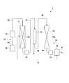
- the butadiene production system 1 of the present embodiment includes a gas preparation device 10, an ethanolization device 12 provided at a subsequent stage of the gas preparation device 10, and a purification provided at a subsequent stage of the ethanolization device 12.
- An apparatus 14, a butadiene conversion apparatus 16 provided at a subsequent stage of the purification apparatus 14, and a return means 18 for returning hydrogen from the butadiene conversion apparatus 16 to the ethanolization apparatus 12 are provided.
- the gas preparation device 10 includes a gasification furnace 20 and a reforming furnace 22 provided at the rear stage of the gasification furnace 20.
- the butadiene conversion apparatus 16 includes a reaction tube 24 and a gas-liquid separator 26 provided at the rear stage of the reaction tube 24.
- the gasification furnace 20 and the reforming furnace 22 are connected by a pipe 41.
- the reforming furnace 22 and the ethanolizer 12 are connected by a pipe 42.
- the ethanolizer 12 and the purifier 14 are connected by a pipe 43.
- a discharge pipe 44 is connected to the purification device 14.
- the purifier 14 and the reaction tube 24 of the butadiene unit 16 are connected by a pipe 45.
- the reaction tube 24 and the gas-liquid separator 26 are connected by a pipe 46.
- a pipe 47 is connected to the gas-liquid separator 26.
- the ethanolification apparatus 12 and the gas-liquid separator 26 of the butadiene conversion apparatus 16 are connected by a pipe provided in the return means 18.
- the gas preparation apparatus 10 is an apparatus for preparing a mixed gas containing hydrogen and carbon monoxide at an arbitrary ratio by heating a raw material, and includes a gasification furnace 20 and a reforming furnace 22.
- the gasification furnace 20 is a furnace that generates a mixed gas containing hydrogen and carbon monoxide by thermally decomposing raw materials such as biomass, organic waste (waste plastic, waste paper, waste clothing, etc.), coal, and the like. It is.
- a biomass or organic waste that can be pyrolyzed by burning a part thereof in the presence of oxygen to generate a mixed gas can be employed.
- a fluidized bed gasification type gasification furnace is preferable.
- the fluidized bed gasification type gasification furnace is preferable in that the influence of the raw material form is small and the amount of auxiliary fuel used is small.
- the reforming furnace 22 is a furnace that reforms hydrocarbons in a mixed gas into hydrogen and carbon monoxide by reacting with water.
- the concentration of carbon monoxide in the mixed gas generated in the gasification furnace 20 is increased, and the ratio of hydrogen to carbon monoxide is adjusted to a desired ratio.
- the H 2 / CO ratio of hydrogen and carbon monoxide is set to 1/2 to 4/1.
- a furnace made of a cylindrical body capable of heating the mixed gas at a temperature higher than the temperature for thermal decomposition in the gasification furnace 20 in the presence of water vapor can be employed.
- the piping 41 is preferably made of a material inert to the mixed gas, and examples thereof include stainless steel piping.
- a raw material solid is thermally decomposed in the gasification furnace 20 to generate a mixed gas containing hydrogen and carbon monoxide, and hydrocarbons in the mixed gas react with water in the reforming furnace 22. By doing so, it is reformed to a mixed gas having a higher carbon monoxide concentration.
- the piping 42 is preferably made of a material that is inert to the mixed gas, like the piping 41, and examples thereof include stainless steel piping.
- the pipe 42 is preferably provided with a gas purifier.
- a gas purifier By providing the gas purifier, impurities such as tar, sulfur, nitrogen, chlorine and moisture in the mixed gas are removed.
- the gas purifier for example, various types of gas purifiers known in the technical field such as a wet method and a dry method are employed.
- the wet method include sodium hydroxide method, ammonia absorption method, lime / gypsum method, magnesium hydroxide method and the like.
- the dry method include an adsorption method such as a pressure swing adsorption (PSA) method, an electron beam method, and the like.
- PSA pressure swing adsorption
- the pipe 42 may be provided with a cooler that lowers the temperature of the mixed gas. By providing the cooler, it becomes easy to sufficiently lower the temperature of the mixed gas supplied to the ethanolizer 12. Alternatively, the equilibrium gas transfer may be suppressed by quenching the mixed gas with a cooler, and the carbon monoxide may be maintained at a high concentration.
- the ethanolizer 12 is one in which the first catalyst is filled to form the reaction bed 12a.
- the ethanolizer 12 is preferably made of a material that is inert to the mixed gas or ethanol.
- the ethanolizer 12 preferably has a shape capable of withstanding heating of about 100 to 500 ° C. or pressurization up to about 10 MPa. Examples of the ethanolizer 12 include a substantially cylindrical member made of stainless steel.
- the reaction bed 12a may be a fixed bed, a moving bed, a fluidized bed, or the like.
- the mixed gas is supplied to the ethanolizer 12 in a gas state.
- a 1st catalyst is a catalyst for synthesize
- a well-known catalyst can be employ
- the catalyst metal used for the metal catalyst include a hydrogenation active metal or an aggregate of a hydrogenation active metal and a co-active metal described later.
- any metal conventionally known as a metal capable of synthesizing ethanol from a mixed gas may be used.
- alkali metals such as lithium and sodium; manganese and rhenium; Elements belonging to Group 8 of the periodic table such as ruthenium; Elements belonging to Group 9 of the periodic table such as cobalt and rhodium; Elements belonging to Group 10 of the periodic table such as nickel and palladium.
- These hydrogenation active metals may be used individually by 1 type, and may be used in combination of 2 or more type.
- Examples of the hydrogenation active metal include a combination of rhodium, manganese and lithium, a combination of ruthenium, rhenium and sodium, rhodium or ruthenium, from the point of further improving the CO conversion rate and improving the selectivity of ethanol.
- a combination of an alkali metal and another hydrogenation active metal is preferred.
- auxiliary metal examples include titanium, magnesium, vanadium and the like. Since the auxiliary metal is supported in addition to the hydrogenation active metal, the CO conversion rate and the selectivity of ethanol and acetaldehyde can be further increased.
- the metal catalyst is preferably a rhodium catalyst having a composition represented by the following formula (m1). aRh ⁇ bMn ⁇ cMe 1 ⁇ dMe 2 (m1)
- Me 1 is an alkali metal
- Me 2 is a promoter metal
- a, b, c and d are mole fractions
- a + b + c + d 1.
- a is preferably 0.053 to 0.98, more preferably 0.24 to 0.8, and still more preferably 0.32 to 0.67 from the viewpoint of easily increasing the CO conversion.
- b is preferably from 0.0006 to 0.67, more preferably from 0.033 to 0.57, and even more preferably from 0.089 to 0.44 from the viewpoint of easily increasing the CO conversion.
- c is preferably 0.00056 to 0.51, more preferably 0.026 to 0.42, and still more preferably 0.075 to 0.33 from the viewpoint of easily increasing the CO conversion.
- d may be 0 (that is, does not contain a promoter metal) or may be greater than 0 (that is, it contains a promoter metal). In the case of containing a co-active metal, d is preferably 0.0026 to 0.94, more preferably 0.02 to 0.48, and even more preferably 0.039 to 0.25 from the viewpoint of easily increasing the CO conversion. preferable.
- a rhodium catalyst and another metal catalyst other than the rhodium catalyst may be used in combination.
- the other metal catalyst include a catalyst in which copper alone or copper and a transition metal other than copper are supported on a carrier (hereinafter sometimes referred to as a copper-based catalyst).
- a copper-based catalyst a catalyst in which copper alone or copper and a transition metal other than copper are supported on a carrier.
- the copper catalyst those represented by the following formula (m2) are preferable.
- Me 3 is preferably zinc or chromium. Me 3 may be one type, or two or more types may be combined.
- e is preferably from 0.5 to 0.9, more preferably from 0.5 to 0.7, from the viewpoint of increasing the yield of ethanol.
- f is preferably from 0.1 to 0.5, more preferably from 0.3 to 0.5, from the viewpoint of increasing the yield of ethanol.
- the rhodium catalyst does not contain copper and the copper catalyst does not contain rhodium.
- a so-called supported catalyst in which a catalyst metal is supported on a porous carrier is preferable. If it is a supported catalyst, it is easy to control the ratio of ethanol and acetaldehyde in the product.
- the material of the porous carrier is not particularly limited, and examples thereof include silica, zirconia, titania, magnesia and the like. Among these, silica is preferable because various products having different specific surface areas and pore diameters can be procured on the market.
- the size of the porous carrier is not particularly limited.
- a silica porous carrier having a particle diameter of 0.5 to 5000 ⁇ m is preferable.
- the particle size of the porous carrier is adjusted by sieving.
- the porous carrier preferably has a narrowest particle size distribution.
- the total pore volume (total pore volume) in the porous carrier is not particularly limited, but is preferably 0.01 to 1.0 mL / g, more preferably 0.1 to 0.8 mL / g. If the total pore volume is not less than the above lower limit value, the specific surface area of the porous carrier is sufficiently large, the amount of the metal catalyst supported becomes sufficient, and it is easy to suppress the CO conversion rate from decreasing. If the total pore volume is less than or equal to the above upper limit value, the diffusion rate of the mixed gas does not become too high, and the contact time between the catalyst and the mixed gas becomes sufficient, so it is easy to suppress the decrease in the selectivity of ethanol. .
- the total pore volume is a value measured by a water titration method.
- the water titration method is a method in which water molecules are adsorbed on the surface of a porous carrier and the pore distribution is measured from the condensation of the molecules.
- the average pore diameter of the porous carrier is not particularly limited and is preferably 0.1 to 8 nm, more preferably 3 to 6 nm. If the average pore diameter is not less than the above lower limit value, the supported amount of the metal catalyst is sufficient, and it is easy to suppress a decrease in the CO conversion rate. If the average pore diameter is less than or equal to the above upper limit value, the diffusion rate of the mixed gas does not become too fast, and the contact time between the catalyst and the mixed gas becomes sufficient, so it is easy to suppress the decrease in the selectivity of ethanol. .
- the average pore diameter is a value measured by the following method.
- the average pore diameter is calculated from the total pore volume and the BET specific surface area.
- the average pore diameter is measured by a mercury porosimetry porosimeter.
- the total pore volume is a value measured by a water titration method
- the BET specific surface area is a value calculated from the amount of adsorption and the pressure at that time using nitrogen as an adsorption gas.
- mercury intrusion method mercury is pressurized and pressed into the pores of the porous carrier, and the average pore diameter is calculated from the pressure and the amount of mercury inserted.
- the specific surface area of the porous support is not particularly limited, but is preferably 1 ⁇ 1000m 2 / g, more preferably 10 ⁇ 800m 2 / g. If the specific surface area is not less than the above lower limit value, the amount of catalyst metal supported is sufficient, and the CO conversion rate is further increased. If the specific surface area is not more than the above upper limit value, the diffusion rate of the mixed gas becomes more appropriate, and the selectivity of ethanol is further increased.
- the specific surface area is a BET specific surface area measured by a BET gas adsorption method using nitrogen as an adsorption gas.
- the product of the total pore volume and the specific surface area of the porous carrier is preferably 1 ⁇ 1000mL ⁇ m 2 / g 2, more preferably 100 ⁇ 500mL ⁇ m 2 / g 2. If it is more than the said lower limit, the amount of catalyst metal supported will be sufficient, and the CO conversion will be further increased. If it is below the said upper limit, the diffusion rate of mixed gas becomes more suitable and the selectivity of ethanol increases more.
- the supporting state of the hydrogenation active metal and the co-active metal in the metal catalyst is not particularly limited.
- a powdered metal may be supported on the porous support, or may be supported on the porous support in the form of a metal element. It may be in a state that has been made. Of these, the state of being supported on a porous carrier in the form of a metal element is preferable. If it is in a state of being supported on the porous carrier in the form of a metal element, the contact area with the mixed gas becomes large, and the CO conversion rate and the selectivity of ethanol can be further increased.
- the amount of catalyst metal supported on the porous carrier is determined in consideration of the type and composition of the catalyst metal, the material of the porous carrier, etc., and is preferably 0.05 to 30 parts by mass with respect to 100 parts by mass of the porous carrier. 1 to 10 parts by mass is more preferable. If the loading amount is equal to or more than the above lower limit, the loading amount of the metal is sufficient, and it is easy to improve the CO conversion rate and ethanol selectivity. If the supported amount is less than or equal to the above upper limit value, the amount of co-active metal does not increase excessively, the hydrogenated active metal is easily made uniform and highly dispersed, and the CO conversion rate and ethanol selectivity are easily increased.
- the supported catalyst can be produced according to a conventionally known method for producing a supported catalyst.
- a conventionally known method for producing a supported catalyst For example, an impregnation method, an ion exchange method, etc. are mentioned, and an impregnation method is preferable.
- the metal catalyst obtained by using the impregnation method the metal is more uniformly dispersed and the contact efficiency with the mixed gas is further increased, so that the CO conversion rate and the selectivity of ethanol can be further increased.
- the pipe 43 includes the pressure control unit 28.
- the pressure control part 28 should just be what can make the pressure in the ethanol-ized apparatus 12 into arbitrary pressures, for example, a well-known pressure valve etc. are mentioned.
- the purifier 14 removes substances other than ethanol and acetaldehyde (for example, acetic acid, ethyl acetate, unreacted mixed gas, etc.) from the primary product.
- Examples of the purification apparatus 14 include an apparatus provided with a separation membrane.
- Examples of the separation membrane include a separation membrane for acid gas-containing gas treatment described in International Publication No. 2014/080670, and a porous support-zeolite membrane composite described in International Publication No. 2013/125661. It is done.
- the substance removed by the refining device 14 is discharged through the discharge pipe 44.
- the discharge pipe 44 is preferably made of a material that is inert with respect to the substance removed by the purification apparatus 14, and examples thereof include stainless steel pipes.
- the pipe 45 is preferably made of a material inert to ethanol and acetaldehyde, and examples thereof include a stainless steel pipe.
- the butadiene conversion apparatus 16 is an apparatus for obtaining butadiene by bringing ethanol into contact with a second catalyst.
- the butadiene unit 16 includes a reaction tube 24 that obtains butadiene by bringing ethanol into contact with a second catalyst, and a gas-liquid separator 26 that separates butadiene from the secondary product containing butadiene obtained in the reaction tube 24.
- the butadiene conversion apparatus 16 may further include a known device such as a gas flow rate control unit that adjusts a gas flow rate such as mass flow.
- the second catalyst is filled to form a reaction bed 24a.
- the reaction tube 24 is preferably made of a material inert to ethanol.
- the reaction tube 24 preferably has a shape capable of withstanding heating of about 100 to 500 ° C. or pressurization up to about 10 MPa.
- An example of the reaction tube 24 is a substantially cylindrical member made of stainless steel.
- the reaction bed 24a may be a fixed bed, a moving bed, a fluidized bed, or the like.
- the second catalyst only needs to be able to synthesize butadiene from ethanol.
- a catalyst containing a group 4-13 metal oxide and magnesium oxide in the periodic table can be cited.
- a catalyst obtained by joining a metal of Group 4 to 13 of the periodic table and magnesium oxide with one or more selected from magnesia and silica is preferable.
- the second catalyst is produced by a known method.
- a method for producing the second catalyst for example, there is a method in which a catalyst sol is obtained by dispersing a catalyst metal sol in a sol in which at least one selected from silica and magnesia is dispersed, and the catalyst sol is calcined. Can be mentioned.
- the piping 46 and the piping 47 are preferably made of a material inert to butadiene, and examples thereof include stainless steel piping.
- the pipe 46 includes the pressure control unit 30.
- the pressure control unit 30 may be anything that can make the pressure in the reaction tube 24 an arbitrary pressure, and examples thereof include a known pressure valve.
- the gas-liquid separator 26 may be a known gas-liquid separator made of a material inert to butadiene, hydrogen, or the like. In the gas-liquid separator 26, the butadiene is liquefied while the by-produced hydrogen is in a gaseous state, whereby the butadiene is gas-liquid separated. The separated and purified butadiene is collected in a storage tank or the like (not shown) through the pipe 47.
- the return means 18 is means for returning hydrogen by-produced in the butadiene unit 16 to the ethanol unit 12.
- the return means 18 includes a pipe that connects the gas-liquid separator 26 in the butadiene unit 16 and the ethanol unit 12.
- the piping of the return means 18 is preferably made of a material inert to hydrogen, and examples thereof include stainless steel piping.
- the piping of the return means 18 may be provided with a valve, a pump, a separation membrane, etc. as necessary.
- the position where the piping of the return means 18 in the ethanolizer 12 is connected is not particularly limited as long as the returned hydrogen is sufficiently consumed in the reaction bed 12a.
- the pipe of the return means 18 may be connected to the gas supply port (close to the reforming furnace 22) in the ethanolizer 12, may be connected to the center, or close to the discharge port (purification device 14). It may be connected to the side.
- the raw material solid is thermally decomposed in the gasification furnace 20 of the gas preparation device 10 to generate a mixed gas containing hydrogen and carbon monoxide.
- the mixed gas is sent to the reforming furnace 22 through the pipe 41, and the hydrocarbon in the mixed gas is reacted with water in the reforming furnace 22 to be reformed into a mixed gas having a higher carbon monoxide concentration. .
- the reformed mixed gas is sent from the reforming furnace 22 to the ethanolification device 12 through the pipe 42, reacts with the first catalyst, and becomes a gaseous primary product containing ethanol and acetaldehyde.
- the primary product is sent to the purifier 14 through the pipe 43 and purified.
- the purified primary product is sent to the reaction tube 24 of the butadiene unit 16 through the pipe 45. Ethanol in the gaseous primary product sent to the reaction tube 24 comes into contact with the second catalyst and reacts to become a gaseous secondary product containing butadiene and hydrogen.
- the secondary product is sent to the gas-liquid separator 26 through the pipe 46, and is gas-liquid separated into liquid butadiene and by-products containing gaseous hydrogen.
- Butadiene is recovered through the piping 47.
- the by-produced hydrogen is returned to the ethanolizer 12 by the return means 18.
- the method for producing butadiene of this embodiment includes the following gas preparation step, ethanolation step, butadieneization step, and return step.
- Gas preparation step A step of preparing a mixed gas containing hydrogen and carbon monoxide by heating a raw material.
- Ethanolization step a step of obtaining ethanol by bringing the mixed gas into contact with the first catalyst.
- Butadiation step a step of contacting the ethanol with a second catalyst to obtain butadiene.
- Returning step A step of returning hydrogen produced as a by-product in the butadiene conversion step to the gas preparation step.
- the gas preparation step of the present embodiment includes a gasification operation in which a raw material solid is thermally decomposed to generate a mixed gas containing hydrogen and carbon monoxide, and a hydrocarbon in the mixed gas is reacted with water to react with hydrogen. Reforming operation for reforming to carbon oxide.
- raw material solids such as pulverized biomass, organic waste (waste plastic, waste paper, waste clothing, etc.), coal, and the like in the gasification furnace 20 of the gas preparation device 10 are combined in the presence of oxygen. By burning the part, it is thermally decomposed and gasified to generate a mixed gas containing hydrogen and carbon monoxide.
- the temperature for thermal decomposition of the raw material solids in the gasification operation may be any temperature that generates a mixed gas containing hydrogen and carbon monoxide, preferably 200 to 1000 ° C., more preferably 500 to 800 ° C. . If the temperature for thermal decomposition is below the lower limit, the raw material solids are hardly gasified and serve no purpose. When the temperature for thermal decomposition exceeds the upper limit, the ratio of raw material solids to be combusted to increase the temperature increases, and the ratio of hydrogen and carbon monoxide in the mixed gas decreases.
- the hydrocarbon in the mixed gas supplied from the gasification furnace 20 through the pipe 41 is reacted with water to be reformed to hydrogen and carbon monoxide, and the carbon monoxide concentration is increased.
- the gas is reformed to a mixed gas in which hydrogen and carbon monoxide are in a desired ratio.
- the heating temperature of the mixed gas in the reforming operation is higher than the temperature for thermal decomposition in the gasification operation, preferably 800 to 2000 ° C, more preferably 1000 to 1500 ° C.
- the heating temperature is below the lower limit, the reaction does not proceed sufficiently and the carbon monoxide concentration does not increase.
- the heating temperature exceeds the upper limit value the material of the reforming furnace needs to have high heat resistance and the environmental load increases.
- the total ratio of hydrogen and carbon monoxide in the mixed gas prepared in the gas preparation step is preferably 50% by volume or more, more preferably 80% by volume or more, and still more preferably 90% by volume or more.
- the upper limit of the total ratio of hydrogen and carbon monoxide in the mixed gas prepared in the gas preparation step is 100% by volume.
- the mixed gas may contain methane, ethane, ethylene, nitrogen, carbon dioxide, water, etc. in addition to hydrogen and carbon monoxide.
- the mixed gas is supplied from the reforming furnace 22 in the gas preparation device 10 to the ethanolizer 12 through the pipe 42.
- the mixed gas supplied to the ethanolizer 12 comes into contact with the first catalyst, and a primary product containing ethanol and acetaldehyde is obtained.
- the primary product is gaseous.
- the total ratio of hydrogen and carbon monoxide to the total volume of the mixed gas supplied from the gas preparation step and the hydrogen returned by the return step is preferably 50% by volume or more, more preferably 80% by volume or more, 90 A volume% or more is more preferable.
- the upper limit of the total ratio of hydrogen and carbon monoxide is 100% by volume.
- the H 2 / CO ratio of hydrogen and carbon monoxide supplied to the ethanolization step is preferably 1/2 to 4/1, more preferably 1/1 to 3/1, and 1.5 / 1 to 2.5 / 1 is more preferable. If the H 2 / CO ratio is within the above range, it becomes easy to increase the synthesis efficiency of ethanol.
- reaction temperature The temperature at which the mixed gas and the first catalyst are brought into contact (reaction temperature), that is, the temperature of the reaction bed 12a is preferably 150 to 450 ° C, more preferably 200 to 400 ° C, and further preferably 250 to 350 ° C. If reaction temperature is more than the said lower limit, the speed
- the pressure (reaction pressure) at the time of bringing the mixed gas and the first catalyst into contact is preferably 0.5 to 10 MPa, more preferably 1 to 7.5 MPa, and more preferably 2 to 5 MPa. Further preferred. If the reaction pressure is equal to or higher than the lower limit, the rate of the catalytic reaction is sufficiently increased and ethanol can be produced more efficiently. If the reaction pressure is not more than the above upper limit, the ethanol selectivity can be increased.
- the space velocity of the gas in the reaction bed 12a (the value obtained by dividing the amount of gas supplied per unit time divided by the amount of catalyst (in terms of volume)) is preferably 10 to 100,000 L / L-catalyst / hr in terms of standard conditions, 50000 L / L-catalyst / hr is more preferable, and 3000 to 20000 L / L-catalyst / hr is more preferable.
- the space velocity is appropriately adjusted in consideration of the reaction pressure, the reaction temperature, and the composition of the mixed gas that is a raw material.
- the molar ratio represented by ethanol / acetaldehyde (hereinafter sometimes referred to as EtOH / AcH ratio) is preferably 1/5 to 5/1.
- EtOH / AcH ratio is within the above range, the yield of butadiene can be further increased.
- the EtOH / AcH ratio in the primary product is easily adjusted by a combination of the composition of the metal catalyst that is the first catalyst, the average pore diameter of the support of the metal catalyst, the reaction temperature, the reaction pressure, and the like. For example, increasing the reaction temperature increases the selectivity of ethanol and increases the EtOH / AcH ratio.
- the primary product containing ethanol obtained by the ethanolification apparatus 12 is sent to the purification apparatus 14 through the pipe 43 and purified to remove substances other than ethanol and acetaldehyde.
- the purified primary product is supplied to the butadiene unit 16 through the pipe 45.
- reaction temperature The temperature at which the primary product and the second catalyst are brought into contact (reaction temperature), that is, the temperature of the reaction bed 24a is preferably 300 to 500 ° C., more preferably 350 to 450 ° C. If reaction temperature is more than the said lower limit, the rate of a catalytic reaction will fully increase and butadiene can be manufactured more efficiently. If reaction temperature is below the said upper limit, it will be easy to suppress degradation of a 2nd catalyst.
- reaction pressure for bringing the primary product into contact with the second catalyst, that is, the pressure in the reaction tube 24 is, for example, normal pressure to 1 MPa.
- 70 mass% or more is preferable and, as for the ratio of the ethanol in the primary product supplied to a butadiene-ized process, 90 mass% or more is more preferable. If the ratio of ethanol is not less than the above lower limit, the synthesis efficiency of butadiene can be further increased.
- the space velocity of the primary product in the reaction bed 24a is preferably 100 to 50000 L / L-catalyst / hr, more preferably 200 to 10000 L / L-catalyst / hr, and 300 to 5000 L / L-catalyst / hr in terms of standard conditions. hr is more preferable.
- the space velocity is appropriately adjusted in consideration of the reaction pressure, the reaction temperature, and the composition of the primary product.
- the second product is sent from the reaction tube 24 through the pipe 46 to the gas-liquid separator 26, the temperature is lowered, and the product is separated into liquid butadiene and by-product gaseous hydrogen.
- Butadiene is collected in a storage tank or the like (not shown) through the pipe 47.
- Hydrogen produced as a by-product in the butadiene process is returned to the ethanol process.
- hydrogen gas-liquid separated from butadiene by the gas-liquid separator 26 is returned to the ethanolizer 12 by the return means 18.
- the hydrogen to be returned is separated from by-products other than hydrogen with a separation membrane or the like, if necessary.
- the return amount of hydrogen is preferably such that the H 2 / CO ratio of hydrogen and carbon monoxide after being combined with the mixed gas from the gas adjustment step is 1/2 to 4/1, and preferably 1/1 to 3 / An amount of 1 is more preferred. If the amount of hydrogen returned is equal to or higher than the lower limit, it becomes easy to produce butadiene in a high yield. If the amount of hydrogen returned is less than or equal to the above upper limit, the H 2 / CO ratio can be easily adjusted.
- the reaction efficiency is highest when the H 2 / CO ratio is 2/1.
- the H 2 / CO ratio in the mixed gas obtained by combusting and reforming raw materials such as organic waste is usually about 1/1, the amount of hydrogen tends to be insufficient in the ethanolization step.
- It is possible to increase the H 2 / CO ratio by adding a step such as performing a shift reaction (CO + H 2 O ⁇ CO 2 + H 2 ) using a catalyst such as iron oxide (Fe 3 O 4 ) or platinum.
- a step such as performing a shift reaction (CO + H 2 O ⁇ CO 2 + H 2 ) using a catalyst such as iron oxide (Fe 3 O 4 ) or platinum.
- the ratio of hydrogen in the ethanol process can be easily increased without supplying new hydrogen. be able to. Therefore, by easily adjusting the H 2 / CO ratio to a ratio suitable for the ethanolation reaction using the first catalyst, ethanol can be obtained efficiently, and the final butadiene yield is accordingly high. Become.
- the gas preparation device included in the butadiene production system of the first embodiment may be any device that can prepare a mixed gas containing hydrogen and carbon monoxide by heating the raw material.
- a reforming furnace is provided without a gasification furnace.
- a raw gas such as natural gas or waste gas from a factory is reformed, and a mixed gas containing hydrogen and carbon monoxide.
- a gas preparation device for preparing The gas preparation apparatus which consists of a gasification reforming furnace provided with the function of both a gasification furnace and a reforming furnace may be sufficient.
- the return means included in the butadiene production system of the first embodiment stores hydrogen obtained from the butadiene conversion apparatus or by-products containing hydrogen in a storage tank or the like, and supplies it to the ethanolification apparatus by various transportation means such as transportation by vehicles. It may be a means for returning. However, it is preferable that the return means is means for returning using piping from the point of low energy loss.
- the method for producing butadiene according to the first embodiment is not limited to the method using the butadiene production system 1 described above.
- the method for producing butadiene of the first embodiment may be a method in which the gas preparation step does not include a gasification operation but includes only a reforming operation. In the gas preparation step, a gasification operation and a reforming operation may be performed simultaneously.
- FIG. 2 is a schematic diagram showing the butadiene production system 2 of the present embodiment.
- the butadiene production system 2 includes a gas preparation device 10A, an ethanolization device 12A provided at the subsequent stage of the gas preparation device 10A, a purification device 14A provided at the subsequent stage of the ethanolization device 12A, and a subsequent stage of the purification device 14A.
- the gas preparation device 10A includes a gasification furnace 20A and a reforming furnace 22A provided at the rear stage of the gasification furnace 20A.
- the gasification furnace 20A and the reforming furnace 22A are connected by a pipe 41.
- the reforming furnace 22A and the ethanolizer 12A are connected by a pipe 42.
- the ethanolizer 12 ⁇ / b> A and the purifier 14 ⁇ / b> A are connected by a pipe 43.
- a discharge pipe 44 is connected to the purifier 14A.
- the purifier 14 ⁇ / b> A and the reaction tube 24 of the butadiene unit 16 are connected by a pipe 45.
- the gas preparation device 10A is a device for heating a raw material to prepare a mixed gas containing hydrogen and carbon dioxide at an arbitrary ratio, and includes a gasification furnace 20A and a reforming furnace 22A.
- the gasification furnace 20A is a furnace that thermally decomposes raw materials such as biomass, organic waste (waste plastic, waste paper, waste clothing, etc.), coal, etc., and generates a mixed gas containing hydrogen and carbon dioxide. is there. Examples of the gasification furnace 20A include the same ones as those described in the gasification furnace 20 of the first embodiment.
- the mixed gas obtained in the gasifier 20A includes carbon monoxide.
- the reforming furnace 22A is a furnace for reforming the mixed gas obtained in the gasification furnace 20A into a gas having a higher carbon dioxide concentration and higher hydrogen concentration.
- Examples of the reforming furnace 22A include a furnace that performs a shift reaction (CO + H 2 O ⁇ CO 2 + H 2 ) using a catalyst such as iron oxide (Fe 3 O 4 ) or platinum.
- the pipe 42 may be provided with a gas dispersion device that saturates the mixed gas with a liquid such as water by aeration or the like, and the liquid saturated with the mixed gas may be supplied to the ethanolizer 12A.
- the ethanolification device 12A is a device that obtains ethanol by bringing the mixed gas sent from the gas preparation device 10A into contact with a third catalyst.
- the third catalyst in the present embodiment, it employs a catalyst for the synthesis of ethanol from hydrogen and carbon dioxide, a microorganism to perform the ethanol fermentation carbon dioxide as a substrate (CO 2 assimilating bacterium) are preferred.
- CO 2 assimilating bacterium By bringing the mixed gas into contact with the third catalyst in the ethanolizer 12A, a primary product containing ethanol is obtained.
- Any ethanol generator 12A may be used as long as it can produce ethanol using ethanol fermentation by microorganisms.
- a known bioreactor can be employed.
- the bioreactor include a continuous stirred tank reactor, an immobilized cell reactor, a trickle bed reactor, a bubble column, a gas lift fermenter, a membrane reactor (such as a hollow fiber membrane bioreactor), and a static mixer.
- the material of the ethanolizer 12A is preferably a material inert to the mixed gas or ethanol.
- the CO 2 assimilating bacteria known microorganisms having the ability to perform ethanol fermentation using carbon dioxide as a substrate can be employed.
- the CO 2 assimilating bacteria for example, Muellera can be used.
- the third catalyst may be one type or two or more types.
- the pipe 43 may be provided with a pressure control unit that controls the pressure in the ethanolizer 12A.
- a pressure control unit that controls the pressure in the ethanolizer 12A.
- the purification apparatus 14A removes substances other than ethanol (for example, by-products, water, culture medium, unreacted mixed gas, catalyst, etc.) from the primary product and the like.
- Examples of the purification device 14A include a distillation device, a gas-liquid separator, a solid-liquid separator, and combinations thereof.
- the substance removed by the purification apparatus 14A is discharged through the discharge pipe 44.
- the discharge pipe 44 is preferably made of a material that is inert to the substance removed by the purification apparatus 14A, and examples thereof include stainless steel pipes.
- the pipe 45 is provided with a heating device 32 for heating and gasifying liquid ethanol.
- a heating device 32 for heating and gasifying liquid ethanol.
- ethanol is supplied to the butadiene-ized apparatus 16 in the gasified state.
- the heating device 32 may be any device as long as it can gasify ethanol by heating, and a known heating device can be adopted.
- the material of the heating device 32 is preferably a material inert to ethanol.
- the return means 18 of the present embodiment may supply the returned hydrogen into the reaction solution in the ethanolator 12A or supply it to the gas phase in the ethanolizer 12A.
- a gas dispersion device that saturates the returned hydrogen to a liquid such as water by aeration or the like may be provided in the piping of the return means 18, and the liquid saturated with hydrogen may be supplied to the ethanolizer 12A.
- the raw material solid is thermally decomposed in the gasification furnace 20A of the gas preparation device 10A, and a mixed gas containing hydrogen and carbon dioxide is generated.
- the mixed gas is sent to the reforming furnace 22A through the pipe 41 and reformed into a mixed gas having higher carbon dioxide concentration and hydrogen concentration.
- the mixed gas is sent from the reforming furnace 22A through the pipe 42 to the ethanolizer 12A, reacts in contact with the third catalyst, and becomes a liquid primary product containing ethanol.
- the primary product is sent to the purification apparatus 14A through the pipe 43 and purified.
- the purified primary product is sent to the reaction tube 24 of the butadiene unit 16 through the pipe 45 while being gasified by the heating device 32.
- Ethanol in the gaseous primary product sent to the reaction tube 24 comes into contact with the second catalyst and reacts to become a gaseous secondary product containing butadiene and hydrogen.
- the secondary product is sent to the gas-liquid separator 26 through the pipe 46 and is gas-liquid separated into liquid butadiene and gaseous hydrogen.
- Butadiene is recovered through the piping 47.
- the hydrogen produced as a by-product is returned by the return means 18 to the ethanolizer 12A.
- the method for producing butadiene of this embodiment includes the following gas preparation step, ethanolation step, butadieneization step, and return step.
- Gas preparation step A step of heating a raw material to prepare a mixed gas containing hydrogen and carbon dioxide.
- Ethanolization step a step of obtaining ethanol by bringing the mixed gas into contact with a third catalyst.
- Butadiation step a step of contacting the ethanol with a second catalyst to obtain butadiene.
- Returning step A step of returning hydrogen produced as a by-product in the butadiene conversion step to the gas preparation step.
- the gas preparation process of the present embodiment includes a gasification operation in which a raw material solid is thermally decomposed to generate a mixed gas containing hydrogen and carbon dioxide, and the mixed gas is reformed to a gas having a higher carbon dioxide concentration and hydrogen concentration. Reforming operation.
- the raw material solids are partially pyrolyzed by burning in the presence of oxygen to gasify, and a mixed gas containing hydrogen and carbon dioxide is generated.
- a shift reaction is performed on the mixed gas supplied from the gasification furnace 20A through the pipe 41 to reform the mixed gas having a higher carbon dioxide concentration and higher hydrogen concentration.
- the H 2 / CO 2 ratio in the mixed gas prepared in the gas preparation step of the present embodiment is preferably 1/2 to 5/1, more preferably 1/1 to 4/1, and 1.5 / 1 to 3 / 1 is more preferable.
- the H 2 / CO 2 ratio is within the above range, it becomes easy to increase the yield of ethanol.
- the mixed gas in a state where the temperature is lowered is supplied to the ethanolizer 12A through the pipe 42.
- a CO 2 -utilizing bacterium as a third catalyst is present in a reaction solution containing water, a medium, and the like, and is adjusted to an environment in which ethanol fermentation is possible by microorganisms.
- Mixed gas supplied to the ethanol apparatus 12A is in contact with CO 2 utilizing bacteria, primary product comprising ethanol is obtained by ethanol fermentation.
- the primary product is a mixture of liquid (ethanol, water, etc.) and gas (unreacted mixed gas, etc.).
- the total ratio of hydrogen and carbon dioxide to the total volume of the mixed gas supplied from the gas preparation step and the hydrogen returned by the return step is preferably 50% by volume or more, more preferably 80% by volume or more, and 90% by volume. % Or more is more preferable.
- the upper limit of the total ratio of hydrogen and carbon dioxide is 100% by volume.
- the H 2 / CO 2 ratio of hydrogen and carbon dioxide supplied to the ethanolization step is preferably 1/2 to 5/1, more preferably 1/1 to 4/1, and 1.5 / 1 to 3/1. Further preferred. When the H 2 / CO 2 ratio is within the above range, it becomes easy to increase the yield of ethanol.
- the temperature of the mixed gas supplied to the ethanolizer 12A is preferably lowered to 30 to 70 ° C, more preferably 50 to 60 ° C. If the temperature of the supplied mixed gas is within the above range, it is easy to suppress a decrease in the amount of microorganisms due to heat.
- the supply amount of the mixed gas to the ethanolizer 12A is preferably an amount in which hydrogen and carbon dioxide are saturated with a liquid such as water. If the supply amount of the mixed gas is within the above range, ethanol can be produced more efficiently.
- the reaction temperature in the ethanolizer 12A is preferably 50 to 65 ° C, more preferably 55 to 60 ° C. If the reaction temperature is within the above range, ethanol can be produced more efficiently.
- the pressure (reaction pressure) in the ethanolizer 12A is preferably 0 to 1 MPa, more preferably 0.2 to 0.8 MPa, and further preferably 0.4 to 0.6 MPa.
- reaction pressure is equal to or higher than the lower limit, hydrogen and carbon dioxide in the mixed gas are easily dissolved in the reaction solution, and ethanol can be produced more efficiently.
- reaction pressure exceeds the upper limit, high pressure resistance is required, and the environmental load increases.
- the primary product containing ethanol obtained by the ethanolification apparatus 12A is sent to the purification apparatus 14A through the pipe 43, and purified by distillation, gas-liquid separation, etc. to remove substances other than ethanol.
- the purified primary product is supplied to the butadiene unit 16 through the pipe 45 while being heated and gasified by the heating device 32.
- the butadiene conversion process of the present embodiment can be performed in the same manner as in the butadiene production system 1.
- Hydrogen produced as a by-product in the butadiene process is returned to the ethanol process.
- hydrogen gas-liquid separated from butadiene by the gas-liquid separator 26 is returned to the ethanolizer 12A by the return means 18.
- the hydrogen to be returned is separated from by-products other than hydrogen with a separation membrane or the like, if necessary.
- the hydrogen returned by the return means 18 may be supplied into the reaction solution in the ethanolizer 12A or may be supplied to the gas phase.
- the amount of hydrogen returned is preferably such that the H 2 / CO 2 ratio of hydrogen to carbon dioxide after being combined with the mixed gas from the gas adjustment step is 1/2 to 5/1, preferably 1/1 to 4 / An amount of 1 is more preferred. If the amount of hydrogen returned is equal to or higher than the lower limit, it becomes easy to produce butadiene in a high yield. If the amount of hydrogen returned is less than or equal to the above upper limit, the H 2 / CO 2 ratio can be easily adjusted.
- the ratio of hydrogen in the ethanolization process can be easily increased by returning hydrogen produced as a by-product in the butadiene process. Therefore, ethanol can be obtained more efficiently than when hydrogen is not returned, and as a result, butadiene can be obtained in a high yield.
- the butadiene production system of the second embodiment is not limited to the butadiene production system 2 described above.
- the butadiene production system of the second embodiment may return hydrogen from a gas-liquid separator in the butadiene conversion apparatus to a pipe in the previous stage of the ethanol conversion apparatus.
- the gas preparation device provided in the butadiene production system of the second embodiment may be any device that can prepare a mixed gas containing hydrogen and carbon dioxide by heating the raw material.
- a gasification furnace may be provided without a reforming furnace.
- a reforming furnace is provided without a gasification furnace, and in the reforming furnace, a raw material gas such as natural gas or waste gas from a factory is heated and reformed to contain hydrogen and carbon dioxide.
- a gas preparation device for preparing a mixed gas may be used.
- the gas preparation apparatus which consists of a gasification reforming furnace provided with the function of both a gasification furnace and a reforming furnace may be sufficient.
- the return means provided in the butadiene production system of the second embodiment stores hydrogen obtained from the butadiene conversion apparatus or by-products containing hydrogen in a storage tank or the like, and supplies it to the ethanolization apparatus by various transport means such as transportation by vehicles. It may be a means for returning. However, it is preferable that the return means is means for returning using piping from the point of low energy loss.
- the method for producing butadiene according to the second embodiment is not limited to the method using the butadiene production system 2 described above.
- the method for producing butadiene of the present invention may be a method in which the gas preparation step does not include the reforming operation and includes only the gasification operation, and the gas preparation step does not include the gasification operation and includes only the reforming operation. It may be a method. In the gas preparation step, a gasification operation and a reforming operation may be performed simultaneously.
- Butadiene was produced using the butadiene production system 1 illustrated in FIG. Specifically, a simulated waste modeled on industrial waste (76% combustible, 9% ash, 15% moisture, 4,000 kcal / kg heat) is gasified in the gasification furnace 20 and reformed. In 22 a mixed gas was obtained by a steam reforming reaction. 3 g / hr of hydrogen returned from the butadiene unit 16 was further mixed with the mixed gas, and a mixed gas of 650 NL / hr was supplied to the ethanolizer 12. In the ethanolizer 12, 158 g / hr of ethanol was obtained by a reaction using a rhodium catalyst.
- the reaction temperature in the ethanolizer 12 was 280 ° C., and the reaction pressure was 2 MPa.
- the primary product containing ethanol obtained by the ethanolizer 12 was purified by a distillation apparatus as the purifier 14 and sent to the butadiene unit 16 to obtain a secondary product containing butadiene.
- a tantalum catalyst was used as the second catalyst.
- the reaction temperature in the reaction tube 24 was 420 ° C., the reaction pressure was 0.1 MPa, and the supply amount of the mixed gas was 158 g / hr.
- butadiene 93 g / hr and hydrogen 3 g / hr were obtained from the butadiene unit 16. The yield of butadiene was 88%.
Landscapes
- Chemical & Material Sciences (AREA)
- Organic Chemistry (AREA)
- Engineering & Computer Science (AREA)
- Chemical Kinetics & Catalysis (AREA)
- Combustion & Propulsion (AREA)
- Materials Engineering (AREA)
- Oil, Petroleum & Natural Gas (AREA)
- General Health & Medical Sciences (AREA)
- Inorganic Chemistry (AREA)
- General Chemical & Material Sciences (AREA)
- Health & Medical Sciences (AREA)
- Organic Low-Molecular-Weight Compounds And Preparation Thereof (AREA)
- Low-Molecular Organic Synthesis Reactions Using Catalysts (AREA)
- Catalysts (AREA)
Abstract
Description
本願は、2015年1月13日に、日本に出願された特願2015-4460号に基づき優先権を主張し、その内容をここに援用する。
しかし、特許文献1のように触媒を用いてエタノールからブタジエンを得る方法では、工業的には収率が充分に高くない。
本発明のブタジエンの製造方法によれば、高い収率でブタジエンを製造できる。
「水素をエタノール化装置に返送する」とは、エタノール化装置の前段において、CO2+H2⇔CO+H2Oで表される平衡反応によって返送された水素が消費されない部分に返送する態様も含むものとする。例えば、ガス調製装置とエタノール化装置に接続された配管における、混合ガスの温度が、前記平衡反応が一酸化炭素寄りである温度(例えば1000~1200℃)よりも低い温度(例えば200~800℃)になっている部分に水素を返送する態様も含まれる。
「水素をエタノール化工程に返送する」とは、エタノール化工程の前段における、混合ガスの温度が、前記平衡反応が一酸化炭素寄りである温度よりも低くなっている段階(例えば混合ガスの温度が200~800℃の段階)に水素を返送する態様も含むものとする。
「原料」とは、加熱することで水素と一酸化炭素を含む混合ガスが得られる有機物であり、バイオマス、有機性廃棄物等の原料固形物と、天然ガス、廃ガス等の原料ガスの両方を含む。
「エタノール化工程に供給する水素と一酸化炭素のH2/CO比」とは、ガス調製工程からエタノール工程に送られる混合ガスと、返送工程によってエタノール化工程に返送される水素を合わせた状態における水素と一酸化炭素の比率を意味する。「エタノール化工程に供給する水素と一酸化炭素のH2/CO2比」についても同様である。
「CO転化率」とは、混合ガス中の一酸化炭素のモル数のうち、反応で消費された一酸化炭素のモル数が占める百分率を意味する。
「選択率」とは、混合ガス中の消費された一酸化炭素のモル数のうち、特定の化合物へ変換された一酸化炭素のモル数が占める百分率を意味する。
(ブタジエン製造システム)
本発明のブタジエン製造システムは、原料を加熱して水素と一酸化炭素とを含む混合ガスを調製し、該混合ガスからエタノールを得た後、該エタノールからブタジエンを製造するためのシステムである。以下、本発明のブタジエン製造システムの一例を示して説明する。
この例では、エタノール化装置12とブタジエン化装置16の気液分離器26とが、返送手段18が備える配管で接続されている。
ガス化炉20は、バイオマス、有機性廃棄物(廃プラスチック、廃紙、廃衣料等。)、石炭等の原料固形物を熱分解させて、水素と一酸化炭素を含む混合ガスを発生させる炉である。ガス化炉20としては、例えば、バイオマスや有機性廃棄物を酸素の存在下で一部を燃焼することにより熱分解して、混合ガスを生成できるものを採用できる。ガス化炉としては、流動床式ガス化方式のガス化炉が好ましい。流動床式ガス化方式のガス化炉は、原料の形態の影響が少なく、補助燃料の使用量が少ない点で好ましい。
改質炉22としては、例えば、水蒸気の存在下においてガス化炉20における熱分解のための温度よりも高い温度で混合ガスを加熱できる筒状体からなるものを採用できる。
ガス精製機としては、例えば、湿式法、乾式法等、当該技術分野で知られる各方式のガス精製機が採用される。湿式法としては、水酸化ナトリウム法、アンモニア吸収法、石灰・石膏法、水酸化マグネシウム法等が挙げられる。乾式法としては、圧力スイング吸着(PSA)法等の吸着法、電子ビーム法等が挙げられる。
エタノール化装置12は、混合ガスやエタノールに対して不活性な材料からなるものが好ましい。また、エタノール化装置12は、100~500℃程度の加熱、又は10MPa程度迄の加圧に耐え得る形状のものが好ましい。エタノール化装置12としては、例えば、ステンレス製の略円筒形の部材が挙げられる。
エタノール化装置12には、混合ガスはガスの状態のままで供給される。
金属触媒を用いて水素と一酸化炭素との混合ガスからエタノールを合成する場合は、通常、下式(1)~(5)の反応により、エタノールに加えてアセトアルデヒドや酢酸を含む一次生成物が得られる。
2H2+2CO→CH3COOH ・・・(1)
3H2+2CO→CH3CHO+H2O ・・・(2)
2H2+CH3COOH→C2H5OH+H2O ・・・(3)
H2+CH3CHO→C2H5OH ・・・(4)
4H2+2CO→C2H5OH+H2O ・・・(5)
これらの水素化活性金属は、1種を単独で使用してもよく、2種以上を組み合わせて使用してもよい。水素化活性金属としては、CO転化率のさらなる向上、エタノールの選択率が向上する点から、ロジウム、マンガン及びリチウムを組み合わせたものや、ルテニウム、レニウム及びナトリウムを組み合わせたもの等、ロジウム又はルテニウムとアルカリ金属とその他の水素化活性金属とを組み合わせたものが好ましい。
aRh・bMn・cMe1・dMe2 ・・・(m1)
式(m1)中、Me1はアルカリ金属であり、Me2は助活性金属であり、a、b、c及びdはモル分率であり、a+b+c+d=1である。
bは、CO転化率を高めやすい点から、0.0006~0.67が好ましく、0.033~0.57がより好ましく、0.089~0.44がさらに好ましい。
cは、CO転化率を高めやすい点から、0.00056~0.51が好ましく、0.026~0.42がより好ましく、0.075~0.33がさらに好ましい。
dは、0(すなわち、助活性金属を含有しない)でもよく、0超(すなわち、助活性金属を含有する)でもよい。助活性金属を含有する場合、dは、CO転化率を高めやすい点から、0.0026~0.94が好ましく、0.02~0.48がより好ましく、0.039~0.25がさらに好ましい。
eCu・fMe3 ・・・(m2)
ただし、式(m2)中、Me3は、銅以外の遷移金属であり、e及びfはモル分率であり、e+f=1である。
eは、エタノールの収率が高くなる点から、0.5~0.9が好ましく、0.5~0.7がより好ましい。
fは、エタノールの収率が高くなる点から、0.1~0.5が好ましく、0.3~0.5がより好ましい。
多孔質担体の材質は、特に限定されず、例えば、シリカ、ジルコニア、チタニア、マグネシア等が挙げられる。なかでも、比表面積や細孔直径が異なる種々の製品が市場で調達できることから、シリカが好ましい。
全細孔容積は、水滴定法により測定される値である。水滴定法とは、多孔質担体の表面に水分子を吸着させ、分子の凝縮から細孔分布を測定する方法である。
平均細孔直径は、以下の手法で測定される値である。平均細孔直径が0.1nm以上10nm未満の場合、平均細孔直径は、全細孔容積とBET比表面積とから算出される。平均細孔直径が10nm以上の場合、平均細孔直径は、水銀圧入法ポロシメーターにより測定される。
ここで、全細孔容積は、水滴定法により測定される値であり、BET比表面積は、窒素を吸着ガスとし、その吸着量とその時の圧力から算出される値である。
水銀圧入法は、水銀を加圧して多孔質担体の細孔に圧入させ、その圧力と圧入された水銀量から平均細孔直径を算出するものである。
比表面積は、窒素を吸着ガスとし、BET式ガス吸着法により測定されるBET比表面積である。
精製装置14としては、例えば、分離膜を備えた装置が挙げられる。分離膜としては、例えば、国際公開第2014/080670号に記載された酸性ガス含有ガス処理用分離膜、国際公開第2013/125661号に記載された多孔質支持体-ゼオライト膜複合体等が挙げられる。
反応床24aは、固定床、移動床、流動床等のいずれでもよい。
好ましい第2の触媒としては、タンタル酸化物がマグネシア及びシリカで接合されたもの(Ta2O5/MgO/SiO2(質量比=2/83/15)、国際公開第2013/125389号参照)等が挙げられる。
第2の触媒の製造方法としては、例えば、シリカ及びマグネシアから選ばれる1種以上が分散されたゾルに、触媒金属のゾルを分散して触媒ゾルを得て、該触媒ゾルを焼成する方法が挙げられる。
本実施形態においては、配管46は圧力制御部30を備える。圧力制御部30は、反応管24内の圧力を任意の圧力にできるものであればよく、例えば、公知の圧力弁等が挙げられる。
気液分離器26では、副生した水素が気体の状態で、ブタジエンが液化することで、ブタジエンが気液分離される。分離精製されたブタジエンは配管47を通じて貯留槽等(不図示)に回収される。
返送手段18の配管は、水素に対して不活性な材質が好ましく、例えば、ステンレス製の配管等が挙げられる。
返送手段18の配管には、必要に応じて、バルブ、ポンプ、分離膜等が設けられていてもよい。
改質された混合ガスは、改質炉22から配管42を通じてエタノール化装置12に送られ、第1の触媒と接触して反応し、エタノール及びアセトアルデヒドを含むガス状の一次生成物となる。一次生成物は配管43を通じて精製装置14に送られて精製される。精製された一次生成物は、配管45を通じてブタジエン化装置16の反応管24に送られる。
反応管24に送られたガス状の一次生成物中のエタノールは、第2の触媒と接触して反応し、ブタジエン及び水素を含むガス状の二次生成物となる。該二次生成物は配管46を通じて気液分離器26に送られ、液状のブタジエンとガス状の水素を含む副生物とに気液分離される。ブタジエンは配管47を通じて回収される。
副生した水素は返送手段18によりエタノール化装置12へと返送される。
以下、本発明のブタジエンの製造方法の一例として、前記したブタジエン製造システム1を用いる製造方法について説明する。本実施形態のブタジエンの製造方法は、下記のガス調製工程、エタノール化工程、ブタジエン化工程及び返送工程を有する。
ガス調製工程:原料を加熱して水素と一酸化炭素を含む混合ガスを調製する工程。
エタノール化工程:前記混合ガスを第1の触媒に接触させてエタノールを得る工程。
ブタジエン化工程:前記エタノールを第2の触媒に接触させてブタジエンを得る工程。
返送工程:前記ブタジエン化工程において副生した水素を前記ガス調製工程に返送する工程。
本実施形態のガス調製工程は、原料固形物を熱分解させて水素と一酸化炭素を含む混合ガスを発生させるガス化操作と、混合ガス中の炭化水素を水と反応させることにより水素と一酸化炭素に改質する改質操作とを含む。
ガス化操作では、ガス調製装置10におけるガス化炉20において、粉砕したバイオマス、有機性廃棄物(廃プラスチック、廃紙、廃衣料等。)、石炭等の原料固形物を酸素の存在下で一部を燃焼することにより熱分解させてガス化し、水素と一酸化炭素とを含む混合ガスを発生させる。
なお、混合ガスは、水素及び一酸化炭素の他に、メタン、エタン、エチレン、窒素、二酸化炭素、水等を含んでいてもよい。
ガス調製装置10における改質炉22から、配管42を通じて混合ガスをエタノール化装置12に供給する。エタノール化装置12に供給された混合ガスは第1の触媒と接触し、エタノール及びアセトアルデヒドを含む一次生成物が得られる。
本実施形態においては、第1の触媒として金属触媒を用いる場合、一次生成物はガス状である。
一次生成物におけるEtOH/AcH比は、第1の触媒である金属触媒の組成、金属触媒の担体の平均細孔直径、反応温度、反応圧力等の組み合わせにより、容易に調節される。例えば、反応温度を高めるとエタノールの選択率が高まり、EtOH/AcH比は大きくなる。
エタノールを含む一次生成物を、ブタジエン化装置16の反応管24に供給し、反応床24aの第2の触媒と接触させる。これにより、下式(6)の反応によりブタジエン及び水素を含む二次生成物が得られる。得られる二次生成物はガス状である。
2C2H5OH→C4H6+H2+2H2O ・・・(6)
また、第2の触媒を用いることで、エタノールとアセトアルデヒドからブタジエンを合成することもできる。
ブタジエン化工程で副生した水素をエタノール化工程に返送する。具体的には、気液分離器26でブタジエンと気液分離した水素を、返送手段18によりエタノール化装置12に返送する。返送する水素は、必要に応じて、分離膜等で水素以外の副生物から分離する。
エタノール化工程に水素が返送されることで、一酸化炭素と水素の比率を第1の触媒によるエタノール化反応に適した比率にすることが容易になるため、エタノールの合成効率が高まる。その結果、最終的なブタジエンの収率が高くなる。
第1実施形態のブタジエンの製造方法は、ガス調製工程がガス化操作を含まず、改質操作のみを含む方法であってもよい。ガス調製工程においてガス化操作と改質操作が同時に行われる方法であってもよい。
以下、本発明のブタジエン製造システム及びブタジエンの製造方法の第2実施形態について説明する。本実施形態のブタジエン製造システム及びブタジエンの製造方法は、原料を加熱して水素と二酸化炭素とを含む混合ガスを調製し、第3の触媒を用いて該混合ガスからエタノールを得た後、該エタノールからブタジエンを製造するものである。
図2は、本実施形態のブタジエン製造システム2を示した模式図である。図2における図1と同じ部分には同符号を付して説明を省略する。
ブタジエン製造システム2は、ガス調製装置10Aと、ガス調製装置10Aの後段に設けられたエタノール化装置12Aと、エタノール化装置12Aの後段に設けられた精製装置14Aと、精製装置14Aの後段に設けられたブタジエン化装置16と、ブタジエン化装置16からエタノール化装置12Aに水素を返送する返送手段18とを備えている。ガス調製装置10Aは、ガス化炉20Aと、ガス化炉20Aの後段に設けられた改質炉22Aとを備えている。
ガス化炉20Aは、バイオマス、有機性廃棄物(廃プラスチック、廃紙、廃衣料等。)、石炭等の原料固形物を熱分解させて、水素と二酸化炭素を含む混合ガスを発生させる炉である。ガス化炉20Aとしては、例えば、第1実施形態のガス化炉20で挙げたものと同様のものが挙げられる。ガス化炉20Aで得られる混合ガスには、一酸化炭素も含まれる。
エタノール化装置12Aにおいて混合ガスを第3の触媒に接触させることで、エタノールを含む一次生成物が得られる。
エタノール化装置12Aの材質としては、混合ガスやエタノールに対して不活性な材質が好ましい。
第3の触媒は、1種であってもよく、2種以上であってもよい。
加熱装置32は、エタノールを加熱してガス化できるものであればよく、公知の加熱装置を採用できる。加熱装置32の材質は、エタノールに対して不活性な材質が好ましい。
該混合ガスは、改質炉22Aから配管42を通じてエタノール化装置12Aに送られ、第3の触媒と接触して反応し、エタノールを含む液状の一次生成物となる。一次生成物は配管43を通じて精製装置14Aに送られて精製される。精製された一次生成物は、配管45を通じ、加熱装置32でガス化された状態でブタジエン化装置16の反応管24に送られる。
反応管24に送られたガス状の一次生成物中のエタノールは、第2の触媒と接触して反応し、ブタジエン及び水素を含むガス状の二次生成物となる。該二次生成物は配管46を通じて気液分離器26に送られ、液状のブタジエンとガス状の水素とに気液分離される。ブタジエンは配管47を通じて回収される。
副生した水素は返送手段18によりエタノール化装置12Aへと返送される。
以下、前記したブタジエン製造システム2を用いたブタジエンの製造方法について説明する。本実施形態のブタジエンの製造方法は、下記のガス調製工程、エタノール化工程、ブタジエン化工程及び返送工程を有する。
ガス調製工程:原料を加熱して水素と二酸化炭素を含む混合ガスを調製する工程。
エタノール化工程:前記混合ガスを第3の触媒に接触させてエタノールを得る工程。
ブタジエン化工程:前記エタノールを第2の触媒に接触させてブタジエンを得る工程。
返送工程:前記ブタジエン化工程において副生した水素を前記ガス調製工程に返送する工程。
本実施形態のガス調製工程は、原料固形物を熱分解させて水素と二酸化炭素を含む混合ガスを発生させるガス化操作と、混合ガスを二酸化炭素濃度及び水素濃度がより高いガスに改質する改質操作とを含む。
改質操作では、改質炉22Aにおいて、ガス化炉20Aから配管41を通じて供給された混合ガスに対してシフト反応を行って、二酸化炭素濃度及び水素濃度のより高い混合ガスへと改質する。
ガス調製装置10Aにおける改質炉22Aから、配管42を通じて、温度を降下させた状態の混合ガスをエタノール化装置12Aに供給する。エタノール化装置12Aにおいては、水、培地等を含む反応液中に第3の触媒であるCO2資化性菌が存在しており、微生物によりエタノール発酵が可能な環境に調整されている。エタノール化装置12Aに供給された混合ガスはCO2資化性菌と接触し、エタノール発酵によりエタノールを含む一次生成物が得られる。
本実施形態においては、一次生成物は液体(エタノール、水等。)とガス(未反応の混合ガス等。)の混合物である。
本実施形態のブタジエン化工程は、ブタジエン製造システム1の場合と同様に行える。
ブタジエン化工程で副生した水素をエタノール化工程に返送する。具体的には、気液分離器26でブタジエンと気液分離した水素を、返送手段18によりエタノール化装置12Aに返送する。返送する水素は、必要に応じて、分離膜等で水素以外の副生物から分離する。
返送手段18により返送した水素は、エタノール化装置12Aにおける反応液中に供給してもよく、気相に供給してもよい。
本実施形態のブタジエンの製造方法においては、第1実施形態と同様に、ブタジエン化工程で副生した水素を返送することでエタノール化工程における水素の比率を容易に高めることができる。そのため、水素を返送しない場合に比べてエタノールを効率的に得ることができ、その結果、高収率でブタジエンを得ることができる。
例えば、第2実施形態のブタジエン製造システムは、ブタジエン化装置における気液分離器からエタノール化装置の前段の配管に水素を返送するものであってもよい。
本発明のブタジエンの製造方法は、ガス調製工程が改質操作を含まず、ガス化操作のみを含む方法であってもよく、ガス調製工程がガス化操作を含まず、改質操作のみを含む方法であってもよい。ガス調製工程においてガス化操作と改質操作が同時に行われる方法であってもよい。
[成分分析]
各例において得られた二次生成物中のブタジエン、水素及びエチレンの量は、ガスクロマトグラフィーにより測定した。
図1に例示したブタジエン製造システム1を用いてブタジエンの製造を行った。
具体的には、産業廃棄物を模した模擬廃棄物(可燃分76%、灰分9%、水分15%、熱量4,000kcal/kg)400g/hrをガス化炉20でガス化し、改質炉22で水蒸気改質反応により、混合ガスを得た。該混合ガスにブタジエン化装置16から返送した水素3g/hrをさらに混合し、650NL/hrの混合ガスをエタノール化装置12に供給した。
エタノール化装置12においては、ロジウム系触媒を用いた反応により、158g/hrのエタノールを得た。エタノール化装置12における反応温度は280℃、反応圧力は2MPaとした。
エタノール化装置12で得たエタノールを含む一次生成物を、精製装置14である蒸留器により精製し、ブタジエン化装置16に送り、ブタジエンを含む二次生成物を得た。第2の触媒としては、タンタル系触媒を用いた。反応管24における反応温度は420℃、反応圧力は0.1MPa、混合ガスの供給量は158g/hrとした。
最終的に、ブタジエン化装置16からは、ブタジエン93g/hr、水素3g/hrを得た。ブタジエンの収率は88%であった。
ブタジエン化装置16で副生した水素をエタノール化装置12に返送しなかった以外は、実施例1と同様にしてブタジエンを製造した。改質炉22では615NL/hrの混合ガスが得られた。エタノール化装置12では145g/hrのエタノールが得られた。
最終的に、ブタジエン化装置16からは、ブタジエン85g/hr、水素3g/hrを得た。ブタジエンの収率は82%であった。
10、10A ガス調製装置
12、12A エタノール化装置
14、14A 精製装置
16 ブタジエン化装置
18 返送手段
20、20A ガス化炉
22、22A 改質炉
24 反応管
26 気液分離器
41~43、45~47 配管
44 排出管
Claims (5)
- 原料を加熱して水素と一酸化炭素を含む混合ガスを調製するガス調製装置と、
前記ガス調製装置の後段に設けられ、水素と一酸化炭素を含む混合ガスを第1の触媒に接触させてエタノールを得るエタノール化装置と、
前記エタノール化装置の後段に設けられ、前記エタノールを第2の触媒に接触させてブタジエンを得るブタジエン化装置と、
前記ブタジエン化装置において副生した水素を前記エタノール化装置に返送する返送手段と、を備える、ブタジエン製造システム。 - 原料を加熱して水素と二酸化炭素を含む混合ガスを調製するガス調製装置と、
前記ガス調製装置の後段に設けられ、水素と二酸化炭素を含む混合ガスを第3の触媒に接触させてエタノールを得るエタノール化装置と、
前記エタノール化装置の後段に設けられ、前記エタノールを第2の触媒に接触させてブタジエンを得るブタジエン化装置と、
前記ブタジエン化装置において副生した水素を前記エタノール化装置に返送する返送手段と、を備える、ブタジエン製造システム。 - 前記返送手段が、前記ブタジエン化装置と前記エタノール化装置とを接続する配管を備える、請求項1又は2に記載のブタジエン製造システム。
- 原料を加熱して水素と一酸化炭素を含む混合ガスを調製するガス調製工程と、
前記混合ガスを第1の触媒に接触させてエタノールを得るエタノール化工程と、
前記エタノールを第2の触媒に接触させてブタジエンを得るブタジエン化工程と、
前記ブタジエン化工程において副生した水素を前記エタノール化工程に返送する返送工程と、を有するブタジエンの製造方法。 - 原料を加熱して水素と二酸化炭素を含む混合ガスを調製するガス調製工程と、
前記混合ガスを第3の触媒に接触させてエタノールを得るエタノール化工程と、
前記エタノールを第2の触媒に接触させてブタジエンを得るブタジエン化工程と、
前記ブタジエン化工程において副生した水素を前記エタノール化工程に返送する返送工程と、を有するブタジエンの製造方法。
Priority Applications (4)
| Application Number | Priority Date | Filing Date | Title |
|---|---|---|---|
| JP2016569480A JP6774710B2 (ja) | 2015-01-13 | 2016-01-13 | ブタジエン製造装置及びブタジエンの製造方法 |
| US15/527,033 US10189754B2 (en) | 2015-01-13 | 2016-01-13 | Butadiene production system and butadiene production method |
| EP16737377.8A EP3246302A4 (en) | 2015-01-13 | 2016-01-13 | Butadiene production system and butadiene production method |
| CN201680004019.0A CN107001176A (zh) | 2015-01-13 | 2016-01-13 | 丁二烯制造系统及丁二烯的制造方法 |
Applications Claiming Priority (2)
| Application Number | Priority Date | Filing Date | Title |
|---|---|---|---|
| JP2015-004460 | 2015-01-13 | ||
| JP2015004460 | 2015-01-13 |
Publications (1)
| Publication Number | Publication Date |
|---|---|
| WO2016114306A1 true WO2016114306A1 (ja) | 2016-07-21 |
Family
ID=56405847
Family Applications (1)
| Application Number | Title | Priority Date | Filing Date |
|---|---|---|---|
| PCT/JP2016/050844 Ceased WO2016114306A1 (ja) | 2015-01-13 | 2016-01-13 | ブタジエン製造システム及びブタジエンの製造方法 |
Country Status (5)
| Country | Link |
|---|---|
| US (1) | US10189754B2 (ja) |
| EP (1) | EP3246302A4 (ja) |
| JP (1) | JP6774710B2 (ja) |
| CN (1) | CN107001176A (ja) |
| WO (1) | WO2016114306A1 (ja) |
Cited By (1)
| Publication number | Priority date | Publication date | Assignee | Title |
|---|---|---|---|---|
| JP2024546685A (ja) * | 2021-12-08 | 2024-12-26 | ブリヂストン アメリカズ タイヤ オペレーションズ、 エルエルシー | 使用済みタイヤからのブタジエン生成 |
Families Citing this family (1)
| Publication number | Priority date | Publication date | Assignee | Title |
|---|---|---|---|---|
| WO2023150129A1 (en) * | 2022-02-01 | 2023-08-10 | Cecilia Energy Inc. | Methods and apparatuses for producing hydrogen |
Citations (3)
| Publication number | Priority date | Publication date | Assignee | Title |
|---|---|---|---|---|
| JP2012217886A (ja) * | 2011-04-05 | 2012-11-12 | Mitsubishi Heavy Ind Ltd | エタノール合成触媒及びエタノール合成システム |
| JP2013121939A (ja) * | 2011-12-12 | 2013-06-20 | Ichikawa Office Inc | ブタジエンの製造方法 |
| WO2013125389A1 (ja) * | 2012-02-20 | 2013-08-29 | 株式会社ダイセル | 1,3-ブタジエンの製造方法 |
Family Cites Families (15)
| Publication number | Priority date | Publication date | Assignee | Title |
|---|---|---|---|---|
| JP2813770B2 (ja) | 1996-02-15 | 1998-10-22 | 通商産業省基礎産業局長 | エタノールの製造方法 |
| CN1724151A (zh) * | 2004-07-22 | 2006-01-25 | 中国科学院大连化学物理研究所 | 一种用于co加氢合成二碳含氧化合物的催化剂 |
| US8088832B2 (en) | 2006-04-05 | 2012-01-03 | Woodland Biofuels Inc. | System and method for converting biomass to ethanol via syngas |
| CN102333748B (zh) | 2009-02-12 | 2014-12-24 | 有限会社市川事务所 | 乙醇的制造方法 |
| JP2012001441A (ja) * | 2010-06-14 | 2012-01-05 | Sekisui Chem Co Ltd | エタノール製造方法、およびエタノール製造システム |
| US8809015B2 (en) | 2010-10-22 | 2014-08-19 | Lanzatech New Zealand Limited | Methods and systems for the production of hydrocarbon products |
| CN103314110B (zh) | 2010-10-29 | 2017-06-23 | 朗泽科技新西兰有限公司 | 用于产生烃产物的方法和系统 |
| US8663949B2 (en) | 2010-12-20 | 2014-03-04 | Lanzatech New Zealand Limited | Fermentation method |
| WO2012099673A2 (en) * | 2011-01-19 | 2012-07-26 | Exxonmobil Chemical Patents Inc. | Hydrocarbon conversion process |
| CN102424359B (zh) * | 2011-08-26 | 2013-05-15 | 北京大学深圳研究生院 | 一种三段式生物质热解-气化-催化重整制取合成气的方法 |
| US8895274B2 (en) * | 2011-11-28 | 2014-11-25 | Coskata, Inc. | Processes for the conversion of biomass to oxygenated organic compound, apparatus therefor and compositions produced thereby |
| JP2013199461A (ja) | 2012-03-23 | 2013-10-03 | Ichikawa Office Inc | 1−ブタノールの合成方法 |
| US20140058146A1 (en) | 2012-08-21 | 2014-02-27 | Uop Llc | Production of butadiene from a methane conversion process |
| EP2712673A1 (de) | 2012-09-28 | 2014-04-02 | LANXESS Deutschland GmbH | Verfahren zur Herstellung von 1,3-Butadien |
| RU2612975C1 (ru) * | 2013-05-07 | 2017-03-14 | Синтос С.А. | Способ получения 1,3-бутадиена |
-
2016
- 2016-01-13 WO PCT/JP2016/050844 patent/WO2016114306A1/ja not_active Ceased
- 2016-01-13 JP JP2016569480A patent/JP6774710B2/ja active Active
- 2016-01-13 EP EP16737377.8A patent/EP3246302A4/en not_active Withdrawn
- 2016-01-13 CN CN201680004019.0A patent/CN107001176A/zh active Pending
- 2016-01-13 US US15/527,033 patent/US10189754B2/en active Active
Patent Citations (3)
| Publication number | Priority date | Publication date | Assignee | Title |
|---|---|---|---|---|
| JP2012217886A (ja) * | 2011-04-05 | 2012-11-12 | Mitsubishi Heavy Ind Ltd | エタノール合成触媒及びエタノール合成システム |
| JP2013121939A (ja) * | 2011-12-12 | 2013-06-20 | Ichikawa Office Inc | ブタジエンの製造方法 |
| WO2013125389A1 (ja) * | 2012-02-20 | 2013-08-29 | 株式会社ダイセル | 1,3-ブタジエンの製造方法 |
Non-Patent Citations (1)
| Title |
|---|
| See also references of EP3246302A4 * |
Cited By (3)
| Publication number | Priority date | Publication date | Assignee | Title |
|---|---|---|---|---|
| JP2024546685A (ja) * | 2021-12-08 | 2024-12-26 | ブリヂストン アメリカズ タイヤ オペレーションズ、 エルエルシー | 使用済みタイヤからのブタジエン生成 |
| JP7828455B2 (ja) | 2021-12-08 | 2026-03-11 | ブリヂストン アメリカズ タイヤ オペレーションズ、 エルエルシー | 使用済みタイヤからのブタジエン生成 |
| EP4444681A4 (en) * | 2021-12-08 | 2026-07-01 | Bridgestone Americas Tire Operations Llc | PRODUCTION OF BUTADIENE FROM USED TIRES |
Also Published As
| Publication number | Publication date |
|---|---|
| JPWO2016114306A1 (ja) | 2017-10-19 |
| US20170327435A1 (en) | 2017-11-16 |
| US10189754B2 (en) | 2019-01-29 |
| JP6774710B2 (ja) | 2020-10-28 |
| EP3246302A4 (en) | 2018-07-04 |
| EP3246302A1 (en) | 2017-11-22 |
| CN107001176A (zh) | 2017-08-01 |
Similar Documents
| Publication | Publication Date | Title |
|---|---|---|
| JP6718381B2 (ja) | ブタジエン製造装置及びブタジエンの製造方法 | |
| US20250019597A1 (en) | Processes and catalysts for reforming of impure methane-containing feeds | |
| Wang et al. | Partial oxidation of methane to syngas in a perovskite hollow fiber membrane reactor | |
| US20170341936A1 (en) | Process and plant for producing and storing hydrogen | |
| CN104918882A (zh) | 平行制备氢气、一氧化碳和含碳产物的方法 | |
| CA2624510A1 (en) | Process for generating methane and/or methane hydrate from biomass | |
| WO2014111310A1 (en) | Process for the preparation of synthesis gas | |
| EA024553B1 (ru) | Совместное получение метанола и мочевины | |
| US10358395B2 (en) | Method for producing butadiene and device for producing butadiene | |
| Basile et al. | Acetic acid steam reforming in a Pd–Ag membrane reactor: the effect of the catalytic bed pattern | |
| JP6774710B2 (ja) | ブタジエン製造装置及びブタジエンの製造方法 | |
| JP2021512035A (ja) | メタンおよび他の炭化水素を改質するための貴金属触媒およびプロセス | |
| US8507566B2 (en) | Process for the preparation of synthesis gas | |
| US9029429B2 (en) | Fischer-tropsch process | |
| AU2005291226B2 (en) | Integrated process for hydrocarbon synthesis | |
| EP3074341A1 (en) | Prereformer bypass | |
| JP7861129B2 (ja) | 液体燃料の製造方法および液体燃料合成システム | |
| CN104150441A (zh) | 一种费托合成尾气转化为费托合成原料气的方法 | |
| US20180245002A1 (en) | Methods, Systems, and Apparatuses for Use of Carbon Dioxide in a Fischer-Tropsch System | |
| JP2019048743A (ja) | 炭化水素含有ガスの改質方法、炭化水素含有ガスの改質システム、有機酸素化物の製造方法及び有機酸素化物の製造システム | |
| CN101511725B (zh) | 制备合成气的方法 |
Legal Events
| Date | Code | Title | Description |
|---|---|---|---|
| 121 | Ep: the epo has been informed by wipo that ep was designated in this application |
Ref document number: 16737377 Country of ref document: EP Kind code of ref document: A1 |
|
| REEP | Request for entry into the european phase |
Ref document number: 2016737377 Country of ref document: EP |
|
| WWE | Wipo information: entry into national phase |
Ref document number: 15527033 Country of ref document: US |
|
| ENP | Entry into the national phase |
Ref document number: 2016569480 Country of ref document: JP Kind code of ref document: A |
|
| NENP | Non-entry into the national phase |
Ref country code: DE |