WO2016114403A1 - 通信端末装置、発呼制御方法、及びプログラム - Google Patents
通信端末装置、発呼制御方法、及びプログラム Download PDFInfo
- Publication number
- WO2016114403A1 WO2016114403A1 PCT/JP2016/051259 JP2016051259W WO2016114403A1 WO 2016114403 A1 WO2016114403 A1 WO 2016114403A1 JP 2016051259 W JP2016051259 W JP 2016051259W WO 2016114403 A1 WO2016114403 A1 WO 2016114403A1
- Authority
- WO
- WIPO (PCT)
- Prior art keywords
- communication terminal
- terminal device
- call
- user
- posture
- Prior art date
- Legal status (The legal status is an assumption and is not a legal conclusion. Google has not performed a legal analysis and makes no representation as to the accuracy of the status listed.)
- Ceased
Links
Images










Classifications
-
- H—ELECTRICITY
- H04—ELECTRIC COMMUNICATION TECHNIQUE
- H04M—TELEPHONIC COMMUNICATION
- H04M19/00—Current supply arrangements for telephone systems
- H04M19/02—Current supply arrangements for telephone systems providing ringing current or supervisory tones, e.g. dialling tone or busy tone
- H04M19/04—Current supply arrangements for telephone systems providing ringing current or supervisory tones, e.g. dialling tone or busy tone the ringing-current being generated at the substations
-
- G—PHYSICS
- G06—COMPUTING OR CALCULATING; COUNTING
- G06F—ELECTRIC DIGITAL DATA PROCESSING
- G06F1/00—Details not covered by groups G06F3/00 - G06F13/00 and G06F21/00
- G06F1/16—Constructional details or arrangements
- G06F1/1613—Constructional details or arrangements for portable computers
- G06F1/1633—Constructional details or arrangements of portable computers not specific to the type of enclosures covered by groups G06F1/1615 - G06F1/1626
- G06F1/1684—Constructional details or arrangements related to integrated I/O peripherals not covered by groups G06F1/1635 - G06F1/1675
- G06F1/1694—Constructional details or arrangements related to integrated I/O peripherals not covered by groups G06F1/1635 - G06F1/1675 the I/O peripheral being a single or a set of motion sensors for pointer control or gesture input obtained by sensing movements of the portable computer
-
- G—PHYSICS
- G06—COMPUTING OR CALCULATING; COUNTING
- G06F—ELECTRIC DIGITAL DATA PROCESSING
- G06F3/00—Input arrangements for transferring data to be processed into a form capable of being handled by the computer; Output arrangements for transferring data from processing unit to output unit, e.g. interface arrangements
- G06F3/01—Input arrangements or combined input and output arrangements for interaction between user and computer
-
- G—PHYSICS
- G06—COMPUTING OR CALCULATING; COUNTING
- G06F—ELECTRIC DIGITAL DATA PROCESSING
- G06F3/00—Input arrangements for transferring data to be processed into a form capable of being handled by the computer; Output arrangements for transferring data from processing unit to output unit, e.g. interface arrangements
- G06F3/01—Input arrangements or combined input and output arrangements for interaction between user and computer
- G06F3/017—Gesture based interaction, e.g. based on a set of recognized hand gestures
-
- G—PHYSICS
- G06—COMPUTING OR CALCULATING; COUNTING
- G06F—ELECTRIC DIGITAL DATA PROCESSING
- G06F3/00—Input arrangements for transferring data to be processed into a form capable of being handled by the computer; Output arrangements for transferring data from processing unit to output unit, e.g. interface arrangements
- G06F3/01—Input arrangements or combined input and output arrangements for interaction between user and computer
- G06F3/03—Arrangements for converting the position or the displacement of a member into a coded form
- G06F3/033—Pointing devices displaced or positioned by the user, e.g. mice, trackballs, pens or joysticks; Accessories therefor
- G06F3/0346—Pointing devices displaced or positioned by the user, e.g. mice, trackballs, pens or joysticks; Accessories therefor with detection of the device orientation or free movement in a three-dimensional [3D] space, e.g. 3D mice, 6-DOF [six degrees of freedom] pointers using gyroscopes, accelerometers or tilt-sensors
-
- H—ELECTRICITY
- H04—ELECTRIC COMMUNICATION TECHNIQUE
- H04M—TELEPHONIC COMMUNICATION
- H04M1/00—Substation equipment, e.g. for use by subscribers
- H04M1/26—Devices for calling a subscriber
-
- H—ELECTRICITY
- H04—ELECTRIC COMMUNICATION TECHNIQUE
- H04M—TELEPHONIC COMMUNICATION
- H04M1/00—Substation equipment, e.g. for use by subscribers
- H04M1/72—Mobile telephones; Cordless telephones, i.e. devices for establishing wireless links to base stations without route selection
- H04M1/724—User interfaces specially adapted for cordless or mobile telephones
-
- H—ELECTRICITY
- H04—ELECTRIC COMMUNICATION TECHNIQUE
- H04M—TELEPHONIC COMMUNICATION
- H04M1/00—Substation equipment, e.g. for use by subscribers
- H04M1/72—Mobile telephones; Cordless telephones, i.e. devices for establishing wireless links to base stations without route selection
- H04M1/724—User interfaces specially adapted for cordless or mobile telephones
- H04M1/72448—User interfaces specially adapted for cordless or mobile telephones with means for adapting the functionality of the device according to specific conditions
- H04M1/72454—User interfaces specially adapted for cordless or mobile telephones with means for adapting the functionality of the device according to specific conditions according to context-related or environment-related conditions
-
- G—PHYSICS
- G06—COMPUTING OR CALCULATING; COUNTING
- G06F—ELECTRIC DIGITAL DATA PROCESSING
- G06F2200/00—Indexing scheme relating to G06F1/04 - G06F1/32
- G06F2200/16—Indexing scheme relating to G06F1/16 - G06F1/18
- G06F2200/163—Indexing scheme relating to constructional details of the computer
- G06F2200/1636—Sensing arrangement for detection of a tap gesture on the housing
-
- H—ELECTRICITY
- H04—ELECTRIC COMMUNICATION TECHNIQUE
- H04M—TELEPHONIC COMMUNICATION
- H04M2250/00—Details of telephonic subscriber devices
- H04M2250/12—Details of telephonic subscriber devices including a sensor for measuring a physical value, e.g. temperature or motion
Definitions
- the present invention relates to control at the time of making a call.
- Patent Document 1 describes a technology in which a mobile phone determines a call partner without operating a user's operator, and makes a call.
- the number of times that the mobile phone is shaken by a user with a certain strength or acceleration is counted, and a call is made using a telephone number (abbreviated number) corresponding to the number of times.
- Patent Document 2 shows a screen corresponding to the motion trajectory of the mobile phone device based on the translational acceleration acting on the mobile phone device and the posture angle that is the rotation angle from the reference posture. It is described to draw on the top.
- the operation of shaking the mobile phone according to the technique described in Patent Document 1 is not a general operation that a person trying to make a call takes during a call. Therefore, the user of the mobile phone must take an operation different from a general operation at the time of a call every time a call is made.
- the object of the present invention is to specify the other party of the call by the operation that the user generally takes when making a call without the operation of the operator of the user.
- a communication terminal device is a portable communication terminal device, and includes a specifying unit that specifies a call partner and a call that makes a call to the specified partner A control unit; a measurement unit that measures an attitude or displacement of the communication terminal device; and a proximity detection unit that detects that a user's head is close to the communication terminal device.
- the other party is specified based on the posture or displacement measured before or while the proximity is detected.
- the specifying unit may specify the other party based on a temporal change in the measured posture.
- the specifying unit may specify the destination based on the posture measured at one time point while the proximity is detected.
- the communication terminal device includes an operation detection unit that detects that a predetermined operation is performed by the user using the communication terminal device, and the call control unit detects the operation. In this case, a call may be made to the specified destination.
- the specifying unit may specify the destination based on the measured posture or displacement and the operation detected while the proximity is detected.
- an operation detection unit that detects that a predetermined operation has been performed by the user using the communication terminal device, and a predetermined operation has been performed using the communication terminal device.
- a display control unit that displays on the display unit a partner screen indicating the target partner to be identified by the identifying unit when detected, and the call control unit is configured to display the partner screen on the partner screen.
- a call may be made to the call destination specified based on the posture or displacement measured during the display period.
- the communication terminal device according to the present invention may further include a notification processing unit that notifies the specified counterpart by voice output.
- the call control unit when starting the call to the specified partner, and measuring the posture or displacement satisfying a predetermined condition, You may cancel.
- the call control unit may not permit the call to be made to the other party during a period in which the communication terminal device is outputting voice.
- the specifying unit specifies the partner to be specified when the predetermined posture or displacement is measured, when the measurement is performed, the place where the measurement is performed, or the You may change according to a user's schedule data.
- a communication terminal apparatus is a communication terminal apparatus including a handset, a specifying unit that specifies a call partner, a call control unit that makes a call to the specified callee, and the transmission
- a measuring unit measures the attitude or displacement of the handset, and a proximity detection unit that detects that the user's head is close to the handset, and the specifying unit detects the proximity when the proximity is detected.
- the other party is specified based on the posture or displacement measured before or during the detection.
- the call control method of the present invention is a call control method for a portable communication terminal device, the step of identifying a call partner, the step of measuring the attitude or displacement of the communication terminal device, and the communication Detecting the proximity of the user's head to the terminal device, and when the proximity is detected in the specifying step, the measurement is performed before or while the proximity is detected.
- the counterpart is specified based on the posture or the displacement.
- the program of the present invention includes a step of identifying a call partner on a computer of a portable communication terminal device, a step of measuring the posture or displacement of the communication terminal device, and a user's head on the communication terminal device. Detecting the proximity, and in the specifying step, when the proximity is detected, based on the posture or displacement measured before or while the proximity is detected, It is a program for specifying the destination.
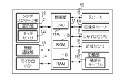
- the front view of the communication terminal device which concerns on 1st Embodiment of this invention The block diagram which shows the hardware constitutions of the communication terminal device which concerns on the same embodiment.
- Explanatory drawing of an example of a communication terminal device and a user's state (at the time of use with a right hand).
- Explanatory drawing of an example of a communication terminal device and a user's state at the time of use with a left hand).
- the flowchart which shows the typical process which the communication terminal device which concerns on 5th Embodiment of this invention performs.
- the block diagram which shows the function structure of the control part which concerns on the modification 6 of this invention.
- the flowchart which shows the process regarding the automatic calling function which the communication terminal device which concerns on the modification performs.
- the flowchart which shows the process following FIG. 20A.
- FIG. 1 is a front view of a communication terminal apparatus 10 according to the first embodiment of the present invention.
- the communication terminal device 10 is a portable communication terminal device that is used by a user.
- the communication terminal device 10 is a smartphone in this embodiment.
- the communication terminal device 10 has the same appearance as a general-purpose smartphone and is formed in a substantially rectangular parallelepiped shape.
- the communication terminal device 10 performs voice transmission and reception for talking.
- the communication terminal device 10 includes a microphone 14 and a speaker 15 on the front side.
- the microphone 14 is a device for inputting transmission voice.
- the microphone 14 is disposed so as to be located near the mouth of the user who is talking.
- the speaker 15 is a device for outputting a received voice.
- the speaker 15 is arranged so as to be located near the head (more specifically, the ear) of the user who is talking.
- the communication terminal device 10 further includes a display area 121A and a proximity sensor 18 on the front side.
- the display area 121A is an area in which an image (screen) of the display unit 121 described later is displayed.
- the proximity sensor 18 is provided adjacent to the speaker 15 and is a sensor for detecting the proximity of the user's head.
- FIG. 2 is a block diagram illustrating a hardware configuration of the communication terminal device 10.
- the communication terminal device 10 includes a control unit 11, a touch screen unit 12, a wireless communication unit 13, a microphone 14, a speaker 15, an acceleration sensor 16, a gyro sensor 17, and a proximity sensor. 18 and a storage unit 19.
- the control unit 11 is a processor including a CPU (Central Processing Unit) 11A as a processing unit, a ROM (Read Only Memory) 11B, and a RAM (Random Access Memory) 11C as a work area.
- CPU11A controls each part of the communication terminal device 10 by reading the program memorize
- the control unit 11 performs various controls for calls, for example.
- the touch screen unit 12 includes a display unit 121 and a touch sensor 122.
- the display unit 121 is a liquid crystal display, for example, and displays an image in the display area 121A (see FIG. 1).
- the touch sensor 122 is a sensor provided in a planar shape over the display region 121A, and a user operation performed on the display region 121A is performed according to a predetermined method (for example, a resistive film method or a capacitance method). Detect.
- the wireless communication unit 13 includes a wireless communication circuit and an antenna, and performs wireless communication.
- the wireless communication unit 13 is a communication unit that connects to a telephone line (not shown) and performs at least communication for a call. For example, the wireless communication unit 13 receives an incoming call or makes a call to a call partner.
- the microphone 14 converts voice input by the user into a voice signal.
- the speaker 15 converts the supplied audio signal into sound and outputs the sound.
- the acceleration sensor 16 is, for example, a triaxial acceleration sensor, and is a sensor that measures acceleration acting on the communication terminal device 10.
- the acceleration sensor 16 is used to measure the attitude or displacement (movement) of the communication terminal device 10.
- the gyro sensor (angular velocity sensor) 17 is, for example, a triaxial angular velocity sensor, and is a sensor that measures an angular velocity acting on the communication terminal device 10.
- the gyro sensor 17 is used for measuring the attitude of the communication terminal device 10.
- the attitude of the communication terminal device 10 at each time point is specified by the inclination (rotation angle) of the communication terminal device 10 from the reference direction.
- the displacement of the communication terminal device 10 is specified by, for example, the locus of movement of the communication terminal device 10.
- the locus is specified by, for example, a combination of the distance moved by the communication terminal device 10 and the direction of movement.
- the proximity sensor 18 is a sensor for detecting the proximity of the user's head.
- the proximity sensor 18 is, for example, an inductive or capacitive proximity sensor, and detects that an object has approached within a predetermined distance.
- the proximity sensor 18 can detect the proximity of the object in each of the non-contact state and the contact state.
- the storage unit 19 includes, for example, an EEPROM (Electronically Erasable and Programmable ROM) or a flash memory, and stores various data.
- the storage unit 19 stores an OS (Operating System) installed in the communication terminal device 10 and various programs operating on the OS.
- the storage unit 19 also stores a call destination table 191 used for control related to the automatic call function.
- the automatic call function is a function for making a call by specifying a call partner without operating a user's operator for instructing the call partner.
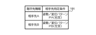
- FIG. 3 is a diagram showing the configuration of the call destination table 191.
- the call destination table 191 is a table in which call destination information and counterpart destination specifying conditions are registered in association with each other party of a call.
- the call destination information is information used for making a call.
- the call destination information is, for example, information that directly or indirectly specifies a telephone number.
- the latter call destination information is, for example, a registration number of a telephone number in an address book or an abbreviated number for abbreviated dialing.
- the call destination information is represented by the name of the other party of the call (the other party A or the other party B).
- the partner identification condition includes a posture or displacement condition of the communication terminal device 10 for identifying the partner of the call.
- the destination identification condition indicates a temporal change in the posture of the communication terminal device 10 and a pattern of displacement when the user uses the communication terminal device 10 with the right hand or the left hand.
- the posture / displacement pattern PA corresponding to the counterpart A indicates a pattern when the user uses the communication terminal device 10 with the right hand.
- the posture / displacement pattern PB corresponding to the other party B indicates a pattern when the user uses the communication terminal device 10 with the left hand.
- the destination identification condition is registered in the call destination table 191 by the user.
- the user takes an operation when making a call while holding the communication terminal device 10 in the right hand or the left hand.
- This operation includes, for example, an operation in which the user holds the communication terminal device 10 with his hand and then approaches the user's head.
- the control unit 11 registers the partner identification condition based on the temporal change and displacement of the attitude of the communication terminal device 10 when this operation is performed.
- the other party identification condition may be registered in the call destination table 191 in advance. Because it is considered that there is a feature in the temporal change and displacement of the attitude of the communication terminal device 10 in each of the case where the communication terminal device 10 is used with the right hand and the case where the communication terminal device 10 is used with the left hand. is there.
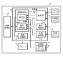
- FIG. 4 is a block diagram illustrating a functional configuration of the control unit 11.
- the control part 11 implement
- the dashed arrows shown in FIG. 4 mean the flow of signals in a fourth embodiment to be described later.
- the measurement unit 111 measures the attitude or displacement of the communication terminal device 10 based on the acceleration measured by the acceleration sensor 16 and the angular velocity measured by the gyro sensor 17.
- the proximity detector 112 detects that the user's head has approached the communication terminal device 10 based on the detection result of the proximity sensor 18.
- the proximity detection unit 112 detects that the user's head has approached the communication terminal device 10 when the proximity sensor 18 detects the proximity of an object.
- the operation detection unit 113 detects that a predetermined operation has been performed by the user using the communication terminal device 10. This operation is an operation that does not include an operation of an operator (for example, an operation of the touch screen unit 12) realized by hardware or software.
- the motion detection unit 113 detects a motion of the user tapping the communication terminal device 10 (for example, the back side) based on the acceleration measured by the acceleration sensor 16.
- the call control unit 114 performs control related to a call.
- Call control unit 114 includes a specifying unit 114A and a call control unit 114B.
- the specifying unit 114A specifies a call partner in the automatic call function.
- the specifying unit 114A changes the posture or displacement measured by the measurement unit 111 before or during detection (that is, while it is being detected). Based on this, the other party of the call is specified.
- the posture or displacement measurement result referred to for identification is, for example, a measurement result of a period or time point corresponding to a time point (timing) when the proximity of the user's head is detected.
- the specifying unit 114A specifies the destination corresponding to the destination specifying condition.
- the call control unit 114B controls the call by the automatic call function.
- the call control unit 114B makes a call to the other party specified by the specifying unit 114A.
- the call control unit 114B makes a call via the wireless communication unit 13 based on the call destination information stored in the call destination table 191.
- the call control unit 114B makes a call when the operation detection unit 113 detects a user operation.
- the notification processing unit 115 performs notification processing for notifying the other party specified by the specifying unit 114 ⁇ / b> A by outputting voice through the speaker 15. For example, the notification processing unit 115 outputs the name of the other party or music associated with the other party (for example, a ringing melody). The notification processing unit 115 does not need to perform the notification processing when the other party is designated by the user through the operation of the operator without using the automatic call function.
- FIG. 5 is a flowchart showing processing relating to the automatic call function executed by the communication terminal device 10.
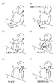
- FIG. 6 is a diagram for explaining an example of the state of the communication terminal device 10 and the user at the time of making a call.
- the control unit 11 repeatedly measures the attitude and displacement of the communication terminal device 10 using the acceleration sensor 16 and the gyro sensor 17 (step S1). During this time, the control unit 11 turns off the proximity sensor 18 and does not detect whether or not an object has approached.
- the control part 11 determines whether the measured attitude
- the control unit 11 determines that the communication terminal apparatus 10 is held by the user's hand when the attitude of the communication terminal apparatus 10 changes with time or when the communication terminal apparatus 10 is displaced.
- FIG. 6A it is assumed that the communication terminal apparatus 10 has been placed face down on a horizontal table T in advance.
- the user U who wants to talk first holds the communication terminal device 10 with his hand (here, the right hand) from the back side.
- the user U lifts the communication terminal device 10 held with the right hand.
- the user U turns the front side of the communication terminal device 10 toward itself.
- acceleration or angular velocity acts on the communication terminal device 10
- the attitude of the communication terminal device 10 changes over time, or the communication terminal device 10 It will be displaced.
- the condition when the communication terminal apparatus 10 is held by the user's hand indicates that at least acceleration or angular velocity has occurred.
- the condition may be, for example, that the posture at one point in time of the communication terminal device 10 is a predetermined posture (for example, an upright posture or a posture close thereto).
- the front face of the communication terminal device 10 in the upright posture is parallel or substantially parallel to the vertical direction.
- the control unit 11 repeatedly measures the attitude and displacement of the communication terminal device 10 until it is determined that the communication terminal device 10 is held by the user's hand (step S2; NO). When it determines with "YES” at step S2, the control part 11 turns ON the proximity sensor 18, and starts the detection of whether the object approached (step S3).
- the control unit 11 determines whether or not the proximity sensor 18 has detected the proximity of the user's head (step S4).
- the control unit 11 repeatedly performs the detection by the proximity sensor 18.
- the user U directs the front side of the communication terminal device 10 to himself / herself (FIG. 6C), and then moves the communication terminal device 10 closer to his / her head as shown in FIG. 6D. .
- the control unit 11 determines that the proximity sensor 18 has detected the proximity of the user's head (step S4; YES).
- control unit 11 specifies the other party of the call based on the attitude or displacement of the communication terminal device 10 measured before or during the detection of the proximity of the user's head (step S5). .
- the control unit 11 determines whether the user has the communication terminal device 10 with the right hand or the left hand based on the measured posture or displacement of the communication terminal device 10 and the other party specifying condition in the call destination table 191. Identify the other party to call.
- the control unit 11 specifies the partner A.
- step S5 the control unit 11 determines from step S2 that the condition when the communication terminal device 10 is held by the user's hand is satisfied (ie, when “YES” is determined), and then the user's head.
- the control unit 11 may refer to the measurement result from the time when the proximity is first detected to the predetermined time before (ie, the measurement result immediately before the proximity is detected) instead of the entire period. .
- the situation for example, the arranged position and posture
- control unit 11 determines whether or not an operation of tapping the communication terminal device 10 by the user has been detected (step S6). When it is determined that the operation of tapping the communication terminal device 10 is not detected (step S6; NO), the control unit 11 stands by as it is.
- step S6 determines “YES” in step S6 and performs a notification process (step S7).
- the control unit 11 outputs sound for notifying the other party via the speaker 15.
- the user who has heard this voice can grasp the call destination of the automatic call function.
- the control unit 11 may further perform a notification process for notifying that a call is to be made by the automatic call function using a vibration function or the like.
- control unit 11 makes a call to the destination via the wireless communication unit 13 based on the specified destination information of the destination (step S8).
- the control unit 11 makes a call to the destination A as shown in FIG.
- the control unit 11 determines whether or not there is a response from the other party (step S9).
- the control unit 11 establishes a communication path for the call via the telephone line and starts the call (step S10). Thereafter, the control unit 11 performs control for calling.
- step S9 If it is determined as “NO” in step S9, that is, if it is determined that the caller is waiting for a response from the other party, the control unit 11 uses the proximity sensor 18 to approach the user's head. It is determined whether or not it is no longer detected (step S11). When it is determined that the proximity of the user's head is being detected (step S11; NO), the control unit 11 returns to step S9. When it is determined that the proximity of the user's head is no longer detected (step S11; YES), the control unit 11 stops calling (step S12). The fact that the proximity of the user's head is no longer detected is because the intention of making a call using the communication terminal device 10 may have been lost. Note that the control unit 11 turns off the proximity sensor 18 after the start of the call or after the end of the call.
- the communication terminal device 10 makes a call to the partner A when held by the user's right hand.
- the communication terminal apparatus 10 performs the process described with reference to FIG.
- the user U uses the communication terminal device 10 with his left hand
- the user U holds the communication terminal device 10 with his left hand (FIG. 7A) and lifts it as it is (FIG. 7B).
- the user U brings the communication terminal device 10 close to his / her head toward the front side of the communication terminal device 10 (FIG. 7C) (FIG. 7D).
- the user U performs an operation of tapping the communication terminal device 10 when starting a call (FIG. 7E).
- communication terminal apparatus 10 makes a call to destination B as shown in FIG.
- the communication terminal device 10 when it is detected that the communication terminal device 10 has been moved so as to be close to the user's head, the communication terminal device 10 specifies the other party of the call based on the attitude and displacement detected during this time. Therefore, the user of the communication terminal device 10 can perform a natural operation when talking while holding the communication terminal device 10 in his / her hand, so that the user of the communication terminal device 10 can make a call to the other party he / she desires without operating the operator. Can be called.
- the communication terminal device 10 makes a call when detecting a tapping operation by the user. Therefore, the possibility that the communication terminal apparatus 10 makes a call at an incorrect timing by the automatic call function is reduced. Furthermore, the user does not need to perform an operation of the operation element (for example, an operation of the touch screen unit 12) to instruct the other party or to issue a call. For this reason, even when the user is unfamiliar with the operation of the touch screen unit 12, a feeling of burden of the operation for starting a call can be reduced.
- the operation element for example, an operation of the touch screen unit 12
- the communication terminal device 10 specifies the other party of the call based on the posture measured at one point in time when the proximity of the user's head is being detected.
- This posture is, for example, the posture when the communication terminal device 10 is in contact with the user's head (ear).
- symbol as 1st Embodiment mentioned above functions equivalent to 1st Embodiment mentioned above.
- the hardware configuration and functional configuration of the communication terminal apparatus 10 of the present embodiment are substantially the same as those of the first embodiment described above.
- the specifying unit 114A specifies the other party of the call based on the posture measured at one time point during detection of the proximity of the user's head.
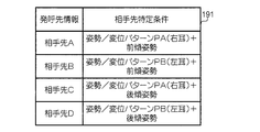
- FIG. 8 is a diagram showing the configuration of the call destination table 191 of the present embodiment.
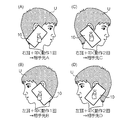
- FIG. 9 is a diagram illustrating a posture measured during detection of the proximity of the user's head.
- call destination information and destination identification conditions are registered for each of the destinations A to D.
- the partner specifying condition corresponding to the partner A is specified by the same posture / displacement pattern PA and the forward tilt posture as in the first embodiment described above.
- the forward leaning posture is a posture inclined so that the height of the communication terminal device 10 decreases toward the front as seen from the user U.
- the other party A is called.
- the partner specifying condition corresponding to the partner B is specified by the same posture / displacement pattern PB and the forward tilt posture as in the first embodiment described above. As shown in FIG. 9B, when the user U puts the communication terminal device 10 on the left ear and puts it in a forward leaning posture, the call is made to the partner B.
- the partner specifying condition corresponding to the partner C is specified by the posture / displacement pattern PA and the backward tilt posture.
- the backward tilted posture is a posture tilted so that the height of the communication terminal device 10 decreases toward the rear as viewed from the user U.
- the partner specifying condition corresponding to the partner D is specified by the posture / displacement pattern PB and the backward tilt posture.
- FIG. 9D when the user U puts the communication terminal apparatus 10 on the left ear and sets the user terminal 10 in a backward inclined posture, the call is made to the partner D.
- the posture of the communication terminal apparatus 10 after the call destination is specified does not have to be the postures described with reference to FIGS. 9A to 9D, and may be a posture in which the user can easily talk. .
- the processing related to the automatic call function executed by the communication terminal device 10 is substantially the same as the processing described in FIG.
- the control unit 11 of the communication terminal device 10 measures the posture by the gyro sensor 17 at one point in time when the communication terminal device 10 is detecting the proximity of the user's head, and either the forward leaning posture or the backward leaning posture. Determine whether.
- the time of this measurement may be during proximity detection, but is, for example, the time when the communication terminal device 10 is closest to the user's head, more specifically, the time when the user touches the user's head.
- step S5 the control unit 11 refers to the call destination table 191 based on the hand held by the user and the posture measured at one time point when the proximity of the user's head is being detected. Identify the other party. Other processes are as described in the first embodiment.
- the communication terminal device 10 can increase the types of counterparts that can be called with the automatic call function, compared to the configuration of the first embodiment described above.
- the communication terminal apparatus 10 may specify the other party of the call based only on the posture measured at one time point during detection of the proximity of the user's head.
- the forward leaning posture and the backward leaning posture described above are only examples of postures during proximity detection.
- the posture during proximity detection may be further subdivided. This further increases the types of destinations that can be called by the automatic call function.
- the communication terminal device 10 specifies a call partner based on an operation performed by the user using the communication terminal device 10 in addition to a user using the communication terminal device 10.
- symbol as 1st Embodiment mentioned above functions equivalent to 1st Embodiment mentioned above.
- the hardware configuration and functional configuration of the communication terminal apparatus 10 of the present embodiment are substantially the same as those of the first embodiment described above.
- the specifying unit 114A specifies the other party of the call based on the measured attitude of the communication terminal device 10 and the operation detected during the detection of the proximity of the user's head. This operation is an operation of hitting the communication terminal device 10 as described above.
- FIG. 10 is a diagram showing the configuration of the call destination table 191 of this embodiment.
- FIG. 11 is a diagram illustrating an operation performed by the user during detection of proximity of the user's head.
- call destination information and destination identification conditions are registered for each of the destinations A to D.
- the other party specifying condition corresponding to the other party A is specified by the same posture / displacement pattern PA as in the first embodiment and the operation of tapping the communication terminal device 10 once.
- FIG. 11 (A) when the user U puts the communication terminal device 10 on the right ear and performs a single tapping operation, the call is made to the destination A.
- the other party specifying condition corresponding to the other party B is specified by the same posture / displacement pattern PB as in the first embodiment and the operation of tapping the communication terminal device 10 once. As shown in FIG. 11 (B), when the user U puts the communication terminal device 10 on the left ear and performs a single tapping operation, the other party B is called.
- the partner specifying condition corresponding to the partner C is specified by the posture / displacement pattern PA and the operation of tapping the communication terminal device 10 twice.
- the call is made to the destination C.
- the partner specifying condition corresponding to the partner D is specified by the posture / displacement pattern PB and the operation of tapping the communication terminal device 10 twice.
- FIG. 11 (D) when the user U puts the communication terminal device 10 on the left ear and taps twice, the call is made to the destination D.
- FIG. 12 is a flowchart showing processing relating to the automatic calling function executed by the communication terminal device 10.
- the control unit 11 performs the processes of steps S1 to S4 and then determines that the user has detected an operation of tapping the communication terminal device 10 (step S6; YES)
- the measured attitude of the communication terminal device 10 is determined.
- the other party of the call is specified (step S13).
- the control unit 11 refers to the call destination table 191 and identifies the other party of the call.
- the control unit 11 executes the processing steps of steps S7 to S12 in the same procedure as in the first embodiment described above.
- the communication terminal device 10 can increase the types of destinations that can be called with the automatic call function as compared with the configuration of the first embodiment described above.
- the communication terminal device 10 performs the call based on the posture measured at one time point during the proximity detection of the user's head described in the second embodiment and the tapping operation performed by the user.
- the other party may be specified.
- the number of hitting operations described above may be three or more. This further increases the types of destinations that can be called by the automatic call function. Further, instead of the number of hitting operations, the strength or pattern of the hitting operation may be used.
- the communication terminal device 10 according to each of the embodiments described above has stopped calling when it has stopped detecting the proximity of the user's head after starting calling in step S8.
- the communication terminal device 10 according to the present embodiment specifies a posture as a condition for canceling the call according to the posture of the communication terminal device 10 after the start of the call.
- symbol as 1st Embodiment mentioned above functions equivalent to 1st Embodiment mentioned above.
- the hardware configuration and functional configuration of the communication terminal device 10 of the present embodiment are substantially the same as those of the first embodiment described above.
- the posture or displacement satisfying a predetermined condition (hereinafter referred to as “call stop condition”) is measured by the measurement unit 111 after starting a call to the specified partner. If the call is canceled, the call is canceled.
- FIG. 13 is a flowchart showing processing relating to the automatic calling function executed by the communication terminal device 10.
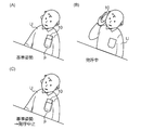
- FIG. 14 is a diagram for explaining an example of the state of the communication terminal device 10 and the user at the time of making a call.
- the control unit 11 specifies the reference posture (step S14).
- the reference posture is a posture before the communication terminal device 10 is held by the user's hand.
- FIG. 14A when the communication terminal device 10 is stored in the chest pocket P of the user U, the control unit 11 changes the posture of the communication terminal device 10 shown in FIG. As specified.
- the control unit 11 causes the storage unit 19 to store posture data indicating the reference posture.
- step S8 the control unit 11 starts a call in step S8, and if it is determined that there is no response from the other party (step S9; NO), the control unit 11 proceeds to step S15. And the control part 11 measures the present attitude
- the calling stop condition is that the posture measured in step S15 indicates the reference posture indicated by the posture data stored in the storage unit 19.
- step S16; NO the control unit 11 returns to step S9 and stands by.
- step S15 indicates the reference posture
- step S16 indicates the reference posture
- step S12 the control unit 11 stops calling.
- FIG. 14B when the user U puts the communication terminal device 10 on his / her ear, a call is being made by the automatic call function. Thereafter, when the user U stores the communication terminal device 10 in the breast pocket P, the communication terminal device 10 assumes a reference posture or a posture close thereto as shown in FIG. Therefore, the control unit 11 stops calling.
- the call suspension condition may include a condition other than the measured posture indicating the reference posture.
- the control unit 11 may determine that the call stop condition is satisfied when a change in posture of a predetermined angle or more is measured from the time when the call is started. Further, the control unit 11 cancels the call when the temporal change or displacement of the attitude of the communication terminal device 10 indicates the reverse order of the temporal change of the attitude and displacement measured when there is an incoming call. You may determine with satisfy
- the communication terminal device 10 of the present embodiment even when the user does not operate the operation element, a natural operation that the user takes when talking while holding the communication terminal device 10 in his / her hand is detected and a call is made. Can be canceled.
- the communication terminal device 10 according to the present embodiment like the first embodiment described above, makes a call when it is determined that the proximity of the user's head is no longer detected after the call is started in step S8. You may cancel.
- the communication terminal device 10 is stored in the breast pocket P has been described in the present embodiment, the same effect can be obtained when the communication terminal device 10 is arranged in another place or in another posture.
- the communication terminal device 10 of the present embodiment is different from the configuration of each of the embodiments described above in that it is not permitted to make a call using the automatic call function during a period in which sound is output. This is because there is a possibility that functions other than the automatic calling function may be used by the user in the communication terminal device 10 during this period.
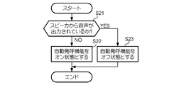
- FIG. 15 is a flowchart illustrating typical processing executed by the communication terminal device 10 according to the present embodiment.
- the communication terminal device 10 sequentially executes the processing illustrated in FIG. 15 during a period in which the power is on.
- the control unit 11 of the communication terminal device 10 determines whether or not sound is output via the speaker 15 (step S21).
- the control unit 11 determines whether or not sound is output via the speaker 15 based on an audio signal representing the sound collected by the microphone 14.
- the control unit 11 determines that the sound is output when the level (for example, the volume) of the audio signal is equal to or higher than the threshold, and the audio is not output when the level of the audio signal is lower than the threshold. judge.
- control unit 11 may determine that sound is output via the speaker 15 on the condition that the sound signal indicates an electronic sound. Further, the control unit 11 may acquire an audio signal supplied to the speaker 15 and determine whether or not audio is output from the speaker 15. In this case, the control unit 11 analyzes the acquired audio signal and determines the presence or absence of audio output based on, for example, a temporal change in the audio waveform.
- step S21 When it is determined that the voice is not output in step S21 (step S21; NO), the control unit 11 turns on the automatic calling function (step S22).
- step S ⁇ b> 22 the control unit 11 causes the RAM 11 ⁇ / b> C or the storage unit 19 to store a permission flag that is a flag that permits the use of the automatic call function, for example.
- the control unit 11 permits the call to the other party specified by the automatic call function during the period in which the permission flag is stored.
- step S21 When it is determined that the voice is output in step S21 (step S21; YES), the control unit 11 turns off the automatic calling function (step S23).
- step S23 the control unit 11 causes the RAM 11C or the storage unit 19 to store a prohibition flag that is a flag for prohibiting the use of the automatic call function, for example.
- the control unit 11 does not execute the process related to the automatic call function, and does not allow (that is, prohibits) calling to the other party specified by the automatic call function. ).
- the communication terminal apparatus 10 makes a call based on a call function different from the automatic call function.
- This call function is executed based on an application program stored in the storage unit 19, for example.
- the control unit 11 performs a call based on the call function, so that the voice related to the call function (for example, a melody used during the call) is output through the speaker 15. Does not allow calls made by the automatic call function.
- the communication terminal device 10 reproduces content (for example, audio content or moving image content) and outputs audio via the speaker 15.
- content for example, audio content or moving image content
- the user may take the operations described with reference to FIGS. 6 and 7 because he or she wants to listen to the sound from the speaker 15 well.
- the control unit 11 does not permit making a call by the automatic call function during a period in which sound related to the reproduced content is being output through the speaker 15.
- the control unit 11 is not limited to a period in which sound is output through the speaker 15, but is automatically used in a period in which the communication terminal device 10 outputs sound through an external device such as an externally connected earphone or speaker. It may not be permitted to make a call by the call function. According to the communication terminal device 10 of the present embodiment described above, it is possible to avoid making a call at an incorrect timing by the automatic call function using the voice output from the communication terminal device 10 as a clue. . In the present embodiment, it is configured such that calling by the automatic calling function is not permitted during a period in which voice is output from the communication terminal device 10.
- the communication terminal device 10 is not limited to voice output. For example, when a voice translation function is used, the user has a function that is undesirable when the automatic call function is manifested or a function that competes with the automatic call function. When using, it is good also as not permitting the call by an automatic call function.
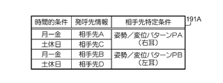
- FIG. 16 is a diagram illustrating a configuration of a call destination table 191A according to (Configuration Example 1). As shown in FIG. 16, the call destination table 191A is a table in which temporal conditions, call destination information, and destination identification conditions are registered in association with each other.
- the time conditions are divided into two groups of days of the week: “Monday-Friday” (weekday Monday-Friday) and “Saturday / Holiday”.
- call destination information of call destinations that are different from each other in the time conditions “Monday-Friday” and “Saturday / Holiday” is associated with one destination specification condition. Yes.
- the destination information of “partner A” is “Monday-Friday”
- the destination information of “partner C” is “Saturday / Holiday”. It is associated.
- the “destination B” call destination information corresponds to “Monday-Friday”
- the “destination D” call destination information corresponds to “Monday-Friday”. It is attached.
- Opponents A and B are, for example, people at work, where the user has relatively many opportunities to talk on weekdays.
- the counterparts C and D are relatively frequent opportunities for the user to talk on holidays, for example, friends.
- step S5 the control unit 11 (specifying unit 114A) specifies the other party of the call based on the measured posture and displacement and the time when the posture and displacement are measured (here, the day of the week at the time of measurement). .
- the control unit 11 selects “partner A” if the day is “Monday-Friday”, and “Saturday / Holiday”. Specify "Destination C”.
- the control unit 11 selects “partner B” if the day is “Monday-Friday”, and “ Specify "Destination D”.
- control part 11 performs the process after step S6, and makes a call to the specified other party.
- the temporal condition may be specified by a temporal element other than the day of the week, such as time, date, or month. Further, the time condition may be divided into three or more.
- the communication terminal device 10 can change the call destination by the automatic call function according to the time condition that is satisfied when the user tries to talk.
- the call destination table 191A the call destination information of the other party with whom the user often talks when the time conditions are satisfied is registered, so that the communication terminal device 10 can accurately identify the other party with whom the user is going to talk. Can be specified.
- FIG. 17 is a diagram illustrating a configuration of a call destination table 191B according to (Configuration Example 2).
- the call destination table 191B is a table in which location conditions, call destination information, and destination identification conditions are registered in association with each other.
- the place conditions are divided into two place groups, “work place” and “non-work place”.
- the location condition information is represented by, for example, latitude and longitude information, but may be represented by other information.
- the call destination information of the call destinations that are different for the place conditions “work place” and “non-work place” is associated with one destination specification condition. Yes.
- the “destination A” call destination information is “work place”, and the “destination C” call destination information is “non-work place”. It is associated. Also, for “posture / displacement pattern PB”, the “destination B” call destination information corresponds to "work place”, and the “destination D” call destination information corresponds to "non-work place” It is attached.
- Opponents A and B are relatively frequent opportunities for users to talk on the phone during work, for example, people at work.
- Opponents C and D have relatively many opportunities to talk on occasions other than when the user is on duty, for example, friends.
- step S5 the control unit 11 (specifying unit 114A) specifies the other party of the call based on the measured posture and displacement and the location (position) where the posture and displacement are measured.
- the control unit 11 identifies the location of the communication terminal device based on a positioning function (for example, a GPS (Global Positioning System) positioning function) or a base station positioning function provided in the communication terminal device 10. Then, when the posture and displacement indicating the “posture / displacement pattern PA” are measured and the location at the time of the measurement indicates “work place”, the control unit 11 designates “partner A” as “work place”. When “other than” is indicated, “partner C” is specified.
- a positioning function for example, a GPS (Global Positioning System) positioning function
- the control unit 11 designates “partner B” as “work place”. When “other than” is indicated, “destination D” is specified. And the control part 11 performs the process after step S6, and makes a call to the specified other party.
- the work place may be specified by another place element (positional element) such as a home or a travel destination. Further, the location condition may be divided into three or more.
- the communication terminal apparatus 10 can change the call destination by the automatic call function according to the locational conditions that are satisfied when the user attempts to talk.
- the call destination table 191B the call destination information of the other party with whom the user often makes a call when each location condition is satisfied is registered, so that the communication terminal apparatus 10 accurately identifies the other party with whom the user is going to talk. Can be specified.
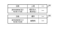
- FIG. 18 is a diagram showing a configuration of user schedule data 192 of the communication terminal device 10 stored in the storage unit 19.
- the schedule data 192 is generated and stored based on a scheduler executed by the control unit 11.
- the scheduler is software for managing a user's schedule.
- the schedule data 192 includes, for example, an event registered in the scheduler (for example, a schedule of behavior), a date and time when the event is scheduled to be performed, a person (for example, a participant / accompanying person) related to the event, and the event Contains information on where is implemented.
- step S ⁇ b> 5 the control unit 11 (specification unit 114 ⁇ / b> A) specifies the other party of the call based on the measured posture and displacement and the user's schedule data 192.
- the schedule data 192 shown in the upper part of FIG. 18 is stored at the time when the posture and displacement indicating the predetermined posture / displacement pattern are measured, or the date and time at the time within the predetermined period from that time is specified.
- the control unit 11 sets a person related to the event as a candidate for a call partner.
- the control part 11 makes the other party A and the other party D the candidate of the other party of a telephone call.
- the control unit 11 measures “the other party A”, and when measuring the posture and the displacement indicating “posture / displacement pattern PB”. Is identified as “Destination D”.
- the control unit 11 specifies the correspondence relationship between the posture / displacement pattern and the person related to the event based on the designation by the user, but may be specified by other methods.
- the other party of the call may be specified by the following method. However, it is assumed that the call destination table 191B shown in FIG.
- the schedule data 192 shown in the lower part of FIG. 18 is stored in which the date and time when the posture and displacement indicating the predetermined posture / displacement pattern are measured, or the time and date within the predetermined period from that time are specified. Think about the case.
- the control unit 11 specifies the other party of the call based on the place where the event is performed.
- the control unit 11 sets the other party associated with the place condition “work place” in the call destination table 191B as the event.
- a candidate for a call partner is assumed. For example, when the posture and displacement indicating the “posture / displacement pattern PA” are measured, the control unit 11 measures “the other party A”, and when measuring the posture and the displacement indicating “posture / displacement pattern PB”. Is identified as “partner B”.
- the communication terminal apparatus 10 can change the call destination by the automatic call function according to the schedule data 192.
- the communication terminal device 10 can accurately specify the partner with whom the user wants to talk based on the schedule data 192.
- the communication terminal device 10 may include two or more configurations of (Configuration Example 1) to (Configuration Example 3).
- the present invention can be implemented in a form different from the above-described embodiment.
- the present invention can also be implemented in the following forms, for example. Further, the following modifications may be combined as appropriate.
- (Modification 1) The communication terminal device 10 may have a configuration in which the configurations according to two or more of the first to sixth embodiments described above are combined.
- the communication terminal device 10 may detect an operation other than an operation performed by the user in the automatic call function.
- the operation performed by the user using the communication terminal device 10 may be another operation in which the user applies an external force to the communication terminal device 10.
- the control unit 11 may make a call on condition that the motion of shaking the communication terminal device 10 is detected by using the acceleration sensor 16 while detecting the proximity of the user.
- the operation performed by the user using the communication terminal device 10 may be a user's utterance.
- the control unit 11 may make a call on condition that the user's utterance is detected via the microphone 14 during the detection of the proximity of the user.
- the communication terminal device 10 may perform a call using the automatic call function when detecting an operation that is performed when the user can talk and is not operated by the operator.
- the condition for making a call by the automatic call function is not limited to the detection of the operation performed by the user.
- the control unit 11 of the communication terminal apparatus 10 continues from the time when the proximity sensor 18 detects the proximity of the user's head or the other party is specified, and continues for a predetermined period.
- the stationary state is a state where no change or displacement of the attitude of the communication terminal apparatus 10 is detected.
- the control part 11 may perform a call immediately, if the other party of a telephone call is specified.
- the communication terminal device 10 may make a call when an operation of an operation member instructing a call by the user is accepted after specifying a communication partner. For example, if the control unit 11 of the communication terminal device 10 specifies the other party of the call, the control unit 11 displays information on the other party using the display unit 121. The user looks at the display of this information, and when a desired destination is specified, the user performs an operation for instructing a call using, for example, the touch screen unit 12. Even in this case, since the user does not need to perform an operation of instructing the other party of the call, the burden on the user's operation is reduced compared to the case where this operation is required.
- control unit 11 may specify two or more call destinations and display the information on the other end points using the display unit 121.
- the user performs an operation for instructing the destination of the call destination from the two or more specified destinations of the call. Even in this case, for example, the burden on the user's operation is reduced as compared with a case where the user performs an operation of instructing a call partner using the address book.
- the control unit 11 of the communication terminal device 10 may perform the notification process by using the ringback tone as a voice corresponding to the other party of the call. For this reason, in the exchange that transmits the ringback tone, the ringback tone to be used is defined corresponding to the combination of the communication terminal device 10 that is the caller and the other party. When the exchange specifies the combination of the communication terminal device 10 that is the caller and the other party, the exchange transmits a ringback tone corresponding to this combination. The control unit 11 of the communication terminal device 10 outputs the ringback tone transmitted by the exchange through voice through the speaker 15. Thereby, the said other party can be grasped
- FIG. 19 is a block diagram illustrating a functional configuration of the control unit 11 of the communication terminal device 10 according to the present modification. As shown in FIG. 19, in the control unit 11, in addition to the functions of the first embodiment described above, a function corresponding to the display control unit 114C is realized in the call control unit 114.
- the display control unit 114C When the display control unit 114C detects that a predetermined operation has been performed by the user using the communication terminal device 10, the display control unit 114C displays a destination of a call to be called by the automatic call function.
- the displayed partner screen is displayed on the display unit 121.
- the partner screen is a screen showing the partner of the call by the automatic call function.
- the partner screen is displayed based on the information in the call destination table 191, for example.
- the predetermined operation is an operation of shaking the communication terminal device 10 here, but may be the other operation described in the second modification. In addition, this motion detection is performed by the motion detection unit 113 in this modification.
- the call control unit 114B is identified based on the posture or displacement measured by the measurement unit 111 within the display period. A call is made to the called destination. In other words, the call control unit 114B does not allow the call to be made outside the screen display period of the partner screen. In this modification, the period during which a call can be made by the automatic call function is limited to the screen display period of the partner screen.
- control unit 11 determines whether or not the motion of shaking the communication terminal device 10 is detected using the acceleration sensor 16 (step S21 in FIG. 20A). When it determines with "YES" at step S21, the control part 11 displays the other party screen on the display part 121 (step S22).
- FIG. 21 is a diagram showing an example of the destination screen.
- the other party of the call is displayed in association with the operation necessary for making a call to the other party using the automatic call function.
- the message “right ear partner A” and “left ear partner B” is displayed on the partner screen SC.
- the user who has seen the other party screen SC can grasp an operation necessary for making a call to the other party desired by the user.
- step S22 the control unit 11 proceeds to the process of step S1. Then, the control unit 11 displays the partner screen within the screen display period (for example, 5 seconds), and ends the display of the partner screen when it is outside the screen display period. Specifically, if the control unit 11 determines “NO” in step S2, determines “NO” in step S4, and determines “NO” in step S6, the control unit 11 It is determined whether the screen display period has elapsed (steps S23, S24, S25). When it is determined “NO” in step S23, the control unit 11 performs the process of step S1, when it determines “NO” in step S24, the process of step S4, and when it determines “NO” in step S24. The process returns to step S6.
- the length of the screen display period is a fixed value, for example. When it determines with "YES” by step S23, S24, or S25, the control part 11 complete
- the control unit 11 determines whether or not the measured posture and displacement satisfy the condition when the communication terminal apparatus 10 is held by the user's hand within the display period of the partner screen (that is, “YES” in step S2). )), And when it is determined that the proximity of the user's head has been detected by the proximity sensor 18 (that is, “YES” in step S4), it is permitted to make a call using the automatic call function (that is, step S8). Allow the process to run). Further, as described above, the destination screen is displayed when a predetermined operation is performed by the user using the communication terminal device 10. Therefore, according to the communication terminal device 10 of the present modification, it is possible to reduce the possibility that a call is erroneously made at a timing not intended by the user.
- control unit 11 may make a call at step S8 without the determination at step S6.
- the other party screen which is a condition for making a call by the automatic call function, is displayed when a predetermined operation is performed by the user using the communication terminal device 10, so that an error occurs at a timing not intended by the user. The possibility of making a call is reduced.
- control unit 11 may change the length of the screen display period.
- the control unit 11 sets the screen display period with a length according to the user setting.
- the control part 11 is good also as a screen display period of the length according to the surrounding environment of the communication terminal device 10 (or its user).
- the control unit 11 has a brighter environment (for example, the illuminance is lower).
- the screen display period is made longer than when it is placed above the threshold).
- the control unit 11 determines that the size is relatively large (for example, the size is equal to or larger than the threshold) than the case where the size is smaller (for example, the size is smaller than the threshold)
- the screen display period may be lengthened.
- control part 11 may change the length of a screen display period according to another condition.
- the communication terminal device 10 may realize an automatic call function based on one of the posture and displacement of the own device.
- the measurement unit 111 measures one of the posture and the displacement of the communication terminal device 10. That is, the communication terminal device 10 may realize the automatic call function based on at least one of the posture and displacement of the own device.
- the communication terminal device 10 may not perform the notification process when making a call with the automatic call function.
- the communication terminal device 10 may continuously operate the proximity sensor 18 during a period in which the power is on. Further, the above-described sensor included in the communication terminal device 10 is merely an example.
- the communication terminal device 10 is not limited to a smartphone, and may be another portable communication terminal device that performs communication for a call, such as a feature phone.
- this communication terminal device the part that the user uses in his / her hand functions as a transmitter / receiver for transmitting and receiving speech.
- the communication terminal device of the present invention can also be applied to a communication terminal device that generates bone conduction sound indicating a voice including received voice on the user's body, that is, a communication terminal device that includes a speaker that outputs bone conduction sound.
- This communication terminal device is configured so that the user can make a call even if it is brought into contact with a part of the head other than the user's ear.
- the communication terminal device of the present invention may not be a communication terminal device that the user holds and uses during a call.
- the communication terminal device of the present invention may be a so-called wearable terminal that is used by being worn on a user's head, such as a headphone type or an earphone type.
- the communication terminal device of the present invention is not limited to a portable communication terminal device, and may be a communication terminal device including a handset, such as a fixed (stationary) communication terminal.
- This communication terminal device includes, for example, a telephone body that performs communication for a call, and a handset that is used by a user to hold the call.
- Examples of such a communication terminal device include a telephone in which a telephone body and a handset are connected via a cord (wired), and a cordless telephone in which the telephone body and a handset are connected wirelessly.
- the configuration and operation of the communication terminal device according to this modification are described by replacing the orientation and displacement of the communication terminal device 10 described in the above embodiments with the orientation and displacement of the handset, respectively. By explaining the proximity of the user's head to the proximity of the user's head to the handset and replacing the user's operation using the communication terminal device 10 with the user's operation using the handset. it can.
- the functions realized by the control unit 11 of the communication terminal device 10 of each embodiment described above can be realized by a combination of a plurality of programs, or can be realized by linkage of a plurality of hardware resources.
- the program includes a magnetic recording medium (magnetic tape, magnetic disk (HDD (Hard Disk Drive), FD (Flexible Disk)), etc.), optical recording medium (optical disk). Etc.), may be provided in a state stored in a computer-readable recording medium such as a magneto-optical recording medium or a semiconductor memory, or distributed via a network.
- the present invention can also be understood as a call control method.
- DESCRIPTION OF SYMBOLS 10 Communication terminal device, 11 ... Control part, 111 ... Measuring part, 112 ... Proximity detection part, 113 ... Motion detection part, 114 ... Call control part, 114A ... Specific part, 114B ... Call control part, 114C ... Display control 115, notification processing unit, 12 ... touch screen unit, 121 ... display unit, 121A ... display area, 122 ... touch sensor, 13 ... wireless communication unit, 14 ... microphone, 15 ... speaker, 16 ... acceleration sensor, 17 ... Gyro sensor, 18 ... proximity sensor, 19 ... storage unit, 191, 191A, 191B ... call destination table, 192 ... schedule data.
Landscapes
- Engineering & Computer Science (AREA)
- Theoretical Computer Science (AREA)
- Human Computer Interaction (AREA)
- General Engineering & Computer Science (AREA)
- Signal Processing (AREA)
- Computer Hardware Design (AREA)
- Physics & Mathematics (AREA)
- General Physics & Mathematics (AREA)
- Computer Networks & Wireless Communication (AREA)
- Environmental & Geological Engineering (AREA)
- Telephone Function (AREA)
- User Interface Of Digital Computer (AREA)
Abstract
Description
これに対し、本発明の目的は、通話するときにユーザが一般的にとる動作によって、当該ユーザの操作子の操作なしで通話の相手先を特定することである。
本発明の通信端末装置において、前記特定部は、前記近接が検知されている間の一の時点に計測された前記姿勢に基づいて、前記相手先を特定してもよい。
本発明の通信端末装置において、前記ユーザにより前記通信端末装置を用いて予め決められた動作が行われたことを検知する動作検知部を備え、前記発呼制御部は、前記動作が検知された場合に、特定された前記相手先に発呼を行ってもよい。
この通信端末装置において、前記特定部は、計測された前記姿勢又は変位と、前記近接が検知されている間に検知された前記動作とに基づいて、前記相手先を特定してもよい。
本発明において、前記ユーザにより前記通信端末装置を用いて予め決められた動作が行われたことを検知する動作検知部と、前記通信端末装置を用いて予め決められた動作が行われたことが検知された場合に、前記特定部により特定される対象の前記相手先を示した相手先画面を、表示部に表示させる表示制御部とを備え、前記発呼制御部は、前記相手先画面の表示期間内に前記近接が検知された場合には、当該表示期間内に計測された姿勢又は変位に基づいて特定された発呼先に発呼を行ってもよい。
本発明の通信端末装置において、特定された前記相手先を音声の出力により報知する報知処理部を備えてもよい。
本発明の通信端末装置において、前記発呼制御部は、特定された前記相手先に発呼を開始した後に、所定の条件を満たす前記姿勢又は変位が計測された場合には、当該発呼を中止してもよい。
本発明の通信端末装置において、前記特定部は、所定の前記姿勢又は変位が計測された場合に特定する前記相手先を、当該計測が行われた時点、当該計測が行われた場所、又は前記ユーザのスケジュールデータに応じて変化させてもよい。
[第1実施形態]
図1は、本発明の第1実施形態に係る通信端末装置10の正面図である。通信端末装置10は、ユーザが手に持って使用する、携帯型の通信端末装置である。通信端末装置10は、本実施形態ではスマートフォンである。通信端末装置10は、汎用のスマートフォンと同じ外観で、ほぼ直方体状に形成されている。
制御部11は、演算処理装置としてのCPU(Central Processing Unit)11A、ROM(Read Only Memory)11B、及びワークエリアとしてのRAM(Random Access Memory)11Cを備えたプロセッサである。CPU11Aは、ROM11B又は記憶部19に記憶されたプログラムを、RAM11Cに読み出して実行することにより、通信端末装置10の各部を制御する。制御部11は、例えば通話のための各種制御を行う。
発呼先情報は、通話の発呼を行うために用いられる情報である。発呼先情報は、例えば、電話番号を直接的又は間接的に特定する情報である。後者の発呼先情報は、例えば、アドレス帳における電話番号の登録番号や、短縮ダイヤルのための短縮番号である。図3では、発呼先情報を、通話の相手先の名称(相手先A又は相手先B)で表している。
計測部111は、加速度センサ16により計測された加速度と、ジャイロセンサ17により計測された角速度とに基づいて、通信端末装置10の姿勢又は変位を計測する。
特定部114Aは、自動発呼機能における通話の相手先を特定する。特定部114Aは、近接検知部112により近接が検知された場合に、当該近接が検知される前又は検知中(つまり、検知されている間)に、計測部111により計測された姿勢又は変位に基づいて、通話の相手先を特定する。この特定のために参照される姿勢又は変位の計測結果は、例えば、ユーザの頭部の近接が検知された時点(タイミング)に応じた期間又は時点の計測結果である。特定部114Aは、計測された姿勢の時間的な変化及び変位が、発呼先テーブル191の相手先特定条件を満たした場合に、当該相手先特定条件に対応する相手先を特定する。
図5は、通信端末装置10が実行する自動発呼機能に関する処理を示すフローチャートである。図6は、通話の発呼時における通信端末装置10及びユーザの状態の一例を説明する図である。
制御部11は、加速度センサ16、及びジャイロセンサ17を用いて、通信端末装置10の姿勢及び変位を繰り返し計測する(ステップS1)。この間、制御部11は、近接センサ18をオフし、物体が近接したかどうかの検知を行っていないものとする。
ここで、図6(A)に示すように、通信端末装置10が、予め水平なテーブルTに裏向きに置かれていたとする。この場合、通話しようとするユーザUは、まず、通信端末装置10を背面側から手(ここでは右手)で握る。次に、図6(B)に示すように、ユーザUは、右手で握った通信端末装置10を持ち上げる。次に、図6(C)に示すように、ユーザUは、通信端末装置10の正面側を自身に向ける。このように、通信端末装置10がユーザの手で持たれたときには、通信端末装置10に加速度又は角速度が作用して、通信端末装置10の姿勢が時間的に変化したり、通信端末装置10が変位したりする。
なお、通信端末装置10がユーザの手で持たれたときの条件は、少なくとも、加速度又は角速度が発生したことを示す。当該条件は、例えば、通信端末装置10の一の時点の姿勢が、所定の姿勢(例えば、直立姿勢又はそれに近い姿勢)であることであってもよい。直立姿勢となった通信端末装置10は、その正面が鉛直方向に平行又はほぼ平行となる。
ユーザUは、通信端末装置10の正面側を自身に向けた後(図6(C))、図6(D)に示すように、通信端末装置10を自身の頭部に近づけるように移動させる。図6(D)に示す状態となったとき、制御部11は、近接センサ18によりユーザの頭部の近接を検知したと判定する(ステップS4;YES)。
発呼の開始後、制御部11は、相手先の応答があったかどうかを判定する(ステップS9)。制御部11は、この応答があったと判定した場合は(ステップS9;YES)、電話回線を介して通話のための通信路を確立して、通話を開始させる(ステップS10)。以降、制御部11は、通話のための制御を行う。
なお、制御部11は、通話の開始後、又は通話を終了させた後は、近接センサ18をオフする。
本実施形態の通信端末装置10は、ユーザにより持たれた手に加え、ユーザの頭部の近接の検知中の一の時点に計測した姿勢に基づいて、通話の相手先を特定する。この姿勢は、例えば、ユーザの頭部(耳)に通信端末装置10が接触したときの姿勢である。
本実施形態では、上述した第1実施形態と同じ符号を付した要素は、上述した第1実施形態と同等に機能する。本実施形態の通信端末装置10のハードウェア構成、及び機能構成は、上述した第1実施形態と大略同じである。ただし、特定部114Aは、ユーザの頭部の近接の検知中の一の時点に計測された姿勢に基づいて、通話の相手先を特定する。
図8に示すように、発呼先テーブル191には、相手先A~Dの各々について、発呼先情報と、相手先特定条件とが登録されている。相手先Aに対応する相手先特定条件は、上述した第1実施形態と同じ姿勢/変位パターンPAと、前傾姿勢とによって特定される。図9(A)に示すように、前傾姿勢は、ユーザUから見て、前方に向かって通信端末装置10の高さが低くなるように傾斜した姿勢である。ユーザUが右耳に通信端末装置10を当てて、これを前傾姿勢としたときは、相手先Aに発呼されることとなる。相手先Bに対応する相手先特定条件は、上述した第1実施形態と同じ姿勢/変位パターンPBと、前傾姿勢とによって特定される。図9(B)に示すように、ユーザUが左耳に通信端末装置10を当てて、これを前傾姿勢としたときは、相手先Bに発呼されることとなる。
なお、発呼先が特定された後の通信端末装置10の姿勢は、図9(A)~(D)で説明した各姿勢である必要はなく、ユーザが通話しやすい姿勢とされればよい。
なお、通信端末装置10は、ユーザの頭部の近接の検知中の一の時点に計測した姿勢のみに基づいて、通話の相手先を特定してもよい。また、前述した前傾姿勢及び後傾姿勢は、近接の検知中の姿勢のあくまで一例である。近接の検知中の姿勢は、更に細分化されていてもよい。これにより、自動発呼機能で発呼可能な相手先の種類が更に多くなる。
本実施形態の通信端末装置10は、通信端末装置10を使用するユーザの手に加え、通信端末装置10を用いてユーザが行った動作に基づいて、通話の相手先を特定する。
本実施形態では、上述した第1実施形態と同じ符号を付した要素は、上述した第1実施形態と同等に機能する。本実施形態の通信端末装置10のハードウェア構成、及び機能構成は、上述した第1実施形態と大略同じである。ただし、特定部114Aは、計測された通信端末装置10の姿勢と、ユーザの頭部の近接の検知中に検知された動作とに基づいて、通話の相手先を特定する。この動作は、前述した、通信端末装置10を叩く動作である。
図10に示すように、発呼先テーブル191には、相手先A~Dの各々について、発呼先情報と、相手先特定条件とが登録されている。相手先Aに対応する相手先特定条件は、上述した第1実施形態と同じ姿勢/変位パターンPAと、通信端末装置10を1回の叩く動作とによって特定される。図11(A)に示すように、ユーザUが右耳に通信端末装置10を当てて、1回の叩く動作をとったときは、相手先Aに発呼されることとなる。相手先Bに対応する相手先特定条件は、上述した第1実施形態と同じ姿勢/変位パターンPBと、通信端末装置10を1回の叩く動作とによって特定される。図11(B)に示すように、ユーザUが左耳に通信端末装置10を当てて、1回の叩く動作をとったときは、相手先Bに発呼されることとなる。相手先Cに対応する相手先特定条件は、姿勢/変位パターンPAと、通信端末装置10を2回の叩く動作とによって特定される。
制御部11は、ステップS1~S4の処理を実行し、次に、ユーザによる通信端末装置10を叩く動作を検知したと判定した場合は(ステップS6;YES)、計測した通信端末装置10の姿勢及び変位(ここでは、ユーザにより持たれた手)と、検知した叩く動作とに基づいて、通話の相手先を特定する(ステップS13)。制御部11は、発呼先テーブル191を参照して通話の相手先を特定する。以後、制御部11は、上述した第1実施形態と同じ手順で、ステップS7~S12の処理ステップを実行する。
なお、通信端末装置10は、上述した第2実施形態で説明した、ユーザの頭部の近接の検知中の一の時点に計測した姿勢と、ユーザが行った叩く動作とに基づいて、通話の相手先を特定してもよい。また、前述した叩く動作の回数は、3回以上であってもよい。これにより、自動発呼機能で発呼可能な相手先の種類が更に多くなる。また、叩く動作の回数に代えて、叩く動作の強さやパターン等が用いられてもよい。
上述した各実施形態の通信端末装置10は、ステップS8で発呼を開始した後、ユーザの頭部の近接を検知しなくなった場合に、発呼を中止していた。これに対し、本実施形態の通信端末装置10は、発呼の開始後における通信端末装置10の姿勢に応じて、発呼を中止する条件となる姿勢を特定する。
本実施形態では、上述した第1実施形態と同じ符号を付した要素は、上述した第1実施形態と同等に機能する。本実施形態の通信端末装置10のハードウェア構成及び機能構成は、上述した第1実施形態と大略同じである。ただし、発呼制御部114Bは、特定された相手先に対して発呼を開始した後に、所定の条件(以下「発呼中止条件」という。)を満たす姿勢又は変位が計測部111により計測された場合には、当該発呼を中止する。
制御部11は、通信端末装置10がユーザの手で持たれたときの条件を満たしたと判定すると(ステップS2;YES)、基準姿勢を特定する(ステップS14)。基準姿勢は、通信端末装置10がユーザの手で持たれる前の姿勢である。図14(A)に示すように、ユーザUの胸ポケットPに通信端末装置10が収納されていた場合、制御部11は、図14(A)に示す通信端末装置10の姿勢を、基準姿勢として特定する。制御部11は、基準姿勢を示す姿勢データを記憶部19に記憶させる。
なお、本実施形態の通信端末装置10は、上述した第1実施形態と同じく、ステップS8で発呼を開始した後、ユーザの頭部の近接を検知しなくなったと判定した場合は、発呼を中止してもよい。本実施形態では、胸ポケットPに通信端末装置10が収納される場合について説明したが、別の場所に配置されたり、別の姿勢で配置されたりした場合も、同様の効果を奏する。
本実施形態の通信端末装置10は、音声を出力している期間は自動発呼機能による発呼を行うことを許可しない点で、上述した各実施形態の構成と異なる。この期間は、通信端末装置10において自動発呼機能以外の機能がユーザによって利用されている可能性があるからである。
まず、通信端末装置10の制御部11は、スピーカ15を介して音声を出力しているかどうかを判定する(ステップS21)。制御部11は、例えば、マイクロホン14によって収音した音声を表す音声信号に基づいて、スピーカ15を介した音声の出力の有無を判定する。制御部11は、例えば、音声信号のレベル(例えば音量)が閾値以上の場合には音声が出力されていると判定し、音声信号のレベルが閾値未満の場合には音声が出力されていないと判定する。更に、制御部11は、音声信号が電子音を示すことを条件として、スピーカ15を介して音声が出力されたと判定してもよい。また、制御部11は、スピーカ15に供給される音声信号を取得して、スピーカ15からの音声の出力の有無を判定してもよい。この場合、制御部11は、取得した音声信号を解析し、例えば音声波形の時間的な変化に基づいて、音声の出力の有無を判定する。
以上説明した本実施形態の通信端末装置10によれば、通信端末装置10から出力される音声を手がかりとして、自動発呼機能により誤ったタイミングで発呼を行ってしまうことを回避することができる。
なお、本実施形態では、通信端末装置10から音声を出力している期間は自動発呼機能による発呼を許可しない構成とした。通信端末装置10は、音声の出力に限らず、例えば、音声翻訳機能を利用している場合等、自動発呼機能が発現されると望ましくない機能又は自動発呼機能と競合する機能をユーザが利用している場合は自動発呼機能による発呼を許可しないこととしてもよい。
本実施形態の通信端末装置10は、所定の姿勢/変位パターンを示す姿勢又は変位が計測されたときに特定する通話の相手先を、その計測が行われた機会によって変化させる点で、上述した各実施形態の構成と異なる。以下、本実施形態の構成例として、(構成例1)~(構成例3)を説明する。
(構成例1)時間的条件
図16は、(構成例1)に係る発呼先テーブル191Aの構成を示す図である。図16に示すように、発呼先テーブル191Aは、時間的条件と、発呼先情報と、相手先特定条件とを対応付けて登録したテーブルである。時間的条件は、ここでは、「月-金」(平日の月-金)と「土休日」との2つの曜日のグループに区分されている。また、発呼先テーブル191Aでは、一の相手先特定条件に対して、時間的条件「月-金」と「土休日」とで互いに異なる通話の相手先の発呼先情報が対応付けられている。ここでは、「姿勢/変位パターンPA」に対して、「月-金」においては「相手先A」の発呼先情報が、「土休日」においては「相手先C」の発呼先情報が対応付けられている。また、「姿勢/変位パターンPB」に対して、「月-金」においては「相手先B」の発呼先情報が、「土休日」においては「相手先D」の発呼先情報が対応付けられている。相手先A,Bは、ユーザが平日に通話する機会が比較的多い、例えば勤務先の人物である。相手先C,Dは、ユーザが休日に通話する機会が比較的多い、例えば友人である。
なお、ここでは、時間的条件が曜日によって特定される場合を説明したが、時刻や日付、月等の、曜日以外の時間的要素によって特定されてもよい。また、時間的条件は3つ以上に区分されてもよい。
図17は、(構成例2)に係る発呼先テーブル191Bの構成を示す図である。図17に示すように、発呼先テーブル191Bは、場所的条件と、発呼先情報と、相手先特定条件とを対応付けて登録したテーブルである。場所的条件は、ここでは、「勤務先」と「勤務先以外」との2つの場所のグループに区分されている。場所的条件の情報は、例えば緯度及び経度の情報によって表されるが、これ以外の情報で表されてもよい。また、発呼先テーブル191Bでは、一の相手先特定条件に対して、場所的条件「勤務先」と「勤務先以外」とで互いに異なる通話の相手先の発呼先情報が対応付けられている。ここでは、「姿勢/変位パターンPA」に対して、「勤務先」においては「相手先A」の発呼先情報が、「勤務先以外」においては「相手先C」の発呼先情報が対応付けられている。また、「姿勢/変位パターンPB」に対して、「勤務先」においては「相手先B」の発呼先情報が、「勤務先以外」においては「相手先D」の発呼先情報が対応付けられている。相手先A,Bは、ユーザが勤務中に通話する機会が比較的多い、例えば勤務先の人物である。相手先C,Dは、ユーザが勤務中以外の機会に通話する機会が比較的多い、例えば友人である。
なお、ここでは、勤務先が勤務先と勤務先以外とによって特定される場合を説明したが、自宅や旅行先等の別の場所的要素(位置的要素)によって特定されてもよい。また、場所的条件は3つ以上に区分されてもよい。
図18は、記憶部19に記憶されている通信端末装置10のユーザのスケジュールデータ192の構成を示す図である。スケジュールデータ192は、制御部11により実行されるスケジューラに基づいて生成及び記憶される。スケジューラは、ユーザのスケジュールを管理するためのソフトウェアである。スケジュールデータ192は、例えば、スケジューラに登録されたイベント(例えば、行動の予定)に関し、そのイベントが実施される予定の日時、そのイベントに関連する人物(例えば、参加者・同行者)、そのイベントが実施される場所の情報を含む。
ここで、所定の姿勢/変位パターンを示す姿勢及び変位が計測された時点、又はその時点から所定期間内の時点の日時が指定された、図18の上段に示すスケジュールデータ192が記憶されている場合を考える。この場合、制御部11は、イベントに関連する人物を、通話の相手先の候補とする。ここでは、制御部11は、相手先A及び相手先Dを通話の相手先の候補とする。そして、制御部11は、例えば、「姿勢/変位パターンPA」を示す姿勢及び変位を計測した場合には「相手先A」を、「姿勢/変位パターンPB」を示す姿勢及び変位を計測した場合には「相手先D」を特定する。
なお、制御部11は、姿勢/変位パターンとイベントに関連する人物との対応関係を、ユーザの指定に基づいて特定するが、これ以外の方法で特定してもよい。
ここで、所定の姿勢/変位パターンを示す姿勢及び変位が計測された時点、又はその時点から所定期間内の時点の日時が指定された、図18の下段に示すスケジュールデータ192が記憶されている場合を考える。この場合、制御部11は、イベントが実施される場所に基づいて、通話の相手先を特定する。ここでは、制御部11は、イベントが実施される場所として「勤務先」が登録されているから、発呼先テーブル191Bにおいて場所的条件「勤務先」と対応付けられた相手先を、イベントに関連する人物として、通話の相手先の候補とする。そして、制御部11は、例えば、「姿勢/変位パターンPA」を示す姿勢及び変位を計測した場合には「相手先A」を、「姿勢/変位パターンPB」を示す姿勢及び変位を計測した場合には「相手先B」を特定する。
なお、通信端末装置10は、(構成例1)~(構成例3)のうちの2つ以上の構成を備えてもよい。
本発明は、上述した実施形態と異なる形態で実施することが可能である。本発明は、例えば、以下のような形態で実施することも可能である。また、以下に示す変形例は、各々を適宜に組み合わせてもよい。
(変形例1)
通信端末装置10は、上述した第1実施形態~第6実施形態のうちの2以上の実施形態に係る構成を組み合わせた構成であってもよい。
通信端末装置10は、自動発呼機能において、ユーザによる叩く動作以外の動作を検知してもよい。
例えば、ユーザが通信端末装置10を用いて行う動作は、通信端末装置10に対してユーザが外力を与える他の動作であってもよい。例えば、制御部11は、ユーザの近接の検知中に、通信端末装置10を振る動作を、加速度センサ16を用いて検知したことを条件として、発呼を行ってもよい。また、通信端末装置10を用いてユーザが行う動作は、ユーザの発話であってもよい。例えば、制御部11は、ユーザの近接の検知中に、マイクロホン14を介してユーザの発話を検知したことを条件として、発呼を行ってもよい。
このように、通信端末装置10は、ユーザが通話できる状態のときにとる動作であって、操作子の操作でない動作を検知した場合に、自動発呼機能により発呼を行ってもよい。
自動発呼機能による発呼を行う条件は、ユーザが行った動作の検知に限られない。
例えば、通信端末装置10の制御部11は、近接センサ18によりユーザの頭部の近接を検知したときから、又は相手先を特定したときから、予め決められた期間継続して、通信端末装置10が静止状態となった場合は、発呼を行ってもよい。静止状態は、通信端末装置10の姿勢の変化又は変位が、全く又はほとんど検知されない状態である。また、制御部11は、通話の相手先を特定すると、直ちに発呼を行ってもよい。
通信端末装置10は、通話の相手先を特定した後、ユーザによる発呼を指示する操作子の操作を受け付けた場合に、発呼を行ってもよい。通信端末装置10の制御部11は、例えば、通話の相手先を特定すると、その相手先の情報を、表示部121を用いて表示させる。ユーザは、この情報の表示を見て、所望する相手先が特定されていた場合は、発呼を指示する操作を、例えばタッチスクリーン部12を用いて行う。この場合でも、ユーザは通話の相手先を指示する操作を行わなくてよいので、この操作を要する場合に比べて、ユーザの操作の負担が軽減される。
通信端末装置10の制御部11は、リングバックトーンを、通話の相手先に応じた音声として、報知処理を行ってもよい。このために、リングバックトーンを発信する交換機では、発呼元である通信端末装置10と、相手先との組み合わせに対応して、使用するリングバックトーンを規定する。この交換機は、発呼元である通信端末装置10と相手先との組み合わせを特定すると、この組み合わせに対応するリングバックトーンを発信する。通信端末装置10の制御部11は、交換機が発信したリングバックトーンを、スピーカ15を介して音声により出力する。これにより、ユーザが相手先の応答を待っている期間を利用して、当該相手先を把握することができる。
通信端末装置10は、以下で説明するとおり変形されてもよい。以下、本変形例を上述した第1実施形態の通信端末装置10に適用した例を代表して説明するが、第2実施形態~第6実施形態の通信端末装置10に適用されてもよい。
図19は、本変形例に係る通信端末装置10の制御部11の機能構成を示すブロック図である。図19に示すように、制御部11は、上述した第1実施形態の各機能に加えて、通話制御部114において表示制御部114Cに相当する機能が実現される。表示制御部114Cは、ユーザにより通信端末装置10を用いて予め決められた動作が行われたことが検知された場合に、自動発呼機能により発呼が行われる対象となる通話の相手先を示した相手先画面を、表示部121に表示させる。相手先画面は、自動発呼機能による発呼の相手先を示す画面である。相手先画面は、例えば、発呼先テーブル191の情報に基づいて表示される。予め決められた動作は、ここでは通信端末装置10を振る動作とするが、変形例2で説明したその他の動作であってもよい。また、この動作の検知は、本変形例では動作検知部113により行われるものとする。
制御部11は、まず、通信端末装置10を振る動作を、加速度センサ16を用いて検知したかどうかを判定する(図20AのステップS21)。ステップS21で「YES」と判定した場合、制御部11は、相手先画面を表示部121に表示させる(ステップS22)。
上述した各実施形態で説明した構成及び動作の一部が省略されてもよい。
通信端末装置10は、自装置の姿勢又は変位の一方に基づいて、自動発呼機能を実現してもよい。この場合、計測部111は、通信端末装置10の姿勢又は変位の一方を計測する。つまり、通信端末装置10は、自装置の姿勢及び変位のうちの少なくとも一方に基づいて、自動発呼機能を実現すればよい。
通信端末装置10は、自動発呼機能により発呼するときの報知処理を行わなくてもよい。
通信端末装置10は、電源がオンされている期間において、近接センサ18を継続して動作させてもよい。また、通信端末装置10が備える前述したセンサは、あくまで例示である。
通信端末装置10は、スマートフォンに限られず、フィーチャーフォン等の、通話のための通信を行う、携帯型の他の通信端末装置であってもよい。この通信端末装置において、ユーザが手に持って使用する部分は、送話及び受話を行うための送受話器として機能する。
本発明の通信端末装置は、受話音声を含む音声を示す骨導音をユーザの体に発生させる通信端末装置、つまり骨導音を出力するスピーカを備える通信端末装置にも適用可能である。この通信端末装置は、ユーザの耳以外の頭部の部位に接触させられても、当該ユーザが通話できるように構成されている。
また、本発明の通信端末装置は、通話時にユーザが手に持って使用する通信端末装置でなくてもよい。本発明の通信端末装置は、例えば、ヘッドホン型やイヤホン型等の、ユーザの頭部に装着して使用される、いわゆるウェアラブル端末であってもよい。
本発明の通信端末装置は、携帯型の通信端末装置に限られず、固定型(据置型)の通信端末等の、送受話器を備えた通信端末装置であってもよい。この通信端末装置は、例えば、通話のための通信を行う電話機本体と、通話のためにユーザが手に持って使用する送受話器とを備える。このような通信端末装置として、例えば、電話機本体と送受話器とがコード(有線)を介して接続された電話機や、電話機本体と送受話器とが無線により接続されるコードレスの電話機がある。
この変形例の通信端末装置の構成及び動作は、上述した各実施形態で説明した、通信端末装置10の姿勢、及び変位を、それぞれ送受話器の姿勢、及び変位に読み替え、通信端末装置10へのユーザの頭部の近接を、送受話器へのユーザの頭部の近接に読み替え、通信端末装置10を用いたユーザの動作を、送受話器を用いたユーザの動作に読み替えることにより、説明することができる。
上述した各実施形態の通信端末装置10の制御部11が実現する機能は、複数のプログラムの組み合わせによって実現され、又は、複数のハードウェア資源の連係によって実現され得る。制御部11の機能がプログラムを用いて実現される場合、このプログラムは、磁気記録媒体(磁気テープ、磁気ディスク(HDD(Hard Disk Drive)、FD(Flexible Disk))等)、光記録媒体(光ディスク等)、光磁気記録媒体、半導体メモリ等のコンピュータ読み取り可能な記録媒体に記憶した状態で提供されてもよいし、ネットワークを介して配信されてもよい。また、本発明は、発呼制御方法として把握することも可能である。
Claims (13)
- 携帯型の通信端末装置であって、
通話の相手先を特定する特定部と、
特定された前記相手先に発呼を行う発呼制御部と、
前記通信端末装置の姿勢又は変位を計測する計測部と、
前記通信端末装置にユーザの頭部が近接したことを検知する近接検知部と
を備え、
前記特定部は、
前記近接が検知された場合に、当該近接が検知される前又は検知されている間に計測された前記姿勢又は変位に基づいて、前記相手先を特定する
通信端末装置。 - 前記特定部は、
計測された前記姿勢の時間的な変化に基づいて、前記相手先を特定する
ことを特徴とする請求項1に記載の通信端末装置。 - 前記特定部は、
前記近接が検知されている間の一の時点に計測された前記姿勢に基づいて、前記相手先を特定する
ことを特徴とする請求項1又は請求項2に記載の通信端末装置。 - 前記ユーザにより前記通信端末装置を用いて予め決められた動作が行われたことを検知する動作検知部を備え、
前記発呼制御部は、
前記動作が検知された場合に、特定された前記相手先に発呼を行う
ことを特徴とする請求項1から請求項3のいずれか1項に記載の通信端末装置。 - 前記特定部は、
計測された前記姿勢又は変位と、前記近接が検知されている間に検知された前記動作とに基づいて、前記相手先を特定する
ことを特徴とする請求項4に記載の通信端末装置。 - 前記ユーザにより前記通信端末装置を用いて予め決められた動作が行われたことを検知する動作検知部と、
前記通信端末装置を用いて予め決められた動作が行われたことが検知された場合に、前記特定部により特定される対象の前記相手先を示した相手先画面を、表示部に表示させる表示制御部と
を備え、
前記発呼制御部は、
前記相手先画面の表示期間内に前記近接が検知された場合には、当該表示期間内に計測された姿勢又は変位に基づいて特定された発呼先に発呼を行う
ことを特徴とする請求項1から請求項3のいずれか1項に記載の通信端末装置。 - 特定された前記相手先を音声の出力により報知する報知処理部を備える
ことを特徴とする請求項1から請求項6のいずれか1項に記載の通信端末装置。 - 前記発呼制御部は、
特定された前記相手先に発呼を開始した後に、所定の条件を満たす前記姿勢又は変位が計測された場合には、当該発呼を中止する
ことを特徴とする請求項1から請求項7のいずれか1項に記載の通信端末装置。 - 前記発呼制御部は、
自通信端末装置が音声を出力している期間は、前記相手先に発呼を行うことを許可しない
ことを特徴とする請求項1から請求項8のいずれか1項に記載の通信端末装置。 - 前記特定部は、
所定の前記姿勢又は変位が計測された場合に特定する前記相手先を、当該計測が行われた時点、当該計測が行われた場所、又は前記ユーザのスケジュールデータに応じて変化させる
ことを特徴とする請求項1から請求項9のいずれか1項に記載の通信端末装置。 - 送受話器を備えた通信端末装置であって、
通話の相手先を特定する特定部と、
特定された前記相手先に発呼を行う発呼制御部と、
前記送受話器の姿勢又は変位を計測する計測部と、
前記送受話器にユーザの頭部が近接したことを検知する近接検知部と
を備え、
前記特定部は、
前記近接が検知された場合に、当該近接が検知される前又は検知されている間に計測された前記姿勢又は変位に基づいて、前記相手先を特定する
通信端末装置。 - 携帯型の通信端末装置の発呼制御方法であって、
通話の相手先を特定するステップと、
前記通信端末装置の姿勢又は変位を計測するステップと、
前記通信端末装置にユーザの頭部が近接したことを検知するステップと
を備え、
前記特定するステップにおいて、
前記近接を検知した場合に、当該近接が検知される前又は検知されている間に計測した前記姿勢又は変位に基づいて、前記相手先を特定する
発呼制御方法。 - 携帯型の通信端末装置のコンピュータに、
通話の相手先を特定するステップと、
前記通信端末装置の姿勢又は変位を計測するステップと、
前記通信端末装置にユーザの頭部が近接したことを検知するステップと
を実行させ、
前記特定するステップにおいて、
前記近接を検知した場合に、当該近接が検知される前又は検知されている間に計測した前記姿勢又は変位に基づいて、前記相手先を特定する
ためのプログラム。
Priority Applications (4)
| Application Number | Priority Date | Filing Date | Title |
|---|---|---|---|
| JP2016569534A JP6397056B2 (ja) | 2015-01-16 | 2016-01-18 | 通信端末装置、発呼制御方法、及びプログラム |
| US15/542,632 US10250759B2 (en) | 2015-01-16 | 2016-01-18 | Communication terminal device, outgoing call control method, and program |
| CN201680005910.6A CN107113346A (zh) | 2015-01-16 | 2016-01-18 | 通信终端装置、传出呼叫控制方法和程序 |
| EP16737474.3A EP3247092B1 (en) | 2015-01-16 | 2016-01-18 | Communication terminal device, outgoing-call control method, and program |
Applications Claiming Priority (2)
| Application Number | Priority Date | Filing Date | Title |
|---|---|---|---|
| JP2015007089 | 2015-01-16 | ||
| JP2015-007089 | 2015-03-31 |
Publications (1)
| Publication Number | Publication Date |
|---|---|
| WO2016114403A1 true WO2016114403A1 (ja) | 2016-07-21 |
Family
ID=56405942
Family Applications (1)
| Application Number | Title | Priority Date | Filing Date |
|---|---|---|---|
| PCT/JP2016/051259 Ceased WO2016114403A1 (ja) | 2015-01-16 | 2016-01-18 | 通信端末装置、発呼制御方法、及びプログラム |
Country Status (5)
| Country | Link |
|---|---|
| US (1) | US10250759B2 (ja) |
| EP (1) | EP3247092B1 (ja) |
| JP (1) | JP6397056B2 (ja) |
| CN (1) | CN107113346A (ja) |
| WO (1) | WO2016114403A1 (ja) |
Cited By (1)
| Publication number | Priority date | Publication date | Assignee | Title |
|---|---|---|---|---|
| JP2021097370A (ja) * | 2019-12-19 | 2021-06-24 | Necプラットフォームズ株式会社 | 通信端末、通信方法、及び通信プログラム |
Families Citing this family (14)
| Publication number | Priority date | Publication date | Assignee | Title |
|---|---|---|---|---|
| JP6397055B2 (ja) * | 2015-01-16 | 2018-09-26 | 株式会社Nttドコモ | 通信端末装置、着信制御方法、及びプログラム |
| US10827064B2 (en) | 2016-06-13 | 2020-11-03 | Google Llc | Automated call requests with status updates |
| KR102329783B1 (ko) | 2016-06-13 | 2021-11-23 | 구글 엘엘씨 | 인간 운영자로의 에스컬레이션 |
| GB201804129D0 (en) * | 2017-12-15 | 2018-05-02 | Cirrus Logic Int Semiconductor Ltd | Proximity sensing |
| CN108093137B (zh) * | 2017-12-20 | 2021-06-04 | 维沃移动通信有限公司 | 一种拨号方法及移动终端 |
| KR102468640B1 (ko) * | 2018-02-26 | 2022-11-18 | 엘지전자 주식회사 | 이동 단말기 및 그 제어 방법 |
| WO2020211082A1 (zh) * | 2019-04-19 | 2020-10-22 | 海能达通信股份有限公司 | 一种终端呼叫方法、呼叫终端及存储装置 |
| JP7167357B2 (ja) | 2019-05-06 | 2022-11-08 | グーグル エルエルシー | 自動通話システム |
| US11158321B2 (en) | 2019-09-24 | 2021-10-26 | Google Llc | Automated calling system |
| KR102743866B1 (ko) * | 2019-11-25 | 2024-12-18 | 삼성전자주식회사 | 전자장치와 그의 제어방법, 및 기록매체 |
| JP7392128B2 (ja) | 2020-03-20 | 2023-12-05 | グーグル エルエルシー | 人間の参加者の代理の自動アシスタントによる準委任通話 |
| US11303749B1 (en) | 2020-10-06 | 2022-04-12 | Google Llc | Automatic navigation of an interactive voice response (IVR) tree on behalf of human user(s) |
| US12225158B2 (en) | 2022-12-15 | 2025-02-11 | Google Llc | System(s) and method(s) for implementing a personalized chatbot |
| US12581015B2 (en) | 2023-03-21 | 2026-03-17 | Google Llc | Automating telephone call(s) on behalf of user(s) |
Citations (9)
| Publication number | Priority date | Publication date | Assignee | Title |
|---|---|---|---|---|
| JPH05103067A (ja) * | 1991-10-07 | 1993-04-23 | Hasegawa Electric Co Ltd | 短縮ダイヤル発信機能付電話装置 |
| JP2000261573A (ja) * | 1999-03-08 | 2000-09-22 | Matsushita Electric Ind Co Ltd | 衛星携帯電話 |
| JP2002027081A (ja) * | 2000-07-07 | 2002-01-25 | Murata Mach Ltd | 通信端末装置 |
| JP2002330210A (ja) * | 2001-02-27 | 2002-11-15 | Nec Saitama Ltd | 携帯端末 |
| JP2010056878A (ja) * | 2008-08-28 | 2010-03-11 | Oki Electric Ind Co Ltd | 電話機及び電話機の通話制御方法 |
| JP2011211759A (ja) * | 2005-08-22 | 2011-10-20 | Panasonic Corp | 携帯通信端末 |
| JP2011221863A (ja) * | 2010-04-12 | 2011-11-04 | Nec Casio Mobile Communications Ltd | 端末装置及びプログラム |
| JP2014068246A (ja) * | 2012-09-26 | 2014-04-17 | Kyocera Corp | 携帯端末装置、プログラムおよび携帯端末装置の制御方法 |
| WO2014208665A1 (ja) * | 2013-06-26 | 2014-12-31 | 京セラ株式会社 | 携帯電話機、携帯端末および音声操作方法 |
Family Cites Families (14)
| Publication number | Priority date | Publication date | Assignee | Title |
|---|---|---|---|---|
| JP4377863B2 (ja) | 2005-09-01 | 2009-12-02 | ソフトバンクモバイル株式会社 | 運動軌跡情報処理方法及び携帯情報装置 |
| ITBO20070844A1 (it) * | 2007-12-21 | 2009-06-22 | Ferrari Spa | Sistema pneumatico per il comando delle valvole di un motore a combustione interna |
| US8874129B2 (en) * | 2010-06-10 | 2014-10-28 | Qualcomm Incorporated | Pre-fetching information based on gesture and/or location |
| CN101909104B (zh) * | 2010-08-10 | 2014-11-05 | 华为终端有限公司 | 信息处理方法和用户设备 |
| US8340696B2 (en) * | 2011-03-25 | 2012-12-25 | Sony Mobile Communications Japan, Inc. | Mobile terminal device |
| US8838085B2 (en) * | 2012-04-26 | 2014-09-16 | Qualcomm Incorporated | Use of proximity sensors for interacting with mobile devices |
| US9552503B2 (en) * | 2012-05-01 | 2017-01-24 | 5D Robotics, Inc. | Distributed positioning and collaborative behavior determination |
| US9237601B2 (en) | 2012-05-18 | 2016-01-12 | Qualcomm Incorporated | Mobile device function selection using position in relation to a user |
| EP3407621B1 (en) * | 2012-06-29 | 2021-12-22 | FINEWELL Co., Ltd. | Stereo earphone |
| CN102801843B (zh) * | 2012-08-14 | 2016-02-10 | 惠州Tcl移动通信有限公司 | 基于移动通讯设备自动拨号的方法及移动通讯设备 |
| US10353567B2 (en) * | 2013-11-28 | 2019-07-16 | Kyocera Corporation | Electronic device |
| US20150205379A1 (en) * | 2014-01-20 | 2015-07-23 | Apple Inc. | Motion-Detected Tap Input |
| CN104243701A (zh) * | 2014-09-05 | 2014-12-24 | 广州金山网络科技有限公司 | 一种接听电话的方法及电话接听装置 |
| EP3002932B1 (en) * | 2014-09-19 | 2017-11-08 | LG Electronics Inc. | Mobile terminal with cover |
-
2016
- 2016-01-18 EP EP16737474.3A patent/EP3247092B1/en active Active
- 2016-01-18 US US15/542,632 patent/US10250759B2/en active Active
- 2016-01-18 JP JP2016569534A patent/JP6397056B2/ja active Active
- 2016-01-18 WO PCT/JP2016/051259 patent/WO2016114403A1/ja not_active Ceased
- 2016-01-18 CN CN201680005910.6A patent/CN107113346A/zh active Pending
Patent Citations (9)
| Publication number | Priority date | Publication date | Assignee | Title |
|---|---|---|---|---|
| JPH05103067A (ja) * | 1991-10-07 | 1993-04-23 | Hasegawa Electric Co Ltd | 短縮ダイヤル発信機能付電話装置 |
| JP2000261573A (ja) * | 1999-03-08 | 2000-09-22 | Matsushita Electric Ind Co Ltd | 衛星携帯電話 |
| JP2002027081A (ja) * | 2000-07-07 | 2002-01-25 | Murata Mach Ltd | 通信端末装置 |
| JP2002330210A (ja) * | 2001-02-27 | 2002-11-15 | Nec Saitama Ltd | 携帯端末 |
| JP2011211759A (ja) * | 2005-08-22 | 2011-10-20 | Panasonic Corp | 携帯通信端末 |
| JP2010056878A (ja) * | 2008-08-28 | 2010-03-11 | Oki Electric Ind Co Ltd | 電話機及び電話機の通話制御方法 |
| JP2011221863A (ja) * | 2010-04-12 | 2011-11-04 | Nec Casio Mobile Communications Ltd | 端末装置及びプログラム |
| JP2014068246A (ja) * | 2012-09-26 | 2014-04-17 | Kyocera Corp | 携帯端末装置、プログラムおよび携帯端末装置の制御方法 |
| WO2014208665A1 (ja) * | 2013-06-26 | 2014-12-31 | 京セラ株式会社 | 携帯電話機、携帯端末および音声操作方法 |
Non-Patent Citations (1)
| Title |
|---|
| See also references of EP3247092A4 * |
Cited By (1)
| Publication number | Priority date | Publication date | Assignee | Title |
|---|---|---|---|---|
| JP2021097370A (ja) * | 2019-12-19 | 2021-06-24 | Necプラットフォームズ株式会社 | 通信端末、通信方法、及び通信プログラム |
Also Published As
| Publication number | Publication date |
|---|---|
| EP3247092B1 (en) | 2019-11-27 |
| JPWO2016114403A1 (ja) | 2017-07-06 |
| EP3247092A1 (en) | 2017-11-22 |
| EP3247092A4 (en) | 2018-08-29 |
| US20180124255A1 (en) | 2018-05-03 |
| US10250759B2 (en) | 2019-04-02 |
| CN107113346A (zh) | 2017-08-29 |
| JP6397056B2 (ja) | 2018-09-26 |
Similar Documents
| Publication | Publication Date | Title |
|---|---|---|
| JP6397056B2 (ja) | 通信端末装置、発呼制御方法、及びプログラム | |
| JP6397055B2 (ja) | 通信端末装置、着信制御方法、及びプログラム | |
| US9413862B2 (en) | Apparatus enabling automatically adjusting functions of components thereof | |
| US20140357251A1 (en) | Use of proximity sensors for interacting with mobile devices | |
| CN104038625A (zh) | 来电时电话音频的自动路由 | |
| CN105138319B (zh) | 事件提醒方法及装置 | |
| CN104767860B (zh) | 来电提示方法、装置及终端 | |
| KR20180012751A (ko) | 상황에 따라 최적화된 화면을 디스플레이하는 웨어러블 단말기 | |
| US20130078966A1 (en) | System and method for notifying the user of a mobile phone the status of an originated phone call | |
| CN105373334B (zh) | 交互式屏幕控制方法与装置 | |
| JP7055722B2 (ja) | 音声認識機能を有する電子機器、その電子機器の制御方法およびプログラム | |
| JP7055721B2 (ja) | 音声認識機能を有する電子機器、その電子機器の制御方法およびプログラム | |
| US20140135075A1 (en) | Portable device and method of outputting notification sound | |
| CN105515952B (zh) | 多媒体消息发送方法及装置 | |
| CN105516488A (zh) | 信息提醒方法、信息提醒装置和终端 | |
| CN105204713B (zh) | 来电响应方法及装置 | |
| CN102196388B (zh) | 未接来电回拨方法 | |
| CN107181855B (zh) | 信息处理装置、信息处理方法和计算机可读存储介质 | |
| JP6587918B2 (ja) | 電子機器、電子機器の制御方法、電子機器の制御装置、制御プログラム及び電子機器システム | |
| JP6279815B2 (ja) | 状態を通知する方法及び装置 | |
| CN105262895A (zh) | 一种终端的提醒方法和装置 | |
| US20220417640A1 (en) | Headset and application control based on location data | |
| CN109862171A (zh) | 终端设备控制方法及装置 | |
| CN105430193B (zh) | 来电音量的调整方法、装置及终端 | |
| CN106506850B (zh) | 一种来电提醒方法、装置和终端设备 |
Legal Events
| Date | Code | Title | Description |
|---|---|---|---|
| 121 | Ep: the epo has been informed by wipo that ep was designated in this application |
Ref document number: 16737474 Country of ref document: EP Kind code of ref document: A1 |
|
| ENP | Entry into the national phase |
Ref document number: 2016569534 Country of ref document: JP Kind code of ref document: A |
|
| REEP | Request for entry into the european phase |
Ref document number: 2016737474 Country of ref document: EP |
|
| WWE | Wipo information: entry into national phase |
Ref document number: 15542632 Country of ref document: US |
|
| NENP | Non-entry into the national phase |
Ref country code: DE |