WO2016117422A1 - サイジング剤塗布炭素繊維束およびその製造方法、プリプレグおよび炭素繊維強化複合材料 - Google Patents
サイジング剤塗布炭素繊維束およびその製造方法、プリプレグおよび炭素繊維強化複合材料 Download PDFInfo
- Publication number
- WO2016117422A1 WO2016117422A1 PCT/JP2016/050777 JP2016050777W WO2016117422A1 WO 2016117422 A1 WO2016117422 A1 WO 2016117422A1 JP 2016050777 W JP2016050777 W JP 2016050777W WO 2016117422 A1 WO2016117422 A1 WO 2016117422A1
- Authority
- WO
- WIPO (PCT)
- Prior art keywords
- carbon fiber
- sizing agent
- fiber bundle
- coated
- mass
- Prior art date
- Legal status (The legal status is an assumption and is not a legal conclusion. Google has not performed a legal analysis and makes no representation as to the accuracy of the status listed.)
- Ceased
Links
Classifications
-
- D—TEXTILES; PAPER
- D06—TREATMENT OF TEXTILES OR THE LIKE; LAUNDERING; FLEXIBLE MATERIALS NOT OTHERWISE PROVIDED FOR
- D06M—TREATMENT, NOT PROVIDED FOR ELSEWHERE IN CLASS D06, OF FIBRES, THREADS, YARNS, FABRICS, FEATHERS OR FIBROUS GOODS MADE FROM SUCH MATERIALS
- D06M15/00—Treating fibres, threads, yarns, fabrics, or fibrous goods made from such materials, with macromolecular compounds; Such treatment combined with mechanical treatment
- D06M15/70—Treating fibres, threads, yarns, fabrics, or fibrous goods made from such materials, with macromolecular compounds; Such treatment combined with mechanical treatment combined with mechanical treatment
-
- B—PERFORMING OPERATIONS; TRANSPORTING
- B05—SPRAYING OR ATOMISING IN GENERAL; APPLYING FLUENT MATERIALS TO SURFACES, IN GENERAL
- B05D—PROCESSES FOR APPLYING FLUENT MATERIALS TO SURFACES, IN GENERAL
- B05D1/00—Processes for applying liquids or other fluent materials
-
- B—PERFORMING OPERATIONS; TRANSPORTING
- B05—SPRAYING OR ATOMISING IN GENERAL; APPLYING FLUENT MATERIALS TO SURFACES, IN GENERAL
- B05D—PROCESSES FOR APPLYING FLUENT MATERIALS TO SURFACES, IN GENERAL
- B05D3/00—Pretreatment of surfaces to which liquids or other fluent materials are to be applied; After-treatment of applied coatings, e.g. intermediate treating of an applied coating preparatory to subsequent applications of liquids or other fluent materials
- B05D3/007—After-treatment
-
- B—PERFORMING OPERATIONS; TRANSPORTING
- B05—SPRAYING OR ATOMISING IN GENERAL; APPLYING FLUENT MATERIALS TO SURFACES, IN GENERAL
- B05D—PROCESSES FOR APPLYING FLUENT MATERIALS TO SURFACES, IN GENERAL
- B05D3/00—Pretreatment of surfaces to which liquids or other fluent materials are to be applied; After-treatment of applied coatings, e.g. intermediate treating of an applied coating preparatory to subsequent applications of liquids or other fluent materials
- B05D3/12—Pretreatment of surfaces to which liquids or other fluent materials are to be applied; After-treatment of applied coatings, e.g. intermediate treating of an applied coating preparatory to subsequent applications of liquids or other fluent materials by mechanical means
-
- C—CHEMISTRY; METALLURGY
- C08—ORGANIC MACROMOLECULAR COMPOUNDS; THEIR PREPARATION OR CHEMICAL WORKING-UP; COMPOSITIONS BASED THEREON
- C08G—MACROMOLECULAR COMPOUNDS OBTAINED OTHERWISE THAN BY REACTIONS ONLY INVOLVING UNSATURATED CARBON-TO-CARBON BONDS
- C08G59/00—Polycondensates containing more than one epoxy group per molecule; Macromolecules obtained by polymerising compounds containing more than one epoxy group per molecule using curing agents or catalysts which react with the epoxy groups
- C08G59/14—Polycondensates modified by chemical after-treatment
- C08G59/1405—Polycondensates modified by chemical after-treatment with inorganic compounds
-
- C—CHEMISTRY; METALLURGY
- C08—ORGANIC MACROMOLECULAR COMPOUNDS; THEIR PREPARATION OR CHEMICAL WORKING-UP; COMPOSITIONS BASED THEREON
- C08J—WORKING-UP; GENERAL PROCESSES OF COMPOUNDING; AFTER-TREATMENT NOT COVERED BY SUBCLASSES C08B, C08C, C08F, C08G or C08H
- C08J5/00—Manufacture of articles or shaped materials containing macromolecular substances
- C08J5/04—Reinforcing macromolecular compounds with loose or coherent fibrous material
- C08J5/06—Reinforcing macromolecular compounds with loose or coherent fibrous material using pretreated fibrous materials
-
- C—CHEMISTRY; METALLURGY
- C08—ORGANIC MACROMOLECULAR COMPOUNDS; THEIR PREPARATION OR CHEMICAL WORKING-UP; COMPOSITIONS BASED THEREON
- C08J—WORKING-UP; GENERAL PROCESSES OF COMPOUNDING; AFTER-TREATMENT NOT COVERED BY SUBCLASSES C08B, C08C, C08F, C08G or C08H
- C08J5/00—Manufacture of articles or shaped materials containing macromolecular substances
- C08J5/24—Impregnating materials with prepolymers which can be polymerised in situ, e.g. manufacture of prepregs
- C08J5/248—Impregnating materials with prepolymers which can be polymerised in situ, e.g. manufacture of prepregs using pre-treated fibres
-
- D—TEXTILES; PAPER
- D06—TREATMENT OF TEXTILES OR THE LIKE; LAUNDERING; FLEXIBLE MATERIALS NOT OTHERWISE PROVIDED FOR
- D06M—TREATMENT, NOT PROVIDED FOR ELSEWHERE IN CLASS D06, OF FIBRES, THREADS, YARNS, FABRICS, FEATHERS OR FIBROUS GOODS MADE FROM SUCH MATERIALS
- D06M13/00—Treating fibres, threads, yarns, fabrics or fibrous goods made from such materials, with non-macromolecular organic compounds; Such treatment combined with mechanical treatment
- D06M13/10—Treating fibres, threads, yarns, fabrics or fibrous goods made from such materials, with non-macromolecular organic compounds; Such treatment combined with mechanical treatment with compounds containing oxygen
- D06M13/11—Compounds containing epoxy groups or precursors thereof
-
- D—TEXTILES; PAPER
- D06—TREATMENT OF TEXTILES OR THE LIKE; LAUNDERING; FLEXIBLE MATERIALS NOT OTHERWISE PROVIDED FOR
- D06M—TREATMENT, NOT PROVIDED FOR ELSEWHERE IN CLASS D06, OF FIBRES, THREADS, YARNS, FABRICS, FEATHERS OR FIBROUS GOODS MADE FROM SUCH MATERIALS
- D06M15/00—Treating fibres, threads, yarns, fabrics, or fibrous goods made from such materials, with macromolecular compounds; Such treatment combined with mechanical treatment
- D06M15/70—Treating fibres, threads, yarns, fabrics, or fibrous goods made from such materials, with macromolecular compounds; Such treatment combined with mechanical treatment combined with mechanical treatment
- D06M15/705—Embossing; Calendering; Pressing
-
- B—PERFORMING OPERATIONS; TRANSPORTING
- B05—SPRAYING OR ATOMISING IN GENERAL; APPLYING FLUENT MATERIALS TO SURFACES, IN GENERAL
- B05D—PROCESSES FOR APPLYING FLUENT MATERIALS TO SURFACES, IN GENERAL
- B05D2259/00—Applying the material to the internal surface of hollow articles other than tubes
-
- C—CHEMISTRY; METALLURGY
- C08—ORGANIC MACROMOLECULAR COMPOUNDS; THEIR PREPARATION OR CHEMICAL WORKING-UP; COMPOSITIONS BASED THEREON
- C08J—WORKING-UP; GENERAL PROCESSES OF COMPOUNDING; AFTER-TREATMENT NOT COVERED BY SUBCLASSES C08B, C08C, C08F, C08G or C08H
- C08J2363/00—Characterised by the use of epoxy resins; Derivatives of epoxy resins
-
- D—TEXTILES; PAPER
- D06—TREATMENT OF TEXTILES OR THE LIKE; LAUNDERING; FLEXIBLE MATERIALS NOT OTHERWISE PROVIDED FOR
- D06M—TREATMENT, NOT PROVIDED FOR ELSEWHERE IN CLASS D06, OF FIBRES, THREADS, YARNS, FABRICS, FEATHERS OR FIBROUS GOODS MADE FROM SUCH MATERIALS
- D06M2101/00—Chemical constitution of the fibres, threads, yarns, fabrics or fibrous goods made from such materials, to be treated
- D06M2101/40—Fibres of carbon
-
- D—TEXTILES; PAPER
- D06—TREATMENT OF TEXTILES OR THE LIKE; LAUNDERING; FLEXIBLE MATERIALS NOT OTHERWISE PROVIDED FOR
- D06M—TREATMENT, NOT PROVIDED FOR ELSEWHERE IN CLASS D06, OF FIBRES, THREADS, YARNS, FABRICS, FEATHERS OR FIBROUS GOODS MADE FROM SUCH MATERIALS
- D06M2200/00—Functionality of the treatment composition and/or properties imparted to the textile material
- D06M2200/40—Reduced friction resistance, lubricant properties; Sizing compositions
Definitions
- the present invention relates to a sizing agent-coated carbon fiber bundle that constitutes a carbon fiber reinforced composite material having excellent process passability and excellent adhesion to a matrix resin and having high mechanical strength, and a method for producing the same.
- carbon fiber Since carbon fiber is lightweight, it has excellent strength, rigidity, dimensional stability, etc., so composite materials combined with various matrix resins are aircraft members, spacecraft members, automobile members, ship members, civil engineering materials, sports equipment, etc. It is used in many fields. In a carbon fiber reinforced composite material using carbon fibers, in order to utilize the excellent characteristics of carbon fibers, it is important that the adhesion between the carbon fibers and the matrix resin is excellent.
- a method of introducing an oxygen-containing functional group on the surface of the carbon fiber is usually performed by subjecting the carbon fiber to oxidation treatment such as gas phase oxidation or liquid phase oxidation.
- oxidation treatment such as gas phase oxidation or liquid phase oxidation.
- Patent Document 1 a method for improving the interlaminar shear strength, which is an index of adhesion, has been proposed by subjecting carbon fibers to electrolytic treatment.
- Patent Document 1 a method for improving the interlaminar shear strength, which is an index of adhesion
- a sizing agent applied to the carbon fiber for the purpose of improving the interfacial adhesion between the carbon fiber and the matrix resin.
- a sizing agent phenol resin, melamine resin, bismaleimide resin, unsaturated polyester resin, epoxy resin and the like are preferably used.
- the epoxy resin is suitable as a sizing agent that provides a carbon fiber reinforced composite material having excellent heat resistance, moldability, and adhesion to carbon fibers and having high mechanical strength.
- Patent Documents 2 and 3 For example, a method of applying diglycidyl ether of bisphenol A to a carbon fiber bundle as a sizing agent has been proposed (Patent Documents 2 and 3). In addition, a method of applying an epoxy adduct of polyalkylene glycol to a carbon fiber bundle as a sizing agent has been proposed, and excellent adhesion between the carbon fiber and the matrix resin is expressed, and the strength of the carbon fiber reinforced composite material is increased. In particular, it has been recognized that this is improved (Patent Documents 4, 5, and 6).
- imparting a sizing agent to a carbon fiber bundle is also used for the purpose of suppressing fuzz due to single yarn breakage and improving workability and handling in processing processes such as sheet preparation such as prepreg and molding such as filament winding.
- various sizing treatment methods have been proposed for a thermosetting resin matrix such as an epoxy resin, and many sizing agents in which polyurethane or the like is added to an epoxy resin as a component for improving the focusing property have been proposed (Patent Documents). 7, 8).
- Patent Documents 9 and 10 sizing agents with better convergence have been proposed for so-called short fiber applications such as cut yarns and milled yarns, and sizing agents for carbon fibers (Patent Documents 9 and 10) blended with polyamide resins.
- Patent Documents 11 and 12 a sizing agent in which a polycarbonate resin and a polymaleimide resin and an epoxy resin are mixed has been proposed.
- Japanese Patent Laid-Open No. 04-361619 US Pat. No. 3,957,716 JP-A-57-171767 JP-A-57-128266 U.S. Pat. No. 4,555,446 JP-A-62-33872 Japanese Patent Laid-Open No. 9-250087 Japanese Patent Publication No. 6-065787 JP-A-9-003777 JP 2003-105676 A JP-A-62-021872 Japanese Patent Laid-Open No. 02-064133
- an object of the present invention is to have high scratch resistance and excellent process passability, and at the same time, excellent interfacial adhesiveness and form stability between carbon fiber and matrix resin, and carbon.
- the object of the present invention is to provide a sizing agent-coated carbon fiber bundle and a method for producing the same, a prepreg, and a carbon fiber reinforced composite material using the carbon fiber bundle.
- the present inventors attach a large amount of a specific sizing agent to both ends of the widened carbon fiber bundle, so that the carbon fiber has high interfacial adhesiveness with the matrix resin, and the carbon fiber bundle performs the process. It has been found that the generation of fluff due to rubbing during passage can be suppressed, and the present invention has been achieved.
- the present invention provides (A) a polyether type aliphatic epoxy compound and / or a polyol type aliphatic epoxy compound having two or more epoxy groups in the molecule, or (B) a glass transition temperature of ⁇ 100 ° C. or more and 50 ° C.
- the present invention is also a method for producing the sizing agent-coated carbon fiber bundle, wherein the carbon fiber bundle is impregnated in a sizing agent solution containing a sizing agent, and then the boiling point of the solvent of the sizing agent solution is 10 ° C or more 80 ° C.
- a method for producing a sizing agent-coated carbon fiber bundle which comprises contacting a roller heated in a high temperature range of 1 ° C. or less for a time of 1 second to 60 seconds.
- the present invention also provides a method for producing the above-described sizing agent-coated carbon fiber bundle, wherein the carbon fiber bundle is impregnated with the sizing agent solution, and then the carbon fiber bundle is removed from the sizing agent solution.
- An angle formed by a liquid surface and a carbon fiber bundle is 20 degrees or more and 70 degrees or less.
- the present invention is also a method for producing the above-described sizing agent-coated carbon fiber bundle, wherein (A) the sizing agent is a polyether type aliphatic epoxy compound and / or a polyol type aliphatic compound having two or more epoxy groups in the molecule.
- a method for producing a sizing agent-coated carbon fiber bundle comprising an epoxy compound, wherein the sizing agent solution is impregnated with a sizing agent solution and contacted with a roller for 60 seconds or less.
- the present invention is also a method for producing the sizing agent-coated carbon fiber bundle, wherein (B) the sizing agent contains a water-insoluble compound having a glass transition temperature of ⁇ 100 ° C. or more and 50 ° C. or less,
- the method for producing a sizing agent-coated carbon fiber bundle characterized in that the time until contact with a roller after impregnating the sizing agent solution is 3 seconds or more and 30 seconds or less.
- the present invention is a prepreg comprising the sizing agent-coated carbon fiber bundle and a thermosetting resin.
- the present invention is a carbon fiber reinforced composite material obtained by curing the prepreg.
- the present invention is a carbon fiber reinforced composite material including the sizing agent-coated carbon fiber bundle and a thermoplastic resin.
- the carbon fiber reinforced composite material having excellent mechanical properties can be obtained because the interfacial adhesion between the carbon fiber and the matrix resin is excellent, and the generation of fluff due to abrasion when the carbon fiber bundle passes through the process can be suppressed. It becomes possible to provide.
- a polyether type aliphatic epoxy compound and / or a polyol type aliphatic epoxy compound having two or more epoxy groups in the molecule or (B) a glass transition temperature of ⁇ 100 ° C. to 50 ° C.
- a sizing agent-coated carbon fiber bundle formed by applying a sizing agent containing a water-insoluble compound at a temperature of 0 ° C. or lower. First, the sizing agent used in the present invention will be described.
- the sizing agent used in the present invention includes (A) a polyether type aliphatic epoxy compound and / or a polyol type aliphatic epoxy compound having two or more epoxy groups in the molecule, or (B) a glass transition temperature of ⁇ 100 ° C. or higher. Contains water-insoluble compounds at 50 ° C or lower.
- the aliphatic epoxy compound is an epoxy compound that does not contain an aromatic ring in the molecule.
- An epoxy compound having a plurality of epoxy groups in the molecule and having a flexible aliphatic main chain interacts with the surface functional group of the carbon fiber and adheres firmly to the surface of the carbon fiber. And the physical properties of the carbon fiber reinforced composite material are improved.
- the aliphatic epoxy compound used in the present invention may have a functional group other than an epoxy group in the molecule.
- the functional group possessed by the aliphatic epoxy compound is preferably one selected from a hydroxyl group, an amide group, an imide group, a urethane group, a urea group, a sulfonyl group, or a sulfo group in addition to the epoxy group. It is particularly preferable to have a hydroxyl group from the viewpoint.
- the aliphatic epoxy compound used in the present invention is preferably an epoxy compound having 3 or more of two or more functional groups, and more preferably an epoxy compound having 4 or more of two or more functional groups.
- the aliphatic epoxy compound is an epoxy compound having three or more epoxy groups or other functional groups in the molecule, even when one epoxy group forms a covalent bond with an oxygen-containing functional group on the surface of the carbon fiber The remaining two or more epoxy groups or other functional groups can form a covalent bond or a hydrogen bond with the matrix resin, and the adhesion is further improved.
- the epoxy equivalent of the aliphatic epoxy compound used in the present invention is 360 g / eq. Or less, more preferably 270 g / eq. Or less, more preferably 180 g / eq. It is as follows.
- the epoxy equivalent of the aliphatic epoxy compound is 360 g / eq. When it is below, it strongly interacts with the carbon fiber surface, and the adhesion between the carbon fiber and the matrix resin is further improved. There is no particular lower limit of epoxy equivalent, but 90 g / eq. The above is sufficient from the viewpoint of adhesiveness.
- Examples of the aliphatic epoxy compound used in the present invention include ethylene glycol, diethylene glycol, triethylene glycol, tetraethylene glycol, polyethylene glycol, propylene glycol, dipropylene glycol, tripropylene glycol, tetrapropylene glycol, polypropylene glycol, trimethylene glycol, and polybutylene.
- Glycol 1,2-butanediol, 1,3-butanediol, 1,4-butanediol, 2,3-butanediol, 1,5-pentanediol, neopentyl glycol, 1,6-hexanediol, 1, 4-cyclohexanedimethanol, glycerol, diglycerol, polyglycerol, trimethylolpropane, pentaerythritol, sorbitol, and arabito One and selected from an epoxy compound obtained by the reaction of epichlorohydrin.
- a glycidyl ether type epoxy compound obtained by reaction of one selected from glycerol, diglycerol, polyglycerol, trimethylolpropane, pentaerythritol, sorbitol, and arabitol with epichlorohydrin is preferably used.
- These compounds have high solubility in polar solvents such as water, methanol, ethanol, 2-propanol, acetone, methyl ethyl ketone, dimethylformamide, dimethylacetamide, and are uniform when these sizing agents are applied to carbon fiber bundles. It is particularly preferable in that it can be used as a sizing agent solution. These can be used alone or in combination of two or more.
- products of these compounds include polyglycerol polyglycidyl ether (for example, “Denacol (registered trademark)” EX-512, EX-521 manufactured by Nagase ChemteX Corporation), trimethylolpropane polyglycidyl ether (for example, "Denacol (registered trademark) EX-321” manufactured by Nagase ChemteX Corporation, glycerol polyglycidyl ether (for example, "Denacol (registered trademark)” EX-313, EX-314 manufactured by Nagase ChemteX Corporation) ), Sorbitol polyglycidyl ether (for example, “Denacol (registered trademark)” EX-611, EX-612, EX-614, EX-614B, EX-622 manufactured by Nagase ChemteX Corporation), pentaerythritol polyglycidyl ether (For example, Nagase ChemteX
- (B) a water-insoluble compound having a glass transition temperature of ⁇ 100 ° C. to 50 ° C. will be described.
- the glass transition temperature is determined by measuring the input compensation DSC according to JIS 7121 (1987).
- the water-insoluble compound is used as a sizing agent as a dispersion by emulsification or self-emulsification.
- the water-insoluble compound in the present invention refers to a filter paper corresponding to JIS P3801 (1956), which is mixed with 10 parts by mass of water with 90 parts by mass of water at 25 ° C. and stirred with a stirrer for 24 hours or more.
- a compound in which the mass of solids remaining after filtration is 60% or more.
- the glass transition temperature of the sizing agent is ⁇ 100 ° C. or higher, since the sizing agent has molecular mobility at room temperature, it can be uniformly attached when the sizing agent is attached to the carbon fiber bundle.
- the glass transition temperature of the sizing agent is 50 ° C. or lower, the carbon fiber bundle can be made flexible even after being attached, and the handleability can be kept good.
- a more preferable range is ⁇ 50 ° C. or more, and further preferably 0 ° C. or more.
- a more preferable range as the upper limit is 40 ° C. or less.
- the sizing agent contains a water-insoluble compound, the water content of the carbon fiber bundle is stabilized regardless of the humidity in the air, so that good shape stability can be maintained.
- a compound that can be used as a water-insoluble compound having a glass transition temperature of ⁇ 100 ° C. or more and 50 ° C. or less is a latex compound, a polyacryl compound, or a polyurethane having a glass transition temperature of ⁇ 100 ° C. or more and 50 ° C. or less.
- Preferred examples include an epoxy compound obtained by oxidizing a compound having the following. These copolymers may be used, or the glass transition temperature may be set to ⁇ 100 ° C. or more and 50 ° C. or less by controlling the molecular weight by synthesis of these compounds.
- the latex compound is a compound made of a polymer of natural rubber or a diene monomer.
- diene monomer polymers include styrene butadiene rubber, polybutadiene rubber, methyl methacrylate butadiene rubber, 2-vinylpyridine styrene butadiene rubber, acrylonitrile butadiene rubber, and chloroprene rubber.
- the glass transition temperature is A water-insoluble latex compound having a temperature of ⁇ 100 ° C. or higher and 50 ° C. or lower can be selected and used. Specific examples of a dispersion of a water-insoluble latex compound having a glass transition temperature of ⁇ 100 ° C. or more and 50 ° C.
- SB styrene butadiene latex 0533, 0545, 0548, 0561, manufactured by JSR Corporation.
- the polyacryl compound is a compound containing a polymer of acrylic ester or methacrylic ester.
- the glass transition temperature can be adjusted by controlling the degree of polymerization and the copolymerization component.
- Specific examples of the dispersion of a water-insoluble polyacryl compound having a glass transition temperature of ⁇ 100 ° C. or more and 50 ° C. or less include, for example, “AE (registered trademark)” 110, 116, 120A, and 200A manufactured by Etec Co., Ltd. 336B, 337, 373D, 610H, 980, 981A, 982, 986B, and the like.
- dispersion of a water-insoluble polyurethane compound having a glass transition temperature of ⁇ 100 ° C. or more and 50 ° C. or less include, for example, “Bibond (registered trademark)” PU401A, PU405, PU407 manufactured by Sumika Bayer Urethane Co., Ltd. , “Dispacol (registered trademark)” U54, “VONDIC (registered trademark)” series manufactured by DIC Corporation, and the like.
- Examples of the glycidyl ether type epoxy compound having a glass transition temperature of ⁇ 100 ° C. or more and 50 ° C. or less include a glycidyl ether type epoxy compound obtained by a reaction between a polyol and epichlorohydrin.
- bisphenol A bisphenol F, bisphenol AD, bisphenol S, tetrabromobisphenol A, phenol novolac, cresol novolac, hydroquinone, resorcinol, 4,4′-dihydroxy-3,3 ′, 5,5′-tetramethylbiphenyl, 1,6-dihydroxynaphthalene, 9,9-bis (4-hydroxyphenyl) fluorene, tris (p-hydroxyphenyl) methane, tetrakis (p-hydroxyphenyl) ethane, neopentyl glycol, 1,6-hexanediol, 1 Glycidyl ether type epoxidation obtained by reaction of at least one selected from the group consisting of 1,4-cyclohexanedimethanol, hydrogenated bisphenol A and hydrogenated bisphenol F with epichlorohydrin Thing, and the like.
- Examples of the glycidyl ether type epoxy compound include a glycidyl ether type epoxy compound having a biphenylaralkyl skeleton and a glycidyl ether type epoxy compound having a dicyclopentadiene skeleton.
- Examples of the glycidylamine type epoxy compound having a glass transition temperature of ⁇ 100 ° C. or more and 50 ° C. or less include N, N-diglycidylaniline, N, N-diglycidyl-o-toluidine, m-xylylenediamine, m- At least one selected from the group consisting of phenylenediamine, 4,4′-diaminodiphenylmethane and 9,9-bis (4-aminophenyl) fluorene, 1,3-bis (aminomethyl) cyclohexane, and epichlorohydrin
- the epoxy compound obtained by reaction with is mentioned.
- a glycidylamine type epoxy compound having a glass transition temperature of ⁇ 100 ° C. or more and 50 ° C. or less hydroxyl groups and amino groups of aminophenols such as m-aminophenol, p-aminophenol, and 4-amino-3-methylphenol are used.
- examples include epoxy compounds obtained by reacting both groups with epichlorohydrin.
- glycidyl ester type epoxy compound examples include glycidyl ester type epoxy compounds obtained by reacting phthalic acid, terephthalic acid, hexahydrophthalic acid, and dimer acid with epichlorohydrin.
- Examples of the epoxy compound obtained by oxidizing a compound having a plurality of double bonds in a molecule having a glass transition temperature of ⁇ 100 ° C. or more and 50 ° C. or less include an epoxy compound having an epoxycyclohexane ring in the molecule. Furthermore, the epoxy compound includes epoxidized soybean oil.
- epoxy compounds synthesized from the above-mentioned epoxy compounds as raw materials for example, bisphenol Examples thereof include an epoxy compound synthesized from A diglycidyl ether and tolylene diisocyanate by an oxazolidone ring formation reaction. Moreover, an epoxy compound such as triglycidyl isocyanurate can be mentioned.
- the water-insoluble compound having a glass transition temperature of ⁇ 100 ° C. or more and 50 ° C. or less used as a sizing agent is preferably an aromatic compound.
- the shape stability of the carbon fiber bundle coated with the sizing agent is improved due to the rigidity of the molecular skeleton.
- the water-insoluble compound having a glass transition temperature of ⁇ 100 ° C. or more and 50 ° C. or less used as a sizing agent is preferably a latex compound.
- a water-insoluble compound having a glass transition temperature of ⁇ 100 ° C. or more and 50 ° C. or less used as a sizing agent is a latex compound, the sizing agent-coated carbon fiber bundle is maintained in shape stability and flexible because the latex compound has high elongation. Sex can be imparted.
- the sizing agent used in the present invention may contain components other than those described above.
- an adhesion promoting component that enhances the adhesion between the sizing agent component and the oxygen-containing functional group and / or the matrix resin contained on the carbon fiber surface an emulsifier for dispersing the sizing agent component, and the like can be added.
- These components are preferably used as a sizing agent solution by dissolving them in a solvent together with the aliphatic epoxy compound compound (A) or the water-insoluble compound (B).
- adhesion promoting components include triisopropylamine, dibutylethanolamine, diethylethanolamine, triisopropanolamine, diisopropylethylamine, N-benzylimidazole, 1,8-diazabicyclo [5,4,0] -7-undecene (DBU), 1,5-diazabicyclo [4,3,0] -5-nonene (DBN), 1,4-diazabicyclo [2,2,2] octane, 5,6-dibutylamino-1,8-diaza -Tertiary amine compounds such as bicyclo [5,4,0] undecene-7 (DBA) and salts thereof, and quaternary phosphonium salts such as phosphine compounds such as tributylphosphine and triphenylphosphine and salts thereof. These compounds are preferably added in an amount of 1 to 25% by mass, more preferably 2 to 8% by mass, based
- Examples of the emulsifier for dispersing the sizing agent component include anionic surfactants, cationic surfactants, and nonionic surfactants. When these compounds are used, they are preferably blended in an amount of 0.1 to 25% by mass based on the total amount of the sizing agent used in the present invention.
- the aliphatic epoxy compound (A) is included as a sizing agent used in the present invention
- the aliphatic epoxy compound (A) is preferably included in an amount of 30 parts by mass or more and 100 parts by mass or more with respect to 100 parts by mass of the sizing agent. Is more preferable, and it is further preferable to include 85 parts by mass or more.
- the water-insoluble compound (B) is included as the sizing agent used in the present invention
- the water-insoluble compound (B) is preferably included in an amount of 30 parts by mass or more, and 70 parts by mass or more is included with respect to 100 parts by mass of the sizing agent. More preferably, it is more preferably 85 parts by mass or more.
- the sizing agent-coated carbon fiber bundle in the present invention is widened so that the flatness of the cross section of the fiber bundle is 10 or more and 150 or less, more preferably 40 or more and 150 or less, and further preferably more than 90 and 150 or less. It is important to maintain.
- the flatness is a ratio of the bundle width (D) to the thickness (t) of the fiber bundle, D / t.
- the aspect ratio is 10 or more, the heated roller and the carbon fiber bundle can be uniformly contacted. Further, when the flatness ratio exceeds 90, the fluff suppressing effect in the present invention is further enhanced.
- the flatness is 150 or less, unevenness in the thickness of the fibers in the fiber bundle can be suppressed, and it is preferable when performing high-order processing such as prepregging and weaving the sizing agent-coated carbon fiber bundle. Even when the reinforced composite material is used, unevenness in the fiber content can be suppressed, and the strength of the carbon fiber reinforced composite material is improved.
- the flatness of the obtained sizing agent-coated carbon fiber bundle cross section is calculated by the following procedure.
- the fiber bundle width is measured at any three points of the carbon fiber bundle so as to be orthogonal to the fiber direction, and the average of the lengths at the three points is defined as the bundle width (D) of the fiber bundle.
- the thickness of the fiber bundle is calculated by the following formula.
- Fiber bundle thickness (t) [m] (mass per meter of fiber bundle [g]) / ⁇ (specific gravity of fiber bundle [g / m 3 ]) ⁇ (bundle width (D) [m]) ⁇
- D / t The ratio of the bundle width and thickness obtained as described above, D / t, is defined as the flatness of the fiber bundle.
- the sizing agent-coated carbon fiber bundle of the present invention has a ratio of the mass of the sizing agent to the mass of the carbon fiber bundle at each of both ends when the fiber bundle is divided into three parts by mass in the width direction along the fiber direction.
- the ratio of the sizing agent adhesion amount at both ends / center part calculated from the ratio of the mass of the sizing agent to the mass of the carbon fiber bundle at the center part is 1.05 or more and 1.5 or less.
- the sizing agent adhesion ratio at both ends / center is preferably 1.1 or more, and more preferably 1.2 or more.
- the sizing agent-coated carbon fiber bundle of the present invention is divided into the endmost carbon fiber bundle and the left and right in the width direction when the fiber bundle is divided into 9 parts by mass in the width direction along the fiber direction.
- the ratio of the sizing agent adhesion amount at both ends / central part calculated from the ratio of the mass of the sizing agent to the divided carbon fiber bundle in the fifth central part from the end is 1.01 or more and 2 or less. preferable.
- the sizing agent adhesion amount ratio at both ends / center when the fiber bundle is divided into three equal parts in the width direction along the fiber direction is 1.05 or more, the effect of suppressing this fuzzing fluff is sufficient.
- the ratio is 1.5 or less, when the fiber bundle is used as a carbon fiber reinforced composite material, the adhesive spots with the matrix resin caused by the adhesion spots of the sizing agent in the fiber bundle are suppressed. And the strength of the carbon fiber reinforced composite material is improved.
- the carbon fiber bundle can be given flexibility because the amount of sizing agent attached can be reduced.
- the carbon fiber bundle coated with the sizing agent containing the water-insoluble compound (B) in the present invention preferably has a drape value of 100 mm or more and 200 mm or less.
- the drape value is determined by the following method. Cut the sizing agent-attached carbon fiber bundle to a length of 100 cm or more, stick the upper end surface of the carbon fiber bundle to the bar parallel to the ground with tape, eliminate twist from the upper end of the yarn, and apply 18g ⁇ 1g to the lower end of the yarn Hanging the weight and letting it stand for more than 30 minutes.
- the drape value of the sizing agent-coated carbon fiber bundle is preferably 100 mm or more, more preferably 120 mm or more as the lower limit.
- the upper limit of the drape value of the sizing agent-coated carbon fiber is preferably 200 mm or less, more preferably 180 mm or less, and still more preferably 160 mm or less.
- the drape value is less than 100 mm, since the carbon fiber bundle is soft, the yarn width varies when aligned in one direction, and the performance of the carbon fiber reinforced composite material may not be sufficient.
- the drape value is larger than 200 mm, the carbon fiber bundle becomes stiff and attempts to maintain straightness, so that it may not be possible to maintain a stable shape when the paper tube is wound and stored.
- the average amount of the sizing agent with respect to the entire carbon fiber bundle is in the range of 0.1 to 10 parts by mass with respect to 100 parts by mass of the carbon fiber bundle. It is preferably in the range of 0.2 to 3 parts by mass.
- the average amount of sizing agent is 0.1 parts by mass or more, when prepreg and weaving a carbon fiber bundle coated with sizing agent, it can withstand friction caused by a passing metal guide, etc. And the quality of the prepreg using the carbon fiber bundle is excellent.
- the average adhesion amount of the sizing agent is 10 parts by mass or less, the matrix resin is impregnated inside the carbon fiber bundle without being obstructed by the sizing agent film around the carbon fiber bundle, and voids are generated in the obtained composite material. It is suppressed and the quality of the composite material is excellent, and at the same time, the mechanical properties are excellent.
- the average adhesion amount of the sizing agent to the entire carbon fiber bundle is in a range of 0.2 parts by mass or more and less than 1.5 parts by mass. Preferably there is. As a minimum of the average adhesion amount of a sizing agent, 0.2 mass part or more is preferable, More preferably, it is 0.4 mass part or more. The upper limit of the average adhesion amount of the sizing agent is preferably less than 1.5 parts by mass, more preferably 1.0 part by mass or less.
- the average amount of sizing agent is 0.2 parts by mass or more, when a sizing agent-coated carbon fiber bundle is prepreg and weaved, it can withstand friction caused by a metal guide that passes through and suppresses generation of fluff. And the quality of the prepreg using the carbon fiber bundle is excellent.
- the average adhesion amount of the sizing agent is less than 1.5 parts by mass, the matrix resin is impregnated inside the carbon fiber bundle without being inhibited by the sizing agent film around the carbon fiber bundle, and voids in the resulting composite material are obtained. Since the production is suppressed, the quality of the composite material is excellent, and at the same time, the mechanical properties are excellent. Moreover, flexibility can be imparted.
- Examples of the carbon fiber used in the present invention include polyacrylonitrile-based, rayon-based, and pitch-based carbon fibers. Particularly, the carbon fiber reinforced composite material having good specific strength and specific elastic modulus, light weight and high strength.
- the resulting polyacrylonitrile-based carbon fiber is preferably used.
- the strand strength is preferably 3.5 GPa or more, more preferably 5 GPa or more, and still more preferably 5.5 GPa or more.
- the strand elastic modulus of the carbon fiber used by this invention is 220 GPa or more, More preferably, it is 250 GPa or more, More preferably, it is 280 GPa or more.
- the single fiber diameter of the carbon fiber is preferably 7.5 ⁇ m or less, more preferably 6 ⁇ m or less, and further preferably 5.5 ⁇ m or less. There is no particular lower limit for the single fiber diameter, but if it is 4.5 ⁇ m or less, single fiber cutting is likely to occur in the process, and the productivity may decrease.
- the strand tensile strength and elastic modulus of the carbon fiber bundle can be determined according to the following procedure in accordance with the resin impregnated strand test method of JIS-R-7608 (2004).
- As curing conditions normal pressure, 130 ° C., and 30 minutes are used. Ten strands of the carbon fiber bundle are measured, and the average value is defined as the strand tensile strength and the strand elastic modulus.
- the total fineness of the carbon fiber bundle used in the present invention is preferably 400 to 3000 tex.
- the number of filaments in the carbon fiber bundle is preferably 1000 to 100,000, and more preferably 3000 to 50,000.
- spinning methods such as wet, dry, and dry wet can be used. From the viewpoint of easily obtaining high-strength carbon fibers, it is preferable to use a wet or dry wet spinning method.
- a solution obtained by dissolving a polyacrylonitrile homopolymer or copolymer in a solvent can be used as the spinning dope.
- a solvent an organic solvent such as dimethyl sulfoxide, dimethylformamide, or dimethylacetamide, or an aqueous solution of an inorganic compound such as nitric acid, sodium rhodanate, zinc chloride, or sodium thiocyanate is used.
- Dimethyl sulfoxide and dimethylacetamide are suitable as the solvent.
- the above spinning solution is spun through a die and discharged into a spinning bath to be solidified.
- a spinning bath an aqueous solution of a solvent used as a solvent for the spinning dope can be used. It is preferable to use a spinning solution containing the same solvent as the spinning solution, and a dimethyl sulfoxide aqueous solution and a dimethylacetamide aqueous solution are preferable.
- the fiber solidified in the spinning bath is washed with water and drawn to obtain a precursor fiber.
- the obtained precursor fiber is subjected to flameproofing treatment and carbonization treatment, and further subjected to graphitization treatment as necessary to obtain carbon fiber.
- the maximum heat treatment temperature is preferably 1100 ° C. or more, more preferably 1300 to 3000 ° C.
- Carbon fibers are usually subjected to an oxidation treatment to improve adhesion to the matrix resin, and oxygen-containing functional groups are introduced to the surface.
- oxidation treatment method vapor phase oxidation, liquid phase oxidation, and liquid phase electrolytic oxidation are used. From the viewpoint of high productivity and uniform treatment, liquid phase electrolytic oxidation is preferably used.
- examples of the electrolytic solution used in the liquid phase electrolytic oxidation include an acidic electrolytic solution and an alkaline electrolytic solution.
- examples of the acidic electrolyte include inorganic acids such as sulfuric acid, nitric acid, hydrochloric acid, phosphoric acid, boric acid, and carbonic acid, organic acids such as acetic acid, butyric acid, oxalic acid, acrylic acid, and maleic acid, or ammonium sulfate and ammonium hydrogen sulfate. And the like. Of these, sulfuric acid and nitric acid exhibiting strong acidity are preferably used.
- alkaline electrolyte examples include aqueous solutions of hydroxides such as sodium hydroxide, potassium hydroxide, magnesium hydroxide, calcium hydroxide and barium hydroxide, sodium carbonate, potassium carbonate, magnesium carbonate, calcium carbonate, Aqueous solutions of carbonates such as barium carbonate and ammonium carbonate, aqueous solutions of bicarbonates such as sodium bicarbonate, potassium bicarbonate, magnesium bicarbonate, calcium bicarbonate, barium bicarbonate and ammonium bicarbonate, ammonia, tetraalkylammonium hydroxide And an aqueous solution of hydrazine.
- hydroxides such as sodium hydroxide, potassium hydroxide, magnesium hydroxide, calcium hydroxide and barium hydroxide
- Aqueous solutions of carbonates such as barium carbonate and ammonium carbonate
- bicarbonates such as sodium bicarbonate, potassium bicarbonate, magnesium bicarbonate, calcium bicarbonate, bar
- an aqueous solution of ammonium carbonate and ammonium hydrogen carbonate or an aqueous solution of tetraalkylammonium hydroxide exhibiting strong alkalinity is preferably used.
- the carbon fiber is subjected to an electrolytic treatment with an alkaline electrolyte or an acidic aqueous solution. It is preferable to apply a sizing agent after electrolytic treatment in the substrate, followed by washing with an alkaline aqueous solution.
- electrolytic treatment is performed, the excessively oxidized portion on the carbon fiber surface becomes a fragile layer and exists at the interface, which may be the starting point of destruction when made into a composite material. It is considered that formation of a covalent bond is promoted by dissolution and removal with an aqueous solution.
- the pH of the alkaline aqueous solution used for washing is preferably in the range of 7 to 14, more preferably in the range of 10 to 14.
- alkaline aqueous solutions include aqueous solutions of hydroxides such as sodium hydroxide, potassium hydroxide, magnesium hydroxide, calcium hydroxide and barium hydroxide, sodium carbonate, potassium carbonate, magnesium carbonate, calcium carbonate, and barium carbonate.
- aqueous solutions of carbonates such as ammonium carbonate, aqueous solutions of bicarbonates such as sodium bicarbonate, potassium bicarbonate, magnesium bicarbonate, calcium bicarbonate, barium bicarbonate and ammonium bicarbonate, ammonia, tetraalkylammonium hydroxide and hydrazine
- carbonates such as ammonium carbonate
- bicarbonates such as sodium bicarbonate, potassium bicarbonate, magnesium bicarbonate, calcium bicarbonate, barium bicarbonate and ammonium bicarbonate
- ammonia tetraalkylammonium hydroxide
- hydrazine an aqueous solution of Among these, from the viewpoint of not containing an alkali metal that causes curing inhibition of the matrix resin, an aqueous solution of ammonium carbonate or ammonium hydrogen carbonate, or an aqueous solution of tetraalkylammonium hydroxide exhibiting strong alkalinity is preferably used.
- a dip method and a spray method can be used as a method for washing the carbon fiber with an alkaline aqueous solution.
- a dip method and a spray method can be used as a method for washing the carbon fiber with an alkaline aqueous solution.
- a dip method from a viewpoint that washing
- a dip method vibrating a carbon fiber with an ultrasonic wave.
- the concentration of the electrolytic solution used in the present invention is preferably in the range of 0.01 to 5 mol / liter, more preferably in the range of 0.1 to 1 mol / liter.
- concentration of the electrolytic solution is 0.01 mol / liter or more, the electrolytic treatment voltage is lowered, which is advantageous in terms of operating cost.
- concentration of the electrolytic solution is 5 mol / liter or less, it is advantageous from the viewpoint of safety.
- the temperature of the electrolytic solution used in the present invention is preferably in the range of 10 to 100 ° C., more preferably in the range of 10 to 40 ° C.
- the temperature of the electrolytic solution is 10 ° C. or higher, the efficiency of the electrolytic treatment is improved, which is advantageous in terms of operating cost.
- the temperature of the electrolytic solution is 100 ° C. or lower, it is advantageous from the viewpoint of safety.
- the current density in the liquid phase electrolytic oxidation is preferably in the range of 1.5 to 1000 amperes / m 2 per 1 m 2 of the surface area of the carbon fiber in the electrolytic treatment solution, and more preferably 3 to 500 amperes / m 2. it is within the range of m 2.
- the current density is 1.5 amperes / m 2 or more, the efficiency of the electrolytic treatment is improved, which is advantageous in terms of operating cost.
- the current density is 1000 amperes / m 2 or less, it is advantageous from the viewpoint of safety.
- the amount of electricity in the liquid phase electrolytic oxidation is preferably optimized in accordance with the carbonization degree of the carbon fiber, and when a high elastic modulus carbon fiber bundle is processed, a larger amount of electricity is required.
- the carbon fiber has a surface oxygen concentration (O / C), which is a ratio of the number of atoms of oxygen (O) and carbon (C) on the fiber surface measured by X-ray photoelectron spectroscopy. Those within the range of 05 to 0.50 are preferred, more preferably within the range of 0.07 to 0.30, and even more preferably within the range of 0.10 to 0.30.
- O / C surface oxygen concentration
- the surface oxygen concentration (O / C) is 0.05 or more, an oxygen-containing functional group on the surface of the carbon fiber can be secured and strong adhesion with the matrix resin can be obtained.
- the surface oxygen concentration (O / C) is 0.5 or less, a decrease in strength of the carbon fiber itself due to oxidation can be suppressed.
- the surface oxygen concentration (O / C) of the carbon fiber can be determined according to the following procedure by X-ray photoelectron spectroscopy. First, after cutting the carbon fiber bundle from which the dirt and the like adhering to the carbon fiber bundle surface with a solvent was cut to 20 mm and spreading and arranging on a copper sample support base, using AlK ⁇ 1, 2 as the X-ray source, The sample chamber is maintained at 1 ⁇ 10 ⁇ 8 Torr. As a correction value of the peak accompanying charging during measurement, the binding energy value of the main peak (peak top) of C 1s is adjusted to 284.6 eV. The C 1s peak area is obtained by drawing a straight base line in the range of 282 to 296 eV.
- the O 1s peak area can be obtained by drawing a straight base line in the range of 528 to 540 eV.
- the surface oxygen concentration can be calculated as an atomic ratio by using the sensitivity correction value unique to the apparatus from the ratio of the O 1s peak area to the C 1s peak area.
- the carbon fiber bundle is preferably washed with water or dried after being electrolyzed or washed with an alkaline aqueous solution.
- the drying temperature is preferably 250 ° C.
- drying at 210 ° C. or lower is more preferable.
- the drying temperature is preferably 110 ° C. or higher, and more preferably 140 ° C. or higher.
- the sizing agent is preferably diluted with a solvent and used as a uniform solution.
- a solvent include water, methanol, ethanol, 2-propanol, acetone, methyl ethyl ketone, dimethylformamide, and dimethylacetamide.
- handling is easy and advantageous from the viewpoint of safety. Therefore, water is preferably used.
- the water-insoluble compound (B) when used as the sizing agent component, it is preferably used as a solution by being dispersed in water by emulsification or self-emulsification.
- a method in which a sizing agent component used in the present invention and a sizing agent solution in which other sizing agent components are dissolved at the same time is used preferably is used, but each component is arbitrarily selected. You may use the method of apply
- Examples of the application means include a method of immersing the carbon fiber in a sizing agent solution via a roller, a method of contacting the carbon fiber to a roller to which the sizing agent solution is attached, a method of spraying the sizing agent solution on the carbon fiber in a mist form, etc.
- a method of immersing carbon fibers in a sizing agent solution via a roller is preferably used.
- the sizing agent applying means may be either a batch type or a continuous type, but a continuous type capable of improving productivity and reducing variation is preferably used.
- the carbon fiber is vibrated with ultrasonic waves when the sizing agent is applied.
- the concentration and temperature of the sizing agent solution and the yarn tension so that the average amount of the sizing agent attached to the entire carbon fiber bundle is attached within an appropriate range. It is preferable to use a solution having a sizing agent component of 0.1% by mass to 20% by mass, and more preferably 0.2% by mass to 5% by mass.
- a sizing agent-coated carbon fiber bundle by applying the sizing agent solution and then bringing the carbon fiber bundle into contact with a heated roller.
- the carbon fiber bundle introduced into the heated roller is pressed against the heated roller by tension and dried quickly, so that the flat shape of the carbon fiber bundle widened with the heated roller is fixed by the sizing agent, and carbon Since sizing agent pools are generated at both ends of the fiber bundle, more sizing agent can be attached to both ends in the width direction of the fiber bundle than at the center.
- the temperature of the heated roller is preferably 10 ° C. or more higher than the boiling point of the solvent used in the sizing agent solution. By being higher than the boiling point by 10 ° C. or more, the solvent component rapidly evaporates, and more sizing agent can be attached to both end portions in the width direction of the carbon fiber bundle than the central portion.
- the temperature of the heated roller is preferably suppressed to the boiling point of the solvent used in the sizing agent solution + 80 ° C. or lower, and more preferably + 70 ° C. or lower.
- the temperature of the heated roller is the boiling point of the solvent used in the sizing agent solution + 80 ° C. or less, the carbon fiber bundle can be gently heated to suppress damage to the carbon fiber itself, and the fluff in the present invention The suppression effect can be sufficiently exhibited.
- the time for contacting the carbon fiber bundle with the heated roller is preferably 60 seconds or less, more preferably 30 seconds or less, and even more preferably 15 seconds or less. If the contact time to the heated roller is 60 seconds or less, the thermal deterioration of the applied sizing agent component can be suppressed, and the shorter the contact time, the more firmly the sizing agent-derived soil adheres to the heated roller. Can be suppressed. Moreover, if the contact time to the heated roller is 1 second or more, the solvent of the sizing agent solution can be sufficiently removed, and the amount of the sizing agent attached to both ends in the width direction of the carbon fiber bundle is increased. The fluff suppressing effect in the present invention is enhanced.
- the flatness of the carbon fiber bundle is governed by the yarn tension, the distance between the rollers of the guide roller and the heated roller, the roller diameter, etc., and the tension of the fiber bundle is appropriately adjusted so that the desired flatness of the carbon fiber bundle is obtained. It is desirable to adjust and widen. In addition, although it is preferable to widen a fiber bundle in the process before contacting on a heated roller and / or a heated roller, it can also be expanded after contacting a heated roller.
- the carbon fiber After impregnating the carbon fiber bundle with the sizing agent solution, in the process of taking out the carbon fiber bundle from the sizing agent solution, the carbon fiber so that the angle formed by the liquid surface of the sizing agent solution and the carbon fiber bundle is 20 degrees or more and 70 degrees or less. It is preferable to pull out the bundle.
- the angle formed between the liquid surface of the sizing agent solution and the carbon fiber bundle is 70 degrees or less, the amount of the sizing agent solution brought out from the liquid surface by the carbon fiber bundle is sufficiently large, and the carbon is obtained by contacting with a heated roller. More sizing agent can be attached to both end portions in the width direction of the fiber bundle than the central portion, and a particularly excellent fluff suppressing effect can be obtained.
- the heated roller after taking out can be arranged in the vicinity of the tank containing the sizing agent solution, and the process length can be shortened. Especially excellent in terms of productivity.
- the carbon fiber bundle In the area where the wet carbon fiber bundle travels, the carbon fiber bundle is focused by the surface tension of the sizing agent solution, and the solvent of the sizing agent solution adhering to the carbon fiber bundle evaporates. Therefore, it is preferable to shorten the time from when the carbon fiber bundle is taken out of the sizing agent solution until it comes into contact with the heated roller, in producing the sizing agent-coated carbon fiber bundle of the present invention.
- the time until the carbon fiber bundle is taken out of the sizing agent solution and then brought into contact with the heated roller is preferably 60 seconds or less, and more preferably 30 seconds or less. preferable.
- the solvent can be prevented from evaporating from the wet carbon fiber bundle and brought into contact with the heated roller.
- the effect of attaching more sizing agent to the both ends of the carbon fiber bundle in the width direction than the central portion is enhanced, and a particularly excellent fluff suppressing effect is obtained.
- the time until contact with the heated roller is 3 seconds or more and 30 seconds or less. Preferably there is. It is preferable that the time until contact with the heated roller is 3 seconds or longer because the sizing agent solution is sufficiently impregnated into the carbon fiber bundle. If the time until the carbon fiber bundle is taken out of the sizing agent solution and then brought into contact with the heated roller is 30 seconds or less, the solvent can be prevented from evaporating from the wet carbon fiber bundle and brought into contact with the heated roller. In this case, the effect of adhering more sizing agent to the both ends of the carbon fiber bundle in the width direction from the central portion is enhanced, and a particularly excellent fluff suppressing effect is obtained.
- the sizing agent-coated carbon fiber bundle of the present invention may be further subjected to heat treatment after passing through a heated roller. Either a contact method or a non-contact method may be employed for the heat treatment. By performing the heat treatment, the interaction between the sizing agent component and the functional group on the carbon fiber surface can be further enhanced.
- the heat treatment conditions are preferably 30 seconds or more and 600 seconds or less in a temperature range of 160 to 260 ° C. When the temperature is 160 ° C. or higher or 30 seconds or longer, the adhesion of the carbon fiber bundle to the matrix resin is further enhanced. In the case of 260 ° C.
- thermal deterioration of the sizing agent component can be suppressed.
- (A) it is preferable to perform heat treatment for 30 seconds to 600 seconds in a temperature range of 160 to 260 ° C. after passing through a heating roller.
- the heat treatment can also be performed by microwave irradiation and / or infrared irradiation.
- a method of adding a sizing agent component in the electrolytic solution and applying it to the carbon fiber surface simultaneously with the electrolytic treatment, after the electrolytic treatment A sizing agent component can be added in the washing step, and can be applied to the carbon fiber bundle simultaneously with water washing.
- the average adhesion amount of the sizing agent can be controlled by the concentration, temperature, yarn tension, etc. of the electrolytic treatment solution.
- the sizing agent-coated carbon fiber bundle of the present invention is used in the form of, for example, tow, woven fabric, knitted fabric, braid, web, mat, and chopped. In particular, for applications that require high specific strength and high specific modulus, a tow in which carbon fibers are aligned in one direction is most suitable, and a prepreg impregnated with a matrix resin is preferably used.
- the sizing agent-coated carbon fiber bundle of the present invention can be used as a prepreg and a carbon fiber reinforced composite material in combination with a matrix resin.
- a prepreg excellent in quality is obtained, and damage to the carbon fiber when passing through the process is prevented. Since it can suppress, the carbon fiber reinforced composite material excellent in intensity
- thermosetting resin and the thermoplastic resin can be used as the matrix resin of the prepreg and the carbon fiber reinforced composite material of the present invention.
- the prepreg and carbon fiber reinforced composite material when the matrix resin is a thermosetting resin will be described.
- the thermosetting resins include unsaturated polyester resins, vinyl ester resins, epoxy resins, phenol resins, melamine resins, urea resins, thermosetting polyimide resins, cyanate ester resins, and bismaleimide resins, and their modifications. Body, and a resin obtained by blending two or more of these. Among them, it is preferable to use an epoxy resin because it has an advantage of excellent balance of mechanical properties and small curing shrinkage.
- the epoxy compound used for the epoxy resin is not particularly limited, and is a bisphenol type epoxy compound, an amine type epoxy compound, a phenol novolac type epoxy compound, a cresol novolac type epoxy compound, a resorcinol type epoxy compound, a phenol aralkyl type epoxy compound, One or more selected from naphthol aralkyl type epoxy compounds, dicyclopentadiene type epoxy compounds, epoxy compounds having a biphenyl skeleton, isocyanate-modified epoxy compounds, tetraphenylethane type epoxy compounds, triphenylmethane type epoxy compounds and the like are used. be able to.
- the curing agent is not particularly limited, and examples thereof include an aromatic amine curing agent, dicyanamide or a derivative thereof.
- amines such as alicyclic amines, phenol compounds, acid anhydrides, polyamideamino, organic acid hydrazides, and isocyanates can be used in combination with aromatic amine curing agents.
- an epoxy resin containing a polyfunctional glycidylamine type epoxy resin and an aromatic diamine curing agent it is preferable to use.
- a matrix resin containing a polyfunctional glycidylamine type epoxy resin and an aromatic diamine curing agent has a high crosslink density, and can improve the heat resistance and compressive strength of the carbon fiber reinforced composite material.
- the polyfunctional glycidylamine type epoxy resin for example, tetraglycidyldiaminodiphenylmethane, triglycidylaminophenol, triglycidylaminocresol and the like can be preferably used.
- the polyfunctional glycidylamine type epoxy resin has an effect of improving heat resistance, and the proportion is preferably 30 to 100% by mass in 100% by mass of the total epoxy resin. When the ratio of the glycidylamine type epoxy resin is 30% by mass or more, the compressive strength of the carbon fiber reinforced composite material is improved and the heat resistance is excellent.
- the aromatic diamine curing agent is not particularly limited as long as it is an aromatic amine used as an epoxy resin curing agent.
- the aromatic diamine curing agent is preferably contained in an amount of 50 to 120% by mass, more preferably 60 to 120% by mass, and still more preferably 70 to 90% by mass based on the stoichiometric amount with respect to the total epoxy resin. .
- the heat resistance of the cured resin obtained when the aromatic amine curing agent is 50% by mass or more of the stoichiometric amount with respect to the total epoxy resin is improved.
- curing agent is 120 mass% or less, the toughness of the resin cured material obtained improves.
- a curing accelerator can be blended for the purpose of accelerating the curing of the epoxy resin.
- the curing accelerator include urea compounds, tertiary amines and salts thereof, imidazoles and salts thereof, triphenylphosphine or derivatives thereof, carboxylic acid metal salts and Lewis acids, Bronsted acids and salts thereof, and the like.
- the matrix resin of the carbon fiber reinforced composite material of the present invention can be blended with a thermoplastic resin in order to improve physical properties such as toughness of the obtained resin cured product.
- thermoplastic resins include carbon-carbon bonds, amide bonds, imide bonds (polyetherimide, etc.), ester bonds, ether bonds, siloxane bonds, carbonate bonds, urethane bonds, urea bonds, thioether bonds,
- a thermoplastic resin having a bond selected from the group consisting of a sulfone bond, an imidazole bond, and a carbonyl bond can be used.
- polyethersulfone and polyetherimide are suitable.
- thermosetting resin other than the thermosetting resin used for the matrix resin, an elastomer, a filler, rubber particles, a thermoplastic resin Particles, inorganic particles and other additives can also be blended.
- thermoplastic resin particles the same thermoplastic resins as those exemplified above can be used.
- polyamide particles and polyimide particles are preferably used, and among polyamides, nylon 12, nylon 6, nylon 11 and nylon 6/12 copolymer can give particularly good adhesive strength with thermosetting resins. This is preferable because the delamination strength of the carbon fiber reinforced composite material at the time of falling weight impact is high and the effect of improving impact resistance is high.
- thermoplastic resin particles may be spherical particles, non-spherical particles, or porous particles, but the spherical shape is superior in viscoelasticity because it does not deteriorate the flow characteristics of the resin, and there is no origin of stress concentration. This is a preferred embodiment in terms of giving high impact resistance.
- cross-linked rubber particles, and core-shell rubber particles obtained by graft polymerization of a different polymer on the surface of the cross-linked rubber particles are preferably used from the viewpoint of handleability and the like.
- the prepreg of the present invention is produced by a wet method in which the above matrix resin is dissolved in a solvent such as methyl ethyl ketone or methanol to lower the viscosity and impregnated, and a hot melt method (dry method) in which the viscosity is lowered by heating and impregnated. be able to.
- the hot melt method is a preferable method because substantially no solvent remains in the prepreg.
- the carbon fiber reinforced composite material of the present invention can be produced by a method of laminating the obtained prepreg and then heat-curing the matrix resin while applying pressure to the laminate.
- a method for applying heat and pressure a press molding method, an autoclave molding method, a bagging molding method, a wrapping tape method, an internal pressure molding method, a vacuum pressure molding method, and the like are employed.
- the generation of fluff in the molding process can be suppressed by the sizing agent-coated carbon fiber bundle of the present invention, and a carbon fiber reinforced composite material excellent in strength and quality can be obtained.
- Carbon fiber reinforced composite materials using thermoplastic resins as matrix resins include, for example, injection molding (injection compression molding, gas assist injection molding, insert molding, etc.), blow molding, rotational molding, extrusion molding, press molding, transfer molding and Formed by a molding method such as filament winding molding, and the form of the molding material used for such molding may be web-like, non-woven fabric, or sheet-like fabric such as felt or mat, pellets and prepregs, etc. .
- the sizing agent-coated carbon fiber bundle of the present invention is excellent in handleability when the carbon fiber bundle is processed into these molding materials and / or when a carbon fiber reinforced composite material is molded by these molding methods, and fluff during the molding process Generation
- production and thread breakage can be suppressed and the carbon fiber reinforced composite material excellent in the quality can be obtained.
- the form of the molding material is preferably pellets.
- the pellets generally refer to those obtained by kneading a thermoplastic resin and chopped fibers or continuous fibers in an extruder, and extruding and pelletizing.
- the fiber length in the pellet is shorter than the length in the pellet longitudinal direction, and the pellet includes a long fiber pellet.
- the long fiber pellets as described in Japanese Examined Patent Publication No. 63-37694, are arranged such that the fibers are arranged substantially parallel to the longitudinal direction of the pellets, and are 50% or more of the carbon fibers of the present invention contained in the pellets.
- the fiber length is the same as or longer than the pellet length.
- the substantially parallel arrangement means a state in which the long axis of the carbon fiber and the long axis of the molding material are oriented in the same direction, and the angle deviation between the axes is preferably 20 °. It is below, More preferably, it is 10 degrees or less, More preferably, it is 5 degrees or less.
- the thermoplastic resin may be impregnated or coated in the fiber bundle.
- the fiber bundle may be pre-impregnated with a resin having the same viscosity as the coated fiber or a resin having a lower viscosity (or lower molecular weight) than the coated resin. Good.
- Examples of the use of the carbon fiber reinforced composite material comprising the sizing agent-coated carbon fiber bundle and the thermosetting resin and / or thermoplastic resin of the present invention include, for example, a personal computer, a display, an OA device, a mobile phone, a portable information terminal, a facsimile, Compact discs, portable MDs, portable radio cassettes, PDAs (personal digital assistants such as electronic notebooks), video cameras, digital still cameras, optical equipment, audio equipment, air conditioners, lighting equipment, entertainment equipment, toy goods, and other home appliances Electrical and electronic equipment casings and internal parts such as trays and chassis and their cases, mechanical parts, panels and other building materials applications, motor parts, alternator terminals, alternator connectors, IC regulators, light potentiometer bases, suspension parts, Excretion Various valves such as gas valves, fuel related, exhaust or intake pipes, air intake nozzle snorkel, intake manifold, various arms, various frames, various hinges, various bearings, fuel pump, gasoline tank, CNG tank, engine coolant joint
- V "Bibond (registered trademark)" PU407 (manufactured by Sumika Bayer Urethane Co., Ltd .: water-soluble emulsion containing water-insoluble polyurethane and emulsifier, glass transition temperature of water-insoluble component -46 ° C).
- VI "jER (registered trademark)” 828 (Mitsubishi Chemical Corporation: diglycidyl ether of bisphenol A, water-insoluble, glass transition temperature -15 ° C) emulsified with an emulsifier.
- VIII polyethylene glycol (manufactured by Wako Pure Chemical Industries, Ltd .: water-soluble, average molecular weight 400).
- the method for evaluating the sizing agent-coated carbon fiber bundles implemented in each example and each comparative example is as follows.
- the single fiber was extracted from the carbon fiber bundle, and both ends were fixed with an adhesive in a state where a constant tension was applied to the single fiber in the longitudinal direction of the dumbbell mold. Then, in order to remove the moisture adhering to the carbon fiber single yarn and the mold, vacuum drying was performed at a temperature of 80 ° C. for 30 minutes or more.
- the dumbbell mold is made of silicone rubber, and the shape of the casting part is a central part width of 5 mm, a length of 25 mm, a both end part width of 10 mm, and an overall length of 150 mm.
- (C) Resin casting / curing Pour the resin prepared in the above procedure (b) into the mold after vacuum drying in the above step (b), and use an oven to raise the temperature at a rate of 1.5 ° C./min. The temperature was raised to 75 ° C. and held for 2 hours, then the temperature was raised to 125 ° C. at a heating rate of 1.5 minutes, held for 2 hours, and then lowered to a temperature of 30 ° C. at a cooling rate of 2.5 ° C./min . Then, it demolded and the test piece was obtained.
- the strand tensile strength ⁇ and the diameter d of the carbon fiber single yarn were measured, and the interfacial shear strength IFSS, which is an index of the bond strength between the carbon fiber and the resin interface, was calculated by the following equation.
- the average of the number of measurements n 5 was used as the test result.
- Interfacial shear strength IFSS (MPa) ⁇ (MPa) ⁇ d ( ⁇ m) / (2 ⁇ lc) ( ⁇ m)
- 25 MPa or more is a preferable range
- 25 MPa or more is indicated by ⁇
- less than 25 MPa is indicated by x.
- Sizing adhesion amount (% by mass) [W1 (g) ⁇ W2 (g)] / [W1 (g)] ⁇ 100
- a value obtained by converting this sizing adhesion amount into an amount with respect to 100 parts by mass of the carbon fiber bundle (rounded off to the third decimal place) was defined as a mass part of the adhering sizing agent.
- the measurement was performed twice, and the average value was defined as the mass part of the sizing agent.
- the obtained carbon fiber bundle was divided into three equal parts by mass in the width direction along the fiber direction, and the mass fraction of the sizing agent with respect to the mass of the carbon fiber bundle at the center part and each end part was obtained by the same method. It was. From this, a simple average value of the mass fraction was taken for both the left and right ends, and the value obtained by dividing by the mass fraction of the center was taken as the sizing agent adhesion ratio at the ends / center.
- Example 1 The present example includes the following first step and second step.
- Step I Step of producing a carbon fiber bundle
- the carbon fiber bundle was subjected to an electrolytic surface treatment with an aqueous solution of ammonium hydrogen carbonate having a concentration of 0.1 mol / liter as an electrolytic solution at an electric charge of 100 coulomb per 1 g of the carbon fiber bundle.
- the carbon fiber bundle subjected to the electrolytic surface treatment was subsequently washed with water and dried in heated air at a temperature of 150 ° C. to obtain a carbon fiber bundle as a raw material. This is defined as a carbon fiber bundle (A).
- Step II Step and evaluation for producing sizing agent-coated carbon fiber bundle (I) was used as a sizing agent component, and water was used as a solvent to completely dissolve (I) to prepare a sizing agent solution. The boiling point of this water was 100 ° C.
- the carbon fiber bundle is drawn from the sizing agent solution so that the angle formed between the liquid surface of the sizing agent solution and the carbon fiber bundle is 60 degrees, and then passed through a guide roller.
- the carbon fiber bundle was run for 10 seconds, and then contacted with a roller heated to 140 ° C. for 10 seconds. At this time, the tension of the carbon fiber bundle was adjusted so that the flatness of the carbon fiber bundle was 110.
- the obtained sizing agent-coated carbon fiber bundle was found to have a sizing agent adhesion ratio of both ends / center of 1.2, and when scratch resistance was evaluated by the method described above, no fluff was observed. Showed good scratch resistance.
- Step I Step of producing a carbon fiber bundle as a raw material.
- Step II Step for producing sizing agent-coated carbon fiber bundle and evaluation
- the sizing agent-coated carbon fiber bundle was prepared in the same manner as in Example 1 except that the temperature of the heated roller was changed as shown in Table 1. Obtained.
- the obtained sizing agent-coated carbon fiber bundle had sufficiently high adhesion and exhibited very good scratch resistance.
- the results are shown in Table 1.
- Example 4 Step I Step of producing a carbon fiber bundle as a raw material.
- Step II Step and evaluation for producing sizing agent-coated carbon fiber bundle After immersing the sizing agent solution in the surface-treated carbon fiber bundle, the angle formed between the liquid surface of the sizing agent solution and the carbon fiber bundle is 90 degrees.
- a sizing agent-coated carbon fiber bundle was obtained in the same manner as in Example 1 except that the carbon fiber bundle was drawn from the sizing agent solution.
- the obtained sizing agent-coated carbon fiber bundle had sufficiently high adhesiveness and good scratch resistance.
- the results are shown in Table 1.
- Step I Step of producing a carbon fiber bundle as a raw material.
- Step II Step for producing sizing agent-coated carbon fiber bundle and evaluation After drawing the carbon fiber bundle from the sizing agent solution, the carbon fiber bundle was run for 90 seconds through the guide roller until it contacted the heated roller. Except for the above, a sizing agent-coated carbon fiber bundle was obtained in the same manner as in Example 1.
- the obtained sizing agent-coated carbon fiber bundle was sufficiently high in adhesiveness and exhibited good scratch resistance.
- the results are shown in Table 1.
- Step I Step of producing a carbon fiber bundle as a raw material.
- Step II Step and evaluation for producing sizing agent-coated carbon fiber bundle
- the sizing agent-coated carbon fiber was produced in the same manner as in Example 1 except that the time for contacting the carbon fiber bundle with a heated roller was changed to 5 seconds. Got a bunch.
- the obtained sizing agent-coated carbon fiber bundle had sufficiently high adhesion and exhibited very good scratch resistance.
- the results are shown in Table 1.
- Step I Step of producing a carbon fiber bundle as a raw material.
- Step II Step and evaluation for producing a sizing agent-coated carbon fiber bundle
- the sizing agent-coated carbon fiber was produced in the same manner as in Example 1 except that the time for contacting the carbon fiber bundle with a heated roller was changed to 50 seconds. Got a bunch.
- the obtained sizing agent-coated carbon fiber bundle had sufficiently high adhesion and exhibited very good scratch resistance. However, there was a tendency for a large amount of dirt derived from the sizing agent to adhere to the heated roll. The results are shown in Table 1.
- Step I Step of producing a carbon fiber bundle as a raw material.
- Step II Step and evaluation for producing sizing agent-coated carbon fiber bundle (I) is used as a sizing agent component, and (I) is used using dimethylformamide (Wako Pure Chemical Industries, Ltd .: first grade) as a solvent.
- a sizing agent solution was prepared by completely dissolving. The boiling point of this dimethylformamide was 153 ° C.
- the carbon fiber bundle is drawn from the sizing agent solution so that the angle formed between the liquid surface of the sizing agent solution and the carbon fiber bundle is 60 degrees, and then passed through a guide roller.
- the carbon fiber bundle was run for 10 seconds, and then contacted with a roller heated to 190 ° C. for 10 seconds. Thereafter, a sizing agent-coated carbon fiber bundle was obtained in the same manner as in Example 1.
- the obtained sizing agent-coated carbon fiber bundle had sufficiently high adhesion and exhibited very good scratch resistance.
- the results are shown in Table 1.
- Example 9 Step I Step of producing a carbon fiber bundle as a raw material.
- Step II Step of producing sizing agent-coated carbon fiber bundle and evaluation In the same manner as in Example 1, except that the tension of the carbon fiber bundle was adjusted so that the flatness of the sizing-coated carbon fiber bundle was 50 A sizing agent-coated carbon fiber bundle was obtained.
- the obtained sizing agent-coated carbon fiber bundle was sufficiently high in adhesiveness and exhibited good scratch resistance.
- the results are shown in Table 1.
- Step I A step of producing a carbon fiber bundle as a raw material A copolymer composed of 99 mol% of acrylonitrile and 1 mol% of itaconic acid is spun and fired, the total number of filaments is 12,000, the specific gravity is 1.8, A carbon fiber bundle having a strand tensile strength of 4.9 GPa and a strand tensile modulus of 230 GPa was obtained. Next, the carbon fiber bundle was subjected to an electrolytic surface treatment with an aqueous solution of ammonium hydrogen carbonate having a concentration of 0.1 mol / liter as an electrolytic solution at an electric charge of 100 coulomb per 1 g of the carbon fiber bundle. The carbon fiber bundle subjected to the electrolytic surface treatment was subsequently washed with water and dried in heated air at a temperature of 150 ° C. to obtain a carbon fiber bundle as a raw material. This is the carbon fiber bundle (B).
- Step II Step of producing sizing agent-coated carbon fiber bundle and evaluation The same procedure as in Example 1 was performed.
- the obtained sizing agent-coated carbon fiber bundle was sufficiently high in adhesiveness and exhibited good scratch resistance.
- the results are shown in Table 1.
- Step I Step of producing a carbon fiber bundle as a raw material.
- Step II Step of producing sizing agent-coated carbon fiber bundle and evaluation A sizing agent-coated carbon fiber bundle was obtained in the same manner as in Example 1 except that (II) was used as the sizing agent component.
- the obtained sizing agent-coated carbon fiber bundle had sufficiently high adhesion and exhibited very good scratch resistance.
- the results are shown in Table 1.
- Example 12 Step I Step of producing a carbon fiber bundle as a raw material.
- Step II Step and evaluation for producing a sizing agent-coated carbon fiber bundle (III) is used as a sizing agent component, and (III) is used using dimethylformamide (Wako Pure Chemical Industries, Ltd .: first grade) as a solvent.
- a sizing agent solution was prepared by completely dissolving. The boiling point of this dimethylformamide was 153 ° C.
- the carbon fiber bundle is drawn from the sizing agent solution so that the angle formed between the liquid surface of the sizing agent solution and the carbon fiber bundle is 60 degrees, and then passed through a guide roller.
- the carbon fiber bundle was run for 10 seconds, and then contacted with a roller heated to 190 ° C. for 10 seconds. Thereafter, a sizing agent-coated carbon fiber bundle was obtained in the same manner as in Example 1.
- Step I Step of producing carbon fiber bundle The same procedure as in Example 1 was performed.
- Step II Step and Evaluation for Producing Sizing Agent-Coated Carbon Fiber Bundle (IV) was used as a sizing agent component, and water was used as a solvent to prepare a sizing agent solution at a concentration shown in Table 3. The boiling point of this water was 100 ° C. After immersing this sizing agent solution in a surface-treated carbon fiber bundle, the carbon fiber bundle is drawn from the sizing agent solution so that the angle formed between the liquid surface of the sizing agent solution and the carbon fiber bundle is 60 degrees, and then passed through a guide roller. The carbon fiber bundle was run for 10 seconds, and then contacted with a roller heated to 140 ° C. for 10 seconds. Thereafter, heat treatment was further performed at a temperature of 210 ° C.
- the average adhesion amount of the sizing agent to the carbon fiber bundle was measured by the above-described method, and adjusted to 1 part by mass with respect to 100 parts by mass of the surface-treated carbon fiber bundle.
- the obtained sizing agent-coated carbon fiber bundle was found to have a sizing agent adhesion ratio of both ends / center of 1.2, and when scratch resistance was evaluated by the method described above, no fluff was observed. Showed good scratch resistance. Moreover, when the drape value was evaluated by the above-described method, it showed very good shape stability.
- Step I Step of producing a carbon fiber bundle as a raw material.
- Step II Step of producing sizing agent-coated carbon fiber bundle and evaluation A sizing agent-coated carbon fiber bundle was obtained in the same manner as in Example 13 except that (V) was used as the sizing agent component.
- the obtained sizing agent-coated carbon fiber bundle showed good scratch resistance and high form stability.
- the results are shown in Table 3.
- Step I Step of producing a carbon fiber bundle as a raw material.
- Step II Step for producing sizing agent-coated carbon fiber bundle and evaluation A sizing agent-coated carbon fiber bundle was obtained in the same manner as in Example 13 except that (VI) was used as the sizing agent component.
- the obtained sizing agent-coated carbon fiber bundle showed good scratch resistance and high form stability.
- the results are shown in Table 3.
- Step I Step of producing a carbon fiber bundle as a raw material.
- Step II Step of producing sizing agent-coated carbon fiber bundle and evaluation
- the sizing agent-coated carbon fiber bundle was prepared in the same manner as in Example 13 except that the temperature of the heated roller was changed as shown in Table 3. Obtained.
- the obtained sizing agent-coated carbon fiber bundle showed good scratch resistance and high form stability.
- the results are shown in Table 3.
- Step I Step of producing a carbon fiber bundle as a raw material.
- Step II Step and evaluation for producing sizing agent-coated carbon fiber bundle After immersing the sizing agent solution in the surface-treated carbon fiber bundle, the angle formed between the liquid surface of the sizing agent solution and the carbon fiber bundle is 90 degrees.
- a sizing agent-coated carbon fiber bundle was obtained in the same manner as in Example 13, except that the carbon fiber bundle was drawn from the sizing agent solution.
- the obtained sizing agent-coated carbon fiber bundle showed good scratch resistance and high form stability.
- the results are shown in Table 3.
- Step I Step of producing a carbon fiber bundle as a raw material.
- Step II Step for producing sizing agent-coated carbon fiber bundle and evaluation After drawing the carbon fiber bundle from the sizing agent solution, the carbon fiber bundle was run for 60 seconds through the guide roller until it contacted the heated roller. Except for the above, a sizing agent-coated carbon fiber bundle was obtained in the same manner as in Example 13.
- the obtained sizing agent-coated carbon fiber bundle showed good scratch resistance and high form stability.
- the results are shown in Table 2.
- Step I Step of producing a carbon fiber bundle as a raw material.
- Step II Step of producing sizing agent-coated carbon fiber bundle and evaluation Sizing agent-coated carbon fiber in the same manner as in Example 13 except that the time for contacting the carbon fiber bundle with a heated roller was changed to 5 seconds. Got a bunch.
- the obtained sizing agent-coated carbon fiber bundle showed very good scratch resistance and high form stability.
- the results are shown in Table 3.
- Step I Step of producing a carbon fiber bundle as a raw material.
- Step II Step and evaluation for producing a sizing agent-coated carbon fiber bundle
- the sizing agent-coated carbon fiber was produced in the same manner as in Example 13 except that the time for contacting the carbon fiber bundle with a heated roller was changed to 30 seconds. Got a bunch.
- the obtained sizing agent-coated carbon fiber bundle showed good scratch resistance and high form stability.
- the results are shown in Table 3.
- Step I Step of producing a carbon fiber bundle as a raw material.
- Step II Process and evaluation for producing sizing agent-coated carbon fiber bundle (IV) was used as a sizing agent component, and after immersion in a surface-treated carbon fiber bundle, the liquid level of the sizing agent solution and the carbon fiber bundle Pull out the carbon fiber bundle from the sizing agent solution so that the angle formed by the sizing agent becomes 60 degrees, run the carbon fiber bundle through the guide roller for 10 seconds, and then contact the roller heated to 140 ° C. for 10 seconds to obtain the sizing agent A coated carbon fiber bundle was obtained.
- the obtained sizing agent-coated carbon fiber bundle showed scratch resistance and morphological stability.
- the results are shown in Table 3.
- Step I Step of producing a carbon fiber bundle as a raw material.
- Step II Step of producing sizing agent-coated carbon fiber bundle and evaluation Sizing agent-coated carbon in the same manner as in Example 13 except that the drying temperature and drying time after contact with the rollers were heat-treated as shown in Table 3. A fiber bundle was obtained.
- the obtained sizing agent-coated carbon fiber bundle showed scratch resistance and high form stability.
- the results are shown in Table 3.
- Step I Step of producing a carbon fiber bundle as a raw material.
- Step II Step of producing sizing agent-coated carbon fiber bundle and evaluation Sizing agent application in the same manner as in Example 13 except that the average amount of sizing agent attached to the carbon fiber bundle was adjusted as shown in Table 3. A carbon fiber bundle was obtained.
- Step I Step of producing a carbon fiber bundle as a raw material.
- Step II Step of producing sizing agent-coated carbon fiber bundle and evaluation
- a sizing agent solution was prepared in the same manner as in Example 1. After immersing this sizing agent solution in a surface-treated carbon fiber bundle, the carbon fiber bundle is drawn from the sizing agent solution so that the angle formed between the liquid surface of the sizing agent solution and the carbon fiber bundle is 60 degrees, and then passed through a guide roller. The carbon fiber bundle was run for 10 seconds, and then contacted with a roller heated to 80 ° C. for 3 seconds. Thereafter, heat treatment was further performed at a temperature of 210 ° C. for 180 seconds to obtain a sizing agent-coated carbon fiber bundle. The average adhesion amount of the sizing agent to the carbon fiber bundle was measured by the above-described method, and adjusted to 1 part by mass with respect to 100 parts by mass of the surface-treated carbon fiber.
- the sizing agent adhesion amount ratio at both ends / center was determined to be 1.0. Moreover, although the adhesiveness of the obtained sizing agent-coated carbon fiber bundle was sufficiently high, a large number of fluff was observed, indicating that the scratch resistance was poor. The results are shown in Table 4.
- Step I Step of producing a carbon fiber bundle as a raw material.
- Step II Step of producing sizing agent-coated carbon fiber bundle and evaluation Application of sizing agent in the same manner as in Example 1 except that the time for contacting the carbon fiber bundle with a heated roller was changed to 0.5 seconds. A carbon fiber bundle was obtained.
- the ratio of the mass fraction of the sizing agent to the carbon fiber bundle at the center and both ends was determined to be 1.0.
- the adhesiveness of the obtained sizing agent-coated carbon fiber bundle was sufficiently high, a large number of fluff was observed, indicating that the scratch resistance was poor. The results are shown in Table 4.
- Step I Step of producing a carbon fiber bundle as a raw material.
- Step II Step of producing sizing agent-coated carbon fiber bundle and evaluation A sizing agent-coated carbon fiber bundle was obtained in the same manner as in Example 1 except that the temperature of the heated roller was changed to 250 ° C.
- Step I Step of producing a carbon fiber bundle as a raw material.
- Step II Step of producing sizing agent-coated carbon fiber bundle and evaluation
- a sizing agent solution was prepared in the same manner as in Example 13. After immersing this sizing agent solution in a surface-treated carbon fiber bundle, the carbon fiber bundle is drawn from the sizing agent solution so that the angle formed between the liquid surface of the sizing agent solution and the carbon fiber bundle is 60 degrees, and then passed through a guide roller. The carbon fiber bundle was run for 10 seconds, and then contacted with a roller heated to 80 ° C. for 5 seconds to obtain a sizing agent-coated carbon fiber bundle. The average adhesion amount of the sizing agent to the carbon fiber bundle was measured by the above-described method, and adjusted to 1 part by mass with respect to 100 parts by mass of the surface-treated carbon fiber.
- the obtained sizing agent-coated carbon fiber bundle converged and the flatness was low.
- the sizing agent adhesion ratio at both ends / center was determined to be 1.0.
- the obtained sizing agent-coated carbon fiber bundle was found to have a number of fluffs and poor scratch resistance. It was also found that the drape value was low and the shape stability was poor. The results are shown in Table 5.
- Step I Step of producing a carbon fiber bundle as a raw material.
- Step II Step for producing sizing agent-coated carbon fiber bundle and evaluation Application of sizing agent in the same manner as in Example 13 except that the time for contacting the carbon fiber bundle with a heated roller was changed to 0.5 seconds. A carbon fiber bundle was obtained.
- the obtained sizing agent-coated carbon fiber bundle converged and the flatness was low.
- the sizing agent adhesion ratio at both ends / center was determined to be 1.0.
- the obtained sizing agent-coated carbon fiber bundle was found to have a number of fluffs and poor scratch resistance. It was also found that the drape value was low and the shape stability was poor. The results are shown in Table 5.
- Step I Step of producing a carbon fiber bundle as a raw material.
- Step II Step of producing sizing agent-coated carbon fiber bundle and evaluation
- the temperature of the heated roller was changed to 200 ° C. from the method of Example 13, the carbon fiber bundle was formed by dirt adhered on the heated roller. The carbon fiber bundle could not be obtained due to fusion.
- Step I Step of producing a carbon fiber bundle as a raw material.
- Step II Step and evaluation for producing sizing agent-coated carbon fiber bundle
- a sizing agent-coated carbon fiber bundle was obtained in the same manner as in Example 13 except that the carbon fiber bundle was not contacted with a heated roller.
- the obtained sizing agent-coated carbon fiber bundle was a converged columnar bundle, and the sizing agent adhesion ratio at both ends / center was determined to be 1.0.
- the obtained sizing agent-coated carbon fiber bundle was found to have a number of fluffs and poor scratch resistance. It was also found that the drape value was low and the shape stability was poor. The results are shown in Table 5.
- Step I Step of producing a carbon fiber bundle as a raw material.
- Step II Step of producing sizing agent-coated carbon fiber bundle and evaluation A sizing agent-coated carbon fiber bundle was obtained in the same manner as in Example 13 except that (VII) was used as the sizing agent component.
- the obtained sizing agent-coated carbon fiber bundle was found to have a sizing agent adhesion ratio of both ends / center of 1.2.
- the obtained sizing agent-coated carbon fiber bundle obtained good scratch resistance, but was found to have a high drape value and poor workability. The results are shown in Table 5.
- Step I Step of producing a carbon fiber bundle as a raw material.
- Step II Step for producing sizing agent-coated carbon fiber bundle and evaluation A sizing agent-coated carbon fiber bundle was obtained in the same manner as in Example 13 except that (VIII) was used as the sizing agent component.
- the sizing agent adhesion ratio at both ends / center was determined to be 1.1.
- the obtained sizing agent-coated carbon fiber bundle was found to have a number of fluffs and poor scratch resistance. It was also found that the drape value was low and the shape stability was poor. The results are shown in Table 5.
Landscapes
- Chemical & Material Sciences (AREA)
- Engineering & Computer Science (AREA)
- Materials Engineering (AREA)
- Textile Engineering (AREA)
- Organic Chemistry (AREA)
- Chemical Kinetics & Catalysis (AREA)
- Medicinal Chemistry (AREA)
- Polymers & Plastics (AREA)
- Health & Medical Sciences (AREA)
- Manufacturing & Machinery (AREA)
- Mechanical Engineering (AREA)
- Inorganic Chemistry (AREA)
- General Chemical & Material Sciences (AREA)
- Treatments For Attaching Organic Compounds To Fibrous Goods (AREA)
- Reinforced Plastic Materials (AREA)
- Inorganic Fibers (AREA)
Abstract
Description
以上により求めた束幅と厚みの比、D/tを該繊維束の扁平率とする。
(II)“デナコール(登録商標)”EX-521(ナガセケムテックス(株)製:ポリグリセリンポリグリシジルエーテル、水溶性)
(III)“jER(登録商標)”828(三菱化学(株)製:ビスフェノールAのジグリシジルエーテル、非水溶性、ガラス転移温度-15℃)
(IV)SBラテックス0573(JSR(株)製:非水溶性のスチレンブタジエンラテックスと乳化剤を含む水溶性エマルジョン、非水溶性成分のガラス転移温度-7℃)。
界面剪断強度(IFSS)の測定は、次の(イ)~(ニ)の手順でおこなった。
ビスフェノールA型エポキシ樹脂“jER(登録商標)”828(三菱化学(株)製)100質量部とメタフェニレンジアミン(シグマアルドリッチジャパン(株)製)14.5質量部を、それぞれ容器に入れた。その後、上記のjER828の粘度低下とメタフェニレンジアミンの溶解のため、75℃の温度で15分間加熱をおこなった後、両者をよく混合し80℃の温度で約15分間真空脱泡をおこなった。
炭素繊維束から単繊維を抜き取り、ダンベル型モールドの長手方向に単繊維に一定張力を与えた状態で両端を接着剤で固定した。その後、炭素繊維単糸およびモールドに付着した水分を除去するため、80℃の温度で30分間以上真空乾燥をおこなった。ダンベル型モールドはシリコーンゴム製で、注型部分の形状は、中央部分巾5mm、長さ25mm、両端部分巾10mm、全体長さ150mmである。
上記(ロ)の手順の真空乾燥後のモールド内に、上記(イ)の手順で調製した樹脂を流し込み、オーブンを用いて、昇温速度1.5℃/分で75℃の温度まで上昇し2時間保持後、昇温速度1.5分で125℃の温度まで上昇し2時間保持後、降温速度2.5℃/分で30℃の温度まで降温させた。その後、脱型して試験片を得た。
上記(ハ)の手順で得られた試験片に繊維軸方向(長手方向)に引張力を与え、歪みを12%生じさせた後、偏光顕微鏡により試験片中心部22mmの範囲における繊維破断数N(個)を測定した。次に、平均破断繊維長laを、la(μm)=22×1000(μm)/N(個)の式により計算し、さらに平均破断繊維長laから臨界繊維長lcを、lc(μm)=(4/3)×la(μm)の式により計算した。ストランド引張強度σと炭素繊維単糸の直径dを測定し、炭素繊維と樹脂界面の接着強度の指標である界面剪断強度IFSSを、次式で算出した。実施例では、測定数n=5の平均を試験結果とした。
界面剪断強度IFSS(MPa)=σ(MPa)×d(μm)/(2×lc)(μm)
本発明において、25MPa以上が好ましい範囲であり、25MPa以上を○、25MPa未満を×とした。
約2gのサイジング剤塗布炭素繊維束を秤量(W1)(小数点第4位まで読み取り)した後、50ミリリットル/分の窒素気流中、450℃の温度に設定した電気炉(容量120cm3)に15分間放置し、サイジング剤を完全に熱分解させた。そして、20リットル/分の乾燥窒素気流中の容器に移し、15分間冷却した後の炭素繊維束を秤量(W2)(小数点第4位まで読み取り)して、次式よりサイジング剤付着量を求めた。
サイジング付着量(質量%)=[W1(g)-W2(g)]/[W1(g)]×100
このサイジング付着量を炭素繊維束100質量部に対する量に換算した値(小数点第3位を四捨五入)を、付着したサイジング剤の質量部とした。本実施例では、測定は2回おこない、その平均値をサイジング剤の質量部とした。さらに得られた炭素繊維束を繊維方向に沿って幅方向に質量で3等分し、同様の方法により、中央部と各々の両端部における炭素繊維束の質量に対するサイジング剤の質量分率を求めた。ここから、左右の両端部について質量分率の単純平均値をとり、中央部の質量分率で割った値を両端部/中央部のサイジング剤付着量比とした。
表面が平滑な直径10mmのステンレス棒4本を炭素繊維束が60°の角度で接触しながら通過するようにジグザグに配置した。この装置に得られたサイジング剤塗布炭素繊維束を初期張力3000gを付加しながら3m/分の速度で通過させ、炭素繊維束3mについて外観を炭素繊維束に対して直角方向から目視により評価し、毛羽が認められなかったものを◎、総フィラメント数12,000本の炭素繊維束1mあたり5個未満の毛羽が認められたものを○、5個以上10個未満の毛羽が認められたものを△、10個以上の多量の毛羽が認められたものを×で判定した。
サイジング剤付着炭素繊維束を100cm以上の長さに切り、地面と平行なバーに炭素繊維束の上端面をテープで貼り付け、糸の上端から撚りを排除し、糸の下端に18g±1gの重りをぶら下げ、30分間以上放置した。重りを除去し、糸束の撚りを解除した状態で、下から長さ30cmに切取ったサイジング付着炭素繊維束を高さ25cm以上の天井部が水平な台上に置き、炭素繊維束の先端から25cmの部分を空中に水平に突き出した状態で支えた。支えを取り除いた1秒経過後の糸束先端部の測定台からの距離を読取り、この値をドレープ値(mm)とした。なお、測定温度は23±5℃である。
本実施例は、次の第Iの工程および第IIの工程からなる。
アクリロニトリル99モル%とイタコン酸1モル%からなる共重合体を紡糸し、焼成し、総フィラメント数12,000本、比重1.8、ストランド引張強度6.2GPa、ストランド引張弾性率300GPaの炭素繊維束を得た。次いで、その炭素繊維束を、濃度0.1モル/リットルの炭酸水素アンモニウム水溶液を電解液として、電気量を炭素繊維束1g当たり100クーロンで電解表面処理した。この電解表面処理を施された炭素繊維束を続いて水洗し、150℃の温度の加熱空気中で乾燥し、原料となる炭素繊維束を得た。これを炭素繊維束(A)とする。
サイジング剤成分として(I)を用い、溶媒に水を用いて(I)を完全に溶解させサイジング剤溶液を調合した。この水の沸点は100℃であった。このサイジング剤溶液を表面処理された炭素繊維束に浸漬した後、サイジング剤溶液の液面と炭素繊維束の成す角が60度となるようサイジング剤溶液から炭素繊維束を引き出し、ガイドローラーを介して炭素繊維束を走行させ10秒間経過した後、140℃に加熱したローラーに10秒間接触させた。この際、該炭素繊維束の扁平率が110となるように炭素繊維束の張力を調整した。その後さらに210℃の温度で180秒間熱処理をして、サイジング剤塗布炭素繊維束を得た。炭素繊維束に対するサイジング剤の平均付着量は上述の方法により測定し、表面処理された炭素繊維束100質量部に対して1質量部となるように調整した。

第Iの工程:原料となる炭素繊維束を製造する工程
実施例1と同様にした。
加熱したローラーの温度を表1に記載の通りに変更した以外は、実施例1と同様の方法でサイジング剤塗布炭素繊維束を得た。
第Iの工程:原料となる炭素繊維束を製造する工程
実施例1と同様にした。
サイジング剤溶液を表面処理された炭素繊維束に浸漬した後、サイジング剤溶液の液面と炭素繊維束の成す角が90度となるようサイジング剤溶液から炭素繊維束を引き出した以外は、実施例1と同様の方法でサイジング剤塗布炭素繊維束を得た。
第Iの工程:原料となる炭素繊維束を製造する工程
実施例1と同様にした。
サイジング剤溶液から炭素繊維束を引き出した後、加熱したローラーに接触するまでガイドローラーを介して炭素繊維束を90秒間走行させた以外は、実施例1と同様の方法でサイジング剤塗布炭素繊維束を得た。
第Iの工程:原料となる炭素繊維束を製造する工程
実施例1と同様にした。
炭素繊維束を加熱したローラーに接触させる時間を5秒に変更した以外は、実施例1と同様の方法でサイジング剤塗布炭素繊維束を得た。
第Iの工程:原料となる炭素繊維束を製造する工程
実施例1と同様にした。
炭素繊維束を加熱したローラーに接触させる時間を50秒に変更した以外は、実施例1と同様の方法でサイジング剤塗布炭素繊維束を得た。
第Iの工程:原料となる炭素繊維束を製造する工程
実施例1と同様にした。
サイジング剤成分として(I)を用い、溶媒にジメチルホルムアミド(和光純薬工業(株)製:一級)を用いて(I)を完全に溶解させサイジング剤溶液を調合した。このジメチルホルムアミドの沸点は153℃であった。このサイジング剤溶液を表面処理された炭素繊維束に浸漬した後、サイジング剤溶液の液面と炭素繊維束の成す角が60度となるようサイジング剤溶液から炭素繊維束を引き出し、ガイドローラーを介して炭素繊維束を走行させ10秒間経過した後、190℃に加熱したローラーに10秒間接触させた。その後、実施例1と同様の方法でサイジング剤塗布炭素繊維束を得た。
第Iの工程:原料となる炭素繊維束を製造する工程
実施例1と同様にした。
サイジング塗布炭素繊維束の扁平率が50となるように炭素繊維束の張力を調整した以外は、実施例1と同様の方法でサイジング剤塗布炭素繊維束を得た。
第Iの工程:原料となる炭素繊維束を製造する工程
アクリロニトリル99モル%とイタコン酸1モル%からなる共重合体を紡糸し、焼成し、総フィラメント数12,000本、比重1.8、ストランド引張強度4.9GPa、ストランド引張弾性率230GPaの炭素繊維束を得た。次いで、その炭素繊維束を、濃度0.1モル/リットルの炭酸水素アンモニウム水溶液を電解液として、電気量を炭素繊維束1g当たり100クーロンで電解表面処理した。この電解表面処理を施された炭素繊維束を続いて水洗し、150℃の温度の加熱空気中で乾燥し、原料となる炭素繊維束を得た。これを炭素繊維束(B)とする。
実施例1と同様にした。
第Iの工程:原料となる炭素繊維束を製造する工程
実施例1と同様にした。
サイジング剤成分として(II)を用いた以外は、実施例1と同様の方法でサイジング剤塗布炭素繊維束を得た。
第Iの工程:原料となる炭素繊維束を製造する工程
実施例1と同様にした。
サイジング剤成分として(III)を用い、溶媒にジメチルホルムアミド(和光純薬工業(株)製:一級)を用いて(III)を完全に溶解させサイジング剤溶液を調合した。このジメチルホルムアミドの沸点は153℃であった。このサイジング剤溶液を表面処理された炭素繊維束に浸漬した後、サイジング剤溶液の液面と炭素繊維束の成す角が60度となるようサイジング剤溶液から炭素繊維束を引き出し、ガイドローラーを介して炭素繊維束を走行させ10秒間経過した後、190℃に加熱したローラーに10秒間接触させた。その後、実施例1と同様の方法でサイジング剤塗布炭素繊維束を得た。
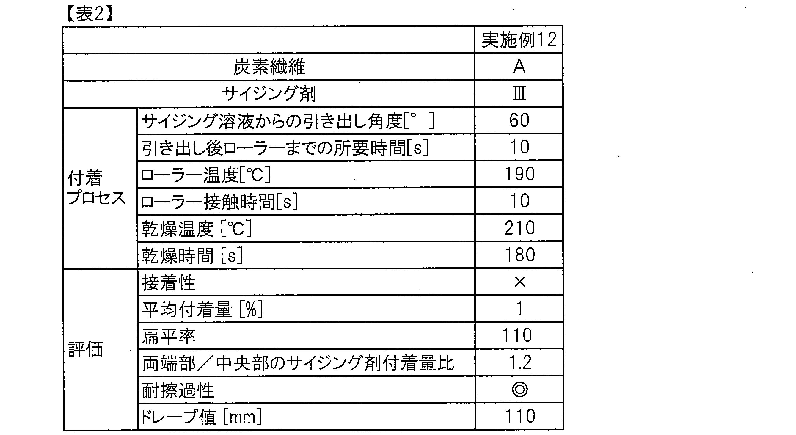
第Iの工程:炭素繊維束を製造する工程
実施例1と同様にした。
サイジング剤成分として(IV)を用い、溶媒に水を用いて表3に示す濃度でサイジング剤溶液を調合した。この水の沸点は100℃であった。このサイジング剤溶液を表面処理された炭素繊維束に浸漬した後、サイジング剤溶液の液面と炭素繊維束の成す角が60度となるようサイジング剤溶液から炭素繊維束を引き出し、ガイドローラーを介して炭素繊維束を走行させ10秒間経過した後、140℃に加熱したローラーに10秒間接触させた。その後さらに210℃の温度で180秒間熱処理をして、サイジング剤塗布炭素繊維束を得た。炭素繊維束に対するサイジング剤の平均付着量は上述の方法により測定し、表面処理された炭素繊維束100質量部に対して1質量部となるように調整した。
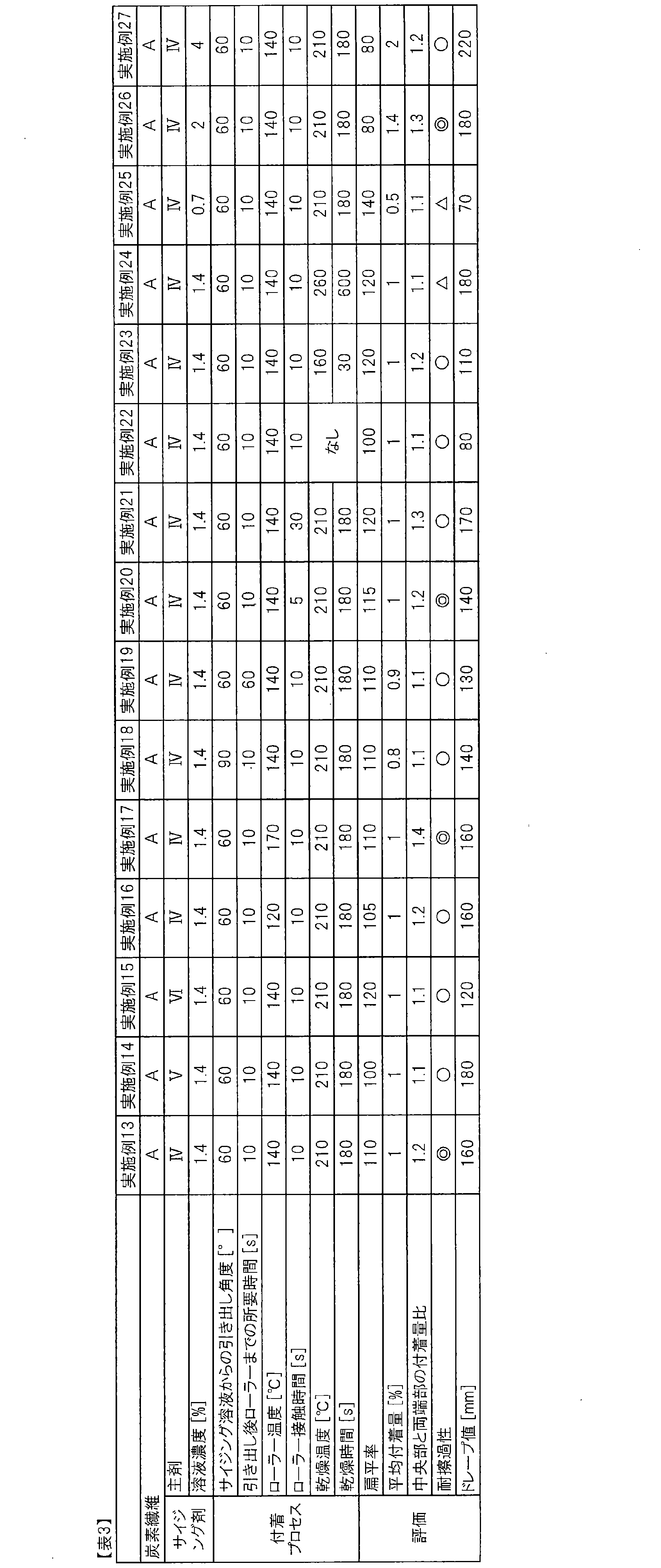
第Iの工程:原料となる炭素繊維束を製造する工程
実施例1と同様にした。
サイジング剤成分として(V)を用いた以外は、実施例13と同様の方法でサイジング剤塗布炭素繊維束を得た。
第Iの工程:原料となる炭素繊維束を製造する工程
実施例1と同様にした。
サイジング剤成分として(VI)を用いた以外は、実施例13と同様の方法でサイジング剤塗布炭素繊維束を得た。
第Iの工程:原料となる炭素繊維束を製造する工程
実施例1と同様にした。
加熱したローラーの温度を表3に記載の通りに変更した以外は、実施例13と同様の方法でサイジング剤塗布炭素繊維束を得た。
第Iの工程:原料となる炭素繊維束を製造する工程
実施例1と同様にした。
サイジング剤溶液を表面処理された炭素繊維束に浸漬した後、サイジング剤溶液の液面と炭素繊維束の成す角が90度となるようサイジング剤溶液から炭素繊維束を引き出した以外は、実施例13と同様の方法でサイジング剤塗布炭素繊維束を得た。
第Iの工程:原料となる炭素繊維束を製造する工程
実施例1と同様にした。
サイジング剤溶液から炭素繊維束を引き出した後、加熱したローラーに接触するまでガイドローラーを介して炭素繊維束を60秒間走行させた以外は、実施例13と同様の方法でサイジング剤塗布炭素繊維束を得た。
第Iの工程:原料となる炭素繊維束を製造する工程
実施例1と同様にした。
炭素繊維束を加熱したローラーに接触させる時間を5秒に変更した以外は、実施例13と同様の方法でサイジング剤塗布炭素繊維束を得た。
第Iの工程:原料となる炭素繊維束を製造する工程
実施例1と同様にした。
炭素繊維束を加熱したローラーに接触させる時間を30秒に変更した以外は、実施例13と同様の方法でサイジング剤塗布炭素繊維束を得た。
第Iの工程:原料となる炭素繊維束を製造する工程
実施例1と同様にした。
サイジング剤成分として(IV)を使用し、表面処理された炭素繊維束に浸漬した後、サイジング剤溶液の液面と炭素繊維束の成す角が60度となるようサイジング剤溶液から炭素繊維束を引き出し、ガイドローラーを介して炭素繊維束を走行させ10秒間経過した後、140℃に加熱したローラーに10秒間接触させ、サイジング剤塗布炭素繊維束を得た。
第Iの工程:原料となる炭素繊維束を製造する工程
実施例1と同様にした。
ローラーに接触した後の乾燥温度、乾燥時間を表3の通りに熱処理をした以外は実施例13と同様にしてサイジング剤塗布炭素繊維束を得た。
第Iの工程:原料となる炭素繊維束を製造する工程
実施例1と同様にした。
炭素繊維束に対するサイジング剤の平均付着量を、表3の通りに調整した以外は、実施例13と同様の方法でサイジング剤塗布炭素繊維束を得た。
(比較例1)
第Iの工程:原料となる炭素繊維束を製造する工程
実施例1と同様にした。
実施例1と同様にサイジング剤溶液を調合した。このサイジング剤溶液を表面処理された炭素繊維束に浸漬した後、サイジング剤溶液の液面と炭素繊維束の成す角が60度となるようサイジング剤溶液から炭素繊維束を引き出し、ガイドローラーを介して炭素繊維束を走行させ10秒間経過した後、80℃に加熱したローラーに3秒間接触させた。その後さらに210℃の温度で180秒間熱処理をして、サイジング剤塗布炭素繊維束を得た。炭素繊維束に対するサイジング剤の平均付着量は上述の方法により測定し、表面処理された炭素繊維100質量部に対して1質量部となるように調整した。
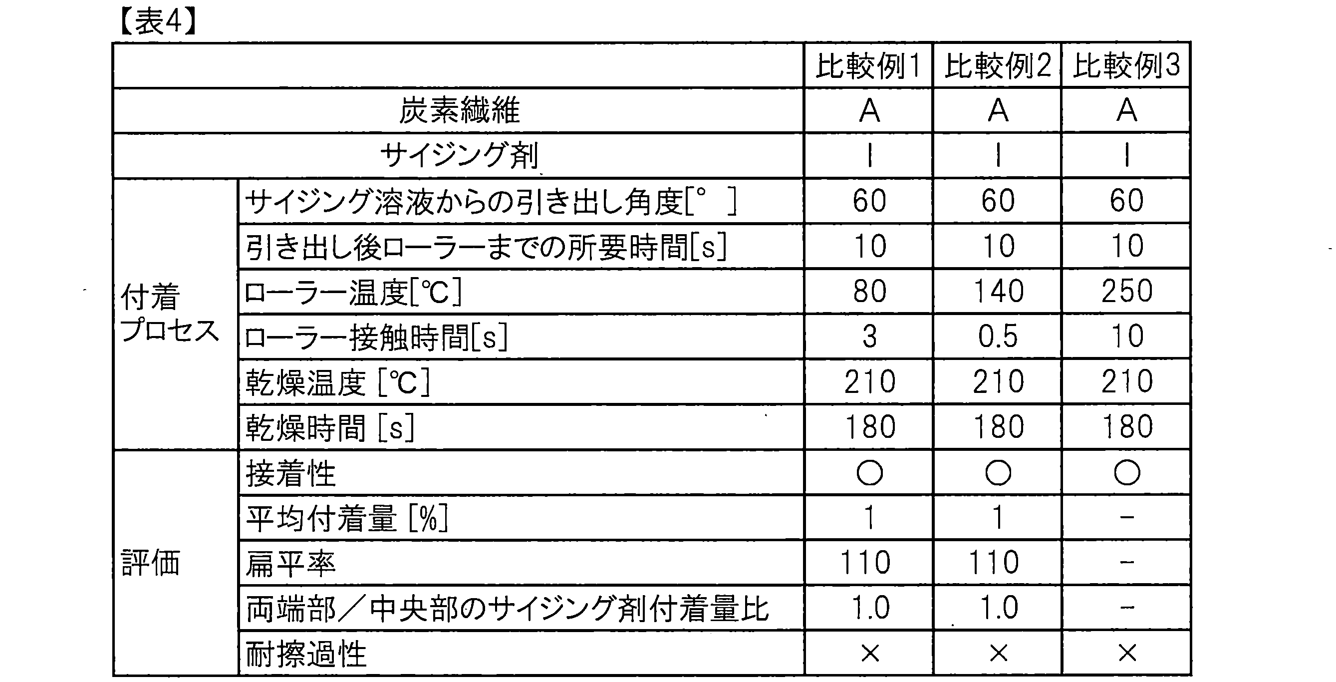
第Iの工程:原料となる炭素繊維束を製造する工程
実施例1と同様にした。
炭素繊維束を加熱したローラーに接触させる時間を0.5秒に変更した以外は、実施例1と同様の方法でサイジング剤塗布炭素繊維束を得た。
第Iの工程:原料となる炭素繊維束を製造する工程
実施例1と同様にした。
加熱したローラーの温度を250℃に変更した以外は、実施例1と同様の方法でサイジング剤塗布炭素繊維束を得た。
第Iの工程:原料となる炭素繊維束を製造する工程
実施例1と同様にした。
実施例13と同様にサイジング剤溶液を調合した。このサイジング剤溶液を表面処理された炭素繊維束に浸漬した後、サイジング剤溶液の液面と炭素繊維束の成す角が60度となるようサイジング剤溶液から炭素繊維束を引き出し、ガイドローラーを介して炭素繊維束を走行させ10秒間経過した後、80℃に加熱したローラーに5秒間接触させサイジング剤塗布炭素繊維束を得た。炭素繊維束に対するサイジング剤の平均付着量は上述の方法により測定し、表面処理された炭素繊維100質量部に対して1質量部となるように調整した。

第Iの工程:原料となる炭素繊維束を製造する工程
実施例1と同様にした。
炭素繊維束を加熱したローラーに接触させる時間を0.5秒に変更した以外は、実施例13と同様の方法でサイジング剤塗布炭素繊維束を得た。
第Iの工程:原料となる炭素繊維束を製造する工程
実施例1と同様にした。
実施例13の方法から加熱したローラーの温度を200℃に変更したところ、加熱したローラー上に固着した汚れにより、炭素繊維束が融着してしまい良好な炭素繊維束を得ることができなかった。
第Iの工程:原料となる炭素繊維束を製造する工程
実施例1と同様にした。
炭素繊維束を加熱したローラーに接触しない以外は、実施例13と同様の方法でサイジング剤塗布炭素繊維束を得た。
第Iの工程:原料となる炭素繊維束を製造する工程
実施例1と同様にした。
サイジング剤成分として(VII)を用いた以外は、実施例13と同様の方法でサイジング剤塗布炭素繊維束を得た。
第Iの工程:原料となる炭素繊維束を製造する工程
実施例1と同様にした。
サイジング剤成分として(VIII)を用いた以外は、実施例13と同様の方法でサイジング剤塗布炭素繊維束を得た。
Claims (16)
- (A)分子内にエポキシ基を2以上有するポリエーテル型脂肪族エポキシ化合物および/またはポリオール型脂肪族エポキシ化合物を含むサイジング剤、または、
(B)ガラス転移温度が-100℃以上50℃以下の非水溶性化合物を含むサイジング剤
が塗布された炭素繊維束であって、
炭素繊維束断面の扁平率(幅/厚さ)が10以上150以下であり、
炭素繊維束を繊維方向に沿って幅方向に質量で3等分した際に、両端部の各々における炭素繊維束の質量に対するサイジング剤の質量の比の平均値と、中央部における炭素繊維束の質量に対するサイジング剤の質量の比から算出される両端部/中央部のサイジング剤付着量比が1.05以上1.5以下であることを特徴とするサイジング剤塗布炭素繊維束。 - 前記サイジング剤が脂肪族エポキシ化合物(A)を含むものであって、脂肪族エポキシ化合物(A)が、グリセロール、ジグリセロール、ポリグリセロール、トリメチロールプロパン、ペンタエリスリトール、ソルビトール、およびアラビトールからなる群から選択される1種と、エピクロロヒドリンとの反応により得られるグリシジルエーテル型エポキシ化合物である、請求項1に記載のサイジング剤塗布炭素繊維束。
- 前記サイジング剤が非水溶性化合物(B)を含むものであって、非水溶性化合物(B)が芳香族化合物である請求項1に記載のサイジング剤塗布炭素繊維束。
- 前記サイジング剤が非水溶性化合物(B)を含むものであって、非水溶性化合物(B)がラテックス化合物である請求項1または3のいずれかに記載のサイジング剤塗布炭素繊維束。
- 炭素繊維束断面の扁平率(幅/厚さ)が90を超え150以下である請求項1~4のいずれかに記載のサイジング剤塗布炭素繊維束。
- 前記サイジング剤が非水溶性化合物(B)を含むものであって、ドレープ値が100mm以上200mm以下である請求項1、3~5のいずれかに記載のサイジング剤塗布炭素繊維束。
- サイジング剤の平均付着量が0.2質量%以上1.5質量%未満である請求項1~6のいずれかに記載のサイジング剤塗布炭素繊維束。
- 炭素繊維束のストランド引張強度が3.5GPa以上、ストランド引張弾性率が220GPa以上である請求項1~7のいずれかに記載のサイジング剤塗布炭素繊維束。
- 請求項1~8のいずれかに記載のサイジング剤塗布炭素繊維束を製造する方法であって、サイジング剤を含むサイジング剤溶液に炭素繊維束を含浸させた後、サイジング剤溶液の溶媒の沸点より10℃以上80℃以下高い温度範囲で加熱したローラーに1秒以上60秒以下の時間接触させることを特徴とするサイジング剤塗布炭素繊維束の製造方法。
- 炭素繊維束をサイジング剤溶液に含浸させた後、炭素繊維束をサイジング剤溶液から取り出す過程において、サイジング剤溶液の液面と炭素繊維束の成す角が20度以上70度以下である請求項9に記載のサイジング剤塗布炭素繊維束の製造方法。
- 前記サイジング剤が脂肪族エポキシ化合物(A)を含むものであって、炭素繊維束をサイジング剤溶液に含浸させた後、ローラーに接触するまでの時間が60秒以下である請求項9または10に記載のサイジング剤塗布炭素繊維束の製造方法。
- 前記サイジング剤が非水溶性化合物(B)を含むものであって、炭素繊維束をサイジング剤溶液に含浸させた後、ローラーに接触させるまでの時間が3秒以上30秒以下である請求項9または10に記載のサイジング剤塗布炭素繊維束の製造方法。
- 前記サイジング剤が非水溶性化合物(B)を含むものであって、炭素繊維束をローラーに接触させる工程の後、180℃以上240℃以下の温度範囲で30秒以上300秒以下の時間熱処理を行う請求項9、10、12のいずれかに記載のサイジング剤塗布炭素繊維束の製造方法。
- 請求項1~8のいずれかに記載のサイジング剤塗布炭素繊維束と、熱硬化性樹脂とを含むプリプレグ。
- 請求項14に記載のプリプレグを硬化させてなる炭素繊維強化複合材料。
- 請求項1~8のいずれかに記載のサイジング剤塗布炭素繊維束と、熱可塑性樹脂とを含む炭素繊維強化複合材料。
Priority Applications (7)
| Application Number | Priority Date | Filing Date | Title |
|---|---|---|---|
| US15/526,660 US10544275B2 (en) | 2015-01-21 | 2016-01-13 | Sizing agent coated carbon fiber bundle, method for manufacturing same, prepreg, and carbon fiber reinforced composite material |
| CN201680005357.6A CN107109773B (zh) | 2015-01-21 | 2016-01-13 | 涂上浆剂碳纤维束及其制造方法、预浸料坯及碳纤维增强复合材料 |
| JP2016512144A JP5967334B1 (ja) | 2015-01-21 | 2016-01-13 | サイジング剤塗布炭素繊維束およびその製造方法、プリプレグおよび炭素繊維強化複合材料 |
| MX2017006960A MX2017006960A (es) | 2015-01-21 | 2016-01-13 | Haz de fibras de carbono revestido con agente de encolado, metodo para la fabricacion del mismo, preimpregnado y material compuesto reforzado con fibra de carbono. |
| EP16740029.0A EP3208376B1 (en) | 2015-01-21 | 2016-01-13 | Sizing agent-coated carbon fiber bundle, method for manufacturing same, prepreg, and carbon fiber-reinforced composite material |
| KR1020177012713A KR101770661B1 (ko) | 2015-01-21 | 2016-01-13 | 사이징제 도포 탄소 섬유 다발 및 그 제조 방법, 프리프레그 및 탄소 섬유 강화 복합 재료 |
| US16/705,353 US11390720B2 (en) | 2015-01-21 | 2019-12-06 | Sizing agent coated carbon fiber bundle, method for manufacturing same, prepreg, and carbon fiber reinforced composite material |
Applications Claiming Priority (4)
| Application Number | Priority Date | Filing Date | Title |
|---|---|---|---|
| JP2015009121 | 2015-01-21 | ||
| JP2015-009121 | 2015-01-21 | ||
| JP2015-045598 | 2015-03-09 | ||
| JP2015045598 | 2015-03-09 |
Related Child Applications (2)
| Application Number | Title | Priority Date | Filing Date |
|---|---|---|---|
| US15/526,660 A-371-Of-International US10544275B2 (en) | 2015-01-21 | 2016-01-13 | Sizing agent coated carbon fiber bundle, method for manufacturing same, prepreg, and carbon fiber reinforced composite material |
| US16/705,353 Continuation US11390720B2 (en) | 2015-01-21 | 2019-12-06 | Sizing agent coated carbon fiber bundle, method for manufacturing same, prepreg, and carbon fiber reinforced composite material |
Publications (1)
| Publication Number | Publication Date |
|---|---|
| WO2016117422A1 true WO2016117422A1 (ja) | 2016-07-28 |
Family
ID=56416969
Family Applications (1)
| Application Number | Title | Priority Date | Filing Date |
|---|---|---|---|
| PCT/JP2016/050777 Ceased WO2016117422A1 (ja) | 2015-01-21 | 2016-01-13 | サイジング剤塗布炭素繊維束およびその製造方法、プリプレグおよび炭素繊維強化複合材料 |
Country Status (8)
| Country | Link |
|---|---|
| US (2) | US10544275B2 (ja) |
| EP (1) | EP3208376B1 (ja) |
| JP (1) | JP5967334B1 (ja) |
| KR (1) | KR101770661B1 (ja) |
| CN (1) | CN107109773B (ja) |
| MX (1) | MX2017006960A (ja) |
| TW (1) | TWI598380B (ja) |
| WO (1) | WO2016117422A1 (ja) |
Cited By (3)
| Publication number | Priority date | Publication date | Assignee | Title |
|---|---|---|---|---|
| US20200347522A1 (en) * | 2018-01-26 | 2020-11-05 | Toray Industries, Inc. | Reinforcing fiber bundle |
| CN112726208A (zh) * | 2019-10-28 | 2021-04-30 | 赵程 | 一种耐磨防水的复合碳纤维布及其制备方法 |
| JP2023008888A (ja) * | 2021-06-28 | 2023-01-19 | 臺灣塑膠工業股▲ふん▼有限公司 | サイジング剤組成物、炭素繊維材料及び複合材料 |
Families Citing this family (11)
| Publication number | Priority date | Publication date | Assignee | Title |
|---|---|---|---|---|
| HUE039417T2 (hu) * | 2013-03-06 | 2018-12-28 | Sumitomo Seika Chemicals | Szálkezelõ készítmény, a szálkezelõ készítménnyel kezelt szénszálak és a szénszálakat tartalmazó kompozit anyag |
| JP7350745B2 (ja) * | 2018-08-02 | 2023-09-26 | 三洋化成工業株式会社 | 繊維用集束剤組成物、繊維束、繊維製品及び複合材料 |
| CN112048854B (zh) * | 2020-09-11 | 2021-05-11 | 江苏恒神股份有限公司 | 缠绕成型用碳纤维束及其制备方法和应用 |
| CN112210192B (zh) * | 2020-10-30 | 2022-06-10 | 大连交通大学 | 一种碳纤维复合材料、无人机机翼及其制备方法 |
| US12053908B2 (en) | 2021-02-01 | 2024-08-06 | Regen Fiber, Llc | Method and system for recycling wind turbine blades |
| TWI784693B (zh) * | 2021-08-27 | 2022-11-21 | 臺灣塑膠工業股份有限公司 | 用於碳纖維的上漿劑 |
| US20230087214A1 (en) * | 2021-09-22 | 2023-03-23 | Hao-Chia WU | Method for splitting carbon fiber tow |
| JP2024113718A (ja) * | 2023-02-10 | 2024-08-23 | ヤンマーホールディングス株式会社 | 作業機械の制御方法、作業機械用制御プログラム、作業機械用制御システム及び作業機械 |
| KR102741905B1 (ko) * | 2024-06-25 | 2024-12-16 | 문규상 | 원사의 가공 방법 |
| CN120192017B (zh) * | 2025-05-23 | 2025-08-19 | 皖创环保股份有限公司 | 一种基于碳纤维填料的微生物强化水处理方法 |
| CN121181948B (zh) * | 2025-11-24 | 2026-02-03 | 苏州实验室 | 一种用于航空航天低温贮箱的碳纤维增强复合材料及其制备方法 |
Citations (5)
| Publication number | Priority date | Publication date | Assignee | Title |
|---|---|---|---|---|
| JPH079444A (ja) * | 1993-06-28 | 1995-01-13 | Toray Ind Inc | 炭素繊維束およびプリプレグ |
| JP2003336129A (ja) * | 2002-05-14 | 2003-11-28 | Toho Tenax Co Ltd | 炭素繊維ストランド |
| JP2008095222A (ja) * | 2006-10-10 | 2008-04-24 | Toray Ind Inc | 炭素繊維束およびプリプレグ |
| JP2009191425A (ja) * | 2008-02-18 | 2009-08-27 | Mitsubishi Rayon Co Ltd | 炭素繊維の製造方法 |
| CN104195766A (zh) * | 2014-09-05 | 2014-12-10 | 中复神鹰碳纤维有限责任公司 | 一种碳纤维上浆后的干燥方法 |
Family Cites Families (22)
| Publication number | Priority date | Publication date | Assignee | Title |
|---|---|---|---|---|
| US3957716A (en) | 1973-10-01 | 1976-05-18 | Hercules Incorporated | Sized carbon fibers |
| JP2001271230A (ja) | 2000-03-23 | 2001-10-02 | Mitsubishi Rayon Co Ltd | 炭素繊維チョップドストランド及びその製造方法 |
| JP2002294568A (ja) * | 2001-03-30 | 2002-10-09 | Toho Tenax Co Ltd | フィラメントワインディング用炭素繊維束 |
| JP2002317382A (ja) * | 2001-04-25 | 2002-10-31 | Toho Tenax Co Ltd | 織物用炭素繊維束 |
| JP2004149981A (ja) * | 2002-10-31 | 2004-05-27 | Toho Tenax Co Ltd | 炭素繊維ストランド及びその製造法 |
| KR20050071371A (ko) * | 2002-10-31 | 2005-07-07 | 도호 테낙구스 가부시키가이샤 | 탄소 섬유 스트랜드 |
| WO2005012604A2 (ja) * | 2003-07-31 | 2005-02-10 | Mitsubishi Rayon Co., Ltd. | 炭素繊維束及びその製造方法、並びに熱可塑性樹脂組成物及びその成形品 |
| US7680092B2 (en) * | 2004-02-19 | 2010-03-16 | Rockwell Collins, Inc. | Link adaption for mobile ad hoc and mesh networks |
| JP4468790B2 (ja) | 2004-11-18 | 2010-05-26 | 日本バイリーン株式会社 | 不織布、電気二重層キャパシタ用セパレータ、リチウムイオン二次電池用セパレータ、電気二重層キャパシタ及びリチウムイオン二次電池 |
| JP2006144168A (ja) | 2004-11-19 | 2006-06-08 | Toray Ind Inc | 炭素繊維束 |
| JP5054906B2 (ja) * | 2005-09-09 | 2012-10-24 | 東レ株式会社 | コンクリートもしくはモルタル補強用炭素繊維複合樹脂線材、その製造方法およびコンクリートもしくはモルタル構造物 |
| US7724284B2 (en) * | 2005-09-29 | 2010-05-25 | Aptina Imaging Corporation | Multi-camera system and method having a common processing block |
| JPWO2007060833A1 (ja) * | 2005-11-25 | 2009-05-07 | 東レ株式会社 | 炭素繊維束、プリプレグおよび炭素繊維強化複合材料 |
| JP2009242964A (ja) | 2008-03-29 | 2009-10-22 | Toho Tenax Co Ltd | 炭素繊維及びその製造方法 |
| EP2589701B1 (en) * | 2010-06-30 | 2019-08-21 | Toray Industries, Inc. | Method for producing sizing agent-coated carbon fibers, and sizing agent-coated carbon fibers |
| JP5870526B2 (ja) * | 2011-07-21 | 2016-03-01 | 三菱レイヨン株式会社 | サイジング剤液含浸炭素繊維束の製造方法 |
| US9862824B2 (en) * | 2011-08-22 | 2018-01-09 | Mitsubishi Chemical Corporation | Carbon fiber sizing agent, aqueous dispersion thereof, carbon fiber bundle applied with sizing agent, sheet-like article comprising carbon fiber bundle, and carbon fiber reinforced composite material |
| JP5960402B2 (ja) | 2011-09-08 | 2016-08-02 | 東邦テナックス株式会社 | 炭素繊維束及び炭素繊維束の製造方法 |
| US9506169B2 (en) * | 2012-03-09 | 2016-11-29 | Teijin Limited | Carbon fiber bundle and manufacturing method of the same |
| KR101532194B1 (ko) | 2012-07-25 | 2015-07-15 | 도레이 카부시키가이샤 | 프리프레그 및 탄소 섬유 강화 복합 재료 |
| EP2910676B1 (en) * | 2012-10-18 | 2017-10-04 | Toray Industries, Inc. | Carbon fiber-reinforced resin composition, method for manufacturing carbon fiber-reinforced resin composition, molding material, method for manufacturing molding material, and carbon-fiber reinforced resin molded article |
| JP5516771B1 (ja) | 2013-01-29 | 2014-06-11 | 東レ株式会社 | プリプレグ、プリプレグの製造方法および炭素繊維強化複合材料 |
-
2016
- 2016-01-13 CN CN201680005357.6A patent/CN107109773B/zh active Active
- 2016-01-13 KR KR1020177012713A patent/KR101770661B1/ko active Active
- 2016-01-13 US US15/526,660 patent/US10544275B2/en active Active
- 2016-01-13 MX MX2017006960A patent/MX2017006960A/es unknown
- 2016-01-13 WO PCT/JP2016/050777 patent/WO2016117422A1/ja not_active Ceased
- 2016-01-13 JP JP2016512144A patent/JP5967334B1/ja active Active
- 2016-01-13 EP EP16740029.0A patent/EP3208376B1/en active Active
- 2016-01-19 TW TW105101469A patent/TWI598380B/zh active
-
2019
- 2019-12-06 US US16/705,353 patent/US11390720B2/en active Active
Patent Citations (5)
| Publication number | Priority date | Publication date | Assignee | Title |
|---|---|---|---|---|
| JPH079444A (ja) * | 1993-06-28 | 1995-01-13 | Toray Ind Inc | 炭素繊維束およびプリプレグ |
| JP2003336129A (ja) * | 2002-05-14 | 2003-11-28 | Toho Tenax Co Ltd | 炭素繊維ストランド |
| JP2008095222A (ja) * | 2006-10-10 | 2008-04-24 | Toray Ind Inc | 炭素繊維束およびプリプレグ |
| JP2009191425A (ja) * | 2008-02-18 | 2009-08-27 | Mitsubishi Rayon Co Ltd | 炭素繊維の製造方法 |
| CN104195766A (zh) * | 2014-09-05 | 2014-12-10 | 中复神鹰碳纤维有限责任公司 | 一种碳纤维上浆后的干燥方法 |
Non-Patent Citations (1)
| Title |
|---|
| See also references of EP3208376A4 * |
Cited By (6)
| Publication number | Priority date | Publication date | Assignee | Title |
|---|---|---|---|---|
| US20200347522A1 (en) * | 2018-01-26 | 2020-11-05 | Toray Industries, Inc. | Reinforcing fiber bundle |
| US12037717B2 (en) * | 2018-01-26 | 2024-07-16 | Toray Industries, Inc. | Reinforcing fiber bundle |
| CN112726208A (zh) * | 2019-10-28 | 2021-04-30 | 赵程 | 一种耐磨防水的复合碳纤维布及其制备方法 |
| CN112726208B (zh) * | 2019-10-28 | 2022-09-09 | 赵程 | 一种耐磨防水的复合碳纤维布及其制备方法 |
| JP2023008888A (ja) * | 2021-06-28 | 2023-01-19 | 臺灣塑膠工業股▲ふん▼有限公司 | サイジング剤組成物、炭素繊維材料及び複合材料 |
| JP7425833B2 (ja) | 2021-06-28 | 2024-01-31 | 臺灣塑膠工業股▲ふん▼有限公司 | サイジング剤組成物、炭素繊維材料及び複合材料 |
Also Published As
| Publication number | Publication date |
|---|---|
| EP3208376A4 (en) | 2017-11-08 |
| CN107109773A (zh) | 2017-08-29 |
| TWI598380B (zh) | 2017-09-11 |
| EP3208376B1 (en) | 2022-08-03 |
| KR101770661B1 (ko) | 2017-08-23 |
| US20200165400A1 (en) | 2020-05-28 |
| JPWO2016117422A1 (ja) | 2017-04-27 |
| TW201638163A (zh) | 2016-11-01 |
| US11390720B2 (en) | 2022-07-19 |
| JP5967334B1 (ja) | 2016-08-10 |
| EP3208376A1 (en) | 2017-08-23 |
| CN107109773B (zh) | 2018-05-11 |
| US10544275B2 (en) | 2020-01-28 |
| US20170349720A1 (en) | 2017-12-07 |
| KR20170059482A (ko) | 2017-05-30 |
| MX2017006960A (es) | 2017-08-10 |
Similar Documents
| Publication | Publication Date | Title |
|---|---|---|
| JP5967334B1 (ja) | サイジング剤塗布炭素繊維束およびその製造方法、プリプレグおよび炭素繊維強化複合材料 | |
| JP6179591B2 (ja) | サイジング剤塗布強化繊維、サイジング剤塗布強化繊維の製造方法、プリプレグおよび繊維強化複合材料 | |
| JP5477312B2 (ja) | サイジング剤塗布炭素繊維束およびその製造方法 | |
| CN107249697B (zh) | 碳纤维增强复合材料制管状体及高尔夫球杆杆身 | |
| US20150247025A1 (en) | Carbon fiber-reinforced resin composition, method for manufacturing carbon fiber-reinforced resin composition, molding material, method for manufacturing molding material, and carbon fiber-reinforced resin molded article | |
| JP2017119936A (ja) | サイジング剤塗布炭素繊維、サイジング剤塗布炭素繊維の製造方法、プリプレグおよび炭素繊維強化複合材料 | |
| WO2016143371A1 (ja) | サイジング剤塗布炭素繊維、サイジング剤塗布炭素繊維の製造方法、炭素繊維強化複合材料および炭素繊維強化複合材料の製造方法 | |
| JP6056517B2 (ja) | サイジング剤塗布炭素繊維、サイジング剤塗布炭素繊維の製造方法、およびプリプレグならびに炭素繊維強化熱可塑性樹脂組成物 | |
| JP2017048481A (ja) | サイジング剤塗布強化繊維、サイジング剤塗布強化繊維の製造方法、プリプレグおよび繊維強化複合材料 | |
| JP5516771B1 (ja) | プリプレグ、プリプレグの製造方法および炭素繊維強化複合材料 | |
| JP6394085B2 (ja) | サイジング剤塗布炭素繊維およびその製造方法、プリプレグおよび炭素繊維強化複合材料 | |
| JP5516769B1 (ja) | 成形材料、成形材料の製造方法および炭素繊維強化複合材料 | |
| JP2017155372A (ja) | サイジング剤塗布炭素繊維、サイジング剤塗布炭素繊維の製造方法、プリプレグおよび炭素繊維強化複合材料 | |
| JP5516770B1 (ja) | 成形材料、成形材料の製造方法および炭素繊維強化複合材料 | |
| JP5454668B1 (ja) | 炭素繊維強化熱可塑性樹脂組成物および成形品 | |
| JP4924768B2 (ja) | サイジング剤塗布炭素繊維の製造方法 | |
| JP5967333B1 (ja) | サイジング剤塗布炭素繊維、サイジング剤塗布炭素繊維の製造方法、炭素繊維強化複合材料および炭素繊維強化複合材料の製造方法 | |
| JP4924769B1 (ja) | サイジング剤塗布炭素繊維の製造方法 |
Legal Events
| Date | Code | Title | Description |
|---|---|---|---|
| ENP | Entry into the national phase |
Ref document number: 2016512144 Country of ref document: JP Kind code of ref document: A |
|
| 121 | Ep: the epo has been informed by wipo that ep was designated in this application |
Ref document number: 16740029 Country of ref document: EP Kind code of ref document: A1 |
|
| ENP | Entry into the national phase |
Ref document number: 20177012713 Country of ref document: KR Kind code of ref document: A |
|
| WWE | Wipo information: entry into national phase |
Ref document number: 15526660 Country of ref document: US |
|
| REEP | Request for entry into the european phase |
Ref document number: 2016740029 Country of ref document: EP |
|
| WWE | Wipo information: entry into national phase |
Ref document number: MX/A/2017/006960 Country of ref document: MX |
|
| NENP | Non-entry into the national phase |
Ref country code: DE |