WO2016117423A1 - シート用パッド - Google Patents
シート用パッド Download PDFInfo
- Publication number
- WO2016117423A1 WO2016117423A1 PCT/JP2016/050782 JP2016050782W WO2016117423A1 WO 2016117423 A1 WO2016117423 A1 WO 2016117423A1 JP 2016050782 W JP2016050782 W JP 2016050782W WO 2016117423 A1 WO2016117423 A1 WO 2016117423A1
- Authority
- WO
- WIPO (PCT)
- Prior art keywords
- groove
- pressure receiving
- additional
- partition
- receiving region
- Prior art date
- Legal status (The legal status is an assumption and is not a legal conclusion. Google has not performed a legal analysis and makes no representation as to the accuracy of the status listed.)
- Ceased
Links
Images

Classifications
-
- B—PERFORMING OPERATIONS; TRANSPORTING
- B60—VEHICLES IN GENERAL
- B60N—SEATS SPECIALLY ADAPTED FOR VEHICLES; VEHICLE PASSENGER ACCOMMODATION NOT OTHERWISE PROVIDED FOR
- B60N2/00—Seats specially adapted for vehicles; Arrangement or mounting of seats in vehicles
- B60N2/70—Upholstery springs ; Upholstery
- B60N2/7017—Upholstery springs ; Upholstery characterised by the manufacturing process; manufacturing upholstery or upholstery springs not otherwise provided for
-
- B—PERFORMING OPERATIONS; TRANSPORTING
- B60—VEHICLES IN GENERAL
- B60N—SEATS SPECIALLY ADAPTED FOR VEHICLES; VEHICLE PASSENGER ACCOMMODATION NOT OTHERWISE PROVIDED FOR
- B60N2/00—Seats specially adapted for vehicles; Arrangement or mounting of seats in vehicles
- B60N2/70—Upholstery springs ; Upholstery
-
- A—HUMAN NECESSITIES
- A47—FURNITURE; DOMESTIC ARTICLES OR APPLIANCES; COFFEE MILLS; SPICE MILLS; SUCTION CLEANERS IN GENERAL
- A47C—CHAIRS; SOFAS; BEDS
- A47C27/00—Spring, stuffed or fluid mattresses or cushions specially adapted for chairs, beds or sofas
- A47C27/14—Spring, stuffed or fluid mattresses or cushions specially adapted for chairs, beds or sofas with foamed material inlays
-
- A—HUMAN NECESSITIES
- A47—FURNITURE; DOMESTIC ARTICLES OR APPLIANCES; COFFEE MILLS; SPICE MILLS; SUCTION CLEANERS IN GENERAL
- A47C—CHAIRS; SOFAS; BEDS
- A47C7/00—Parts, details, or accessories of chairs or stools
- A47C7/02—Seat parts
- A47C7/18—Seat parts having foamed material included in cushioning part
-
- A—HUMAN NECESSITIES
- A47—FURNITURE; DOMESTIC ARTICLES OR APPLIANCES; COFFEE MILLS; SPICE MILLS; SUCTION CLEANERS IN GENERAL
- A47C—CHAIRS; SOFAS; BEDS
- A47C7/00—Parts, details, or accessories of chairs or stools
- A47C7/02—Seat parts
- A47C7/18—Seat parts having foamed material included in cushioning part
- A47C7/20—Seat parts having foamed material included in cushioning part with reinforcement in the foam layer
-
- B—PERFORMING OPERATIONS; TRANSPORTING
- B60—VEHICLES IN GENERAL
- B60N—SEATS SPECIALLY ADAPTED FOR VEHICLES; VEHICLE PASSENGER ACCOMMODATION NOT OTHERWISE PROVIDED FOR
- B60N2/00—Seats specially adapted for vehicles; Arrangement or mounting of seats in vehicles
- B60N2/64—Back-rests or cushions
Definitions
- the present invention relates to a seat pad formed of a foamed molded body and provided with an occupant contact surface.
- This application claims priority based on Japanese Patent Application No. 2015-7648 for which it applied to Japan on January 19, 2015, and uses the content here.
- the present invention has been made in view of the above-described circumstances, and an object thereof is to achieve both durability and fit of a seat pad.
- seat which concerns on this invention is formed with a foaming molding.
- an occupant contact surface formed in a rectangular shape that is long in the longitudinal direction and short in the lateral direction is provided.
- the occupant abutment surface includes a main pressure receiving area where the occupant's buttocks or lumbar region abuts, and a sub pressure receiving area adjacent to the main pressure receiving area in the longitudinal direction.
- the occupant contact surface is provided with a partition groove extending in the longitudinal direction and arranged over the main pressure receiving area and the sub pressure receiving area. A plurality of the partition grooves are arranged in parallel in the lateral direction.
- An additional groove is formed on the bottom surface of the partition groove.
- the first portion located in the main pressure receiving region is a ratio of the volume of the additional groove per unit area of the bottom surface of the partition groove compared to the second portion located in the sub pressure receiving region.
- the average volume is small.
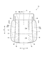
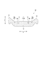
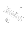
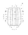
- FIG. 2 is a cross-sectional view taken along the line II-II shown in FIG. It is an expansion perspective view of the principal part of the pad for sheets shown in FIG.
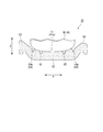
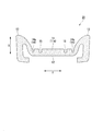
- FIG. 2 is a view showing a state in which an occupant is in contact with an occupant contact surface in the seat pad shown in FIG. 1, and showing a cross-section corresponding to the cross-sectional view taken along the line II-II shown in FIG.
- FIG. 6 is a cross-sectional view taken along arrow VI-VI shown in FIG. 5.
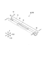
- FIG. 6 is a view showing a state in which an occupant is in contact with an occupant contact surface in the seat pad shown in FIG. 5, and is a view corresponding to a cross-sectional view taken along the line VI-VI in FIG. 5. It is an expansion perspective view of the principal part of the pad for sheets concerning one modification of the present invention.
- the sheet pad 10 is formed of a foam molded body.
- the foam molded article include a soft resin foam molded article obtained by foaming a resin material, such as a flexible polyurethane foam (soft resin).
- the sheet pad 10 is integrally formed of the same material.
- the seat pad 10 is employed, for example, in a seat (seat) attached to an automobile (vehicle).
- the seat pad 10 is provided with an occupant abutment surface 11 against which an occupant H seated on the seat abuts.
- a cushion pad is employed as the seat pad 10.
- the occupant contact surface 11 faces upward in the vertical direction Z. The load of the occupant H acts on the seat pad 10 from above.
- the sheet pad 10 includes a main body portion 12 and a peripheral edge portion 13 formed along the outer peripheral edge of the main body portion 12.
- the main body 12 is formed in a rectangular shape in plan view of the seat pad 10.
- the pair of sides of the rectangle extend along the front-rear direction X of the automobile, and the remaining pair of sides extend along the left-right direction Y of the automobile.
- the peripheral edge portion 13 is provided continuously over the respective outer peripheral edges of the main body portion 12 located on both sides in the left-right direction Y and on the rear side.
- the peripheral edge portion 13 is not provided in a portion located on the front side of the outer peripheral edge of the main body portion 12.
- the peripheral edge portion 13 exposes the main body portion 12 toward the front side.
- the peripheral edge 13 protrudes upward from the main body 12.
- the main body portion 12 and the peripheral edge portion 13 are partitioned by a valley line portion 14.
- the valley line portion 14 includes a pair of first valley line portions 14 a extending in the front-rear direction X and a second valley line portion 14 b extending in the left-right direction Y.
- the first valley line portion 14a is formed in a concave groove shape.
- the 2nd trough line part 14b has connected the parts located in the back side in a pair of 1st trough line part 14a.
- the valley line portion 14 is formed symmetrically in the left-right direction Y with respect to the reference line L in the plan view of the sheet pad 10.
- the reference line L passes through a central portion in the left-right direction Y of the seat pad 10 in a plan view of the seat pad 10.
- the passenger contact surface 11 is formed by the upper surface of the main body portion 12 and the upper surface of the peripheral edge portion 13.
- the occupant contact surface 11 is formed in a rectangular shape that is long in the front-rear direction X (longitudinal direction) and short in the left-right direction Y (short direction) in the plan view of the seat pad 10.
- a pair of sides of the rectangle extend in the front-rear direction X, and the remaining pair of sides extend in the left-right direction Y.
- the entire occupant contact surface 11 is formed in a rectangular shape that is long in the front-rear direction X in the plan view of the seat pad 10.
- a portion of the occupant contact surface 11 formed by the main body portion 12 (hereinafter referred to as “the central portion of the occupant contact surface 11”) is also in the front-rear direction X in the plan view of the seat pad 10. It is formed in a long rectangular shape.
- crew contact surface 11 can be formed in planar shape.
- a center portion of the occupant abutment surface 11 includes a main pressure receiving region 11a where the heel portion H1 of the occupant H abuts, a sub pressure receiving region 11b adjacent to the main pressure receiving region 11a in the front-rear direction X, and the thigh of the occupant H abuts. It has.
- the main pressure receiving area 11a is more susceptible to damage due to a larger load than the sub pressure receiving area 11b.
- the main pressure receiving region 11a is a portion located on the rear side (the main pressure receiving region side along the longitudinal direction) in the center of the occupant contact surface 11.
- the sub pressure receiving region 11b is a portion located on the front side (sub pressure receiving region side along the longitudinal direction) in the center of the passenger contact surface 11.
- the main pressure receiving region 11a is larger in the front-rear direction X than the sub pressure receiving region 11b.
- the ratio of the size in the front-rear direction X between the main pressure receiving region 11a and the sub pressure receiving region 11b is, for example, about 6: 4.
- the main pressure receiving area 11a and the sub pressure receiving area 11b may be partitioned by, for example, a partition line (not shown) extending in the left-right direction Y.
- a partition line a ridgeline, a trough line (concave groove), etc. are employable, for example.
- a plurality of partition grooves 15 extending in a straight line are arranged in parallel on the passenger contact surface 11.
- the plurality of partition grooves 15 are arranged at the center of the occupant contact surface 11.
- the plurality of partition grooves 15 have the same shape and the same size.
- the partition groove 15 extends in the front-rear direction X and is disposed across the main pressure receiving region 11a and the sub pressure receiving region 11b.
- a portion located in the main pressure receiving region 11 a is larger in the front-rear direction X than a portion located in the sub pressure receiving region 11 b.
- the partition groove 15 is smaller in the front-rear direction X than the first valley line portion 14a.
- a pair of partitioning grooves 15 are arranged at intervals in the left-right direction Y.
- the pair of partition grooves 15 are formed symmetrically in the left-right direction Y with respect to the reference line L in the plan view of the sheet pad 10.
- channel 15 can be made equivalent to the distance between passenger
- the interval can be specifically about 150 to 250 mm, more specifically about 200 mm.
- the groove width of the partition groove 15 is the same over the entire length.
- the partition groove 15 is formed in a rectangular shape that is long in the front-rear direction X in the plan view of the seat pad 10. Further, as shown in FIG. 2, the groove width of the partition groove 15 is the same regardless of the position in the vertical direction Z.
- the partition groove 15 has a rectangular shape that is long in the vertical direction Z in a cross-sectional view along the left-right direction Y of the sheet pad 10.
- the side surface of the partition groove 15 is formed in a planar shape.
- the groove width of the partition groove 15 is, for example, about 3 to 20 mm.
- the groove width of the partition groove 15 may be gradually narrowed from the upper side to the lower side in the vertical direction Z, for example.
- a first chamfered portion 15 a is formed on the side surface of the partition groove 15 at the edge portion that forms the opening surface of the partition groove 15.
- the first chamfered portion 15 a is formed in a protruding curved surface shape having a curvature radius r in a cross-sectional view along the left-right direction Y of the seat pad 10.
- the radius of curvature r can be about 1 mm to 20 mm, for example.
- the depth of the partition groove 15 is the same over the entire area.
- the bottom surface of the partition groove 15 is formed in a planar shape.
- a second chamfered portion 15b is formed at a portion where the bottom surface and the side surface of the partition groove 15 are connected.
- the second chamfered portion 15b is formed in a concave curved surface shape in a cross-sectional view along the left-right direction Y of the sheet pad 10.
- an additional groove 16 is formed on the bottom surface of the partition groove 15.
- a plurality of additional grooves 16 are provided on the bottom surface of the partition groove 15 at intervals in the front-rear direction X.
- the groove width of the additional groove 16 is equal over the entire length.
- the additional groove 16 is formed in a rectangular shape that is long in the front-rear direction X in the plan view of the seat pad 10.
- the groove width of the additional groove 16 is equal to the groove width of the partition groove 15.
- the side surface of the partition groove 15 and the side surface of the additional groove 16 are formed flush with each other.
- the size of the additional groove 16 in the front-rear direction X is larger than the distance in the front-rear direction X between the additional grooves 16 adjacent to each other in the front-rear direction X.
- the additional groove 16 is gradually formed deeper from both ends along the front-rear direction X toward the center.
- the bottom surface of the additional groove 16 is formed in a concave curved surface when the additional groove 16 is viewed from the outside in the left-right direction Y.
- the depth D1 of the additional groove 16 is equal to or smaller than the depth D2 of the partition groove 15.
- the sum of the depth D1 of the additional groove 16 and the depth D2 of the partition groove 15 is, for example, about 50 to 90% of the thickness of the main body 12.
- the sum is the total depth D3 from the opening surface of the partition groove 15 to the bottom surface of the additional groove 16.
- the average volume is small.
- the area A1 of the bottom surface of the first portion 17 is larger than the area A2 of the bottom surface of the second portion 18.
- the total volume V1 of the additional groove 16 (additional groove 16 formed on the bottom surface of the first portion 17) located in the main pressure receiving region 11a is equal to the additional groove 16 (second portion 18) located in the sub pressure receiving region 11b. Is smaller than the total sum V2 of the volumes of the additional grooves 16) formed on the bottom surface.
- the average volume V1 / A1 in the first portion 17 is smaller than the average volume V2 / A2 in the second portion 18.
- the average volume V1 / A1 and V2 / A2 are obtained, when the unit area of the bottom surface of the partition groove 15 is 1 mm 2 and the unit of the volume of the additional groove 16 is mm 3 , the average volume V1 / A1 , V2 / A2 can be obtained in units of mm 3 / mm 2 .
- the average volume V2 / A2 in the second portion 18 is 2.0 to 6.0 (mm 3 / mm 2 ) larger than the average volume V1 / A1 in the first portion 17.
- the volume increases from the additional groove 16 located on the rear side toward the additional groove 16 located on the front side.
- the length along the front-rear direction X and the groove width along the left-right direction Y are equal to each other, and the depths along the vertical direction Z are different from each other.
- the plurality of additional grooves 16 are deeper from the additional groove 16 located on the rear side toward the additional groove 16 located on the front side.
- the volume of the additional groove 16 is adjusted by changing the depth of the additional groove 16.
- the heel portion H ⁇ b> 1 of the occupant H abuts on the main pressure receiving region 11 a of the occupant abutment surface 11.
- the thigh is in contact with the auxiliary pressure receiving region 11b. Accordingly, a large load acts on the main pressure receiving area 11a of the occupant contact surface 11, while a small load acts on the sub pressure receiving area 11b.
- the compressive deformation of the seat pad 10 causes a tensile stress to act in a direction along the occupant contact surface 11 starting from the most sinking portion of the occupant contact surface 11. If this tensile stress is not relieved, the portion where the tensile stress acts on the occupant contact surface 11 is stretched and the shape of this portion is restricted, which may affect the fit.
- the plurality of partition grooves 15 are arranged in parallel to the occupant contact surface 11 to partition the seat pad 10 into a plurality.
- An additional groove 16 is formed on the bottom surface of the partition groove 15. Therefore, the depth of the partition groove 15 can be partially increased to enhance the tensile stress relaxation effect. In addition, it is possible to suppress a decrease in strength (durability) of the sheet pad 10 as compared with the case where the partition groove 15 is formed deeply over the entire region. From the above, it is possible to achieve both durability and fit of the seat pad 10.
- the first portion 17 has a smaller average volume than the second portion 18. Therefore, it is possible to suppress an excessive decrease in strength due to the formation of the additional groove 16 in the main pressure receiving region 11a.
- the average volume is larger in the second portion 18 than in the first portion 17. Therefore, the fit of the seat pad 10 as a whole can be improved. From the above, the durability and fit of the seat pad 10 can be reliably achieved. Further, the average volume of the second portion 18 is 2.0 to 6.0 (mm 3 / mm 2 ) larger than that of the first portion 17. Thereby, fit property can be improved more reliably.
- the volume increases from the additional groove 16 located on the rear side toward the additional groove 16 located on the front side. Therefore, the effect of relaxing the tensile stress by the additional groove 16 can be gradually increased from the rear side toward the front side. Thereby, the relaxation effect of tensile stress can be continuously changed along the front-rear direction X. As a result, it is possible to achieve both the durability and the fit of the seat pad 10 while suppressing the foreign object feeling that occurs when the occupant H comes into contact with the occupant contact surface 11.
- the size of the additional groove 16 in the front-rear direction X is larger than the interval between the additional grooves 16 adjacent in the front-rear direction X.
- the effect of relaxing the tensile stress by the additional groove 16 can be achieved over a wide range in the front-rear direction X. Thereby, it is possible to achieve both durability and fit of the seat pad 10 while further suppressing the feeling of foreign matter generated when the occupant H comes into contact with the occupant contact surface 11.
- the groove width of the additional groove 16 is equal to the groove width of the partition groove 15, the partition groove 15 and the additional groove 16 can be easily formed with high accuracy while ensuring the effect of relaxing the tensile stress by the partition groove 15. Can do. Further, since the bottom surface of the additional groove 16 is formed in a concave curved surface shape, when a load in the vertical direction Z (thickness direction) is applied from the occupant H to the seat pad 10, the occupant H receives a foreign object sensation. Can be suppressed.
- the cushion pad is employed as the seat pad 10, but the present invention is not limited to this.
- a back pad may be adopted as the seat pad 20.
- the occupant contact surface 11 faces the front side of the automobile in a state where the seat pad 20 is attached to the automobile.
- the load of the occupant H acts on the seat pad 20 from the front side.
- the occupant contact surface 11 is formed in a rectangular shape that is long in the vertical direction Z (longitudinal direction) and short in the left-right direction Y (short direction) in the plan view of the seat pad 20.
- the waist H2 of the occupant H comes into contact with the main pressure receiving region 11a at the center of the occupant contact surface 11.
- the shoulder of the occupant H comes into contact with the auxiliary pressure receiving region 11b.
- the main pressure receiving region 11a is a portion located on the lower side (the main pressure receiving region side along the longitudinal direction) in the center of the occupant contact surface 11.
- the sub pressure receiving region 11b is a portion located on the upper side (sub pressure receiving region side along the longitudinal direction) in the center of the occupant contact surface 11.
- the groove width of the additional groove 16 is equal to the groove width of the partition groove 15, but the present invention is not limited to this.
- the groove width of the additional groove 16 can be made smaller than the groove width of the partition groove 15.
- the volume of the additional groove 16 is adjusted by changing the depth of the additional groove 16, but the present invention is not limited to this.
- the length of the additional groove 16 (size in the longitudinal direction) and the groove width (size in the short side direction) may be adjusted.
- the arrangement of the additional groove 16 may be adjusted instead of adjusting the volume of the additional groove 16 itself. .
- Examples of the arrangement include an interval between adjacent additional grooves 16.
- the average volume of the first portion 17 is smaller than that of the second portion 18, but the present invention is not limited to this.
- the partition groove 15 extends in the front-rear direction X. In the sheet pad 20, the partition groove 15 extends in the vertical direction Z. In any of the seat pads 10 and 20, the partition groove 15 extends in the longitudinal direction of the occupant contact surface 11, but the present invention is not limited to this.
- the partition groove 15 can be appropriately changed to another form formed along the occupant contact surface 11.
- the partition groove 15 may extend in the left-right direction Y corresponding to the short side direction (direction orthogonal to the longitudinal direction) of the occupant contact surface 11.
- the sheet pads 10 and 20 are integrally formed of the same material, but the present invention is not limited to this.
- the material may be different for each partition portion of the sheet pads 10 and 20.
- Example sheet pad A total of eight types of sheet pads of Comparative Examples 1 and 2 and Examples 1 to 6 were prepared.
- the shape and size of the sheet pad itself and the shape, size, number, and arrangement of the partition grooves 15 are the same.
- the length of the partition groove 15 was 400 mm, and the groove width of the partition groove 15 was 10 mm.
- the length of the first portion 17 was 250 mm, and the length of the second portion 18 was 150 mm.
- the area A1 of the bottom surface of the first portion 17 is 2500 mm 2
- the area A2 of the bottom surface of the second portion 18 is 1500 mm 2 .
- the shape, size, number and arrangement of the additional grooves 16 were different. Specifically, the interval between the additional grooves 16 adjacent to each other in the longitudinal direction, the length in the longitudinal direction of the additional grooves 16, the depth of the additional grooves 16, the volume of the additional grooves 16, the number of the additional grooves 16, the average volume V1 / A1 and V2 / A2 were set for each of the first portion 17 and the second portion 18 as shown in Table 1 below.
- Table 1 the value obtained by subtracting the average volume V2 / A2 of the second portion 18 from the average volume V2 / A2 of the second portion 18 and the test results described later are also shown.
- the reduced value is larger than 0 (a positive value)
- the average volume V1 / A1 of the first portion 17 is smaller than the average volume V2 / A2 of the second portion 18.
- ⁇ Strength was evaluated by the occurrence rate of tearing at the time of demolding in the process of manufacturing the pad for sheet. A 5-level evaluation of 1 to 5 was made. When the rate of occurrence was 15% or more, it was 1, and when it was 5% or less, it was 5, and about 10% was 3.
- the durability and fit of the seat pad can be made compatible.
Landscapes
- Engineering & Computer Science (AREA)
- Aviation & Aerospace Engineering (AREA)
- Transportation (AREA)
- Mechanical Engineering (AREA)
- Manufacturing & Machinery (AREA)
- Seats For Vehicles (AREA)
Abstract
Description
本願は、2015年1月19日に日本に出願された特願2015-7648号に基づき優先権を主張し、その内容をここに援用する。
本発明に係るシート用パッドは、発泡成形体により形成される。シート用パッドの平面視において、長手方向に長く短手方向に短い矩形状に形成された乗員当接面が設けられている。前記乗員当接面は、乗員の臀部または腰部が当接する主受圧領域と、前記主受圧領域に前記長手方向に隣接する副受圧領域と、を備えている。前記乗員当接面には、前記長手方向に延びて前記主受圧領域および前記副受圧領域にわたって配置された区画溝が設けられている。前記区画溝は、前記短手方向に並列して複数配置されている。前記区画溝の底面には、追加溝が形成されている。前記区画溝のうち、前記主受圧領域に位置する第1部分では、前記副受圧領域に位置する第2部分よりも、前記区画溝の底面の単位面積あたりの前記追加溝の容積の割合である平均容積が小さい。
図1および図2に示すように、シート用パッド10は、発泡成形体によりに形成される。発泡成形体としては、樹脂材料を発泡させて成形した軟質の樹脂発泡成形体、例えば軟質ポリウレタンフォーム(軟質樹脂)等が挙げられる。図示の例では、シート用パッド10は、同一材料により一体に形成されている。
追加溝16は、前後方向Xに沿う両端から中央に向かうに従い漸次、深く形成されている。追加溝16の底面は、追加溝16を左右方向Yの外側から見た側面視において凹曲面状に形成されている。追加溝16の深さD1は、区画溝15の深さD2に対して同等または小さい。追加溝16の深さD1と区画溝15の深さD2との和は、本体部12の厚さの例えば50~90%程度となっている。前記和は、区画溝15の開口面から追加溝16の底面までの総深さD3である。
また、前記第2部分18では、前記第1部分17よりも前記平均容積が、2.0~6.0(mm3/mm2)大きい。これにより、フィット性をより確実に向上させることができる。
追加溝16の前後方向Xの大きさが、前後方向Xに隣り合う追加溝16同士の間隔よりも大きい。したがって、追加溝16による引張応力の緩和効果を、前後方向Xの広い範囲にわたって奏功させることができる。これにより、乗員Hが乗員当接面11に当接したときに生じる異物感を一層抑えつつ、シート用パッド10の耐久性およびフィット性を両立させることができる。
さらに追加溝16の底面が、凹曲面状に形成されているので、乗員Hからシート用パッド10に鉛直方向Z(厚さ方向)の荷重が加えられたときに、乗員Hが異物感を受けるのを抑えることができる。
例えば、図5から図7に示すように、シート用パッド20としてバックパッドを採用してもよい。このシート用パッド20では、シート用パッド20が自動車に取り付けられた状態で、乗員当接面11は、自動車の前側を向く。シート用パッド20には、乗員Hの荷重が前側から作用する。乗員当接面11は、シート用パッド20の平面視において、鉛直方向Z(長手方向)に長く左右方向Y(短手方向)に短い矩形状に形成されている。乗員当接面11の中央部における主受圧領域11aには、乗員Hの腰部H2が当接する。副受圧領域11bには、乗員Hの肩部が当接する。主受圧領域11aは、乗員当接面11の中央部において、下側(長手方向に沿う主受圧領域側)に位置する部分とされている。副受圧領域11bは、乗員当接面11の中央部において、上側(長手方向に沿う副受圧領域側)に位置する部分とされている。
このシート用パッド20であっても、乗員当接面11の中央部に、鉛直方向Zに延びる複数本の区画溝15を並列して配置し、区画溝15の底面に追加溝16を形成する。これにより、前記実施形態と同様の作用効果を奏功させることができる。
この検証試験では、比較例および実施例の各シート用パッドについてのフィット性、強度、異物感それぞれについて確認した。
比較例1、2、実施例1~6の合計8種類のシート用パッドを準備した。いずれのシート用パッドにおいても、シート用パッドそのものの形状や大きさ、および区画溝15の形状や大きさ、数、配置は同等とした。区画溝15の長さは400mm、区画溝15の溝幅は10mmとした。第1部分17の長さは250mm、第2部分18の長さは150mmとした。その結果、第1部分17の底面の面積A1は2500mm2であり、第2部分18の底面の面積A2は1500mm2である。
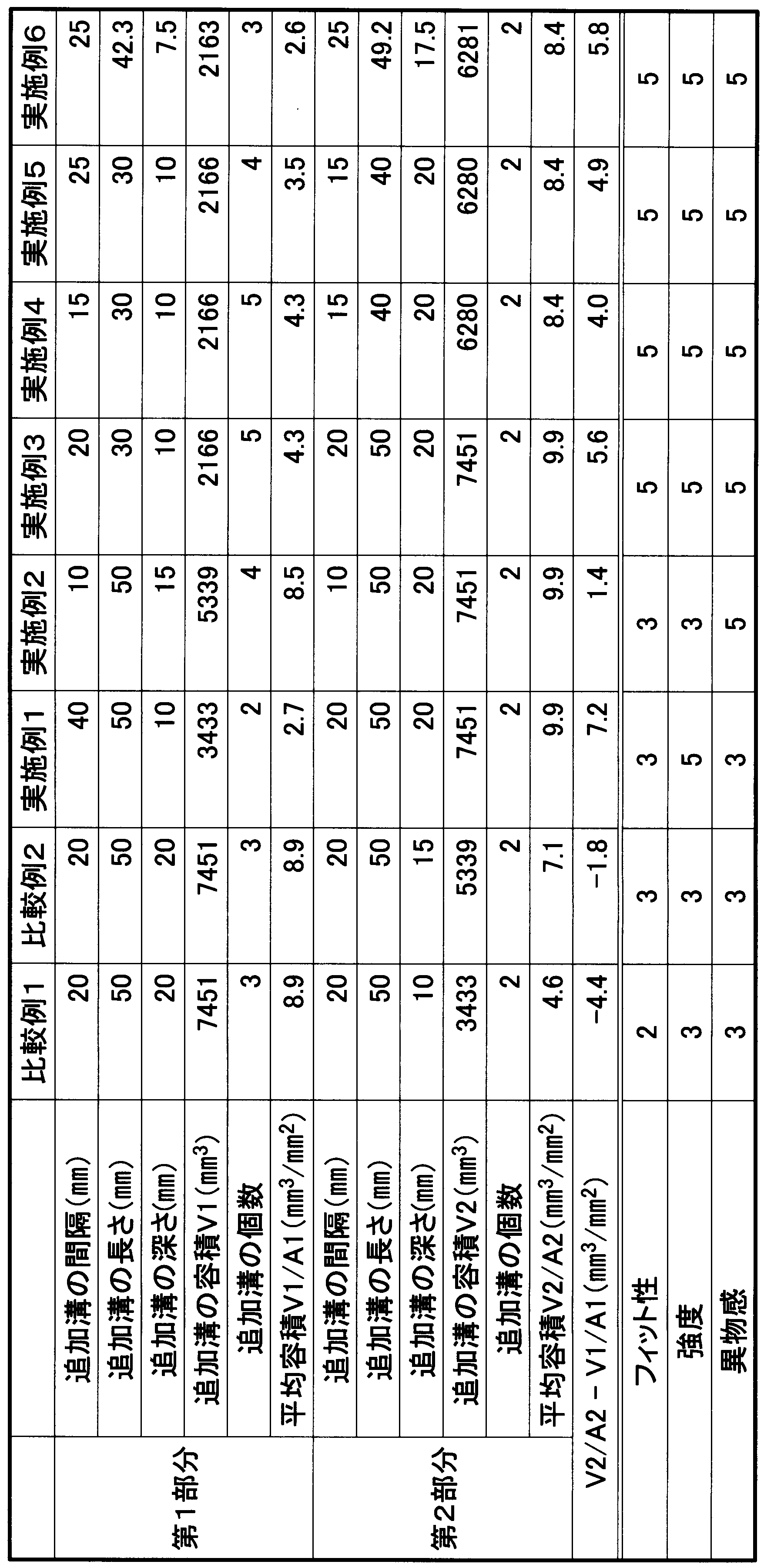
本検証試験では、各シート用パッドにおいて、フィット性、強度、異物感それぞれについて確認した。
結果は上記表1に併記した。実施例1~6のシート用パッドでは、比較例1、2のシート用パッドに対して、フィット性を確保した上で、異物感の低減および強度の向上の少なくとも一方を実現できていることが確認された。実施例3~6のシート用パッドでは、比較例1、2のシート用パッドに対して、フィット性および強度を向上させた上で、異物感を低減させていることが確認された。実施例3~6では、前記減じた値が2.0~6.0(mm3/mm2)となっている。
11 乗員当接面
11a 主受圧領域
11b 副受圧領域
15 区画溝
16 追加溝
17 第1部分
18 第2部分
H 乗員
H1 臀部
H2 腰部
Claims (6)
- 発泡成形体により形成されたシート用パッドであって、
シート用パッドの平面視において、長手方向に長く短手方向に短い矩形状に形成された乗員当接面が設けられ、
前記乗員当接面は、乗員の臀部または腰部が当接する主受圧領域と、前記主受圧領域に前記長手方向に隣接する副受圧領域と、を備え、
前記乗員当接面には、前記長手方向に延びて前記主受圧領域および前記副受圧領域にわたって配置された区画溝が設けられ、
前記区画溝は、前記短手方向に並列して複数配置され、
前記区画溝の底面には、追加溝が形成され、
前記区画溝のうち、前記主受圧領域に位置する第1部分では、前記副受圧領域に位置する第2部分よりも、前記区画溝の底面の単位面積あたりの前記追加溝の容積の割合である平均容積が小さいシート用パッド。 - 前記追加溝の溝幅は、前記区画溝の溝幅と同等である請求項1記載のシート用パッド。
- 前記第2部分では、前記第1部分よりも前記平均容積が2.0~6.0(mm3/mm2)大きい請求項1または2に記載のシート用パッド。
- 前記追加溝は、前記長手方向に間隔をあけて複数設けられ、
複数の前記追加溝では、前記長手方向に沿う前記主受圧領域側に位置する前記追加溝から前記副受圧領域側に位置する前記追加溝に向けて、容積が大きくなっている請求項1から3のいずれか1項に記載のシート用パッド。 - 前記追加溝の前記長手方向の大きさは、前記長手方向に隣り合う前記追加溝同士の間隔よりも大きい請求項4記載のシート用パッド。
- 前記追加溝の底面は、凹曲面状に形成されている請求項1から5のいずれか1項に記載のシート用パッド。
Priority Applications (4)
| Application Number | Priority Date | Filing Date | Title |
|---|---|---|---|
| US15/524,726 US10173566B2 (en) | 2015-01-19 | 2016-01-13 | Seat pad |
| EP16740030.8A EP3248512B1 (en) | 2015-01-19 | 2016-01-13 | Seat pad |
| CN201680003752.0A CN106998922B (zh) | 2015-01-19 | 2016-01-13 | 座椅用垫 |
| JP2016570586A JP6588474B2 (ja) | 2015-01-19 | 2016-01-13 | シート用パッド |
Applications Claiming Priority (2)
| Application Number | Priority Date | Filing Date | Title |
|---|---|---|---|
| JP2015007648 | 2015-01-19 | ||
| JP2015-007648 | 2015-01-19 |
Publications (1)
| Publication Number | Publication Date |
|---|---|
| WO2016117423A1 true WO2016117423A1 (ja) | 2016-07-28 |
Family
ID=56416970
Family Applications (1)
| Application Number | Title | Priority Date | Filing Date |
|---|---|---|---|
| PCT/JP2016/050782 Ceased WO2016117423A1 (ja) | 2015-01-19 | 2016-01-13 | シート用パッド |
Country Status (5)
| Country | Link |
|---|---|
| US (1) | US10173566B2 (ja) |
| EP (1) | EP3248512B1 (ja) |
| JP (1) | JP6588474B2 (ja) |
| CN (1) | CN106998922B (ja) |
| WO (1) | WO2016117423A1 (ja) |
Families Citing this family (3)
| Publication number | Priority date | Publication date | Assignee | Title |
|---|---|---|---|---|
| EP3626131A4 (en) * | 2017-05-16 | 2020-04-22 | Bridgestone Corporation | MOLDED FOAM BODY |
| JP7039275B2 (ja) * | 2017-12-14 | 2022-03-22 | 株式会社ブリヂストン | 車両用シート、及び、パッド振動特性の調整方法 |
| CN116729222A (zh) * | 2022-03-01 | 2023-09-12 | 李尔公司 | 凹形表面处用于两种样式的通用泡沫设计 |
Citations (4)
| Publication number | Priority date | Publication date | Assignee | Title |
|---|---|---|---|---|
| JPS528488Y1 (ja) * | 1969-10-28 | 1977-02-23 | ||
| JPS56132910A (en) * | 1980-03-22 | 1981-10-17 | Tachikawa Spring Co | Seat pad of seat |
| JP2005021263A (ja) * | 2003-06-30 | 2005-01-27 | Geltec Co Ltd | 体圧分散型クッション材 |
| JP2008132254A (ja) * | 2006-11-29 | 2008-06-12 | Inoac Corp | クッションパッド及びその発泡成形型 |
Family Cites Families (23)
| Publication number | Priority date | Publication date | Assignee | Title |
|---|---|---|---|---|
| US3401217A (en) * | 1963-07-02 | 1968-09-10 | Goodyear Tire & Rubber | Method of molding a foam cushion having seam grooves |
| US3713696A (en) * | 1971-05-20 | 1973-01-30 | Gen Motors Corp | Vehicle seat construction |
| US3848926A (en) * | 1972-03-03 | 1974-11-19 | Nhk Spring Co Ltd | Occupant seat |
| CH601899A5 (ja) * | 1975-07-08 | 1978-07-14 | Bbc Brown Boveri & Cie | |
| US4191424A (en) * | 1978-07-17 | 1980-03-04 | Flex-O-Lators, Inc. | Support grid for upholstered seating |
| AU592592B2 (en) * | 1986-09-15 | 1990-01-18 | Tachi-S Co., Ltd. | Vehicle seat |
| JPH0615551U (ja) | 1992-08-07 | 1994-03-01 | トヨタ車体株式会社 | 車両用シートのシートバック構造 |
| FR2707972B1 (fr) * | 1993-06-29 | 1995-09-22 | Bfa | Perfectionnements aux matelassures de sièges de véhicules automobiles. |
| US6089657A (en) * | 1997-09-11 | 2000-07-18 | Toyo Tire & Rubber Co., Ltd. | Seat cushion pad for automobiles |
| EP1086852B1 (de) * | 1999-09-21 | 2004-01-28 | Johnson Controls GmbH | Sitzpolster für Fahrzeugsitze |
| US6543844B1 (en) * | 2000-02-15 | 2003-04-08 | Bloorview Macmillan Centre | Seating furniture for children |
| US6893087B2 (en) * | 2002-11-18 | 2005-05-17 | Stearns Inc. | All terrain vehicle seat cushion |
| WO2006102751A1 (en) * | 2005-03-30 | 2006-10-05 | Woodbridge Foam Corporation | Foam seat element, mold for the production thereof and method to manufacture the mold |
| EP1915927B1 (en) * | 2005-08-18 | 2011-03-30 | Bridgestone Corporation | Vehicle seat pad |
| US8162402B2 (en) * | 2008-10-27 | 2012-04-24 | Toyota Boshoku Kabushikia Kaisha | Vehicular seats |
| KR101114174B1 (ko) * | 2009-05-13 | 2012-02-22 | 기아자동차주식회사 | 배수장치를 구비한 자동차용 시트쿠션 |
| EP3354514B1 (en) * | 2010-12-24 | 2019-11-27 | TS Tech Co., Ltd. | Vehicle seat |
| JP5872434B2 (ja) * | 2012-10-04 | 2016-03-01 | 日本発條株式会社 | 車両用シート |
| JP5976511B2 (ja) | 2012-11-26 | 2016-08-23 | 東洋ゴム工業株式会社 | シートパッド |
| JP6675822B2 (ja) * | 2014-07-24 | 2020-04-08 | 株式会社東洋クオリティワン | クッションパッドの製造方法 |
| JP6308905B2 (ja) * | 2014-08-05 | 2018-04-11 | 東洋ゴム工業株式会社 | クッションパッド |
| JP2016041211A (ja) * | 2014-08-19 | 2016-03-31 | 東洋ゴム工業株式会社 | クッションパッド |
| JP6102901B2 (ja) * | 2014-12-19 | 2017-03-29 | トヨタ自動車株式会社 | 車両用シート |
-
2016
- 2016-01-13 WO PCT/JP2016/050782 patent/WO2016117423A1/ja not_active Ceased
- 2016-01-13 EP EP16740030.8A patent/EP3248512B1/en active Active
- 2016-01-13 JP JP2016570586A patent/JP6588474B2/ja active Active
- 2016-01-13 US US15/524,726 patent/US10173566B2/en not_active Expired - Fee Related
- 2016-01-13 CN CN201680003752.0A patent/CN106998922B/zh active Active
Patent Citations (4)
| Publication number | Priority date | Publication date | Assignee | Title |
|---|---|---|---|---|
| JPS528488Y1 (ja) * | 1969-10-28 | 1977-02-23 | ||
| JPS56132910A (en) * | 1980-03-22 | 1981-10-17 | Tachikawa Spring Co | Seat pad of seat |
| JP2005021263A (ja) * | 2003-06-30 | 2005-01-27 | Geltec Co Ltd | 体圧分散型クッション材 |
| JP2008132254A (ja) * | 2006-11-29 | 2008-06-12 | Inoac Corp | クッションパッド及びその発泡成形型 |
Non-Patent Citations (1)
| Title |
|---|
| See also references of EP3248512A4 * |
Also Published As
| Publication number | Publication date |
|---|---|
| EP3248512B1 (en) | 2019-05-22 |
| JPWO2016117423A1 (ja) | 2017-10-26 |
| CN106998922A (zh) | 2017-08-01 |
| CN106998922B (zh) | 2020-03-24 |
| US10173566B2 (en) | 2019-01-08 |
| JP6588474B2 (ja) | 2019-10-09 |
| EP3248512A1 (en) | 2017-11-29 |
| US20170327020A1 (en) | 2017-11-16 |
| EP3248512A4 (en) | 2018-02-21 |
Similar Documents
| Publication | Publication Date | Title |
|---|---|---|
| US8360530B2 (en) | Vehicle seat | |
| US9004605B2 (en) | Vehicle seat | |
| CN104340099B (zh) | 座椅缓冲垫 | |
| JP6588474B2 (ja) | シート用パッド | |
| JP2009078142A (ja) | 車両用シートパッド及びその製造方法 | |
| US10532678B2 (en) | Seat pad and seat pad production device | |
| JP5242088B2 (ja) | 自動車用座席のクッション | |
| CN107031476B (zh) | 缓冲垫 | |
| JP2014205490A (ja) | シートクッションパッド | |
| JP7785557B2 (ja) | シートパッド | |
| CN107614319B (zh) | 座垫 | |
| CN107614321B (zh) | 座垫 | |
| JP4447264B2 (ja) | 座席シート | |
| JP5326428B2 (ja) | 車両用シート | |
| CN107614320B (zh) | 座垫 | |
| JP2010184085A (ja) | 車両用シートパッド | |
| JP7239311B2 (ja) | 車両用シートパッド | |
| JP2010284249A (ja) | シートクッションパッド | |
| JP5569610B2 (ja) | 乗物用シート | |
| JP5891951B2 (ja) | 車両用シート | |
| JP2005000452A (ja) | シートクッションパッド | |
| JP2026023633A (ja) | シートクッションおよびシート | |
| CN117962717A (zh) | 车辆座椅组件以及车辆 | |
| JP2014223111A (ja) | 乗物用シート |
Legal Events
| Date | Code | Title | Description |
|---|---|---|---|
| 121 | Ep: the epo has been informed by wipo that ep was designated in this application |
Ref document number: 16740030 Country of ref document: EP Kind code of ref document: A1 |
|
| ENP | Entry into the national phase |
Ref document number: 2016570586 Country of ref document: JP Kind code of ref document: A |
|
| WWE | Wipo information: entry into national phase |
Ref document number: 15524726 Country of ref document: US |
|
| REEP | Request for entry into the european phase |
Ref document number: 2016740030 Country of ref document: EP |
|
| NENP | Non-entry into the national phase |
Ref country code: DE |