WO2016117445A1 - 電力変換装置 - Google Patents
電力変換装置 Download PDFInfo
- Publication number
- WO2016117445A1 WO2016117445A1 PCT/JP2016/050976 JP2016050976W WO2016117445A1 WO 2016117445 A1 WO2016117445 A1 WO 2016117445A1 JP 2016050976 W JP2016050976 W JP 2016050976W WO 2016117445 A1 WO2016117445 A1 WO 2016117445A1
- Authority
- WO
- WIPO (PCT)
- Prior art keywords
- phase
- winding
- unit
- transformer
- positive
- Prior art date
- Legal status (The legal status is an assumption and is not a legal conclusion. Google has not performed a legal analysis and makes no representation as to the accuracy of the status listed.)
- Ceased
Links
Images




Classifications
-
- H—ELECTRICITY
- H02—GENERATION; CONVERSION OR DISTRIBUTION OF ELECTRIC POWER
- H02M—APPARATUS FOR CONVERSION BETWEEN AC AND AC, BETWEEN AC AND DC, OR BETWEEN DC AND DC, AND FOR USE WITH MAINS OR SIMILAR POWER SUPPLY SYSTEMS; CONVERSION OF DC OR AC INPUT POWER INTO SURGE OUTPUT POWER; CONTROL OR REGULATION THEREOF
- H02M7/00—Conversion of AC power input into DC power output; Conversion of DC power input into AC power output
- H02M7/42—Conversion of DC power input into AC power output without possibility of reversal
- H02M7/44—Conversion of DC power input into AC power output without possibility of reversal by static converters
- H02M7/48—Conversion of DC power input into AC power output without possibility of reversal by static converters using discharge tubes with control electrode or semiconductor devices with control electrode
- H02M7/483—Converters with outputs that each can have more than two voltages levels
-
- H—ELECTRICITY
- H02—GENERATION; CONVERSION OR DISTRIBUTION OF ELECTRIC POWER
- H02M—APPARATUS FOR CONVERSION BETWEEN AC AND AC, BETWEEN AC AND DC, OR BETWEEN DC AND DC, AND FOR USE WITH MAINS OR SIMILAR POWER SUPPLY SYSTEMS; CONVERSION OF DC OR AC INPUT POWER INTO SURGE OUTPUT POWER; CONTROL OR REGULATION THEREOF
- H02M1/00—Details of apparatus for conversion
- H02M1/12—Arrangements for reducing harmonics from AC input or output
-
- H—ELECTRICITY
- H02—GENERATION; CONVERSION OR DISTRIBUTION OF ELECTRIC POWER
- H02M—APPARATUS FOR CONVERSION BETWEEN AC AND AC, BETWEEN AC AND DC, OR BETWEEN DC AND DC, AND FOR USE WITH MAINS OR SIMILAR POWER SUPPLY SYSTEMS; CONVERSION OF DC OR AC INPUT POWER INTO SURGE OUTPUT POWER; CONTROL OR REGULATION THEREOF
- H02M7/00—Conversion of AC power input into DC power output; Conversion of DC power input into AC power output
- H02M7/42—Conversion of DC power input into AC power output without possibility of reversal
- H02M7/44—Conversion of DC power input into AC power output without possibility of reversal by static converters
- H02M7/48—Conversion of DC power input into AC power output without possibility of reversal by static converters using discharge tubes with control electrode or semiconductor devices with control electrode
-
- H—ELECTRICITY
- H02—GENERATION; CONVERSION OR DISTRIBUTION OF ELECTRIC POWER
- H02M—APPARATUS FOR CONVERSION BETWEEN AC AND AC, BETWEEN AC AND DC, OR BETWEEN DC AND DC, AND FOR USE WITH MAINS OR SIMILAR POWER SUPPLY SYSTEMS; CONVERSION OF DC OR AC INPUT POWER INTO SURGE OUTPUT POWER; CONTROL OR REGULATION THEREOF
- H02M7/00—Conversion of AC power input into DC power output; Conversion of DC power input into AC power output
- H02M7/42—Conversion of DC power input into AC power output without possibility of reversal
- H02M7/44—Conversion of DC power input into AC power output without possibility of reversal by static converters
- H02M7/48—Conversion of DC power input into AC power output without possibility of reversal by static converters using discharge tubes with control electrode or semiconductor devices with control electrode
- H02M7/483—Converters with outputs that each can have more than two voltages levels
- H02M7/4835—Converters with outputs that each can have more than two voltages levels comprising two or more cells, each including a switchable capacitor, the capacitors having a nominal charge voltage which corresponds to a given fraction of the input voltage, and the capacitors being selectively connected in series to determine the instantaneous output voltage
Definitions
- Embodiment of this invention is related with the power converter device which converts electric power mutually between alternating current and direct current
- a three-phase two-level converter is applied to a converter that converts alternating current in a power system into direct current, and a three-phase two-level inverter is used as an inverter that converts direct current into alternating current and is used for driving a motor. Has been applied.
- These three-phase two-level power conversion devices can be configured with a minimum of six semiconductor switching elements required to mutually convert power between three-phase alternating current and direct current. . Therefore, the three-phase, two-level power conversion device can be reduced in size and cost. For this reason, great expectations are placed on the three-phase, two-level power conversion device, and further improvement in performance is required.
- PWM control is generally used to control the magnitude of the output voltage by controlling the pulse width.
- PWM pulse (Width modulation).
- a filter that absorbs harmonics is inserted into a three-phase AC output. This is because power system connection devices such as DC power transmission are required to reduce harmonic components contained in distorted waves generated by switching.
- the PWM switching frequency cannot be increased, and therefore a harmonic absorption filter is indispensable.
- Such a filter is usually composed of a reactor, a capacitor, or the like that suppresses harmonic components, but is responsible for reducing the harmonic components that flow out to the power system to a level that does not adversely affect other devices. For this reason, reactors and capacitors for suppressing harmonics have a large capacity, are expensive, and are often heavy. Therefore, by inserting a filter that absorbs harmonics, problems such as an increase in cost and an increase in weight of the power conversion device have been incurred.
- Non-Patent Document 2 a circuit method described in Non-Patent Document 2 has been announced as a technique that eliminates the need for the filter.
- the power conversion device can be directly connected to the power system and the distribution system voltage without voltage step-down in a transformer generally used conventionally.
- symbols Up, Vp, and Wp are positive unit arms
- Un, Vn, and Wn are negative unit arms.
- the unit arm is a unit unit that includes a chopper bridge unit converter or the like.
- the configuration of the transformer can be easily simplified. Since the transformer has a large weight and volume, and the cost of the entire system is relatively large, an inexpensive and small-sized power conversion device can be obtained by simplifying the transformer.
- the power converter shown in FIG. 9 includes a DC capacitor connected in parallel to the switching element as a voltage source for switching the presence or absence of voltage output in accordance with switching. Since this DC capacitor is for controlling the voltage value to be always constant, in principle, it is necessary to constantly flow a reflux current that circulates the DC power supply, and a short circuit path for charging and discharging is provided in each phase. .
- the three phases are connected to the same DC power supply, so if the DC voltage composite value of each phase is slightly different, an excessive short-circuit current flows between the phases, causing the equipment to May have adverse effects. Even if the average value of the DC voltage composite values of the respective phases coincides, if the ON / OFF timing and cycle are different, an excessively short-circuit current flows again.
- a power converter as shown in FIG. 8 has been proposed as a method of eliminating a reactor for dealing with an excessive short circuit current.
- the secondary winding and the tertiary winding are transformers formed of star windings, and the neutral points of the secondary winding and the tertiary winding are connected.
- production of an excessive short circuit current can be suppressed, without inserting a buffer reactor. Therefore, it is possible to output a low-harmonic voltage / current waveform without a harmonic absorption filter while eliminating a large and expensive reactor, and the cost and size of the apparatus can be reduced.
- harmonic currents such as a third harmonic current may be output unintentionally.
- the harmonic current becomes an exciting current of a transformer incorporated in the power converter, and becomes a factor that distorts the system voltage, which is a sine wave voltage. Therefore, in power converters, in addition to eliminating filters and large reactors that absorb harmonics, it is strongly desired to suppress the output of harmonic currents.
- Embodiments of the present invention have been proposed in order to solve the above-described problems, and harmonics that are output unintentionally by providing a transformer in which the secondary winding and the tertiary winding are each delta-connected.
- An object of the present invention is to provide a power conversion device that can suppress the generation of current and exhibit high reliability without fear of inducing voltage distortion of the power system.
- the power conversion device of the present embodiment is characterized by having the following configuration. (1) Provided with a three-phase three-winding transformer in which the secondary winding and the tertiary winding are each delta-connected. (2) The neutral points of the phase windings of the same phase of the secondary winding and the tertiary winding of the three-phase three-winding transformer are connected to each other. (3) Further, a leg having two switching elements having a self-extinguishing capability connected in series and a capacitor are connected in parallel to form a unit unit, and the positive and negative unit arms in which the unit units are connected in series. Is provided.
- One end of the positive unit arm is connected to the positive side of the DC power supply, and the other end is connected to each phase output terminal of the secondary winding of the three-phase three-winding transformer.
- One end of the negative-side unit arm is connected to the negative side of the DC power supply, and the other end is connected to each phase output terminal of the tertiary winding of the three-phase three-winding transformer.
- the circuit block diagram of 1st Embodiment The circuit block diagram which shows the unit unit of 1st Embodiment.
- (A) is a voltage waveform diagram of the positive unit unit
- B) is a voltage waveform diagram of the negative unit unit
- C) is a voltage waveform diagram of the secondary winding of the transformer
- (D) is a transformer tertiary winding.
- Voltage waveform diagram of the line (E) is the output voltage waveform diagram of the transformer.
- the circuit block diagram which shows the coil
- FIGS. 1 to 5 are circuit configuration diagrams of the first embodiment
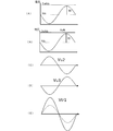
- FIG. 6 is a voltage waveform diagram of the first embodiment.
- the first embodiment is a power converter that is connected between a three-phase AC system and a DC system, and converts a three-phase 50 Hz power source into DC power via a three-phase three-winding transformer A that is an insulating transformer. Device.
- the first embodiment includes a three-phase three-winding transformer A, a DC power source B, and positive unit arms Up, Vp, Wp, and two unit units C connected in series. Negative unit arms Un, Vn, and Wn are provided.
- the number of unit units C is two, but any number of unit units C may be used as long as it is one or more.
- the unit arm will be described.
- six unit arms are provided.
- Three positive unit arms Up, Vp, and Wp and three negative unit arms Un, Vn, and Wn are provided.
- the positive unit arms Up, Vp, and Wp one end is connected to the positive side of the DC power source B, and the other end is connected to each phase output end of the secondary winding of the three-phase three-winding transformer A.
- the negative side unit arms Un, Vn, Wn one end is connected to the negative side of the DC power source B, and the other end is connected to each phase output end of the tertiary winding of the three-phase three-winding transformer A.
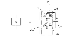
- the unit unit C constituting the unit arms Up, Vp, Wp, Un, Vn, Wn will be described with reference to the circuit diagram of FIG.
- the unit unit C includes a chopper bridge unit converter, and a leg 20 (shown by a dotted line) and a capacitor 30 are connected in parallel as shown in FIG.
- Switching elements 21U and 21X having a self-extinguishing ability are connected to the leg 20 in series.
- IGB ⁇ having a rating of about 6500V is used, and freewheeling diodes 22U and 22X are connected in antiparallel.
- the three-phase three-winding transformer A has a primary winding that is star-connected and is connected to three phases of the 50 Hz power source, that is, the R phase, S phase, and T phase.
- the secondary winding and the tertiary winding are each delta-connected.
- the three-phase three-winding transformer A has a configuration in which the transformer iron core is divided for each phase of the primary winding, and the iron core of the secondary winding and the iron core of the tertiary winding are separated. Further, the winding ratio between the primary winding and the secondary winding is 1: 1.
- the three-phase three-winding transformer A is provided separately for each phase on the positive side and the negative side. The side with the black dot shown in each winding is the positive side.
- the same phase is mutually connected at the neutral point of each phase winding of the secondary winding and the tertiary winding. That is, the R-phase neutral point NP_R2 of the secondary winding and the R-phase neutral point NP_R3 of the tertiary winding are connected, and the S-phase neutral point NP_S2 of the secondary winding and the S-phase neutral point of the tertiary winding NP_S3 is connected, and the T-phase neutral point NP_T2 of the secondary winding and the T-phase neutral point NP_T3 of the tertiary winding are connected.
- each unit arm is connected to two windings of the three-phase three-winding transformer A. That is, the positive unit arms Up, Vp, and Wp are connected to the secondary winding side, and more specifically, the unit arm Up is connected to the winding Rp1 and the winding Tp2.
- the unit arm Vp is connected to the winding Sp1 and the winding Rp2, and the unit arm Wp is connected to the winding Tp1 and the winding Sp2.
- the negative unit arms Un, Vn, and Wn are connected to the tertiary winding side.
- the unit arm Un is connected to the winding Rn1 and the winding Tn2
- the unit arm Vn is connected to the winding Sn1 and the winding Rn2
- the unit arm Wn is connected to the winding Tn1 and the winding Sn2.
- FIG. 4 shows the connection relationship between such a three-phase three-winding transformer A, unit arms Up, Vp, Wp, Un, Vn, Wn and a DC power source B.
- One end of each unit arm Up, Vp, Wp of each positive phase is connected to the positive side of DC power supply B.
- one end of each unit arm Wp, Un, Vn of each phase on the negative side is connected to the negative side of the DC power source B.
- Harmonic absorption filters can be composed of reactors and capacitors that suppress harmonic components, but the harmonic components that flow into the power system must be reduced to a level that does not affect other equipment. For this reason, a filter having a large capacity is required, which causes problems such as an increase in size.
- a multi-level power conversion device in which unit units C are connected in multiple stages in series is configured.
- the output waveform of the first embodiment can be made closer to a sine wave. Therefore, harmonics can be reliably suppressed to a level that does not affect other components without providing a filter that absorbs harmonics.
- the secondary winding and the tertiary winding each have a delta connection configuration.
- the neutral point of each phase winding of the same phase of a secondary winding and a tertiary winding is mutually connected by the secondary winding and the tertiary winding.
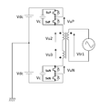
- the unit arm is composed of two unit units C. Let the neutral point of the DC power supply B be the ground point and use the voltage as a reference, and let the voltage at the AC output point seen from the ground point be Vu.
- Vu is a three-phase AC voltage Vu, Vv, Vw when a 50 Hz AC power supply R, S, T phase voltage is delta star converted, and this delta star conversion is an existing technology in general AC theory. The description is omitted here.
- the positive and negative voltages of the DC power supply B are Vdc
- the capacitor voltage of the unit unit C is Vc
- the output voltage of the unit unit C connected to the positive power supply side is VuP
- the unit unit C connected to the negative power supply side The output voltage is VuN.
- an AC voltage command to be output that is calculated by the host system is VuRef.
- Negative side unit VuN Vdc ⁇ VuRef
- VuN Vdc ⁇ VuRef
- the voltage waveform of this VuN is shown in FIG.
- the waveform of the voltage Vu3 of the tertiary winding in the three-phase three-winding transformer A is shown in FIG.
- the average value of PowerP in one AC cycle is negative. That is, if the output voltage control is performed only in the above operation mode, the capacitor voltage average value of the positive unit unit C cannot be kept constant, and the operation cannot be continued. Similarly, for the capacitor voltage of the negative unit C, PowerN when operating at a power factor of 1 has a positive average value in one AC cycle, and the capacitor voltage average value of the negative unit C is negative. Cannot be kept constant, and driving cannot be continued.
- the negative side of the DC power source B is passed from the positive side of the DC power source B through the positive unit unit C, the three-phase three-winding transformer A, and the negative unit unit C.
- a charging / discharging current is passed in a direct current along the path to the side.
- the constant control correction value ⁇ VfcControl of the DC capacitor voltage average value is calculated by the following formula, and the output voltage commands VuP and VuN of the positive unit unit C are corrected and output.
- VCref is the unit unit capacitor voltage command value, which is a preset value.
- VCu_AVE is the capacitor voltage average value of all U-phase positive and negative unit units.
- G (s) is the control gain and s is the Laplace operator. Proportional integral control is suitable. Such an operation is the same as that of the prior art, but in the prior art, it is necessary to specially install a large reactor such as a buffer reactor for preventing a sudden increase in the DC circulating current.
- the three-phase three-winding transformer A which is an insulating transformer, is included in the DC circulating current path.
- the leakage inductance component can function as a reactor. Thereby, it is possible to suppress a sudden increase in the DC circulating current, and a large-sized reactor such as a buffer reactor is not required at a high cost.
- a low-harmonic voltage-current waveform can be output without a harmonic absorption filter. Further, it is possible to control the average value of the capacitor voltage of the unit unit C to be constant without suppressing a rapid increase of the DC circulating current without installing a large-sized reactor such as a buffer reactor at high cost. Therefore, it is possible to omit a harmonic absorption filter and a high-cost large-sized reactor, and it is possible to provide an inexpensive and small-sized power conversion device.
- the secondary winding and the tertiary winding of the three-phase three-winding transformer A have a delta connection configuration, and each phase winding of the same phase of the secondary winding and the tertiary winding.
- the neutral points of the line are connected to each other. Therefore, it is possible to suppress the generation of harmonic currents that are output unintentionally.
- the harmonic current does not become the exciting current of the three-phase three-winding transformer A, and the system voltage can maintain a sine wave voltage, and there is no concern that the voltage becomes distorted.
- the three-phase three-winding transformer A ′ is configured to divide the transformer core for each phase of the primary winding and wind the secondary winding and the tertiary winding around the same iron core. It is good.
- the DC component is canceled and the DC magnetic flux generated by the DC charge / discharge current of the capacitor is mutually exchanged. It becomes possible to cancel each other. For this reason, iron core magnetic saturation can be prevented, the saturation magnetic flux density can be reduced, and the transformer core can be further reduced in size.
- Each leg of the three-phase three-leg transformer A may have a primary primary winding, a secondary primary winding, and a tertiary primary winding. Thereby, each phase direct current magnetic flux can cancel each other like the above-mentioned embodiment. Furthermore, it is possible to achieve the same miniaturization as a normal three-phase transformer by using a three-phase three-leg iron core.
- direct current to alternating current can be converted with the same configuration, and conversely, alternating current to direct current can be converted. That is, the power converter of this embodiment can be configured as an inverter or a converter.
Landscapes
- Engineering & Computer Science (AREA)
- Power Engineering (AREA)
- Inverter Devices (AREA)
- Rectifiers (AREA)
Abstract
意図せず出力される高調波電流が電力系統の歪を誘発させる懸念のない、安価で小型であり、かつ高い信頼性を発揮する電力変換装置を提供する。3相3巻線トランスAは、二次巻線と三次巻線のそれぞれ同一相同士の各相巻線の中性点を二次巻線と三次巻線とで互いに接続する。自己消弧能力を持つスイッチング素子を直列に2個接続したレグとコンデンサとを並列に接続して単位ユニットCとして、これを2つ直列に接続した正側の単位アームUp、Vp、Wpおよび負側の単位アームUn、Vn、Wnを備える。正側の単位アームは、一端を直流電源Bの正側に接続し、他の一端を3相3巻線トランスAの二次巻線の各相出力端に接続する。負側の単位アームは、一端を直流電源Bの負側に接続し、他の一端を3相3巻線トランスAの三次巻線の各相出力端に接続する。
Description
本発明の実施形態は、交流と直流との間で相互に電力を変換する電力変換装置に関するものである。
近年、海底ケーブル等、大規模な直流送電の必要性が増大しており、電力変換装置のニーズが高まっている。このような電力変換装置としては、電力系統の交流を直流に変換するコンバータには3相2レベルコンバータが適用され、直流を交流に変換してモータ駆動に用いるインバータには3相2レベルインバータが適用されている。
これら3相2レベルの電力変換装置は、3相交流と直流との間で相互に電力を変換する上で必要となる半導体スイッチング素子を、最小限となる6個で構成することが可能である。したがって、3相2レベルの電力変換装置では小型化および低コスト化を図ることができる。このため、3相2レベルの電力変換装置には大きな期待が寄せられており、さらなる性能の向上が求められている。
3相2レベルの電力変換装置の制御方法としては、パルス幅の制御により出力電圧の大きさを制御するPWM制御が一般的である。具体的には3相2レベルインバータの場合、入力される直流電圧をVdcとしたとき、相ごとに、所定のタイミングで+Vdc/2と、-Vdc/2の2値の切替えを、PWM(パルス幅変調)で行う。これにより、3相2レベルインバータからの出力波形を、擬似的に生成された交流の波形とすることができる。
一般に、従来の電力変換装置では、3相交流出力に高調波を吸収するフィルタが挿入されている。これは、直流送電などの電力系統接続機器においては、スイッチングによって発生するひずみ波に含まれる高調波成分を低減することが要請されているからである。特に、高耐圧のスイッチング周波数を使用する高電圧モータドライブ等では、PWMスイッチング周波数を高くできないので、高調波吸収用のフィルタが不可欠となっている。
このようなフィルタは通常、高調波成分を抑制するリアクトルやコンデンサ等で構成されるが、電力系統に流れ出す高調波成分を、他の機器に悪影響を及ぼさないレベルにまで低減させる責務がある。そのため、高調波抑制用のリアクトルやコンデンサは容量が大きく、高価であり、重量も重いものが多かった。したがって、高調波を吸収するフィルタを挿入することにより、電力変換装置のコスト向上や重量増加といった不具合を招いていた。
そこで、上記のフィルタを不要とする技術として、非特許文献2に記載の回路方式等が発表されている。例えば図9に示した回路構成では、従来一般的に用いられているトランスでの電圧降圧なしに、電力系統および配電系統電圧に対し電力変換装置を直接接続することができる。なお、図9において、符号Up、Vp、Wpは正側の単位アーム、Un、Vn、Wnは負側の単位アームであり、単位アームとはチョッパブリッジ単位変換器等からなる単位ユニットを構成要素とする。
図9に示したトランスを有する電力変換装置によれば、出力電圧および電流波形が多レベル化により正弦波に近づくため、高調波を吸収するためのフィルタが不要になり、低コスト化および軽量化といったメリットを享受することができる。しかも、図9の回路構成を実現することで、トランスの構成を容易に簡略化することができる。トランスは重量および体積が大きく、またシステム全体に占めるコストも比較的大きいので、その簡略化を進めることにより、安価で小型の電力変換装置を得ることができる。
図9に示した電力変換装置では、スイッチングに応じて電圧出力の有無を切り替える電圧源として、スイッチング素子に並列に接続した直流コンデンサを備えている。この直流コンデンサは電圧値を常に一定に制御するためのものなので、原理的に直流電源を還流させる還流電流を常時流すことが必要であり、各相に充放電のための短絡経路を設けている。
しかし、3相用の電力変換装置では3相を同一の直流電源に接続しているので、各相の直流電圧合成値がわずかでも異なると、相間に過大な短絡電流が流れてしまい、機器に悪影響を与える可能性がある。また、仮に各相の直流電圧合成値の平均値が一致したとしても、オンオフのタイミングや周期が異なれば、やはり過大な短絡電流が流れることになる。
そこで、相間に流れる過大な短絡電流に対処するために、バッファリアクトルのような大型のリアクトルを各相に挿入して、短絡電流に制限を加えることが考えられる。しかしながら、バッファリアクトル等のリアクトルは大型であり、高価であった。
すなわち、図9に示した従来技術では、高調波を吸収するフィルタは不要になるものの、バッファリアクトル等、大型のリアクトルの挿入を余儀なくされる。このため、電力変換装置は大きくなり、且つコストも上昇した。その結果、前記フィルタを無くしたことによるメリットが、バッファリアクトル挿入によるデメリットによって相殺されてしまい、安価で小型の電力変換装置の実現が困難となっていた。
そこで、過大な短絡電流に対処するためのリアクトルを無くす方式として、図8に示すような電力変換装置が提案されている。図8の回路構成を持つ電力変換装置では、二次巻線および三次巻線をスター巻線で構成されるトランスとし、二次巻線および三次巻線の中性点を接続している。このようなトランスを備えた電力変換装置によれば、バッファリアクトルを挿入することなく、過大な短絡電流の発生を抑えることができる。したがって、大型で高価なリアクトルを無くしつつ、高調波吸収用のフィルタなしに低高調波の電圧電流波形を出力することが可能であり、装置の低コスト化および小型化を図ることができる。
2009年cigre論文予稿集Paper401(Multilevel Voltage-Sourced Converters for HVDC and FACTS Applications:Siemens AG)
ところで、電力変換装置では、3次高調波電流等の高調波電流が意図せずに出力されることがある。高調波電流は、電力変換装置に組み込まれたトランスの励磁電流となり、正弦波電圧である系統電圧をひずませる要因となる。したがって電力変換装置においては、高調波を吸収するフィルタや大型のリアクトルをなくすことに加えて、高調波電流の出力を抑えることが強く望まれている。
本発明の実施形態は、以上の課題を解決するために提案されたものであり、二次巻線および三次巻線がそれぞれデルタ結線されたトランスを備えることにより、意図せず出力される高調波電流の発生を抑えて、電力系統の電圧の歪みを誘発させる懸念のない、高い信頼性を発揮することができる電力変換装置を提供することを目的とする。
上記のような課題を解決するため、本実施形態の電力変換装置は、以下の構成を有することを特徴としている。
(1) 二次巻線および三次巻線がそれぞれデルタ結線された3相3巻線トランスを備える。
(2)前記3相3巻線トランスの二次巻線と三次巻線のそれぞれ同一相同士の各相巻線の中性点を互いに接続する。
(3)さらに、自己消弧能力を持つスイッチング素子を直列に2個接続したレグとコンデンサとを並列に接続して単位ユニットとし、前記単位ユニットを直列に接続した正側および負側の単位アームを備える。
(4)前記正側の単位アームは、一端を直流電源の正側に接続し、他の一端を前記3相3巻線トランスの二次巻線の各相出力端に接続する。
(5)前記負側の単位アームは、一端を直流電源の負側に接続し、他の一端を前記3相3巻線トランスの三次巻線の各相出力端に接続する。
(1) 二次巻線および三次巻線がそれぞれデルタ結線された3相3巻線トランスを備える。
(2)前記3相3巻線トランスの二次巻線と三次巻線のそれぞれ同一相同士の各相巻線の中性点を互いに接続する。
(3)さらに、自己消弧能力を持つスイッチング素子を直列に2個接続したレグとコンデンサとを並列に接続して単位ユニットとし、前記単位ユニットを直列に接続した正側および負側の単位アームを備える。
(4)前記正側の単位アームは、一端を直流電源の正側に接続し、他の一端を前記3相3巻線トランスの二次巻線の各相出力端に接続する。
(5)前記負側の単位アームは、一端を直流電源の負側に接続し、他の一端を前記3相3巻線トランスの三次巻線の各相出力端に接続する。
[1]第1の実施形態
[構成]
第1の実施形態の構成について図1~図6を参照して説明する。図1~図5は第1の実施形態の回路構成図、図6は第1の実施形態の電圧波形図である。第1の実施形態は、3相の交流系統と直流系統との間に接続され、絶縁トランスである3相3巻線トランスAを介して、3相50Hzの電源を直流に電力変換する電力変換装置である。
[構成]
第1の実施形態の構成について図1~図6を参照して説明する。図1~図5は第1の実施形態の回路構成図、図6は第1の実施形態の電圧波形図である。第1の実施形態は、3相の交流系統と直流系統との間に接続され、絶縁トランスである3相3巻線トランスAを介して、3相50Hzの電源を直流に電力変換する電力変換装置である。
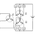
図1に示すように、第1の実施形態には、3相3巻線トランスAと、直流電源Bと、2つの単位ユニットCを直列に接続した正側の単位アームUp、Vp、Wpおよび負側の単位アームUn、Vn、Wnが設けられている。図1の例では、単位ユニットCを2個としたが、1個以上であれば、設置数はいくつでもよい。
(単位アーム)
まず、単位アームについて説明する。図1に示すように、第1の実施形態では6個の単位アームが設けられている。正側の単位アームUp、Vp、Wpと、負側の単位アームUn、Vn、Wnがそれぞれ3本ずつ設けられている。正側の単位アームUp、Vp、Wpについては、一端が直流電源Bの正側に接続され、他の一端が3相3巻線トランスAの二次巻線の各相出力端に接続される。負側の単位アームUn、Vn、Wnについては、一端が直流電源Bの負側に接続され、他の一端が3相3巻線トランスAの三次巻線の各相出力端に接続される。
まず、単位アームについて説明する。図1に示すように、第1の実施形態では6個の単位アームが設けられている。正側の単位アームUp、Vp、Wpと、負側の単位アームUn、Vn、Wnがそれぞれ3本ずつ設けられている。正側の単位アームUp、Vp、Wpについては、一端が直流電源Bの正側に接続され、他の一端が3相3巻線トランスAの二次巻線の各相出力端に接続される。負側の単位アームUn、Vn、Wnについては、一端が直流電源Bの負側に接続され、他の一端が3相3巻線トランスAの三次巻線の各相出力端に接続される。
(単位ユニット)
単位アームUp、Vp、Wp、Un、Vn、Wnを構成する単位ユニットCについて、図2の回路図を用いて説明する。単位ユニットCはチョッパブリッジ単位変換器からなり、図2に示すように、レグ20(点線にて示す)とコンデンサ30が並列に接続されている。レグ20には自己消弧能力を持つスイッチング素子21U、21Xが直列に接続されている。これらのスイッチング素子21U、21Xには、定格が6500V程度のIGBТが用いられており、逆並列に還流ダイオード22U、22Xが接続されている。
単位アームUp、Vp、Wp、Un、Vn、Wnを構成する単位ユニットCについて、図2の回路図を用いて説明する。単位ユニットCはチョッパブリッジ単位変換器からなり、図2に示すように、レグ20(点線にて示す)とコンデンサ30が並列に接続されている。レグ20には自己消弧能力を持つスイッチング素子21U、21Xが直列に接続されている。これらのスイッチング素子21U、21Xには、定格が6500V程度のIGBТが用いられており、逆並列に還流ダイオード22U、22Xが接続されている。
(3相3巻線トランス)
図1に示すように、3相3巻線トランスAは、一次巻線がスター結線され、50Hz電源の3相、つまりR相、S相、T相に接続される。また、3相3巻線トランスAは、二次巻線と三次巻線がそれぞれデルタ結線されている。
図1に示すように、3相3巻線トランスAは、一次巻線がスター結線され、50Hz電源の3相、つまりR相、S相、T相に接続される。また、3相3巻線トランスAは、二次巻線と三次巻線がそれぞれデルタ結線されている。
3相3巻線トランスAは、一次巻線の相ごとにトランス鉄心を分割し、二次巻線の鉄心と三次巻線の鉄心を別々にした構成となっている。また、一次巻線と二次巻線との間の巻線比は1:1である。3相3巻線トランスAは、各相で正側と負側に分けて設けられている。各巻線に示した黒点が付いている側が正側である。
3相3巻線トランスAにおいて、二次巻線と三次巻線のそれぞれの各相巻線の中性点は、同一相同士が互いに接続されている。すなわち、二次巻線のR相中性点NP_R2と三次巻線のR相中性点NP_R3とが接続され、二次巻線のS相中性点NP_S2と三次巻線のS相中性点NP_S3とが接続され、二次巻線のT相中性点NP_T2と三次巻線のT相中性点NP_T3とが接続されている。
(各部の接続関係)
図3では、3相3巻線トランスAのデルタ結線構造を分けて巻線構成を示している。二次巻線と三次巻線がそれぞれデルタ結線されているので、各単位アームは3相3巻線トランスAの2つの巻線と接続される。すなわち、正側の単位アームUp、Vp、Wpは二次巻線側に接続されており、より詳しくは、単位アームUpは巻線Rp1と巻線Tp2と接続され、
単位アームVpは巻線Sp1と巻線Rp2と接続され、単位アームWpは巻線Tp1と巻線Sp2と接続されている。
図3では、3相3巻線トランスAのデルタ結線構造を分けて巻線構成を示している。二次巻線と三次巻線がそれぞれデルタ結線されているので、各単位アームは3相3巻線トランスAの2つの巻線と接続される。すなわち、正側の単位アームUp、Vp、Wpは二次巻線側に接続されており、より詳しくは、単位アームUpは巻線Rp1と巻線Tp2と接続され、
単位アームVpは巻線Sp1と巻線Rp2と接続され、単位アームWpは巻線Tp1と巻線Sp2と接続されている。
また、負側の単位アームUn、Vn、Wnは三次巻線側に接続されており、より詳しくは、
単位アームUnは巻線Rn1と巻線Tn2と接続され、単位アームVnは巻線Sn1と巻線Rn2と接続され、単位アームWnは巻線Tn1と巻線Sn2と接続されている。
単位アームUnは巻線Rn1と巻線Tn2と接続され、単位アームVnは巻線Sn1と巻線Rn2と接続され、単位アームWnは巻線Tn1と巻線Sn2と接続されている。
図4では、このような3相3巻線トランスAと単位アームUp、Vp、Wp、Un、Vn、Wnと直流電源Bとの接続関係を示している。正側の各相の単位アームUp、Vp、Wpの一端は、それぞれ直流電源Bの正側に接続されている。また、負側の各相の単位アームWp、Un、Vnの一端は、それぞれ直流電源Bの負側に接続されている。
[作用]
(高調波の抑制)
半導体素子によるスイッチングにおいては、ひずみ波が発生し、このひずみ波に含まれる高調波成分が機器に影響を与えることが知られている。先に述べたように、この高調波成分に対処するため、発生した高調波を吸収するフィルタを挿入することが考えられていた。
(高調波の抑制)
半導体素子によるスイッチングにおいては、ひずみ波が発生し、このひずみ波に含まれる高調波成分が機器に影響を与えることが知られている。先に述べたように、この高調波成分に対処するため、発生した高調波を吸収するフィルタを挿入することが考えられていた。
高調波吸収用のフィルタは高調波成分を抑制するリアクトルやコンデンサから構成できるが、電力系統に流れ出す高調波成分を他の機器に影響を及ぼさないレベルまで低減させなくてはならない。そのため、大きな容量を持つフィルタが必要となり、大型化などの不具合を招いていた。
そこで第1の実施形態においては、単位ユニットCを直列に多段に接続したマルチレベルの電力変換装置を構成している。これにより、第1の実施形態の出力波形を、より正弦波に近づけることができる。したがって、高調波を吸収するフィルタを設けることなく、高調波成分を他の機器に影響を及ぼさないレベルにまで、高調波を確実に抑制することができる。
しかも、第1の実施形態では、3相3巻線トランスAにおいて、二次巻線、三次巻線がそれぞれデルタ結線構成となっている。そして、二次巻線と三次巻線のそれぞれ同一相同士の各相巻線の中性点を、二次巻線と三次巻線とで互いに接続している。このため、意図せず出力される高調波電流の発生を原理的に抑えることができる。したがって、高調波電流が3相3巻線トランスAの励磁電流となって系統電圧をひずませる心配がない。
(交流電圧出力動作)
本実施形態による交流波形の出力動作について、図5および図6を用いて説明する。図5においては、単位アームは2個の単位ユニットCで構成された場合である。直流電源Bの中性点を接地点として電圧基準として、接地点からみた交流出力点の電圧をVuとする。
本実施形態による交流波形の出力動作について、図5および図6を用いて説明する。図5においては、単位アームは2個の単位ユニットCで構成された場合である。直流電源Bの中性点を接地点として電圧基準として、接地点からみた交流出力点の電圧をVuとする。
Vuは、50Hz交流電源R,S,T相電圧をデルタスター変換したときの3相交流電圧Vu、Vv,Vwであり、このデルタスター変換は、一般的な交流理論で既存の技術であるからここでは説明を省略する。直流電源Bの正負それぞれの電圧をVdc、単位ユニットCのコンデンサ電圧をVcとし、正側電源側に接続される単位ユニットCの出力電圧をVuP、負側電源側に接続される単位ユニットCの出力電圧をVuNとする。また、上位のシステムで演算される出力したい交流電圧指令をVuRefとする。
(数1)
正側単位ユニットVuP=Vdc-VuRef
このVuPの電圧波形を、図6(A)に示す。また、3相3巻線トランスAにおける二次巻線の電圧Vu2の波形を、図6(C)に示す。
正側単位ユニットVuP=Vdc-VuRef
このVuPの電圧波形を、図6(A)に示す。また、3相3巻線トランスAにおける二次巻線の電圧Vu2の波形を、図6(C)に示す。
この時、出力電圧Vuは以下のように出力される。
(数2)
Vu=Vdc-VuP=Vdc-(Vdc-VuRef)=VuRef
(数2)
Vu=Vdc-VuP=Vdc-(Vdc-VuRef)=VuRef
(数3)
負側単位ユニットVuN=Vdc-VuRef
このVuNの電圧波形を、図6(B)に示す。また、3相3巻線トランスAにおける三次巻線の電圧Vu3の波形を、図6(D)に示す。
負側単位ユニットVuN=Vdc-VuRef
このVuNの電圧波形を、図6(B)に示す。また、3相3巻線トランスAにおける三次巻線の電圧Vu3の波形を、図6(D)に示す。
この時、出力電圧Vuは以下のように出力される。
(数4)
Vu=-Vdc+VuN=-Vdc+(Vdc―VuRef)=-VuRef
3相3巻線トランスAにおいて、二次巻線は減極性、三次巻線は加極性となっているので、図6(E)に示すような電圧Vtr1が出力される。
(数4)
Vu=-Vdc+VuN=-Vdc+(Vdc―VuRef)=-VuRef
3相3巻線トランスAにおいて、二次巻線は減極性、三次巻線は加極性となっているので、図6(E)に示すような電圧Vtr1が出力される。
(直流充放電動作)
交流負荷電流Iuは正側の単位ユニットCと負側の単位ユニットCとにそれぞれ流れる。この時、正側の単位ユニットCのコンデンサ30は、以下の式で表される電力PowerPによって充放電がなされる。
(数5)
PowerP=VuP×Iu=(Vdc-VuRef)×Iu
交流負荷電流Iuは正側の単位ユニットCと負側の単位ユニットCとにそれぞれ流れる。この時、正側の単位ユニットCのコンデンサ30は、以下の式で表される電力PowerPによって充放電がなされる。
(数5)
PowerP=VuP×Iu=(Vdc-VuRef)×Iu
出力電圧VuRefと交流負荷電流Iuが同位相すなわち力率1がで動作している場合について計算すると、交流一周期でのPowerPの平均値はマイナスとなる。すなわち、上記の動作モードのみで出力電圧制御を行うと、正側の単位ユニットCのコンデンサ電圧平均値は一定に保つことができず、運転継続ができない。同様に、負側の単位ユニットCのコンデンサ電圧も、力率が1で動作している時のPowerNは、交流一周期での平均値がプラスとなり、負側の単位ユニットCのコンデンサ電圧平均値を一定に保つことができずに、運転を継続することができない。
この問題を解決すべく第1の実施形態では、直流電源Bの正側から、正側の単位ユニットC、3相3巻線トランスA、負側の単位ユニットCを経て、直流電源Bの負側に至るという経路で、直流で充放電電流を流している。これによりコンデンサ電圧の平均値を一定にすることができる。
具体的には、以下の式により、直流コンデンサ電圧平均値の一定制御補正値ΔVfcControlを演算し、正側の単位ユニットCの出力電圧指令VuP、VuNを補正出力する。
(数6)
ΔVfcControl=G(s)×(VCref-VCu_AVE)
VCrefは、単位ユニットコンデンサ電圧指令値で、あらかじめ設定された値。
VCu_AVEは、U相正負全単位ユニットのコンデンサ電圧平均値。
G(s)は制御ゲインで、sはラプラス演算子。比例積分制御が適する。
このような動作は従来技術と同様であるが、従来技術では、直流循環電流の急増を防止するためのバッファリアクトルなどの大型のリアクトルを特別に設置する必要があった。
(数6)
ΔVfcControl=G(s)×(VCref-VCu_AVE)
VCrefは、単位ユニットコンデンサ電圧指令値で、あらかじめ設定された値。
VCu_AVEは、U相正負全単位ユニットのコンデンサ電圧平均値。
G(s)は制御ゲインで、sはラプラス演算子。比例積分制御が適する。
このような動作は従来技術と同様であるが、従来技術では、直流循環電流の急増を防止するためのバッファリアクトルなどの大型のリアクトルを特別に設置する必要があった。
(漏れインダクタンスの利用)
これに対して、第1の実施形態における回路方式では、直流循環電流の経路の中に、絶縁トランスとしての3相3巻線トランスAが組み込まれている。そのため、このトランスAの漏れインダクタンス成分によって直流循環電流の急増が原理的に発生しない。通常、実際のトランスには、磁気漏れによる漏れ磁束が必ず存在する。この漏れ磁束は、変圧作用に寄与せずに、一次巻線及び二次巻線の漏れインダクタンスとして働く。
これに対して、第1の実施形態における回路方式では、直流循環電流の経路の中に、絶縁トランスとしての3相3巻線トランスAが組み込まれている。そのため、このトランスAの漏れインダクタンス成分によって直流循環電流の急増が原理的に発生しない。通常、実際のトランスには、磁気漏れによる漏れ磁束が必ず存在する。この漏れ磁束は、変圧作用に寄与せずに、一次巻線及び二次巻線の漏れインダクタンスとして働く。
つまり、第1の実施形態においては、直流循環電流が流れる際に、絶縁トランスである3相3巻線トランスAが直流循環電流の経路と含まれているため、3相3巻線トランスAの漏れインダクタンス成分を、リアクトルとして機能させることができる。これにより、直流循環電流の急増を抑制することが可能となり、バッファリアクトル等の高コストで大型のリアクトルが不要となる。
[効果]
以上述べたように、第1の実施形態によれば、高調波吸収用のフィルタなしに低高調波の電圧電流波形を出力することができる。また、バッファリアクトルのような高コストで大型のリアクトルを設置すること無しに、直流循環電流の急増を抑えて単位ユニットCのコンデンサ電圧の平均値を一定に制御することが可能になる。したがって、高調波吸収用のフィルタや高コストで大型のリアクトルを省くことができ、安価で小型な電力変換装置を提供することができる。
以上述べたように、第1の実施形態によれば、高調波吸収用のフィルタなしに低高調波の電圧電流波形を出力することができる。また、バッファリアクトルのような高コストで大型のリアクトルを設置すること無しに、直流循環電流の急増を抑えて単位ユニットCのコンデンサ電圧の平均値を一定に制御することが可能になる。したがって、高調波吸収用のフィルタや高コストで大型のリアクトルを省くことができ、安価で小型な電力変換装置を提供することができる。
さらに、第1の実施形態では、3相3巻線トランスAの二次巻線および三次巻線をそれぞれデルタ結線構成とし、且つ二次巻線と三次巻線のそれぞれ同一相同士の各相巻線の中性点を、互いに接続している。したがって、意図せず出力されてしまう高調波電流の発生を抑えることができる。その結果、高調波電流が3相3巻線トランスAの励磁電流とならず、系統電圧は正弦波電圧を維持することができ、ひずんだ電圧となる懸念がない。これにより、安価で小型であることに加えて、高い信頼性を持つ電力変換装置を提供することが可能になる。
[2]他の実施形態
本発明の実施形態は、上記の形態には限定されない。
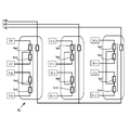
(1)例えば、図7に示すように、3相3巻線トランスA’は、一次巻線の相ごとにトランス鉄心を分割し、二次巻線と三次巻線を同一の鉄心に巻き付ける構成としてもよい。このような他の実施形態では、各相それぞれ二次巻線と三次巻線の鉄心を共通化するため、直流成分をキャンセルして、コンデンサの直流充放電電流による発生する直流磁束を、相互に打ち消し合うことが可能になる。このため、鉄心磁気飽和を防止して飽和磁束密度を小さくすることができ、トランス鉄心の更なる小型化が可能になる。
本発明の実施形態は、上記の形態には限定されない。
(1)例えば、図7に示すように、3相3巻線トランスA’は、一次巻線の相ごとにトランス鉄心を分割し、二次巻線と三次巻線を同一の鉄心に巻き付ける構成としてもよい。このような他の実施形態では、各相それぞれ二次巻線と三次巻線の鉄心を共通化するため、直流成分をキャンセルして、コンデンサの直流充放電電流による発生する直流磁束を、相互に打ち消し合うことが可能になる。このため、鉄心磁気飽和を防止して飽和磁束密度を小さくすることができ、トランス鉄心の更なる小型化が可能になる。
(2)3相3脚トランスAの各脚に一次1巻線、二次1巻線、三次1巻線とした構成にするようにしてもよい。これにより、上記の実施形態と同様、各相直流磁束が相互に打ち消すことができる。さらには、3相3脚鉄心化による通常3相トランスと同様の小型化も達成することが可能になる。
(3)上記の実施形態は、同様の構成によって、直流から交流の変換を行うこともできるし、反対に交流から直流の変換を行うことができる。つまり、本実施形態の電力変換装置は、インバータとしてもコンバータとしても構成することができる。
(4)本発明のいくつかの実施形態を説明したが、これらの実施形態は、例として提示したものであり、発明の範囲を限定することは意図していない。これら実施形態は、その他の様々な形態で実施されることが可能であり、発明の要旨を逸脱しない範囲で、種々の省略、置き換え、変更を行うことができる。これら実施形態やその変形は、発明の範囲や要旨に含まれると同様に、請求の範囲に記載された発明とその均等の範囲に含まれるものである。
A、A’…3相3巻線トランス
B…直流電源
C…単位ユニット
Up、Vp、Wp…正負側の単位アーム
Un、Vn、Wn…正負側の単位アーム
20…レグ
21U、21X…スイッチング素子
22U、22X…還流ダイオード
30…コンデンサ
B…直流電源
C…単位ユニット
Up、Vp、Wp…正負側の単位アーム
Un、Vn、Wn…正負側の単位アーム
20…レグ
21U、21X…スイッチング素子
22U、22X…還流ダイオード
30…コンデンサ
Claims (2)
- 二次巻線および三次巻線がそれぞれデルタ結線された3相3巻線トランスを備え、
前記3相3巻線トランスの二次巻線と三次巻線のそれぞれ同一相同士の各相巻線の中性点を互いに接続し、
さらに、自己消弧能力を持つスイッチング素子を直列に2個接続したレグとコンデンサとを並列に接続して単位ユニットとし、前記単位ユニットを直列に接続した正側および負側の単位アームを備え、
前記正側の単位アームは、一端を直流電源の正側に接続し、他の一端を前記3相3巻線トランスの二次巻線の各相出力端に接続し、
前記負側の単位アームは、一端を直流電源の負側に接続し、他の一端を前記3相3巻線トランスの三次巻線の各相出力端に接続したことを特徴とする電力変換装置。 - 前記3相3巻線トランスの一次巻線の相ごとにトランス鉄心を分割し、二次巻線と三次巻線を一つの鉄心に巻きつけたことを特徴とする請求項1に記載の電力変換装置。
Priority Applications (2)
| Application Number | Priority Date | Filing Date | Title |
|---|---|---|---|
| EP16740052.2A EP3249799B1 (en) | 2015-01-21 | 2016-01-14 | Power conversion device |
| CN201680004864.8A CN107148730B (zh) | 2015-01-21 | 2016-01-14 | 电力转换装置 |
Applications Claiming Priority (2)
| Application Number | Priority Date | Filing Date | Title |
|---|---|---|---|
| JP2015-009781 | 2015-01-21 | ||
| JP2015009781A JP6470051B2 (ja) | 2015-01-21 | 2015-01-21 | 電力変換装置 |
Publications (1)
| Publication Number | Publication Date |
|---|---|
| WO2016117445A1 true WO2016117445A1 (ja) | 2016-07-28 |
Family
ID=56416992
Family Applications (1)
| Application Number | Title | Priority Date | Filing Date |
|---|---|---|---|
| PCT/JP2016/050976 Ceased WO2016117445A1 (ja) | 2015-01-21 | 2016-01-14 | 電力変換装置 |
Country Status (4)
| Country | Link |
|---|---|
| EP (1) | EP3249799B1 (ja) |
| JP (1) | JP6470051B2 (ja) |
| CN (1) | CN107148730B (ja) |
| WO (1) | WO2016117445A1 (ja) |
Cited By (2)
| Publication number | Priority date | Publication date | Assignee | Title |
|---|---|---|---|---|
| WO2018154971A1 (ja) * | 2017-02-24 | 2018-08-30 | 株式会社 東芝 | 電力変換装置 |
| CN111880033A (zh) * | 2020-07-30 | 2020-11-03 | 中国南方电网有限责任公司超高压输电公司天生桥局 | 一种柔性直流功率模块测试设备及方法 |
Families Citing this family (3)
| Publication number | Priority date | Publication date | Assignee | Title |
|---|---|---|---|---|
| EP3516763B1 (de) | 2016-09-23 | 2022-10-12 | Wobben Properties GmbH | Verfahren zum erzeugen eines wechselstroms mittels eines wechselrichters einer windenergieanlage |
| KR101913746B1 (ko) * | 2017-08-28 | 2018-10-31 | 박찬희 | 주파수 및 전압 조절이 가능한 교류전력 발생기 |
| CN115552778A (zh) * | 2020-05-13 | 2022-12-30 | 崔又熹 | 非旋转式交流发电装置 |
Citations (3)
| Publication number | Priority date | Publication date | Assignee | Title |
|---|---|---|---|---|
| JP2001210533A (ja) * | 2000-01-21 | 2001-08-03 | Hitachi Ltd | 変圧器 |
| JP2013115837A (ja) * | 2011-11-24 | 2013-06-10 | Toshiba Corp | 電力変換装置 |
| WO2013108376A1 (ja) * | 2012-01-18 | 2013-07-25 | 東芝三菱電機産業システム株式会社 | 電力変換装置 |
Family Cites Families (2)
| Publication number | Priority date | Publication date | Assignee | Title |
|---|---|---|---|---|
| JP5894763B2 (ja) * | 2011-10-31 | 2016-03-30 | 株式会社日立製作所 | 電力変換装置 |
| EP2760122A1 (en) * | 2013-01-24 | 2014-07-30 | DET International Holding Limited | Cascaded H-Bridge Converter with transformer based cell power balancing in each voltage level |
-
2015
- 2015-01-21 JP JP2015009781A patent/JP6470051B2/ja active Active
-
2016
- 2016-01-14 EP EP16740052.2A patent/EP3249799B1/en active Active
- 2016-01-14 WO PCT/JP2016/050976 patent/WO2016117445A1/ja not_active Ceased
- 2016-01-14 CN CN201680004864.8A patent/CN107148730B/zh active Active
Patent Citations (3)
| Publication number | Priority date | Publication date | Assignee | Title |
|---|---|---|---|---|
| JP2001210533A (ja) * | 2000-01-21 | 2001-08-03 | Hitachi Ltd | 変圧器 |
| JP2013115837A (ja) * | 2011-11-24 | 2013-06-10 | Toshiba Corp | 電力変換装置 |
| WO2013108376A1 (ja) * | 2012-01-18 | 2013-07-25 | 東芝三菱電機産業システム株式会社 | 電力変換装置 |
Non-Patent Citations (1)
| Title |
|---|
| See also references of EP3249799A4 * |
Cited By (5)
| Publication number | Priority date | Publication date | Assignee | Title |
|---|---|---|---|---|
| WO2018154971A1 (ja) * | 2017-02-24 | 2018-08-30 | 株式会社 東芝 | 電力変換装置 |
| JP2018139470A (ja) * | 2017-02-24 | 2018-09-06 | 株式会社東芝 | 電力変換装置 |
| EP3588765A4 (en) * | 2017-02-24 | 2021-01-13 | Kabushiki Kaisha Toshiba | CURRENT CONVERSION DEVICE |
| CN111880033A (zh) * | 2020-07-30 | 2020-11-03 | 中国南方电网有限责任公司超高压输电公司天生桥局 | 一种柔性直流功率模块测试设备及方法 |
| CN111880033B (zh) * | 2020-07-30 | 2022-12-20 | 中国南方电网有限责任公司超高压输电公司天生桥局 | 一种柔性直流功率模块测试设备及方法 |
Also Published As
| Publication number | Publication date |
|---|---|
| EP3249799A1 (en) | 2017-11-29 |
| CN107148730B (zh) | 2019-09-03 |
| EP3249799A4 (en) | 2018-08-01 |
| JP2016135054A (ja) | 2016-07-25 |
| EP3249799B1 (en) | 2021-09-01 |
| JP6470051B2 (ja) | 2019-02-13 |
| CN107148730A (zh) | 2017-09-08 |
Similar Documents
| Publication | Publication Date | Title |
|---|---|---|
| JP5881386B2 (ja) | 電力変換装置 | |
| CN104685771B (zh) | 电力变换装置 | |
| US8299732B2 (en) | Power conversion system and method | |
| KR101425400B1 (ko) | 초고압직류송전용 컨버터 | |
| JP6289825B2 (ja) | 発電機励磁装置および電力変換システム | |
| JP6404768B2 (ja) | 電力変換装置 | |
| JP6470051B2 (ja) | 電力変換装置 | |
| US11909305B2 (en) | AC-to-DC power converter which removed a common mode component form the output current | |
| JP6104736B2 (ja) | 電力変換装置 | |
| JP6253258B2 (ja) | 電力変換装置 | |
| JP2008178180A (ja) | 整流回路 | |
| WO2019043758A1 (ja) | 電力変換装置、電力変換システム、および電力変換システムの使用方法 | |
| EP3742596B1 (en) | Power converter | |
| KR101520599B1 (ko) | 고조파 회생 변압기 | |
| US20220247307A1 (en) | Distorsion filter arrangement | |
| KR101133138B1 (ko) | 전원 컨버터 시스템 |
Legal Events
| Date | Code | Title | Description |
|---|---|---|---|
| 121 | Ep: the epo has been informed by wipo that ep was designated in this application |
Ref document number: 16740052 Country of ref document: EP Kind code of ref document: A1 |
|
| NENP | Non-entry into the national phase |
Ref country code: DE |
|
| REEP | Request for entry into the european phase |
Ref document number: 2016740052 Country of ref document: EP |