WO2016119511A1 - 永磁直驱风力发电机、系统及其定子 - Google Patents
永磁直驱风力发电机、系统及其定子 Download PDFInfo
- Publication number
- WO2016119511A1 WO2016119511A1 PCT/CN2015/094821 CN2015094821W WO2016119511A1 WO 2016119511 A1 WO2016119511 A1 WO 2016119511A1 CN 2015094821 W CN2015094821 W CN 2015094821W WO 2016119511 A1 WO2016119511 A1 WO 2016119511A1
- Authority
- WO
- WIPO (PCT)
- Prior art keywords
- stator
- air
- air hole
- air flow
- flow passage
- Prior art date
- Legal status (The legal status is an assumption and is not a legal conclusion. Google has not performed a legal analysis and makes no representation as to the accuracy of the status listed.)
- Ceased
Links
Images




Classifications
-
- H—ELECTRICITY
- H02—GENERATION; CONVERSION OR DISTRIBUTION OF ELECTRIC POWER
- H02K—DYNAMO-ELECTRIC MACHINES
- H02K9/00—Arrangements for cooling or ventilating
- H02K9/02—Arrangements for cooling or ventilating by ambient air flowing through the machine
- H02K9/04—Arrangements for cooling or ventilating by ambient air flowing through the machine having means for generating a flow of cooling medium
-
- F—MECHANICAL ENGINEERING; LIGHTING; HEATING; WEAPONS; BLASTING
- F03—MACHINES OR ENGINES FOR LIQUIDS; WIND, SPRING, OR WEIGHT MOTORS; PRODUCING MECHANICAL POWER OR A REACTIVE PROPULSIVE THRUST, NOT OTHERWISE PROVIDED FOR
- F03D—WIND MOTORS
- F03D80/00—Details, components or accessories not provided for in groups F03D1/00 - F03D17/00
- F03D80/60—Cooling or heating of wind motors
-
- F—MECHANICAL ENGINEERING; LIGHTING; HEATING; WEAPONS; BLASTING
- F03—MACHINES OR ENGINES FOR LIQUIDS; WIND, SPRING, OR WEIGHT MOTORS; PRODUCING MECHANICAL POWER OR A REACTIVE PROPULSIVE THRUST, NOT OTHERWISE PROVIDED FOR
- F03D—WIND MOTORS
- F03D9/00—Adaptations of wind motors for special use; Combinations of wind motors with apparatus driven thereby; Wind motors specially adapted for installation in particular locations
- F03D9/20—Wind motors characterised by the driven apparatus
- F03D9/25—Wind motors characterised by the driven apparatus the apparatus being an electrical generator
-
- H—ELECTRICITY
- H02—GENERATION; CONVERSION OR DISTRIBUTION OF ELECTRIC POWER
- H02K—DYNAMO-ELECTRIC MACHINES
- H02K1/00—Details of the magnetic circuit
- H02K1/06—Details of the magnetic circuit characterised by the shape, form or construction
- H02K1/12—Stationary parts of the magnetic circuit
- H02K1/18—Means for mounting or fastening magnetic stationary parts on to, or to, the stator structures
- H02K1/187—Means for mounting or fastening magnetic stationary parts on to, or to, the stator structures to inner stators
-
- H—ELECTRICITY
- H02—GENERATION; CONVERSION OR DISTRIBUTION OF ELECTRIC POWER
- H02K—DYNAMO-ELECTRIC MACHINES
- H02K1/00—Details of the magnetic circuit
- H02K1/06—Details of the magnetic circuit characterised by the shape, form or construction
- H02K1/12—Stationary parts of the magnetic circuit
- H02K1/20—Stationary parts of the magnetic circuit with channels or ducts for flow of cooling medium
-
- H—ELECTRICITY
- H02—GENERATION; CONVERSION OR DISTRIBUTION OF ELECTRIC POWER
- H02K—DYNAMO-ELECTRIC MACHINES
- H02K15/00—Processes or apparatus specially adapted for manufacturing, assembling, maintaining or repairing of dynamo-electric machines
- H02K15/12—Impregnating, moulding insulation, heating or drying of windings, stators, rotors or machines
- H02K15/125—Heating or drying of machines in operational state, e.g. standstill heating
-
- H—ELECTRICITY
- H02—GENERATION; CONVERSION OR DISTRIBUTION OF ELECTRIC POWER
- H02K—DYNAMO-ELECTRIC MACHINES
- H02K5/00—Casings; Enclosures; Supports
- H02K5/04—Casings or enclosures characterised by the shape, form or construction thereof
- H02K5/10—Casings or enclosures characterised by the shape, form or construction thereof with arrangements for protection from ingress, e.g. water or fingers
-
- H—ELECTRICITY
- H02—GENERATION; CONVERSION OR DISTRIBUTION OF ELECTRIC POWER
- H02K—DYNAMO-ELECTRIC MACHINES
- H02K7/00—Arrangements for handling mechanical energy structurally associated with dynamo-electric machines, e.g. structural association with mechanical driving motors or auxiliary dynamo-electric machines
- H02K7/18—Structural association of electric generators with mechanical driving motors, e.g. with turbines
- H02K7/1807—Rotary generators
- H02K7/1823—Rotary generators structurally associated with turbines or similar engines
- H02K7/183—Rotary generators structurally associated with turbines or similar engines wherein the turbine is a wind turbine
- H02K7/1838—Generators mounted in a nacelle or similar structure of a horizontal axis wind turbine
-
- H—ELECTRICITY
- H02—GENERATION; CONVERSION OR DISTRIBUTION OF ELECTRIC POWER
- H02K—DYNAMO-ELECTRIC MACHINES
- H02K9/00—Arrangements for cooling or ventilating
- H02K9/08—Arrangements for cooling or ventilating by gaseous cooling medium circulating wholly within the machine casing
-
- F—MECHANICAL ENGINEERING; LIGHTING; HEATING; WEAPONS; BLASTING
- F05—INDEXING SCHEMES RELATING TO ENGINES OR PUMPS IN VARIOUS SUBCLASSES OF CLASSES F01-F04
- F05B—INDEXING SCHEME RELATING TO WIND, SPRING, WEIGHT, INERTIA OR LIKE MOTORS, TO MACHINES OR ENGINES FOR LIQUIDS COVERED BY SUBCLASSES F03B, F03D AND F03G
- F05B2220/00—Application
- F05B2220/70—Application in combination with
- F05B2220/706—Application in combination with an electrical generator
- F05B2220/7068—Application in combination with an electrical generator equipped with permanent magnets
-
- H—ELECTRICITY
- H02—GENERATION; CONVERSION OR DISTRIBUTION OF ELECTRIC POWER
- H02K—DYNAMO-ELECTRIC MACHINES
- H02K5/00—Casings; Enclosures; Supports
- H02K5/04—Casings or enclosures characterised by the shape, form or construction thereof
- H02K5/20—Casings or enclosures characterised by the shape, form or construction thereof with channels or ducts for flow of cooling medium
- H02K5/207—Casings or enclosures characterised by the shape, form or construction thereof with channels or ducts for flow of cooling medium with openings in the casing specially adapted for ambient air
-
- H—ELECTRICITY
- H02—GENERATION; CONVERSION OR DISTRIBUTION OF ELECTRIC POWER
- H02K—DYNAMO-ELECTRIC MACHINES
- H02K9/00—Arrangements for cooling or ventilating
- H02K9/02—Arrangements for cooling or ventilating by ambient air flowing through the machine
-
- Y—GENERAL TAGGING OF NEW TECHNOLOGICAL DEVELOPMENTS; GENERAL TAGGING OF CROSS-SECTIONAL TECHNOLOGIES SPANNING OVER SEVERAL SECTIONS OF THE IPC; TECHNICAL SUBJECTS COVERED BY FORMER USPC CROSS-REFERENCE ART COLLECTIONS [XRACs] AND DIGESTS
- Y02—TECHNOLOGIES OR APPLICATIONS FOR MITIGATION OR ADAPTATION AGAINST CLIMATE CHANGE
- Y02E—REDUCTION OF GREENHOUSE GAS [GHG] EMISSIONS, RELATED TO ENERGY GENERATION, TRANSMISSION OR DISTRIBUTION
- Y02E10/00—Energy generation through renewable energy sources
- Y02E10/70—Wind energy
- Y02E10/72—Wind turbines with rotation axis in wind direction
Definitions
- the invention belongs to the technical field of wind power, and particularly relates to a permanent magnet direct drive wind power generator, a system and a stator thereof.
- the open type permanent magnet direct drive outer rotor wind power generator relies on natural air cooling, the opening structure is favorable for natural ventilation heat exchange, and the magnetic pole uses the permanent magnet material to prevent the magnetic reduction after the temperature rise exceeds the standard, but the generator is usually exposed. In extremely harsh environments (exposure to wind, frost, rain, snow, sand, salt spray, etc.).
- Air-cooled generator insulation is susceptible to moisture due to its operating state and structure. Because the insulation of the generator can only be embedded in the core groove, it can not be immersed in the insulating oil like a transformer, nor can it be sealed in a sealed metal casing filled with SF6 like the GIS of the fully enclosed combination GIS. The insulation of the generator can only be exposed to the air. During normal operation, the heat generated by the generator core and windings is carried away by the flowing air. When the generator heat and heat dissipation are balanced, the generator core and winding temperature are kept within a certain range of values.
- the internal rotor of the permanent magnet direct-drive generator that relies on natural air-cooling also relies on the air invading from nature to act as a cooling medium.
- the core and winding temperature will be higher than the temperature of the cooling medium air. After the generator is stopped, the core and winding temperature will gradually decrease. Due to the air expansion and contraction in the air gap and air gap, a large amount of air enters the generator to reach the pressure. balance. At this time, the insulation absorbs the moisture in the air and gets wet. If the air humidity is greater after the rainstorm season, the insulation of the generator is more severe.
- the leakage current is several tens or even hundreds of times the normal value, and the insulation resistance is one-tenth of the normal value.
- the generator insulation is very wet, and it cannot be operated without drying.
- the insulation of the generator is severely affected by the insulation test data. In fact, in the initial stage of insulation and moisture, only the surface adsorbs moisture, and the inside of the insulation has not been damp. Compared with the insulation after being immersed in water, the moisture on the insulating surface is still trace amount, and it is much easier to dry.
- thermal power generator sets, hydroelectric generating sets, and nuclear power units operating in the power grid are usually installed in a fixed building.
- the plant will not be exposed to rain or snow.
- the cooling medium (water) used in the above-mentioned generator set will be more convenient to maintain the operating conditions of the ground-operated generator set than in the case of leakage. Wind turbines on or off the sea.
- generator cooling while taking full advantage of the convenience and superior performance conditions of air cooling in the natural environment, it is the insulation level of the insulation system of the generator that needs to be solved and tested.
- Permanent magnet direct-drive external rotor wind turbines are exposed to the freezing environment of wind, sand, rain, snow, sun exposure or shutdown, and turbine generators, gas turbine generators and hydroelectric generators running on the ground.
- the environmental gap is too large, especially the cost of repair work is too high, and the use of aerial work (60-120 m) cranes requires high fees. So it is even impossible to work on the ground easily into wind turbines.
- operations in wind turbines also rely on windy weather.
- the wind turbine drives the rotor of the generator to rotate, and the generator stator induces an electric potential to implement a three-phase short circuit at the stator outlet, and the stator is cooled by the short-circuit current to heat the stator to improve the insulation level.
- the pitch control is indirectly controlled to control the rotor speed of the generator, thereby controlling the short-circuit current and controlling the heat generation of the windings to dry the tide.
- These conditions depend on the weather.
- the duration of the wind affects the drying effect.
- the direct-drive outer rotor permanent magnet wind turbine has a large mass and requires a large amount of heat production.
- the heat transfer time after heat generation and the mass transfer drying time at the time of flooding are several orders of magnitude. The duration and duration of the wind affect the drying effect.
- Permanent magnet direct drive outer rotor wind turbine uses natural wind to cool the stator core bracket and the outer wall of the rotor, while a certain amount of wind in the natural environment invades the motor cavity through the generator stator rotor gap, and then the air gap along the shaft The flow is concentrated to the other end, and the deposited light is discharged from the rear end and discharged into the atmosphere.
- Flowing through the internal gap of the motor is a gas (steam), liquid, solid multiphase flow (including air, water vapor, rain, snow, salt spray, dust, floc, etc.). They can cause deterioration of insulation performance, resulting in deterioration of electrical insulation properties and mechanical properties of the motor, and residual pressure levels. And the life is reduced, eventually leading to the destruction of insulation.
- the object of the embodiments of the present invention is to provide a permanent magnet direct drive wind power generator, a system and a stator thereof, which can introduce the airflow inside the stator bracket to the axial end surface of the stator core, thereby facilitating the motor to use the airflow disposed inside.
- the source dries itself, or resists the harsh external airflow (such as rain or snow), making it difficult to enter the inside of the motor, prolonging the service life of the permanent magnet pole, preventing the internal insulation of the motor from "insulation level", reducing the risk of moisture corrosion of the motor and making the motor Insulation reliability can be guaranteed.
- an embodiment of the present invention provides a stator for a permanent magnet direct drive wind power generator, including a stator bracket, a stator core disposed on an outer peripheral wall of the stator bracket, and a paddle side tooth pressing plate, and the paddle side tooth pressing plate Provided on the paddle-side axial end surface of the stator core, at least one first air hole is formed on the outer peripheral wall of the stator bracket, and at least one second air hole is opened on the paddle side pressure plate, the stator The method further includes at least one air flow passage connecting the first air hole and the second air hole, the air flow path passing through an interior of the stator core.
- embodiments of the present invention also provide another permanent magnet direct drive wind turbine a stator support, a stator core disposed on an outer peripheral wall of the stator bracket, a paddle side tooth plate, and a tower side tooth plate, the paddle side pressure plate being disposed on a paddle side axial end surface of the stator core, the tower The side tooth pressing plate is disposed on the tower side axial end surface of the stator core, and at least one first air hole is opened on the outer peripheral wall of the stator bracket, and at least one second air hole is opened on the paddle side tooth pressing plate.
- At least one third air hole is defined in the tower side tooth pressure plate, and the stator further includes at least one air flow channel connecting the first air hole with the second air hole and the third air hole, the air flow channel Passing through the interior of the stator core.
- Embodiments of the present invention also provide a permanent magnet direct drive wind power generator including a rotor and a stator as described above.
- an embodiment of the present invention further provides a stator for a permanent magnet direct drive wind power generator, comprising a stator bracket, a stator core disposed on an outer peripheral wall of the stator bracket, and a tower side tooth pressing plate, wherein the tower side tooth pressing plate is disposed At least one first air hole is formed in the outer peripheral wall of the stator bracket on the axial side end surface of the stator core, and at least one third air hole is opened on the tower side tooth pressure plate, and the stator is further And including at least one air flow passage connecting the first air hole and the third air hole, the air flow passage passing through an inner portion of the stator core.
- Embodiments of the present invention also provide another permanent magnet direct drive wind power generator including a rotor and a stator as described above.
- Embodiments of the present invention also provide a permanent magnet direct drive wind power generator system including the wind power generator as described above and a gas source system disposed inside the wind turbine, the air source system being coupled to the first air hole .
- the permanent magnet direct drive wind power generator, the system and the stator thereof of the embodiment of the invention can introduce the air flow inside the stator into the axial end surface of the stator core, so that the motor can dry and cool itself by using the air source disposed inside. Or it can resist the harsh airflow (such as rain or snow) from entering the inside of the motor, which can prolong the service life of the permanent magnet pole, prevent the internal insulation of the motor from “insulation level”, and reduce the motor's exposure to harsh airflow (such as rain or snow). The risk and reliability of insulation can be guaranteed.
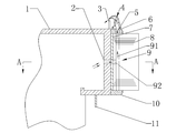
- FIG. 1 is a schematic structural view of a stator of a permanent magnet direct drive wind power generator according to Embodiment 1 of the present invention
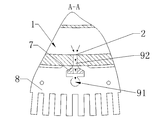
- Figure 2 is a schematic cross-sectional view taken along line A-A of Figure 1;
- FIG. 3 is a schematic diagram of an air flow path inside a stator core of a permanent magnet direct drive wind power generator according to Embodiment 1 of the present invention
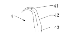
- FIG. 4 is a schematic structural view of a tapered nozzle disposed in a permanent magnet direct drive wind power generator according to Embodiment 1 of the present invention
- FIG. 5 is a flow path of obtaining airflow in a stator of a permanent magnet direct-drive wind power generator according to Embodiment 1 of the present invention
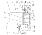
- FIG. 6 is a schematic structural view of a stator and a rotor joint portion of a generator according to Embodiment 1 of the present invention.
- FIG. 7 is a schematic structural view of a stator and a rotor joint portion of a permanent magnet direct drive wind power generator according to a second embodiment of the present invention.
- FIG. 8 is a schematic view showing the overall structure of a permanent magnet direct drive wind power generator according to a second embodiment of the present invention.
- Fig. 9 is a structural schematic view showing a stator-rotor coupling portion of a permanent magnet direct-drive wind power generator according to a third embodiment of the present invention.
- 1-stator bracket 2-first air hole; 3-blade side wall; 4-throwing nozzle; 41-bend section; 42-sloping section; 43-vertical section; 5-second air hole; Side tooth pressure plate; 7-punching plate fixing key; 8- stator core; 9-air flow passage; 91-axial passage; 92-radial passage; 10-tower side pressure plate; 11-tower side coaming; Source system; 13-mother tube; 14-branch tube; 15-rotor bracket; 16-rotor seal ring; 17-winding; 18-pole; 19-rotor end cap; 20-end cap seal ring; 21-third air hole; 22-Tower side seal.
- the technical principle of the embodiment of the present invention is to introduce the internal air source of the unit into the axial end surface of the stator core by using the air flow passage in the stator core of the permanent magnet direct drive wind power generator, so that the air flow is formed after the stator and the rotor of the fan are combined. Construct a micro-positive pressure environment in the internal space, using micro-positive pressure airflow to withstand the harsh external airflow (gas, liquid, solid multiphase flow, including air, water vapor, rain, snow, salt spray, sand dust, floc Etc.).
- the micro-positive pressure is that the internal airflow or the ambient pressure is greater than the external environment, so that the external airflow cannot enter the motor.
- the above-mentioned severe airflow mainly refers to rainwater gas-liquid two-phase flow or wind-snow gas-solid two-phase flow.
- gas, liquid and solid multiphase flows in extreme cases, such as air, water vapor, rain, snow, Salt spray, sand dust, floc, etc.
- These severe airflows mainly occur in severe weather conditions such as rain or snow. Therefore, the apparatus of the embodiment of the present invention is mainly designed to withstand these severe airflows, and in normal dry weather, the embodiment of the present invention may not be used.
- the device allows the dry gas stream to enter the wind turbine for drying and cooling the fan.
- FIG. 1 is a schematic structural view of a stator of a permanent magnet direct drive wind power generator according to Embodiment 1 of the present invention.
- the upper part in Fig. 1 can be defined as the paddle side (the blade side generally faces the upwind side during the operation of the fan), and the lower side is defined as the tower side (in the process of the fan operation, the tower side generally Facing the downwind side), the horizontal direction is defined as the radial direction (the radial direction centered on the entire fan), and the vertical direction is defined as the axial direction (the direction along the axis of the wind turbine).
- the outer peripheral wall of the stator holder refers to a side wall that is in contact with or adjacent to the stator core or the fixed fixing key of the stator core, that is, the outermost portion of the stator holder.
- the stator of the permanent magnet direct drive wind power generator of the present embodiment includes a stator bracket 1, a stator core 8 disposed on the outer peripheral wall of the stator bracket 1, and a paddle side tooth plate 6, and the paddle side tooth plate 6 is disposed on the paddle shaft of the stator core 8.
- the stator support is cylindrical, so that at least one first air hole 2 can be opened on the outer peripheral wall of the stator support 1, and at least one second air hole 5 can be opened on the paddle side pressure plate 6.
- the stator may further include at least one air flow passage 9 that communicates the first air hole 2 and the second air hole 5, and the air flow path 9 may pass through the inside of the stator core 8.
- the first air hole 2 and the second air hole 5 may be circular or triangular or elliptical. Further, the air holes may be air holes of other shapes or the like, and as long as the air flow can be conducted. Preferably, the first air hole 2 and the second air hole 5 are circular air holes, and the circular air holes can reduce the flow resistance to the air flow.
- the airflow inside the stator can be introduced to the end surface of the paddle side tooth plate 6 of the stator core, so that on the paddle side of the wind power generator, the wind turbine can dry, cool or use itself by using the air source installed inside. Resist the harsh airflow (such as rain or snow), making it difficult to enter the inside of the motor, thus extending the life of the permanent magnet pole and preventing it
- the internal components of the motor "lower insulation level” reduce the risk of the motor being eroded by harsh airflow (such as rain or snow) and ensure insulation reliability.
- annular tapered nozzle 4 may be provided on the paddle side tooth pressing plate 6 to control the airflow drawn from the inside of the stator for drying the fan or for resisting external airflow.
- the air flow passage 9 inside the stator core 8 is used to introduce the air flow of the air source 12 inside the stator to the at least one second air hole 5 opened in the paddle side tooth pressure plate 6.
- FIG. 2 which is a schematic view of the air flow passage taken along the AA section in FIG. 1
- a punch fixing key 7 is fixed on the outer peripheral wall of the stator bracket 1
- the stator core 8 (the stator core is composed of a multi-lobed core)
- the modules are assembled, each core module is composed of a core lamination, and has a dovetail groove which is sleeved on the punch fixing key 7, thereby fixing the stator core 8 to the outer peripheral wall of the stator holder 1.
- the first air hole 2 may be located on the outer peripheral wall of the stator holder 1 which is in contact with the punch fixing key 7, and the air flow path 9 may communicate with the first air hole 2 through the air hole of the punch fixing key 7.
- the air flow passage 9 may include a radial air flow passage 92 and an axial air flow passage 91, and the radial air flow passage 92 may pass through the inside of the punch fixing key 7 and the stator core 8, one end of the radial air flow passage 92
- the first air hole 2 is connected to the first air hole 2, and the other end is connected to the axial air flow path 91.
- the axial air flow path 91 can communicate with the second air hole 5 through the inside of the stator core 8 in the axial direction.
- the radial air flow passage 92 and the axial air flow passage 91 may be directly connected or may be connected after being bent anyway. In short, the radial air flow passage 92 and the axial air flow passage 91 may be connected.
- first air hole 2, the second air hole 5, and the air flow path 9 may be plural and equal in number, and are equally disposed along the circumference.
- the plurality of first air holes 2, the second air holes 5 and the air flow channel 9 are correspondingly connected to each other to form a plurality of independent air flow paths from the inner wall of the stator support 1 to the paddle side pressure plate 6.
- the radial air flow passage 92 is turned 90 degrees inside the stator core 8 into the axial air flow passage 91, which is parallel to the stator axial direction of the motor. As shown in FIG.
- FIG. 3 it is a schematic diagram of an airflow path inside a stator core of a permanent magnet direct-drive wind power generator according to Embodiment 1 of the present invention, wherein the radial airflow passages are in one-to-one correspondence with the axial airflow passages, and only the figure is shown in the figure.
- the axial air flow passage, the embodiment of the present invention has a plurality of air flow passages.
- a total of 48 air flow passages are provided, the lengths thereof (L 1 , L 2 ... L 48 ) / inner diameter ( d 1 , d 2 ... d 48 ) / absolute roughness ( ⁇ 1 , ⁇ 2 ... ⁇ 48 ) are preferably the same, and the circumferential intervals are also uniform.
- the outlet of the tapered nozzle 4 can face the gap between the stator and the rotor.
- the tapered nozzle 4 can accelerate the airflow and form a micro-positive pressure airflow at the gap between the stator and the rotor to actively resist the rain and snow.
- FIG. 4 it is a schematic structural view of a tapered nozzle of a permanent magnet direct drive wind power generator according to Embodiment 1 of the present invention; an annular tapered nozzle 4 may be disposed on the paddle side tooth pressing plate 6 (i.e., disposed along the circumferential direction of the stator as a whole), the second air hole 5 communicates with the annular inlet of the tapered nozzle 4, and the gas in the air flow passage 9 inside the stator core 8 can be introduced into the tapered nozzle 4.
- the stator may comprise a paddle side panel 3
- the rotor may comprise a rotor seal ring 16, after the stator and rotor are combined and mounted
- the annular outlet of the tapered nozzle 4 can face the annular gap formed by the paddle shroud 3 and the rotor seal ring 16. It is used to seal the annular gap formed between the paddle side panel 3 and the rotor seal ring 16.
- the tapered nozzle 4 can be formed as a one-piece annular nozzle that is tightly buckled at at least one second air hole 5 of the paddle side panel 3
- the tapered nozzle 4 is seamlessly connected to the second air hole 5, so that the gas flowing out of each of the second air holes 5 is sufficiently converged and the pressure of the air flow is uniformized, and an equal pressure is formed at the exit of the tapered nozzle 4.
- the Bernoulli equation (energy equation) of the actual fluid flow in the fluid mechanics is used to analyze the upwind air flow carrying rainwater (or snow) after the wind turbine is blocked, after passing through the stator.
- the annular gap between the paddle side wall 3 and the rotor seal ring 16 (the coaming plate) is closed, the rainwater gas-liquid two-phase flow or the wind-air gas-solid two-phase flow (referred to as the external harsh air flow) is generated before and after the windward of the generator to the annular gap.
- the pressure and flow rate change to obtain the pressure and flow rate of the external harsh airflow into the annular gap.
- the pressure and flow rate of the airflow sealing jet element, the annular tapered nozzle outlet flow are calculated here.
- the pressure and flow rate of the outlet gas stream of the annular tapered nozzle 4 need only be slightly higher than the pressure and flow rate of the external harsh gas stream entering the annular gap. More preferably, the pressure and flow rate of the outlet gas flow of the annular tapered nozzle 4 is higher than about 3% to 5% of the pressure and flow rate of the external harsh gas flow.
- Air flow rate according to the principle of continuity of fluid flow, the outlet air flow rate of the air compressor for supplying the air source should be equal to the air flow rate required for the outlet of the tapered nozzle 4, thereby determining the outlet flow rate of the air compressor .
- the pressure of the outlet airflow of the air compressor for supplying the air source should be the same as the required pressure of the outlet airflow of the annular tapered nozzle 4, plus each from the gas source to the nozzle outlet.
- the sum of the total pressure drop of the link is the same, wherein the pressure drop includes the resistance along the path and the local resistance.
- the pressure at the outlet of the tapered nozzle 4 needs to be slightly higher than the pressure of the external harsh airflow entering the annular gap, after determining the pressure at the outlet of the tapered nozzle 4 And, after the total pressure drop from the gas source to the nozzle outlet (this can be obtained by theoretical calculation or measurement according to the structure of the gas flow passage and the tapered nozzle), the outlet flow of the air compressor can be determined. pressure.
- the cross section of the tapered nozzle 4 may be in the shape of a sickle, and may include a vertical section 43 that is sequentially connected, a sloped section 42 and a curved section 41.
- the vertical section 43 communicates with the second air hole 5, and the diameter of the vertical section 43
- the width direction is uniform and greater than or equal to the radial width of the second air hole 5, the inclined portion 42 is entirely inclined toward the center of the stator, and the curved portion 41 is formed in an arc shape as a whole, and the end thereof forms an exit of the tapered nozzle 4 from the inclination. From the end of the segment 42 to the curved portion 41, the radial width is gradually reduced.
- the flow of gas through the tapered nozzle 4 converts the pressure energy of the gas stream into the kinetic energy of the gas stream.
- the tapered nozzle 4 relies on sufficient pressure provided by a source of gas (e.g., an air compressor) to produce a high velocity gas stream, and the outlet flow rate, flow rate is controllable to accommodate changes in the wind speed of the paddle side. That is: the pressure of the air pressure seal can be automatically adjusted as needed to achieve "adaptive" adjustment, thereby reducing the power consumption of the air compressor as a gas source and saving energy.
- a source of gas e.g., an air compressor
- the tapered nozzle outlet faces the annular gap between the stator and the rotor, a micro-positive pressure barrier is formed between the interior of the motor and the external environment. It can actively resist the intrusion of “gas-liquid two-phase flow” or “gas-solid two-phase flow” during rain and snow weather, and accumulates a large amount of dry air in the motor and is extruded by micro-positive pressure, thereby eliminating the humid air flow outside the motor, thus making it possible to eliminate the humid air flow outside the motor.
- the winding surface and the permanent magnetic pole surface protective coating meet the drying requirements, which reduces the risk of moisture erosion caused by rain or snow melting, and improves the insulation reliability.
- the air source in the air supply system 12 inside the wind turbine may be taken from a pneumatic generating device in the nacelle.
- the gas source system 12 can withstand the intrusion of wind and rain "gas-liquid two-phase flow” and wind and snow "gas-solid two-phase flow” during rain and snow weather; the gas source system 12 works during the time period required to dry the motor, so that it is sufficient Drying the generator stator insulation and the rotor pole protection layer reduces the energy consumption of the air source.
- the air flow passage 9 provided in the stator is connected to the air supply system 12 through the first air hole 2, and the air source inside the wind turbine is led into the air flow passage 9.
- the gas source system 12 may include a gas source generating device that generates a predetermined pressure gas stream and a gas source processing device that can purify and dry the gas stream.
- the gas source generating device may be an air compressor, and the air compressor (or compressor) is a gas pressure generating device, which is a machine for increasing the pressure of the air or conveying the air, and is also a kind of converting the mechanical energy supplied by the prime mover into the air pressure energy. Conversion device.
- the air compressor or compressor
- the air in the cylinder of the compressor is rapidly compressed, and the process of rapidly compressing the gas is an exothermic process, which inevitably causes the temperature of the cylinder of the compressor to rise, and therefore, cooling is generally required.
- the exhaust temperature can reach 140-170 °C. At such high temperature, compressed air is often mixed with certain gaseous oil and water vapor.
- the gas source treatment device may further include an air filter, a cooler, a water separator, and a dryer.
- the air filter is used to filter the gas before entering the air compressor cylinder (ie, the dust and other impurities contained in the air in the filter cabin), and is used to prevent dust, solid impurities, etc. in the air from entering the air compressor, resulting in air. Friction and wear of relatively moving parts in the compressor cylinder.
- a water separator gas-liquid separator
- gas-liquid separator is used for further separation of compressed air
- the compressed air passes through the cooler and the water separator, it still contains a certain amount of water, and its content depends on the temperature, pressure and relative humidity of the air. Dry air is required in the motor, so an air drying device, that is, a dryer, is required.
- FIG. 5 it is a stator airflow acquisition path of the permanent magnet direct drive wind power generator according to the first embodiment of the present invention, and the air source system 12 can be connected to the first air hole 2 through the mother pipe 13 and the branch pipe 14.
- the branch pipe 14 having the same number as the first air hole 2 can be taken out from the mother pipe 13, and the branch pipe 14 is correspondingly connected to the first air hole 2.
- the mother tube 13 is preferably circular or segmented, so that the resistance to the flow of the airflow can be reduced.
- FIG. 6 is a schematic structural view of a stator and a rotor coupling portion of a generator according to Embodiment 1 of the present invention.
- the small arrows shown in the figure represent the flow path of the airflow.
- the airflow in the cabin is filtered and dried by the air source system 12, and then sent to the first air hole 2 on the stator support 1, and the airflow enters the radial airflow of the stator core 8 through the first air hole 2 through the punch fixing key 7.
- the airflow is transferred to the axial airflow passage 91 along the radial airflow passage 92, and then passes through the axial airflow passage 91 through the paddle side tooth pressure plate 6, into the tapered nozzle 4, and is accelerated by the tapered nozzle 4
- the outlet of the tapered nozzle 4 is sprayed out, and is blown to the annular gap between the paddle side wall 3 and the rotor seal ring 16, thereby blocking the annular rotating gap, preventing rain and snow gas-solid two-phase flow or rain water and liquid. The intrusion of two-phase flow.
- the paddle side is generally facing upwind, and the upwind flow impinges on the generator stator bracket to rebound and sputter, and then collides with the rotor seal ring to reflect and accumulate, causing airflow pressure recovery.
- This increase in airflow (compared to the incoming flow) will invade into the annular air gap between the paddle shroud 3 and the rotor seal ring 16.
- the airflow ejected by the tapered nozzle 4 of the embodiment of the present invention is used to block the intrusion of the above airflow.
- a permanent magnet direct drive wind power generator which comprises a rotor and a stator as provided in this embodiment.
- the first embodiment further provides a permanent magnet direct drive wind power generator system, which includes the wind power generator and the air source system 12 disposed inside the wind turbine, and the air source system 12 can be connected to the first air hole 2 .
- a permanent magnet direct drive wind power generator system which includes the wind power generator and the air source system 12 disposed inside the wind turbine, and the air source system 12 can be connected to the first air hole 2 .
- the air source system 12 and the components associated with the air source system 12 are also described above, and are not described herein again.
- FIG. 7 is a structural diagram of the stator and rotor joint portion of the permanent magnet direct drive wind power generator according to the second embodiment of the present invention.
- FIG. 8 is a schematic view showing the overall structure of a permanent magnet direct drive wind power generator according to a second embodiment of the present invention.
- the right side of the figure may be defined as the paddle side
- the left side is defined as the tower side
- the vertical direction is defined as the radial direction (the radial direction centered on the entire fan)
- the horizontal direction is defined as the axial direction (the horizontal direction is defined as the axial direction (the radial direction is centered on the entire fan)
- the small arrows shown in the figure represent the flow path of the airflow.
- the stator of the present embodiment includes a stator holder 1, a stator core 8 provided on the outer peripheral wall of the stator holder 1, a paddle side tooth plate 6 and a tower side tooth plate 10, and the paddle side tooth plate 6 is disposed on the paddle side axial end surface of the stator core 8.
- Upper, the tower side tooth pressing plate 10 is disposed on the tower side axial end surface of the stator core 8.
- At least one first air hole 2 is opened in the outer peripheral wall of the stator holder 1, and at least one second air hole 5 is opened in the paddle side pressure plate 6, and at least one third air hole 21 is opened in the tower side tooth pressing plate 10.
- the stator further includes at least one air flow passage 9 that communicates the first air hole 2 with the second air hole 5 and the third air hole 21, and the air flow path 9 passes through the inside of the stator core.
- the third air hole 21 is similar to the first air hole 2 and the second air hole 5, and may be circular or triangular or elliptical.
- the third air hole 21 air hole may also be other shapes of air guiding holes, etc., in general, as long as the air flow can be conducted, preferably, the third air hole 21 is a circular air hole, and the circular air hole can reduce the flow of the air flow. Resistance.
- the airflow inside the stator can be introduced to the paddle teeth of the stator core
- the end plate of the pressure plate 6 and the tower side tooth pressure plate 10 so that on the paddle side and the tower side of the wind power generator, the wind power generator can use the air source source disposed inside to dry, cool or resist the bad air flow to make it difficult to enter.
- the inside of the motor can extend the service life of the permanent magnet pole, prevent the internal insulation of the motor from “lower insulation level”, reduce the risk of the motor being eroded by harsh airflow (such as rain or snow) and ensure the insulation reliability.
- annular tapered nozzle 4 may be disposed on the paddle side tooth pressing plate 6 and the tower side tooth pressing plate 10, thereby controlling the airflow drawn from the inside of the stator for drying the fan, Cooled or used to withstand harsh outside airflow.
- the air flow passage 9 inside the stator core 8 is used to introduce a gas source inside the stator into at least one second air hole 5 opened in the paddle side tooth pressure plate 6 and at least one third air hole 21 opened in the tower side tooth pressure plate 10.
- a punching plate fixing key 7 is fixed on the outer peripheral wall of the stator holder 1.
- the stator core 8 has a dovetail groove, and the dovetail groove is sleeved on the punch fixing key 7, thereby fixing the stator core 8 to the stator.
- the first air hole 2 may be located on the outer peripheral wall of the stator holder 1 which is in contact with the punch fixing key 7.
- the punch fixing key 7 may be provided with air holes, and the air flow passage 9 may pass through the air hole of the punch fixing key 7 and the first air hole. 2 Unicom.
- the air flow passage 9 may include a radial air flow passage 92 and an axial air flow passage 91, and the radial air flow passage 92 may pass through the inside of the punch fixing key 7 and the stator core 8, One end of the radial air flow passage 92 is connected to the first air hole 2, and the other end is connected to the axial air flow passage 91.
- the first embodiment is different from the first embodiment in that the axial air flow passage 91 can pass through the inside of the stator core 8 in the axial direction.
- the second air hole 5 and the third air hole 21 are in communication.
- first air hole 2, the second air hole 5, the third air hole 21, and the air flow channel 9 may be plural and equal in number, and are equally disposed along the circumference, wherein the plurality of first air holes 2, the second air holes 5, and the third The air hole 21 and the air flow path 9 are correspondingly connected to each other to form a plurality of independent air flow paths 9 from the inner wall of the stator holder 1 to the paddle side pressure plate 6 and the tower side tooth plate 10.
- the tapered nozzle 4 having the same structure as that of the first embodiment may be provided, but the tapered nozzle 4 of the first embodiment is disposed on one side of the motor, and in the embodiment, the tapered nozzle 4 is provided. Set on both sides of the motor. Specifically, in the present embodiment, an annular tapered nozzle 4 is disposed on the paddle side tooth pressing plate 6 and the tower side tooth pressing plate 10, respectively, and the second air hole 5 and the third air hole 21 are respectively tapered with the corresponding side.
- the annular inlet of the tube is connected, that is, the second air hole 5 on the paddle side pressure plate 6 is in communication with the inlet of the paddle side tapered nozzle 4, the third air hole 21 on the tower side tooth pressure plate 10 and the tower side tapered nozzle 4
- the annular inlet is connected so that the gas in the gas flow passage 9 inside the stator core 8 can be introduced into the tapered nozzle 4.
- the stator may include a paddle side panel 3
- the rotor may include a rotor seal ring 16 in combination with the stator and rotor
- the outlet of the tapered nozzle 4 disposed on the paddle side pressure plate 6 may face the gap formed by the paddle side wall 3 and the rotor seal ring 16. It is used to seal the annular gap formed between the paddle side panel 3 and the rotor seal ring 16.
- the paddle side panel 3 and the rotor seal ring 16 are both annular.
- the stator may further comprise a tower side panel 11 which may comprise a rotor seal ring 16 and an end cap seal ring 20, After the stator and the rotor are assembled in combination, the outlet of the tapered nozzle 4 disposed on the tower side tooth pressure plate 10 faces the slit formed by the tower side wall 11 and the end cap sealing ring 20 for sealing the tower side panel 11 An annular gap formed between the end cap seal ring 20.
- the tapered nozzle 4 can be formed as a one-piece annular nozzle, tightly buckled on the paddle side panel 3 and The at least one second air hole 5 and the third air hole 21 on the tower side tooth pressure plate 10 are such that the tapered nozzle 4 and the second air hole 5 are seamlessly connected, so that the gas flowing out from each of the second air holes 5 is fully converge and the air flow is made.
- the pressure is uniform and equal pressure is formed at the outlet of the tapered nozzle 4.
- the radial section of the tapered nozzle 4 may be in the shape of a sickle, and may include a vertical section 43, a sloped section 42, and a curved section 41 which are sequentially connected.
- the vertical sections 43 of the tapered nozzles 4 disposed on the paddle side tooth pressing plate 6 and the tower side tooth pressing plate 10 are in communication with the second air hole 5 and the third air hole 21, respectively, that is, the paddle side tapered nozzle 4
- the vertical section 43 communicates with the second air hole 5, and the vertical section 43 of the tapered nozzle 4 on the tower side communicates with the third air hole 21.
- the vertical width of the vertical section 43 is uniform and greater than or equal to the second air hole 5 and The radial width of the three air holes 21.
- the inclined section 42 is entirely inclined toward the center of the stator, and the curved section 41 has an arc shape as a whole, and the end thereof forms an outlet of the tapered nozzle, and the radial width gradually decreases from the inclined section 42 to the end of the curved section 41.
- the structure and related components of the air source system 12 are the same as in the first embodiment.
- the small arrow shown in the figure represents the flow path of the airflow, and the airflow in the cabin is filtered and dried by the air source system 12, and then sent to the first air hole 2 on the stator support 1, and the air flow is
- the first air hole 2 enters the radial air flow passage 92 of the stator core 8 through the punch fixing key 7, and the air flow is transferred to the axial air flow passage 91 along the radial air flow passage 92, and then the axial air flow passage 91 passes through the paddle side tooth pressure plate.
- the air flow path formed in the first embodiment is used to block the external harsh airflow (the airflow invading from the paddle side) invading from the annular air gap between the paddle panel 3 and the rotor seal ring 16, and this embodiment
- the air flow path formed by the structure can also block the external harsh airflow (the airflow invading from the tower side) intruding from the annular gap between the cover seal ring 20 and the tower side panel 11. That is, in the embodiment of the present invention, an annular tapered nozzle 4 is provided on both the paddle side and the tower side, so that the external bad airflow can be blocked on both sides.
- the paddle side Under normal circumstances, during the working process of the fan, the paddle side is generally facing the upwind direction, and the outside airflow on the windward side of the fan is strong, and the upwind flow impinges on the generator stator bracket to rebound, sputter, and then seal with the rotor. After the ring impacts, it reflects and accumulates, causing the airflow pressure to recover (in comparison with the incoming flow), and these airflows will invade into the annular air gap between the paddle side wall 3 and the rotor seal ring 16.
- the airflow ejected from the tapered nozzle 4 is partially ejected from the annular air gap between the paddle side wall 3 and the rotor seal ring 16 after blocking the outside intrusion flow from the paddle side (this airflow The magnitude of the pressure may not be ejected as long as it can function as a plugging.) Another or all of the airflow will strike the rotor seal ring 16, and the rebound airflow after the impact enters the fixed revolution.
- the air gap between the sub-intervals is finally discharged into the atmosphere through the annular gap between the end cap seal ring 20 and the tower side shroud 11, and this part of the airflow rebounding inside the motor can also perform the dry winding 17 and the magnetic pole 18. dry.
- the airflow ejected from the tapered nozzle 4 provided on the tower side can be directly sealed from the tower side wall panel 11 and the end cap The annular gap between the rings 20 is ejected.
- the outside airflow on the tower side is strong, and the outside airflow on the paddle side is weak.
- the airflow ejected from the tapered nozzle 4 is partially ejected from the annular air gap between the tower side shroud 11 and the end cap sealing ring 20 after blocking the outside intrusion flow from the tower side (this apparent airflow)
- the magnitude of the pressure may not be ejected as long as it can function as a plugging.
- Another or all of the airflow will hit the end cap seal ring 20, and the rebounding airflow after the impact enters the air gap between the stator and rotor.
- An annular air gap between the paddle side wall 3 and the rotor seal ring 16 is discharged into the atmosphere, and part of the air current that bounces inside the motor can also dry the winding 17 and the magnetic pole 18.
- the tapered nozzle 4 is also provided on the tower side, it is possible to block the external airflow from the paddle side and the tower side as compared with the first embodiment, thereby better ensuring The inside of the fan is not invaded by the outside airflow.
- a permanent magnet direct-drive wind power generator which may include a rotor and a stator as provided in this embodiment.
- the specific structure is as shown in FIG. 8.
- the second embodiment further provides a permanent magnet direct drive wind power generator system, which may include a wind power generator as described above and a gas source system 12 disposed inside the wind turbine, and the air source system 12 may be connected to the first air hole 2.
- a permanent magnet direct drive wind power generator system which may include a wind power generator as described above and a gas source system 12 disposed inside the wind turbine, and the air source system 12 may be connected to the first air hole 2.
- the air source system 12 and the components associated with the air source system 12 are also described above, and are not described herein again.
- FIG. 9 is the stator and rotor joint of the permanent magnet direct drive wind power generator according to the third embodiment of the present invention.
- the right side of the figure can be defined as the paddle side (the blade side generally faces the upwind side during the operation of the fan), and the left side is defined as the tower side (the process of working in the fan)
- the paddle side In the middle, the paddle side generally faces the downwind side
- the vertical direction is defined as the radial direction (the radial direction centered on the entire fan)
- the horizontal direction is defined as the axial direction (the direction along the axis of the wind turbine).
- the small arrows shown in the figure represent the flow path of the airflow.
- the differences from the first embodiment and the second embodiment will be mainly described below, and the structure of the unmentioned portion can be referred to the description of the first embodiment.
- the stator of the permanent magnet direct drive wind power generator of the present embodiment includes a stator bracket 1, a stator core 8 disposed on the outer peripheral wall of the stator bracket 1, and a tower side tooth pressing plate 10, and the tower side tooth pressing plate 10 is disposed on the tower side shaft of the stator core 8. On the end face. At least one first air hole 2 may be opened in the outer peripheral wall of the stator holder 1, and at least one third air hole 21 is opened in the tower side tooth pressure plate 10.
- the stator may further include at least one air flow passage 9 that communicates the first air hole 2 and the third air hole 21, and the air flow path 9 may pass through the inside of the stator core 8.
- the airflow in the middle of the stator can be introduced to the end surface of the tower side tooth pressure plate 10 of the stator core, so that on the tower side of the wind power generator, the wind power generator can dry itself or resist the outside world by using the air source installed inside.
- the harsh airflow makes it difficult to enter the inside of the motor, which can extend the service life of the permanent magnet pole, prevent the internal insulation of the motor from "insulation level”, reduce the risk of the motor being eroded by harsh airflow (such as rain or snow) and enable insulation reliability. Guarantee.
- the difference from the first embodiment and the second embodiment is that the present embodiment does not provide a tapered nozzle on the stator.
- the present embodiment also provides a permanent magnet direct drive wind power generator, which may include a rotor and a stator as provided in this embodiment.
- the stator may include a tower side shroud 11
- the rotor may include an end cap seal ring 20
- a tower side seal 22 may be disposed between the tower side shroud 11 and the end cap seal ring 20
- the tower side seal 22 may be fixed On one side of the tower side shroud 11 or the end cap seal ring 20, the gap between the tower side shroud 11 and the end cap seal ring 20 is sealed in a dynamic seal manner.
- the present embodiment does not utilize a tapered nozzle to construct a micro-positive pressure environment, but completely relies on the flow of air inside the fan to construct a micro-positive pressure environment to resist external airflow. Invasion.
- the embodiment further provides a permanent magnet direct drive wind power generator system, which may include a wind power generator as described above and a gas source system 12 disposed inside the wind turbine, and the air source system 12 may be connected to the first air hole 2.
- a permanent magnet direct drive wind power generator system which may include a wind power generator as described above and a gas source system 12 disposed inside the wind turbine, and the air source system 12 may be connected to the first air hole 2.
- the structure and arrangement of the air source system 12 are the same as those in the first embodiment.
- the air flow passage 9 may include a radial air flow passage 92 and an axial air flow passage 91, and the radial air flow passage 92 may pass through the inside of the punch fixing key 7 and the stator core 8, One end of the radial air flow passage 92 is connected to the first air hole 2, and the other end is connected to the axial air flow path 91.
- the difference from the first embodiment is that the axial air flow passage 91 can communicate with the third air hole 21 through the inside of the stator core 8 in the axial direction.
- first air hole 2, the third air hole 21, and the air flow channel 9 may be plural and equal in number, and are equally disposed along the circumference, wherein the plurality of first air holes 2, the third air holes 21, and the air flow channel 9 are correspondingly connected to each other to form A plurality of independent air flow passages 9 from the inner wall of the stator holder 1 to the tower side pressure plate 10.
- the structure and related components of the air source system 12 are the same as in the first embodiment.
- micro-negative pressure environment of this embodiment is achieved without the aid of a tapered nozzle, but by the plugging of the gas flow by the tower side seal 22.
- the small arrows shown in the figure represent the flow paths of the airflow.
- the airflow in the cabin is filtered and dried by the air source system 12, and then sent to the first air hole 2 on the stator support 1, and the airflow enters the radial airflow of the stator core 8 through the first air hole 2 through the punch fixing key 7.
- the airflow is transferred to the axial airflow passage 91 along the radial airflow passage 92.
- the airflow flows out from the third air hole 21 due to the closed side of the blade, and the wind is directed to the end of the generator.
Landscapes
- Engineering & Computer Science (AREA)
- Power Engineering (AREA)
- Life Sciences & Earth Sciences (AREA)
- Sustainable Energy (AREA)
- Sustainable Development (AREA)
- General Engineering & Computer Science (AREA)
- Combustion & Propulsion (AREA)
- Mechanical Engineering (AREA)
- Chemical & Material Sciences (AREA)
- Manufacturing & Machinery (AREA)
- Physics & Mathematics (AREA)
- Thermal Sciences (AREA)
- Motor Or Generator Cooling System (AREA)
- Wind Motors (AREA)
- Permanent Magnet Type Synchronous Machine (AREA)
- Connection Of Motors, Electrical Generators, Mechanical Devices, And The Like (AREA)
Abstract
Description
Claims (25)
- 一种永磁直驱风力发电机的定子,其特征在于,包括定子支架、设置在定子支架的外周壁的定子铁心以及桨侧齿压板,所述桨侧齿压板设置在所述定子铁心的桨侧轴向端面上,在所述定子支架的外周壁上开有至少一个第一气孔,在所述桨侧齿压板上开设有至少一个第二气孔,所述定子还包括有联通所述第一气孔和所述第二气孔的至少一个气流通道,所述气流通道穿过所述定子铁心的内部。
- 根据权利要求1所述的定子,其特征在于,在所述定子支架的外周壁上固定有冲片固定键,所述定子铁心的燕尾槽套设在所述冲片固定键上,所述气流通道穿过所述冲片固定键与所述第一气孔联通。
- 根据权利要求2所述的定子,其特征在于,所述气流通道包括径向气流通道和轴向气流通道,所述径向气流通道穿过所述冲片固定键和所述定子铁心的内部,所述径向气流通道的一端与所述第一气孔连接,另一端与所述轴向气流通道连接,所述轴向气流通道沿轴向穿过所述定子铁心的内部与所述第二气孔联通。
- 根据权利要求3所述的定子,其特征在于,所述第一气孔、所述第二气孔以及所述气流通道为多个且数量相等,沿着圆周均等设置,多个所述第一气孔、所述第二气孔以及所述气流通道对应联通,形成多条独立的从所述定子支架的外周壁到所述桨侧齿压板的气流通路。
- 根据权利要求1所述的定子,其特征在于,在所述桨侧齿压板上设置有环形的渐缩喷管,所述第二气孔与所述渐缩喷管的环形入口联通。
- 根据权利要求5所述的定子,其特征在于,所述定子包括桨侧围板,与所述定子匹配的转子包括转子密封环,在将所述定子与转子组合安装后,所述渐缩喷管的环形出口对着所述桨侧围板和所述转子密封环形成的环形缝隙。
- 根据权利要求5所述的定子,其特征在于,所述渐缩喷管的剖面呈镰刀形,包括依次联通的竖直段、倾斜段以及弯曲段,所述竖直段与所述第二气孔联通,所述竖直段的径向宽度一致且大于或等于所 述第二气孔的径向宽度,所述倾斜段整体上向定子中心方向倾斜,所述弯曲段整体上呈圆弧状,其末端形成所述渐缩喷管的出口,从所述倾斜段到所述弯曲段的末端,所述径向宽度逐渐缩小。
- 一种永磁直驱风力发电机的定子,其特征在于,包括定子支架、设置在定子支架的外周壁的定子铁心、桨侧齿压板以及塔侧齿压板,所述桨侧齿压板设置在所述定子铁心的桨侧轴向端面上,所述塔侧齿压板设置在所述定子铁心的塔侧轴向端面上,在所述定子支架的外周壁上开有至少一个第一气孔,在所述桨侧齿压板上开设有至少一个第二气孔,在所述塔侧齿压板上开设有至少一个第三气孔,所述定子还包括将所述第一气孔与所述第二气孔和所述第三气孔联通的至少一个气流通道,所述气流通道穿过所述定子铁心的内部。
- 根据权利要求8所述的定子,其特征在于,在所述定子支架的外周壁上固定有冲片固定键,所述定子铁心的燕尾槽套设在所述冲片固定键上,所述气流通道穿过所述冲片固定键与所述第一气孔联通。
- 根据权利要求9所述的定子,其特征在于,所述气流通道包括径向气流通道和轴向气流通道,所述径向气流通道穿过所述冲片固定键和所述定子铁心的内部,所述径向气流通道的一端与所述第一气孔连接,另一端与所述轴向气流通道连接,所述轴向气流通道沿轴向穿过所述定子铁心的内部与所述第二气孔和所述第三气孔联通。
- 根据权利要求10所述的定子,其特征在于,所述第一气孔、所述第二气孔、所述第三气孔以及所述气流通道为多个且数量相等,沿着圆周均等设置,多个所述第一气孔、所述第二气孔、所述第三气孔以及所述气流通道对应联通,形成多条独立的从所述定子支架的外周壁到所述桨侧齿压板和所述塔侧齿压板的气流通路。
- 根据权利要求8所述的定子,其特征在于,在所述桨侧齿压板和所述塔侧齿压板上分别设置有环形的渐缩喷管,所述第二气孔和所述第三气孔与所述渐缩喷管的环形入口联通。
- 根据权利要求12所述的定子,其特征在于,所述定子包括桨侧围板和塔侧围板,所述转子包括转子密封环和端盖密封环,在将所 述定子与转子组合安装后,设置在所述桨侧齿压板上的渐缩喷管的环形出口对着桨侧围板和转子密封环形成的缝隙,设置在所述塔侧齿压板上的渐缩喷管的环形出口对着所述塔侧围板和所述端盖密封环形成的环形缝隙。
- 根据权利要求13所述的定子,其特征在于,所述渐缩喷管的剖面呈镰刀形,包括依次联通的竖直段、倾斜段以及弯曲段,设置在所述桨侧齿压板和所述塔侧齿压板上所述渐缩喷管的所述竖直段分别与所述第二气孔和所述第三气孔联通,所述竖直段的径向宽度一致且大于或等于所述第二气孔和所述第三气孔的径向宽度,所述倾斜段整体上向定子中心方向倾斜,所述弯曲段整体上呈圆弧状,其末端形成所述渐缩喷管的出口,从所述倾斜段到所述弯曲段的末端,所述径向宽度逐渐缩小。
- 一种永磁直驱风力发电机,其特征在于,包括转子以及如权利要求1至14任一所述的定子。
- 一种永磁直驱风力发电机的定子,其特征在于,包括定子支架、设置在定子支架的外周壁的定子铁心以及塔侧齿压板,所述塔侧齿压板设置在所述定子铁心的塔侧轴向端面上,在所述定子支架的外周壁上开有至少一个第一气孔,在所述塔侧齿压板上开设有至少一个第三气孔,所述定子还包括有联通所述第一气孔和所述第三气孔的至少一个气流通道,所述气流通道穿过所述定子铁心的内部。
- 根据权利要求16所述的定子,其特征在于,在所述定子支架的外周壁上固定有冲片固定键,所述定子铁心的燕尾槽套设在所述冲片固定键上,所述气流通道穿过所述冲片固定键与所述第一气孔联通。
- 根据权利要求17所述的定子,其特征在于,所述气流通道包括径向气流通道和轴向气流通道,所述径向气流通道穿过所述冲片固定键和所述定子铁心的内部,所述径向气流通道的一端与所述第一气孔连接,另一端与所述轴向气流通道连接,所述轴向气流通道沿轴向穿过所述定子铁心的内部与所述第三气孔联通。
- 根据权利要求18所述的定子,其特征在于,所述第一气孔、 所述第三气孔以及所述气流通道为多个且数量相等,沿着圆周均等设置,多个所述第一气孔、所述第三气孔以及所述气流通道对应联通,形成多条独立的从所述定子支架的外周壁到所述塔侧齿压板的气流通路。
- 一种永磁直驱风力发电机,其特征在于,包括转子以及如权利要求16至19任一所述的定子。
- 根据权利要求20所述的风力发电机,其特征在于,所述定子包括塔侧围板,所述转子包括端盖密封环,在所述塔侧围板和所述端盖密封环之间设置有塔侧密封部件,所述塔侧密封部件固定在所述塔侧围板或者所述端盖密封环的一方上,以动密封的方式密封塔侧围板和所述端盖密封环之间的环形缝隙。
- 一种永磁直驱风力发电机系统,其特征在于,包括如权利要求15、20或21所述的风力发电机以及设置在风电机组内部的气源系统,所述气源系统与所述第一气孔连接。
- 根据权利要求22所述的风力发电机系统,其特征在于,所述气源系统包括产生预定压力的气流的气源发生装置和对所述气流进行气源净化以及干燥处理的气源处理装置。
- 根据权利要求23所述的风力发电机系统,其特征在于,所述气源发生装置为空气压缩机,所述气源处理装置包括空气过滤器、冷却器、油水分离器以及干燥器。
- 根据权利要求24所述的风力发电机系统,其特征在于,所述气源系统通过母管和支管与所述第一气孔连接,从所述母管上引出与所述第一气孔数量相同的支管,所述支管对应连接在所述第一气孔上。
Priority Applications (4)
| Application Number | Priority Date | Filing Date | Title |
|---|---|---|---|
| US15/544,983 US10291101B2 (en) | 2015-01-27 | 2015-11-17 | Permanent-magnet direct-drive wind power generator, system and stator thereof |
| EP15879709.2A EP3252930B1 (en) | 2015-01-27 | 2015-11-17 | Permanent-magnet direct-drive wind power generator, system and stator thereof |
| AU2015379814A AU2015379814B2 (en) | 2015-01-27 | 2015-11-17 | Permanent-magnet direct-drive wind power generator, system and stator thereof |
| ES15879709T ES2811833T3 (es) | 2015-01-27 | 2015-11-17 | Generador eólico de accionamiento directo e imanes permanentes, sistema y estator del mismo |
Applications Claiming Priority (2)
| Application Number | Priority Date | Filing Date | Title |
|---|---|---|---|
| CN201510042591.3 | 2015-01-27 | ||
| CN201510042591.3A CN104600886B (zh) | 2015-01-27 | 2015-01-27 | 永磁直驱风力发电机、系统及其定子 |
Publications (1)
| Publication Number | Publication Date |
|---|---|
| WO2016119511A1 true WO2016119511A1 (zh) | 2016-08-04 |
Family
ID=53126486
Family Applications (1)
| Application Number | Title | Priority Date | Filing Date |
|---|---|---|---|
| PCT/CN2015/094821 Ceased WO2016119511A1 (zh) | 2015-01-27 | 2015-11-17 | 永磁直驱风力发电机、系统及其定子 |
Country Status (7)
| Country | Link |
|---|---|
| US (1) | US10291101B2 (zh) |
| EP (1) | EP3252930B1 (zh) |
| KR (1) | KR101721463B1 (zh) |
| CN (1) | CN104600886B (zh) |
| AU (1) | AU2015379814B2 (zh) |
| ES (1) | ES2811833T3 (zh) |
| WO (1) | WO2016119511A1 (zh) |
Cited By (2)
| Publication number | Priority date | Publication date | Assignee | Title |
|---|---|---|---|---|
| US20220186712A1 (en) * | 2020-12-15 | 2022-06-16 | General Electric Renovables Espana, S.L. | Armature for a wind turbine generator and related methods |
| US11384741B2 (en) * | 2018-09-14 | 2022-07-12 | Beijing Goldwind Science & Creation Windpower Equipment Co., Ltd. | Stator assembly, electric machine and wind turbine having the stator assembly |
Families Citing this family (36)
| Publication number | Priority date | Publication date | Assignee | Title |
|---|---|---|---|---|
| CN104600886B (zh) | 2015-01-27 | 2017-01-25 | 新疆金风科技股份有限公司 | 永磁直驱风力发电机、系统及其定子 |
| DK3482815T3 (da) * | 2017-11-08 | 2020-08-10 | Siemens Gamesa Renewable Energy As | Drift af et kølesystem i en vindmøllegenerator |
| CN107979225B (zh) * | 2017-12-29 | 2023-11-17 | 北京金风科创风电设备有限公司 | 具有小轴承结构的电机和风力发电机组 |
| US11058979B2 (en) | 2018-01-19 | 2021-07-13 | Ge Aviation Systems Llc | Air-oil separator |
| EP3537576B1 (en) | 2018-03-06 | 2022-05-18 | Siemens Gamesa Renewable Energy A/S | Generator for a wind turbine |
| WO2020005221A1 (en) * | 2018-06-27 | 2020-01-02 | General Electric Company | Rotating armature for a wind turbine generator having a superconducting stator |
| CN110635622B (zh) * | 2018-08-31 | 2020-11-13 | 北京金风科创风电设备有限公司 | 风力发电机组、电磁装置及铁心的换热装置 |
| CN110635587B (zh) * | 2018-09-14 | 2020-12-29 | 北京金风科创风电设备有限公司 | 定子组件以及具有该定子组件的电机 |
| CN109120104B (zh) * | 2018-09-28 | 2020-05-08 | 北京金风科创风电设备有限公司 | 风力发电机组、电机、电机气隙的气流输送装置 |
| GB201816680D0 (en) * | 2018-10-12 | 2018-11-28 | Cummins Ltd | Turbine |
| CN109163100B (zh) * | 2018-11-06 | 2024-06-11 | 深圳市创世纪机械有限公司 | 主轴的气密封结构 |
| CN109361291B (zh) * | 2018-12-21 | 2020-06-19 | 沈阳工业大学 | 具有油内冷却方式的轴向分段式外转子永磁电机螺旋桨 |
| EP3931100B1 (en) | 2019-03-01 | 2024-02-14 | Pratt & Whitney Canada Corp. | Circulating coolant fluid in hybrid electrical propulsion systems |
| US11649064B2 (en) | 2019-08-02 | 2023-05-16 | Hamilton Sundstrand Corporation | Integrated motor drive cooling |
| CN112564417A (zh) * | 2019-09-26 | 2021-03-26 | 襄阳中车电机技术有限公司 | 一种新能源汽车永磁电机 |
| CN111173839B (zh) * | 2020-02-05 | 2021-08-06 | 常州市武进亚太机电配件有限公司 | 一种使用磁流体轴承的转子多源约束防爆电机 |
| CN111478467A (zh) * | 2020-05-11 | 2020-07-31 | 安徽皖南新维电机有限公司 | 一种防锈型同步磁阻电机及其加工方法 |
| CN111864932A (zh) * | 2020-07-23 | 2020-10-30 | 江苏一东航空机械有限公司 | 一种便于散热的轮毂电机 |
| KR102390066B1 (ko) | 2020-09-21 | 2022-04-25 | 유니슨 주식회사 | 풍력터빈용 발전기 |
| CN112383173B (zh) * | 2020-11-30 | 2022-02-18 | 东风商用车有限公司 | 一种设有转子冷却结构的永磁同步电机 |
| CN112564341A (zh) * | 2020-12-22 | 2021-03-26 | 上海电气集团上海电机厂有限公司 | 一种用于大型电机定子的长风道铁心结构 |
| WO2022137416A1 (ja) * | 2020-12-24 | 2022-06-30 | 三菱電機株式会社 | 電動機 |
| EP4024672A1 (en) | 2020-12-30 | 2022-07-06 | General Electric Renovables España S.L. | Armature segment, armature and methods for assembling them |
| US12030651B2 (en) | 2021-01-05 | 2024-07-09 | Pratt & Whitney Canada Corp. | Parallel hybrid power plant with hollow motor |
| CN113162281B (zh) * | 2021-03-02 | 2023-03-10 | 华中科技大学 | 一种具有冷却结构的外转子电机 |
| JP7505453B2 (ja) * | 2021-06-22 | 2024-06-25 | トヨタ自動車株式会社 | 冷却システム、及び回転電機のステータ |
| DE102022100804A1 (de) * | 2022-01-14 | 2023-07-20 | Audi Aktiengesellschaft | Kühlmittelversorgungssystem für einen elektrischen Fahrzeugachsantrieb |
| JP2023106868A (ja) * | 2022-01-21 | 2023-08-02 | 三菱重工業株式会社 | 電動推進器 |
| CN116006484B (zh) * | 2023-01-10 | 2023-07-07 | 北京伯肯节能科技股份有限公司 | 一种离心式氢气循环泵防冰堵保护系统 |
| CN117937799A (zh) * | 2024-01-26 | 2024-04-26 | 瑞安市亿康降温设备有限公司 | 一种工业吊扇电机 |
| CN118346525B (zh) * | 2024-06-14 | 2024-10-22 | 王伟 | 直驱型永磁发电机 |
| CN118826385A (zh) * | 2024-07-02 | 2024-10-22 | 常州鼎唐电机有限公司 | 一种散热型高频水钻电机 |
| CN119253937B (zh) * | 2024-12-06 | 2025-03-21 | 上海莘汭驱动技术有限公司 | 一种双余度永磁交流伺服电动机 |
| CN119341271B (zh) * | 2024-12-20 | 2025-02-28 | 厦门欣众达科技有限公司 | 一种水下机器人电机输出端防盐雾机构 |
| CN120750097B (zh) * | 2025-09-05 | 2026-01-02 | 广东美芝制冷设备有限公司 | 压缩机和制冷设备 |
| CN121333006B (zh) * | 2025-12-17 | 2026-02-13 | 福建铨一电源科技有限公司 | 一种基于环境参数的船用发电机 |
Citations (6)
| Publication number | Priority date | Publication date | Assignee | Title |
|---|---|---|---|---|
| US5000769A (en) * | 1989-04-14 | 1991-03-19 | Brevet | System for ventilating a rail traction motor and for dynamically purifying the ventilation air |
| CN1242640A (zh) * | 1998-07-08 | 2000-01-26 | 德昌电机股份有限公司 | 灰尘防护装置 |
| CN1290420A (zh) * | 1998-02-13 | 2001-04-04 | 株式会社日立制作所 | 车辆驱动用开放型电动机 |
| CN1848620A (zh) * | 2005-03-23 | 2006-10-18 | 株式会社东芝 | 全封闭外部风扇型电动机 |
| CN104600886A (zh) * | 2015-01-27 | 2015-05-06 | 新疆金风科技股份有限公司 | 永磁直驱风力发电机、系统及其定子 |
| CN204334142U (zh) * | 2015-01-27 | 2015-05-13 | 新疆金风科技股份有限公司 | 永磁直驱风力发电机、系统及其定子 |
Family Cites Families (22)
| Publication number | Priority date | Publication date | Assignee | Title |
|---|---|---|---|---|
| US1241503A (en) * | 1913-08-22 | 1917-10-02 | Westinghouse Electric & Mfg Co | Dynamo-electric machine. |
| US1244509A (en) * | 1913-08-22 | 1917-10-30 | Westinghouse Electric & Mfg Co | Dynamo-electric machine. |
| US2129535A (en) * | 1936-07-17 | 1938-09-06 | Gen Electric | Laminated core for electrical apparatus |
| JPH067734B2 (ja) | 1986-03-27 | 1994-01-26 | 株式会社日立製作所 | 回転電機の回転子 |
| JP2000134845A (ja) * | 1998-10-20 | 2000-05-12 | Mitsuhiro Fukada | 永久磁石型発電機の固定子 |
| NL1013129C2 (nl) * | 1999-09-24 | 2001-03-27 | Lagerwey Windturbine B V | Windmolen. |
| JP3806303B2 (ja) * | 2000-12-11 | 2006-08-09 | 三菱重工業株式会社 | 発電機における冷却構造 |
| DE102004018758A1 (de) * | 2004-04-16 | 2005-11-03 | Klinger, Friedrich, Prof. Dr.-Ing. | Turmkopf einer Windenergieanlage |
| US7462963B2 (en) * | 2004-11-30 | 2008-12-09 | Nissan Motor Co., Ltd. | Motor cooling device and cooling method |
| EP2063115B1 (en) * | 2007-11-26 | 2019-06-05 | Siemens Gamesa Renewable Energy A/S | Direct drive generator and wind turbine |
| ES2394136T3 (es) | 2009-03-23 | 2013-01-22 | Abb Oy | Disposición y método para enfriar una máquina eléctrica |
| DE102009051651B4 (de) | 2009-11-02 | 2012-01-26 | Siemens Aktiengesellschaft | Windkraftgenerator mit Innenkühlkreislauf |
| CN101789644B (zh) * | 2009-11-16 | 2012-05-30 | 湘电风能有限公司 | 一种直驱永磁风力发电机 |
| EP2451047A1 (en) * | 2010-11-04 | 2012-05-09 | Siemens Aktiengesellschaft | Water cooled electric machine |
| ITMI20110376A1 (it) | 2011-03-10 | 2012-09-11 | Wilic Sarl | Aerogeneratore raffreddato a fluido |
| EP2518868B1 (en) * | 2011-04-27 | 2014-02-12 | Siemens Aktiengesellschaft | Cooling arrangement for an electric machine |
| CN103184982B (zh) | 2011-12-30 | 2015-05-27 | 华锐风电科技(集团)股份有限公司 | 具有机舱温湿度调节与防盐雾系统的风力发电机 |
| CN202586575U (zh) * | 2012-04-10 | 2012-12-05 | 北京三一电机系统有限责任公司 | 导流罩、冷却通风系统及双馈风力发电机 |
| CN202798279U (zh) * | 2012-09-19 | 2013-03-13 | 广西银河风力发电有限公司 | 一种兆瓦级直驱风力发电机 |
| EP2744075B1 (de) | 2012-12-11 | 2018-03-28 | Siemens Aktiengesellschaft | Elektrisch rotierende Maschine |
| DK2806542T3 (en) * | 2013-05-22 | 2016-12-19 | Siemens Ag | Airflow Control Device |
| US9831746B2 (en) * | 2014-10-28 | 2017-11-28 | Ingersoll-Rand Company | Cooling system for electric rotor machine with symmetrical stator passages |
-
2015
- 2015-01-27 CN CN201510042591.3A patent/CN104600886B/zh active Active
- 2015-06-29 KR KR1020150092220A patent/KR101721463B1/ko active Active
- 2015-11-17 EP EP15879709.2A patent/EP3252930B1/en active Active
- 2015-11-17 US US15/544,983 patent/US10291101B2/en active Active
- 2015-11-17 WO PCT/CN2015/094821 patent/WO2016119511A1/zh not_active Ceased
- 2015-11-17 ES ES15879709T patent/ES2811833T3/es active Active
- 2015-11-17 AU AU2015379814A patent/AU2015379814B2/en active Active
Patent Citations (6)
| Publication number | Priority date | Publication date | Assignee | Title |
|---|---|---|---|---|
| US5000769A (en) * | 1989-04-14 | 1991-03-19 | Brevet | System for ventilating a rail traction motor and for dynamically purifying the ventilation air |
| CN1290420A (zh) * | 1998-02-13 | 2001-04-04 | 株式会社日立制作所 | 车辆驱动用开放型电动机 |
| CN1242640A (zh) * | 1998-07-08 | 2000-01-26 | 德昌电机股份有限公司 | 灰尘防护装置 |
| CN1848620A (zh) * | 2005-03-23 | 2006-10-18 | 株式会社东芝 | 全封闭外部风扇型电动机 |
| CN104600886A (zh) * | 2015-01-27 | 2015-05-06 | 新疆金风科技股份有限公司 | 永磁直驱风力发电机、系统及其定子 |
| CN204334142U (zh) * | 2015-01-27 | 2015-05-13 | 新疆金风科技股份有限公司 | 永磁直驱风力发电机、系统及其定子 |
Cited By (3)
| Publication number | Priority date | Publication date | Assignee | Title |
|---|---|---|---|---|
| US11384741B2 (en) * | 2018-09-14 | 2022-07-12 | Beijing Goldwind Science & Creation Windpower Equipment Co., Ltd. | Stator assembly, electric machine and wind turbine having the stator assembly |
| US20220186712A1 (en) * | 2020-12-15 | 2022-06-16 | General Electric Renovables Espana, S.L. | Armature for a wind turbine generator and related methods |
| US12104582B2 (en) * | 2020-12-15 | 2024-10-01 | General Electric Renovables Espana, S.L. | Armature for a wind turbine generator and related methods |
Also Published As
| Publication number | Publication date |
|---|---|
| EP3252930B1 (en) | 2020-07-15 |
| CN104600886B (zh) | 2017-01-25 |
| US10291101B2 (en) | 2019-05-14 |
| KR101721463B1 (ko) | 2017-03-30 |
| ES2811833T3 (es) | 2021-03-15 |
| AU2015379814B2 (en) | 2018-09-27 |
| EP3252930A4 (en) | 2018-06-27 |
| KR20160092470A (ko) | 2016-08-04 |
| EP3252930A1 (en) | 2017-12-06 |
| AU2015379814A1 (en) | 2017-08-24 |
| CN104600886A (zh) | 2015-05-06 |
| US20180019642A1 (en) | 2018-01-18 |
Similar Documents
| Publication | Publication Date | Title |
|---|---|---|
| WO2016119511A1 (zh) | 永磁直驱风力发电机、系统及其定子 | |
| US10014735B2 (en) | Permanent-magnetic direct-drive wind generator, system and stator thereof | |
| CN104810997B (zh) | 永磁直驱风力发电机系统及其密封协同干燥控制方法 | |
| CN204334142U (zh) | 永磁直驱风力发电机、系统及其定子 | |
| CN101649819B (zh) | 一种直驱风力发电机空气交换系统 | |
| CN217873127U (zh) | 一种风力发电机组散热结构及风力发电机组 | |
| RU2249722C1 (ru) | Роторная ветроэлектростанция | |
| CN204497868U (zh) | 永磁直驱风力发电机、系统及其定子 | |
| CN204961169U (zh) | 一种箱形风力发电装置 | |
| CN201705591U (zh) | 一种风力发电机组及其叶片组件 | |
| CN201332329Y (zh) | 高海拔型风力发电机 | |
| JP2012177326A5 (zh) | ||
| JP4948123B2 (ja) | 風力発電機を備えた煙突 | |
| RU2335656C1 (ru) | Ветроэлектрогенератор | |
| CN219281886U (zh) | 一种风电机组机舱防潮装置 | |
| RU204426U1 (ru) | Ветроэнергетическая установка | |
| CN211082156U (zh) | 一种风电机舱罩总成 | |
| KR20120077989A (ko) | 이물질 유입 방지 기능을 갖는 풍력 발전장치 | |
| CN1322236C (zh) | 温差-风力发电装置 | |
| CN109519236B (zh) | 一种蒸汽轮机的安全散热器 | |
| CN207245939U (zh) | 风力发电机用通风装置 | |
| CN209724579U (zh) | 一种新型伞形烟囱式风力发电站 | |
| CN203039500U (zh) | 一种用于风力发电机的冷却装置 | |
| CN1680713A (zh) | 真空式发电装置 | |
| GB2578267A (en) | Enclosed vertical axis wind turbine |
Legal Events
| Date | Code | Title | Description |
|---|---|---|---|
| 121 | Ep: the epo has been informed by wipo that ep was designated in this application |
Ref document number: 15879709 Country of ref document: EP Kind code of ref document: A1 |
|
| WWE | Wipo information: entry into national phase |
Ref document number: 15544983 Country of ref document: US |
|
| NENP | Non-entry into the national phase |
Ref country code: DE |
|
| REEP | Request for entry into the european phase |
Ref document number: 2015879709 Country of ref document: EP |
|
| ENP | Entry into the national phase |
Ref document number: 2015379814 Country of ref document: AU Date of ref document: 20151117 Kind code of ref document: A |