WO2016121103A1 - 冷凍サイクル装置 - Google Patents
冷凍サイクル装置 Download PDFInfo
- Publication number
- WO2016121103A1 WO2016121103A1 PCT/JP2015/052689 JP2015052689W WO2016121103A1 WO 2016121103 A1 WO2016121103 A1 WO 2016121103A1 JP 2015052689 W JP2015052689 W JP 2015052689W WO 2016121103 A1 WO2016121103 A1 WO 2016121103A1
- Authority
- WO
- WIPO (PCT)
- Prior art keywords
- heat exchanger
- heat transfer
- refrigeration cycle
- temperature
- row
- Prior art date
- Legal status (The legal status is an assumption and is not a legal conclusion. Google has not performed a legal analysis and makes no representation as to the accuracy of the status listed.)
- Ceased
Links
Images


Classifications
-
- F—MECHANICAL ENGINEERING; LIGHTING; HEATING; WEAPONS; BLASTING
- F25—REFRIGERATION OR COOLING; COMBINED HEATING AND REFRIGERATION SYSTEMS; HEAT PUMP SYSTEMS; MANUFACTURE OR STORAGE OF ICE; LIQUEFACTION SOLIDIFICATION OF GASES
- F25B—REFRIGERATION MACHINES, PLANTS OR SYSTEMS; COMBINED HEATING AND REFRIGERATION SYSTEMS; HEAT PUMP SYSTEMS
- F25B13/00—Compression machines, plants or systems, with reversible cycle
-
- F—MECHANICAL ENGINEERING; LIGHTING; HEATING; WEAPONS; BLASTING
- F28—HEAT EXCHANGE IN GENERAL
- F28D—HEAT-EXCHANGE APPARATUS, NOT PROVIDED FOR IN ANOTHER SUBCLASS, IN WHICH THE HEAT-EXCHANGE MEDIA DO NOT COME INTO DIRECT CONTACT
- F28D1/00—Heat-exchange apparatus having stationary conduit assemblies for one heat-exchange medium only, the media being in contact with different sides of the conduit wall, in which the other heat-exchange medium is a large body of fluid, e.g. domestic or motor car radiators
- F28D1/02—Heat-exchange apparatus having stationary conduit assemblies for one heat-exchange medium only, the media being in contact with different sides of the conduit wall, in which the other heat-exchange medium is a large body of fluid, e.g. domestic or motor car radiators with heat-exchange conduits immersed in the body of fluid
- F28D1/04—Heat-exchange apparatus having stationary conduit assemblies for one heat-exchange medium only, the media being in contact with different sides of the conduit wall, in which the other heat-exchange medium is a large body of fluid, e.g. domestic or motor car radiators with heat-exchange conduits immersed in the body of fluid with tubular conduits
- F28D1/053—Heat-exchange apparatus having stationary conduit assemblies for one heat-exchange medium only, the media being in contact with different sides of the conduit wall, in which the other heat-exchange medium is a large body of fluid, e.g. domestic or motor car radiators with heat-exchange conduits immersed in the body of fluid with tubular conduits the conduits being straight
-
- F—MECHANICAL ENGINEERING; LIGHTING; HEATING; WEAPONS; BLASTING
- F28—HEAT EXCHANGE IN GENERAL
- F28F—DETAILS OF HEAT-EXCHANGE AND HEAT-TRANSFER APPARATUS, OF GENERAL APPLICATION
- F28F27/00—Control arrangements or safety devices specially adapted for heat-exchange or heat-transfer apparatus
-
- F—MECHANICAL ENGINEERING; LIGHTING; HEATING; WEAPONS; BLASTING
- F28—HEAT EXCHANGE IN GENERAL
- F28F—DETAILS OF HEAT-EXCHANGE AND HEAT-TRANSFER APPARATUS, OF GENERAL APPLICATION
- F28F9/00—Casings; Header boxes; Auxiliary supports for elements; Auxiliary members within casings
- F28F9/02—Header boxes; End plates
-
- F—MECHANICAL ENGINEERING; LIGHTING; HEATING; WEAPONS; BLASTING
- F25—REFRIGERATION OR COOLING; COMBINED HEATING AND REFRIGERATION SYSTEMS; HEAT PUMP SYSTEMS; MANUFACTURE OR STORAGE OF ICE; LIQUEFACTION SOLIDIFICATION OF GASES
- F25B—REFRIGERATION MACHINES, PLANTS OR SYSTEMS; COMBINED HEATING AND REFRIGERATION SYSTEMS; HEAT PUMP SYSTEMS
- F25B2313/00—Compression machines, plants or systems with reversible cycle not otherwise provided for
- F25B2313/025—Compression machines, plants or systems with reversible cycle not otherwise provided for using multiple outdoor units
- F25B2313/0253—Compression machines, plants or systems with reversible cycle not otherwise provided for using multiple outdoor units in parallel arrangements
-
- F—MECHANICAL ENGINEERING; LIGHTING; HEATING; WEAPONS; BLASTING
- F25—REFRIGERATION OR COOLING; COMBINED HEATING AND REFRIGERATION SYSTEMS; HEAT PUMP SYSTEMS; MANUFACTURE OR STORAGE OF ICE; LIQUEFACTION SOLIDIFICATION OF GASES
- F25B—REFRIGERATION MACHINES, PLANTS OR SYSTEMS; COMBINED HEATING AND REFRIGERATION SYSTEMS; HEAT PUMP SYSTEMS
- F25B2313/00—Compression machines, plants or systems with reversible cycle not otherwise provided for
- F25B2313/027—Compression machines, plants or systems with reversible cycle not otherwise provided for characterised by the reversing means
- F25B2313/02741—Compression machines, plants or systems with reversible cycle not otherwise provided for characterised by the reversing means using one four-way valve
-
- F—MECHANICAL ENGINEERING; LIGHTING; HEATING; WEAPONS; BLASTING
- F25—REFRIGERATION OR COOLING; COMBINED HEATING AND REFRIGERATION SYSTEMS; HEAT PUMP SYSTEMS; MANUFACTURE OR STORAGE OF ICE; LIQUEFACTION SOLIDIFICATION OF GASES
- F25B—REFRIGERATION MACHINES, PLANTS OR SYSTEMS; COMBINED HEATING AND REFRIGERATION SYSTEMS; HEAT PUMP SYSTEMS
- F25B2313/00—Compression machines, plants or systems with reversible cycle not otherwise provided for
- F25B2313/031—Sensor arrangements
- F25B2313/0315—Temperature sensors near the outdoor heat exchanger
-
- F—MECHANICAL ENGINEERING; LIGHTING; HEATING; WEAPONS; BLASTING
- F25—REFRIGERATION OR COOLING; COMBINED HEATING AND REFRIGERATION SYSTEMS; HEAT PUMP SYSTEMS; MANUFACTURE OR STORAGE OF ICE; LIQUEFACTION SOLIDIFICATION OF GASES
- F25B—REFRIGERATION MACHINES, PLANTS OR SYSTEMS; COMBINED HEATING AND REFRIGERATION SYSTEMS; HEAT PUMP SYSTEMS
- F25B2700/00—Sensing or detecting of parameters; Sensors therefor
- F25B2700/11—Sensor to detect if defrost is necessary
Definitions
- the present invention relates to a refrigeration cycle apparatus.
- heat exchanger constituting the refrigeration cycle apparatus
- a heat exchanger provided with a circular heat transfer tube.
- diameter of heat transfer tubes has been reduced, and in recent years, there are also heat exchangers in which flat multi-hole tubes are used as heat transfer tubes.
- the cross-sectional area of the thin circular tube or the flat multi-hole tube is larger than that of a normal circular tube. Get smaller. For this reason, when a heat exchanger is comprised by the number of passes equivalent to the aspect in which the normal heat exchanger tube is used, the pressure loss in a heat exchanger tube increases and the operating efficiency of a refrigerating cycle falls.
- Reduction of pressure loss can be realized by increasing the number of heat exchanger paths or shortening the length of one heat transfer tube.
- the refrigerant flowing through the heat exchanger cannot flow opposite to the air, and the heat exchanger efficiency decreases.
- a difference occurs in the amount of heat exchange between the windward side row and the leeward side row, so that the frost formation is noticeable in the windward side row particularly when the outside air is at a low temperature.
- the frost adhering to the outdoor heat exchanger needs to be melted by periodically performing a defrosting operation.
- the defrosting prohibition time is set longer.
- the present invention has been made in view of the above, and an object of the present invention is to provide a refrigeration cycle apparatus capable of reducing residual frost in a multi-row heat exchanger having a distribution of heat load.
- the refrigeration cycle apparatus of the present invention includes a circuit including a compressor, an outdoor heat exchanger, an expansion unit, and an indoor heat exchanger, and the outdoor heat exchanger includes a fan, , A first heat exchanger, and a second heat exchanger disposed downstream of the first heat exchanger with respect to the air flow generated by the fan, the first heat exchanger comprising: 1 heat transfer tube and a plurality of first fins intersecting the first heat transfer tube, the second heat exchanger includes a second heat transfer tube, and the first heat transfer tube is a first heat transfer tube Connected to a header, the second heat transfer tube is connected to a second header, and the first header and the second header are connected to a branch portion of the collecting pipe via a distribution pipe.
- a refrigeration cycle apparatus wherein the plurality of first fins and the branch portion of the collecting pipe, Placing the first temperature sensor.
- residual frost can be reduced in a multi-row heat exchanger having a distribution of heat load.
- FIG. 3 shows the structure of the refrigerating-cycle apparatus of Embodiment 1 of this invention. It is a perspective view of an outdoor heat exchanger. It is a top view for demonstrating the structure of an outdoor heat exchanger. It is a graph which shows the relationship between the temperature of the refrigerant
- FIG. 1 is a diagram showing the configuration of the refrigeration cycle apparatus of the first embodiment.
- the refrigeration cycle apparatus 1 includes a circuit 3 in which a refrigerant circulates.
- the circuit 3 includes at least the compressor 5, the outdoor heat exchanger 100, the expansion unit 7, and the indoor heat exchanger 9.
- the refrigeration cycle apparatus 1 can perform both a heating operation and a cooling operation (defrosting operation), and the circuit 3 is provided with a four-way valve 11 for switching the operation.
- FIG.1, FIG.3, FIG.6, FIG. 7 the flow of the refrigerant
- circuit 3 will be described with reference to the direction of refrigerant flow during cooling operation. That is, in the present specification and the claims of the present application, the words of the inlet and the outlet are used on the basis of the direction in which the refrigerant flows during the cooling operation.
- the outlet of the compressor 5 is connected to the inlet of the outdoor heat exchanger 100 via the four-way valve 11.
- the outlet of the outdoor heat exchanger 100 is connected to the inlet of the expansion unit 7.
- the expansion part 7 is comprised by the expansion valve, for example.
- the outlet of the expansion part 7 is connected to the inlet of the indoor heat exchanger 9.
- the outlet of the indoor heat exchanger 9 is connected to the inlet of the compressor 5 via a four-way valve 11.
- the control unit 140 is connected to the four-way valve 11, and as described later, the flow path of the four-way valve 11 is switched, that is, switching between heating operation and cooling operation (defrosting operation) is performed.
- the control unit 140 is connected to the compressor 5 and appropriately controls the operation of the compressor 5 in each of the heating operation, the cooling operation, and the defrosting operation.
- an arrow W indicates a flow of fluid that performs heat exchange with the refrigerant.
- an arrow W indicates a flow of air that performs heat exchange with the refrigerant.
- a fan 9 a is provided on the windward side of the indoor heat exchanger 9. By this fan 9a, an air flow to the indoor heat exchanger 9 is positively generated.
- the indoor heat exchanger 9 and the fan 9a are accommodated in a case of the indoor unit 15, and the indoor unit 15 is disposed in the indoor space.
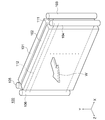
- FIG. 2 is a perspective view of the outdoor heat exchanger.
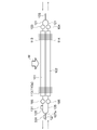
- FIG. 3 is a plan view for explaining the configuration of the outdoor heat exchanger. Note that fins (to be described later) are not shown in FIG. 2, and heat transfer tubes (to be described later) are not shown in FIG.
- the outdoor heat exchanger 100 includes a fan 100a, an upwind row 101 that is a first heat exchanger, and a downwind row 102 that is a second heat exchanger.
- the leeward row 102 is disposed further downwind than the leeward row 101 with respect to the airflow generated by the fan 100a. That is, the fan 100 a is disposed on the windward side of the windward row 101 and the leeward row 102, and the windward row 101 is disposed on the windward side of the leeward row 102.
- the air flow to the windward row 101 and the leeward row 102 is positively generated by the fan 100a.
- the outdoor heat exchanger 100 (the windward row 101, the leeward row 102, the fan 100a), the compressor 5, the expansion unit 7, the four-way valve 11, and the control unit 140 are accommodated in a case of the outdoor unit 17.
- the windward row 101 includes a windward heat transfer tube 111 that is a plurality of first heat transfer tubes, and a windward fin 113 that is a plurality of first fins that intersect the plurality of windward heat transfer tubes 111.
- the leeward row 102 includes a leeward heat transfer tube 112 that is a plurality of second heat transfer tubes and a leeward fin 114 that is a plurality of second fins that intersect the plurality of leeward heat transfer tubes 112.
- Each of the plurality of upwind heat transfer tubes 111 and the plurality of downwind heat transfer tubes 112 is a flat tube or a circular tube having a diameter of 4 mm or less.
- the windward row 101 and the leeward row 102 are arranged in a direction along the air flow W that performs heat exchange with the refrigerant, that is, the alignment direction Z.
- the windward row 101 is closer to the air intake surface 17 a of the case of the outdoor unit 17 than the leeward row 102.
- the leeward row 102 is closer to the air discharge surface 17 b provided in the case of the outdoor unit 17 than the windward row 101.
- the plurality of windward heat transfer tubes 111 are arranged in the vertical direction Y perpendicular to both the longitudinal direction, that is, the flow direction X in the heat transfer tube and the alignment direction Z.
- the plurality of leeward heat transfer tubes 112 are also arranged in the vertical direction Y perpendicular to both the longitudinal direction, that is, the heat transfer tube flow direction X and the alignment direction Z.
- the heat transfer tube flow direction X is orthogonal to both the alignment direction Z and the vertical direction Y.
- the plurality of windward fins 113 intersect with the plurality of windward heat transfer tubes 111 in plan view. More specifically, each of the plurality of upwind fins 113 extends in the alignment direction Z orthogonal to the flow direction X in the heat transfer tube.
- the plurality of leeward fins 114 intersect with the plurality of leeward heat transfer tubes 112 in plan view. More specifically, each of the plurality of leeward fins 114 extends in an alignment direction Z orthogonal to the flow direction X in the heat transfer tube.
- the inlet ends of the plurality of windward heat transfer tubes 111 are connected to a common windward inlet header 103, and the outlet ends of the plurality of windward heat transfer tubes 111 are connected to a common windward outlet header 105. Further, the inlet ends of the plurality of leeward heat transfer tubes 112 are connected to a common leeward inlet header 104, and the 112 outlet ends of the plurality of leeward heat transfer tubes are connected to a common leeward outlet header 106.
- the windward inlet header 103 and the leeward inlet header 104 are connected to a branching portion 123a of the inlet collecting pipe 123 via a plurality of (two in the first embodiment) inlet distribution pipes 121. Further, the windward outlet header 105 and the leeward outlet header 106 are connected to the branch portion 127a of the outlet collecting pipe 127 via a plurality of (two in the first embodiment) outlet distribution pipes 125. .
- the refrigeration cycle apparatus 1 further includes a first temperature sensor 131.
- the first temperature sensor 131 is arranged between the windward fin 113a closest to the branching portion 127a of the outlet collecting pipe 127 and the outlet collecting pipe 127.
- the windward outlet distribution pipe 125 is provided between the windward outlet header 105 and the branching portion 127a of the outlet collecting pipe 127. In other words, with respect to the direction in which the refrigerant flows during the cooling operation, it is provided at a position downstream of the windward outlet header 105 and upstream of the branching portion 127a of the outlet collecting pipe 127.
- the control unit 140 determines the end of the defrosting operation based on the temperature detected by the first temperature sensor 131.
- the heating operation will be described.
- the refrigerant flows as shown by dotted arrows in the figure.
- the high-temperature and high-pressure gas refrigerant sent from the compressor 5 passes through the four-way valve 11 and flows into the indoor heat exchanger 9.
- the refrigerant that has flowed into the indoor heat exchanger 9 is cooled by heat exchange with room air, and then flows into the expansion section 7 where the pressure is reduced.
- the decompressed low-temperature refrigerant flows into the outdoor heat exchanger 100.
- the refrigerant flowing into the outdoor heat exchanger 100 flows into the windward outlet header 105 and the leeward outlet header 106 through the outlet collecting pipe 127 and the branching portion 127a shown in FIG.
- the refrigerant that has flowed into the windward outlet header 105 and the leeward outlet header 106 flows separately into a plurality of windward heat transfer tubes 111 and a plurality of windward heat transfer tubes 112, respectively.
- coolant flows through the windward heat exchanger tube 111 and the leeward heat exchanger tube 112, it is heated and evaporated by the air sent out by the fan 100a.
- outdoor heat exchanger 100 in the first embodiment has a plurality of rows in a direction (alignment direction Z) substantially parallel to the flow of fluid (air) that exchanges heat with the refrigerant, and fluid that exchanges heat with the refrigerant.
- the outdoor heat exchanger 100 is a multi-row direct flow type heat exchanger.
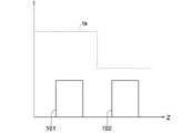
- FIG. 4 indicates the alignment direction Z shown in FIGS. 2 and 3, and the vertical axis indicates the temperature t.
- the temperature of the refrigerant flowing through the windward row 101 and the leeward row 102 is substantially the same. This is because the refrigerant flowing through the heat exchanger flows in a saturated state.
- the air temperature ta is cooled by heat exchange with the refrigerant when passing through the windward row 101, and the temperature decreases. Further, when the temperature of the fins or heat transfer tube surfaces of the heat exchanger is equal to or lower than the dew point temperature of air, dew is generated on the fin surfaces or heat transfer tube surfaces, and the humidity of the air is also reduced. Therefore, the temperature and humidity of the air flowing in the leeward row 102 are lower than the temperature and humidity of the air flowing in the leeward row 101.
- the upwind row 101 Since the magnitude of the heat exchange amount in the heat exchanger is determined by the difference between the refrigerant temperature and the air temperature or humidity, the upwind row 101 has a larger heat exchange amount than the downwind row 102.
- the temperature of the air when the temperature of the air is lowered, the temperature of the refrigerant is also lowered.
- the temperature of the fins or the heat transfer tubes is less than 0 degrees, water vapor in the air adheres to the heat exchanger as frost. Therefore, if no countermeasure is taken, more frost adheres to the upwind row 101 having a large amount of heat exchange, and the frost amount becomes uneven in the upwind row 101 and the downwind row 102.
- the defrosting operation is performed in the following manner.
- the four-way valve 11 in FIG. 3 is switched and a high-temperature and high-pressure refrigerant is caused to flow through the outdoor heat exchanger 100. That is, the refrigerant flow is in the opposite direction to that during heating operation.
- FIG. 5 shows the temperature of the refrigerant in the outdoor heat exchanger 100 during the defrosting operation.
- the horizontal axis in FIG. 5 indicates time S, and the vertical axis indicates the refrigerant temperature T. 5 indicates the temperature TA1 detected by the first temperature sensor 131 during the defrosting operation, and the dotted line in FIG. 5 indicates the outlet temperature TB of the leeward heat transfer tube 112 in the leeward row 102.
- the temperature of the outdoor heat exchanger 100 increases due to the supply of the high-temperature refrigerant, and the frost starts to melt at around 0 ° C. Due to the influence of latent heat for a while during the melting, The temperature stays at 0 degrees. When the frost melting is almost finished, the temperature rises again, and the defrosting operation is finished at the set defrosting finish temperature Tf.
- the temperature of the windward row 101 with a large amount of frost formation is less likely to rise than the temperature of the leeward row 102. Therefore, when the temperature of the leeward row 102 is sufficiently increased, for example, when the outlet temperature TB of the leeward row 102 exceeds the defrosting termination temperature Tf (time SB), the defrosting operation is finished. In this case, the temperature of the windward row 101 has not yet risen sufficiently, and frost in the windward row 101 may not be removed properly.
- the temperature TA1 detected by the first temperature sensor 131 disposed between the windward fin 113a closest to the branching portion 127a of the outlet collecting pipe 127 and the outlet collecting pipe 127 is defrosted.
- time SA time SA
- the defrosting operation is ended. In other words, the defrosting operation is continued until the temperature TA1 detected by the first temperature sensor 131 exceeds the defrosting end temperature Tf.
- the control unit 140 ends the defrosting operation based on the temperature detected by the first temperature sensor 131. Thereby, in both the upwind row 101 and the downwind row 102, it is possible to obtain a state in which frost is sufficiently melted.
- a second temperature sensor 231 is provided.
- the second temperature sensor 231 is disposed between the leeward fin 114 a closest to the branch portion 127 a of the outlet collecting pipe 127 and the outlet collecting pipe 127.
- the leeward side outlet distribution pipe 125 is provided between the leeward outlet header 106 and the branch portion 127a of the outlet collecting pipe 127.
- the second temperature sensor 231 is also connected to the control unit 140.
- the control unit 140 ends the defrosting operation. That is, the defrosting operation is ended when the temperature TA2> the defrosting end temperature Tf and the temperature TA1> the defrosting end temperature Tf are satisfied.
- FIG. 7 is a diagram of the same mode as that of FIG.
- this Embodiment 3 shall be the same as that of Embodiment 1 mentioned above except the part demonstrated below.
- a third temperature sensor 331 is provided.
- the third temperature sensor 331 is disposed in the outlet collecting pipe 127.
Landscapes
- Engineering & Computer Science (AREA)
- Physics & Mathematics (AREA)
- Mechanical Engineering (AREA)
- Thermal Sciences (AREA)
- General Engineering & Computer Science (AREA)
- Heat-Exchange Devices With Radiators And Conduit Assemblies (AREA)
- Other Air-Conditioning Systems (AREA)
Abstract
冷凍サイクル装置1は、圧縮機5と、室外熱交換器100と、膨張部7と、室内熱交換器9とを含む回路3を備えており、その室外熱交換器100は、ファン100aと、風上列101と、風下列102とを備えており、風上列101は、第1伝熱管111と、第1伝熱管111に交差する複数の第1フィン113とを備えており、複数の第1フィンと、集合管127の分岐部125との間に、第1温度センサ131が配置されている。
Description
本発明は、冷凍サイクル装置に関するものである。
冷凍サイクル装置を構成する熱交換器として、円形状の伝熱管を備えた熱交換器がある。しかし、熱交換器の高性能化を図る目的から、伝熱管の細径化が進み、近年では、扁平多穴管が伝熱管として使用されている熱交換器もある。
細径円管(たとえば直径4mmなど)もしくは扁平多穴管を伝熱管として使用した場合、細径円管もしくは扁平多穴管の流路断面積は、通常の円管の流路断面積よりも小さくなる。このため、通常の円管の伝熱管が用いられる態様と同等のパス数で熱交換器を構成した場合、伝熱管内の圧力損失が増大し、冷凍サイクルの運転効率が低下する。
圧力損失の低減は、熱交換器のパス数を増やすことや、1パスの伝熱管長さを短縮させることで、実現可能である。しかし、後者の場合、多列の熱交換器では、熱交換器を流れる冷媒を空気と対向して流すことができず、熱交換器効率が低下する。さらに、風上側の列と風下側の列との熱交換量に差が発生すため、特に、外気が低温条件では風上側の列に着霜が顕著に現れる。室外熱交換器に付着した霜は、定期的に除霜運転することで霜を溶かす必要がある。
除霜運転に関して、特開2008-224135号公報に開示された技術では、室外機の冷媒温度検出手段で検出された室外器冷媒温度と、外気温度検出手段で検出された外気温度との温度差から室外熱交換器への着霜量を判断して、着霜量が少ないと判定された場合には、霜取り禁止時間を長く設定している。
しかしながら、上述した特開2008-224135号公報に開示された技術においては、冷媒の分配の悪化により熱負荷に分布があるような熱交換器では、霜の付き方に偏りが発生し、多く霜が付いたところは霜の溶け残りが発生する。そして、残霜することで、除霜運転後の暖房運転時に能力の低下が生じることが懸念される。
本発明は、上記に鑑みてなされたものであり、熱負荷に分布があるような多列の熱交換器において残霜を低減することができる、冷凍サイクル装置を提供することを目的とする。
上述した目的を達成するため、本発明の冷凍サイクル装置は、圧縮機と、室外熱交換器と、膨張部と、室内熱交換器とを含む回路を備え、前記室外熱交換器は、ファンと、第1熱交換器と、前記ファンにより起こされる気流に対して前記第1熱交換器よりも風下に配置される第2熱交換器とを備えており、前記第1熱交換器は、第1伝熱管と、前記第1伝熱管に交差する複数の第1フィンとを備えており、前記第2熱交換器は、第2伝熱管を備えており、前記第1伝熱管は、第1ヘッダに接続されており、前記第2伝熱管は、第2ヘッダに接続されており、前記第1ヘッダと、前記第2ヘッダとは、分配管を介して、集合管の分岐部に接続されている、冷凍サイクル装置であって、前記複数の第1フィンと、前記集合管の分岐部との間に、第1温度センサを配置する。
本発明によれば、熱負荷に分布があるような多列の熱交換器において残霜を低減することができる。
以下、本発明の実施の形態について添付図面に基づいて説明する。なお、図中、同一符号は同一又は対応部分を示すものとする。
実施の形態1.
図1は、本実施の形態1の冷凍サイクル装置の構成を示す図である。冷凍サイクル装置1は、冷媒が循環する回路3を備えている。回路3は、少なくとも、圧縮機5と、室外熱交換器100と、膨張部7と、室内熱交換器9とを含んでいる。
図1は、本実施の形態1の冷凍サイクル装置の構成を示す図である。冷凍サイクル装置1は、冷媒が循環する回路3を備えている。回路3は、少なくとも、圧縮機5と、室外熱交換器100と、膨張部7と、室内熱交換器9とを含んでいる。
冷凍サイクル装置1は、暖房運転、および、冷房運転(除霜運転)の両方を行うことができ、回路3には、この運転の切り替えを行う四方弁11が設けられている。また、図1、図3、図6、図7においては、冷房運転(除霜運転)時の冷媒の流れが、実線矢印で示されており、暖房運転時の冷媒の流れが、点線矢印で示されている。
冷房運転時における冷媒の流れる向きを基準に回路3の構成要素を説明する。すなわち、本願明細書および本願請求の範囲では、冷房運転時における冷媒の流れる向きを基準に、入口および出口の文言を用いている。
まず、圧縮機5の出口は、四方弁11を介して、室外熱交換器100の入口につながっている。室外熱交換器100の出口は、膨張部7の入口につながっている。膨張部7は、例えば、膨張弁で構成されている。
膨張部7の出口は、室内熱交換器9の入口につながっている。室内熱交換器9の出口は、四方弁11を介して、圧縮機5の入口につながっている。
四方弁11には、制御部140が接続されており、後述するように、四方弁11の流路を切り替え、すなわち、暖房運転と冷房運転(除霜運転)との間の切り替えを行う。また、制御部140は、圧縮機5に接続されており、暖房運転、冷房運転および除霜運転のそれぞれにおいて、圧縮機5の動作を適切に制御する。
また、図中、矢印Wは、冷媒との熱交換を行う流体の流れを示している。具体的な例としては、矢印Wは、冷媒との熱交換を行う空気の流れを示している。
室内熱交換器9の風上側には、ファン9aが設けられている。このファン9aによって、室内熱交換器9に対する空気の流れが積極的に生み出されている。これら室内熱交換器9およびファン9aは、室内機15のケース内に収容されており、室内機15は、室内空間に配置されている。
図1~図3に基づき、室外熱交換器100の詳細について説明する。図2は、室外熱交換器の斜視図である。図3は、室外熱交換器の構成を説明するための平面図である。なお、図の明瞭性を優先し、図2には、後述するフィンが図示省略されており、図3には、後述する伝熱管が図示省略されている。
室外熱交換器100は、ファン100aと、第1熱交換器である風上列101と、第2熱交換器である風下列102とを備えている。風下列102は、ファン100aにより起こされる気流に対して風上列101よりも風下に配置されている。すなわち、ファン100aは、風上列101および風下列102よりも風上側に配置され、風上列101は、風下列102よりも風上側に配置されている。
このファン100aによって、風上列101および風下列102に対する空気の流れが積極的に生み出されている。室外熱交換器100(風上列101、風下列102、ファン100a)、圧縮機5、膨張部7、四方弁11、および、制御部140は、室外機17のケース内に収容されている。
風上列101は、複数の第1伝熱管である風上伝熱管111と、複数の風上伝熱管111に交差する複数の第1フィンである風上フィン113とを備えている。風下列102は、複数の第2伝熱管である風下伝熱管112と、複数の風下伝熱管112に交差する複数の第2フィンである風下フィン114とを備えている。複数の風上伝熱管111および複数の風下伝熱管112はそれぞれ、扁平管であるか、または、直径が4mm以下の円管である。
風上列101と、風下列102とは、冷媒との熱交換を行う空気の流れWに沿う方向すなわち整列方向Zに並んでいる。
風上列101は、風下列102よりも、室外機17のケースの空気取り入れ面17aに近い。別言すると、風下列102は、風上列101よりも、室外機17のケースに設けられた空気排出面17bに近い。
風上列101において、複数の風上伝熱管111は、長手方向すなわち伝熱管内流れ方向Xと、整列方向Zとの双方に直交する上下方向Yに並んでいる。同様に、風下列102において、複数の風下伝熱管112も、長手方向すなわち伝熱管内流れ方向Xと、整列方向Zとの双方に直交する上下方向Yに並んでいる。なお、伝熱管内流れ方向Xは、整列方向Zと、上下方向Yとの双方と直交している。
複数の風上フィン113は、平面視、複数の風上伝熱管111と交差している。より詳細には、複数の風上フィン113は、それぞれ、伝熱管内流れ方向Xに対して直交する整列方向Zに延びている。同様に、複数の風下フィン114は、平面視、複数の風下伝熱管112と交差している。より詳細には、複数の風下フィン114は、それぞれ、伝熱管内流れ方向Xに対して直交する整列方向Zに延びている。
複数の風上伝熱管111の入口端は、共通の風上入口ヘッダ103に接続されており、複数の風上伝熱管111の出口端は、共通の風上出口ヘッダ105に接続されている。また、複数の風下伝熱管112の入口端は、共通の風下入口ヘッダ104に接続されており、複数の風下伝熱管の112出口端は、共通の風下出口ヘッダ106に接続されている。
風上入口ヘッダ103と、風下入口ヘッダ104とは、複数の(本実施の形態1では2本の)入口分配管121を介して、入口集合管123の分岐部123aに接続されている。また、風上出口ヘッダ105と、風下出口ヘッダ106とは、複数の(本実施の形態1では2本の)出口分配管125を介して、出口集合管127の分岐部127aに接続されている。
冷凍サイクル装置1は、さらに、第1温度センサ131を備える。第1温度センサ131は、出口集合管127の分岐部127aに最も近い風上フィン113aと、出口集合管127との間に配置されている。具体的一例として、本実施の形態1では、風上出口ヘッダ105と、出口集合管127の分岐部127aとの間において、風上側の出口分配管125に設けられている。換言すれば、冷房運転時の冷媒の流れる向きに関して、風上出口ヘッダ105の下流部であって出口集合管127の分岐部127aの上流部となる位置に設けられている。制御部140は、この第1温度センサ131の検出温度に基づいて除霜運転の終了を決定する。
次に、上述した本実施の形態1の冷凍サイクル装置の動作について説明する。まず、暖房運転について説明する。暖房運転時は、図中、点線矢印で示したように冷媒が流れる。圧縮機5から送出された高温高圧のガス冷媒は、四方弁11を通過し、室内熱交換器9へ流入する。室内熱交換器9へ流入した冷媒は、室内空気との熱交換により冷却されたのち、膨張部7へ流入し、減圧される。減圧された低温の冷媒は、室外熱交換器100へ流入する。
室外熱交換器100へ流入した冷媒は、図3に示す出口集合管127、分岐部127aを経て、風上出口ヘッダ105および風下出口ヘッダ106に流入する。風上出口ヘッダ105および風下出口ヘッダ106に流入した冷媒は、それぞれ、複数の風上伝熱管111および複数の風下伝熱管112に分かれて流れる。そして、冷媒は、風上伝熱管111および風下伝熱管112を流れる間、ファン100aにより送出された空気により加熱されて蒸発する。
その後、蒸発した冷媒は、風上入口ヘッダ103および風下入口ヘッダ104で合流し、さらに、分岐部123aを経て、入口集合管123で合流する。室外熱交換器100を流出した冷媒は、四方弁11を通って、圧縮機5へ戻る。すなわち、本実施の形態1における室外熱交換器100は、冷媒と熱交換する流体(空気)の流れとほぼ平行な方向(整列方向Z)に複数の列を有し、冷媒と熱交換する流体(空気)の流れとほぼ直交する方向(伝熱管内流れ方向X)に関して、複数の列にわたって、全ての伝熱管内の冷媒の流れが同一方向に設定されている。つまり、室外熱交換器100は、多列直行流タイプの熱交換器である。
ここで、上記冷凍サイクルの動作において、室外熱交換器を通過する冷媒の温度と空気の温度との関係を、図4に示す。図4の横軸は、図2および図3に示す整列方向Zを示し、縦軸は温度tを示す。
図4に示されているように、風上列101と風下列102とを流れる冷媒の温度は概ね同じである。これは、熱交換器を流れる冷媒が飽和状態で流れているためである。
一方、空気温度taは、風上列101を通過する際に冷媒との熱交換により冷却され、温度が低下する。また、熱交換器のフィンもしくは伝熱管表面の温度が空気の露点温度以下となるとフィン表面もしくは伝熱管表面に露が発生し、空気の湿度も低下する。したがって、風下列102を流入する空気の温度及び湿度は、風上列101を流入する空気の温度及び湿度よりも低くなる。
熱交換器における熱交換量の大きさは、冷媒の温度と、空気の温度もしくは湿度との差で決まるため、風下列102よりも風上列101の方が熱交換量は多くなる。
さらに、空気の温度が低下すると、冷媒の温度も低下し、フィンもしくは伝熱管の温度が0度を下回る場合は空気中の水蒸気が霜として熱交換器に付着する。したがって、何らの対策もしない場合、霜は、熱交交換量の多い風上列101により多く付着し、風上列101と、風下列102とで霜量が不均一になる。
そこで、本実施の形態1では、次のような態様により除霜運転を行う。除霜運転では、図3における四方弁11を切替え、高温高圧の冷媒を、室外熱交換器100に流すことで実施する。すなわち、冷媒の流れは暖房運転時とは逆方向となる。
図5は、除霜運転中の室外熱交換器100の冷媒の温度を示す。図5の横軸は、時間Sを示し、縦軸は、冷媒温度Tを示す。また、図5における実線は、除霜運転時における、第1温度センサ131によって検出された温度TA1であり、図5における点線は、風下列102の風下伝熱管112の出口温度TBを示す。
除霜運転を開始(時間SSの時点)すると、高温冷媒の供給により、室外熱交換器100の温度は上昇し、0度付近で、霜の融解が始まり、融解中しばらくは潜熱の影響により、温度は0度に止まる。そして、霜の融解がほぼ終了すると、再び、温度上昇が生じ、設定された霜取終了温度Tfにおいて、除霜運転を終了する。
しかしながら、ここで、着霜量が多い風上列101の温度は、風下列102の温度よりも上昇がしにくい。よって、風下列102の温度が十分に上昇した時、例えば、風下列102の出口温度TBが霜取終了温度Tfを超えた時(時間SBの時点)に、除霜運転を終了してしまった場合、風上列101の温度は未だ十分に上昇してなく、風上列101における霜が適切に除去しきれていない恐れがある。
そこで、本実施の形態1では、出口集合管127の分岐部127aに最も近い風上フィン113aと、出口集合管127との間に配置した第1温度センサ131により検出された温度TA1が霜取終了温度Tfを超えた時(時間SAの時点)に、除霜運転を終了する。換言すると、第1温度センサ131により検出された温度TA1が霜取終了温度Tfを超えるまでは、除霜運転を継続する。このように、本実施の形態1では、制御部140は、第1温度センサ131の検出温度に基づいて除霜運転を終了する。これにより、風上列101および風下列102の双方において、霜が十分に溶けた状態を得ることができる。
なお、霜取終了温度Tfは、室外熱交換器の構成条件や使用環境条件に応じて個別に適切に設定するのが好適であり、0度より大きく20度よりも小さい温度範囲の中から設定することができるが、好ましくは、5度より大きく20度よりも小さい温度範囲の中から設定するとよい。
以上に説明した本実施の形態1の冷凍サイクル装置によれば、熱負荷に分布があるような多列の熱交換器において残霜を低減することができる。
実施の形態2.
次に、図6に基づいて、本発明の実施の形態2について説明する。図6は、本実施の形態2についての、図3と同態様の図である。なお、本実施の形態2は、以下に説明する部分を除いては、上述した実施の形態1と同様であるものとする。
次に、図6に基づいて、本発明の実施の形態2について説明する。図6は、本実施の形態2についての、図3と同態様の図である。なお、本実施の形態2は、以下に説明する部分を除いては、上述した実施の形態1と同様であるものとする。
本実施の形態2では、第2温度センサ231が設けられている。第2温度センサ231は、出口集合管127の分岐部127aに最も近い風下フィン114aと、出口集合管127との間に配置されている。具体的一例としては、風下出口ヘッダ106と、出口集合管127の分岐部127aとの間において、風下側の出口分配管125に設けられている。第2温度センサ231もまた、制御部140に接続されている。
本実施の形態2では、除霜運転時、第2温度センサ231により検出された温度TA2(なお、温度TA2は、上述した温度TBと同じである)と、第1温度センサ131により検出された温度TA1との双方が、設定した霜取終了温度Tfを超えた時に、制御部140は、除霜運転を終了する。つまり、温度TA2>霜取終了温度Tf、且つ、温度TA1>霜取終了温度Tfが満たされたときに、除霜運転が終了される。
以上に説明した本実施の形態2の冷凍サイクル装置によっても、熱負荷に分布があるような多列の熱交換器において残霜を低減することができ、風下側の冷媒温度も検出することで、より確実に熱交換器の霜を溶かすことができる。
実施の形態3.
次に、図7に基づいて、本発明の実施の形態2について説明する。図7は、本実施の形態3についての、図3と同態様の図である。なお、本実施の形態3は、以下に説明する部分を除いては、上述した実施の形態1と同様であるものとする。
次に、図7に基づいて、本発明の実施の形態2について説明する。図7は、本実施の形態3についての、図3と同態様の図である。なお、本実施の形態3は、以下に説明する部分を除いては、上述した実施の形態1と同様であるものとする。
本実施の形態3では、第3温度センサ331が設けられている。第3温度センサ331は、出口集合管127に配置されている。
以上に説明した本実施の形態3の冷凍サイクル装置によっても、熱負荷に分布があるような多列の熱交換器において残霜を低減することができる。また、冷房運転時、出口分配管125の合流部で温度を検出できるため、冷凍サイクルにおいて適切な過冷却制御を行うことができる。
以上、好ましい実施の形態を参照して本発明の内容を具体的に説明したが、本発明の基本的技術思想及び教示に基づいて、当業者であれば、種々の改変態様を採り得ることは自明である。
上述した実施の形態では、空気調和機である冷凍サイクル装置として説明してきたが、本発明は、これに限定されるものではなく、圧縮機、膨張部、室内熱交換器、室外熱交換器を含む冷凍回路を備えた冷凍サイクル装置に広く適用することができる。よって、例えば、本発明は、給湯器である冷凍サイクル装置として実施することも可能である。
また、上述した実施の形態においては、室外熱交換器は2列の熱交換器として説明しているが、本発明は、これに限定されるものではなく、3列以上の熱交換器に適用することも可能である。その場合、本発明は、上記の風上列が、3列以上の熱交換器における最も風上側の列であるものとして、実施される。
第1温度センサは、出口集合管の分岐部に最も近い風上フィンと、出口集合管との間に配置されていればよく、上述した実施の形態は、その一例である。よって、他の例として、第1温度センサは、風上出口ヘッダに取り付けられていてもよい。あるいは、第1温度センサは、出口集合管の分岐部に最も近い風上フィンと、風上出口ヘッダとの間で、風上伝熱管に取り付けられていてもよい。また、その場合、第1温度センサは、より下に位置する風上伝熱管に取り付けられている方が好ましく、最も下に位置する風上伝熱管に取り付けられていると最適である。
1 冷凍サイクル装置、3 回路、5 圧縮機、7 膨張部、9 室内熱交換器、100 室外熱交換器、100a ファン、101 風上列、102 風下列、103 風上入口ヘッダ、104 風下入口ヘッダ、105 風上出口ヘッダ、106 風下出口ヘッダ、111 風上伝熱管、112 風下伝熱管、113 風上フィン、114 風下フィン、121 入口分配管、123 入口集合管、123a、127a 分岐部、125 出口分配管、127 出口集合管、131 第1温度センサ、231 第2温度センサ、331 第3温度センサ。
Claims (6)
- 圧縮機と、室外熱交換器と、膨張部と、室内熱交換器とを含む回路を備え、
前記室外熱交換器は、ファンと、第1熱交換器と、前記ファンにより起こされる気流に対して前記第1熱交換器よりも風下に配置される第2熱交換器とを備えており、
前記第1熱交換器は、第1伝熱管と、前記第1伝熱管に交差する複数の第1フィンとを備えており、
前記第2熱交換器は、第2伝熱管を備えており、
前記第1伝熱管は、第1ヘッダに接続されており、
前記第2伝熱管は、第2ヘッダに接続されており、
前記第1ヘッダと、前記第2ヘッダとは、分配管を介して、集合管の分岐部に接続されている、冷凍サイクル装置であって、
前記複数の第1フィンと、前記集合管の分岐部との間に、第1温度センサを配置した、
冷凍サイクル装置。 - 前記冷凍サイクル装置は、制御部とを備え、
前記制御部は、前記第1温度センサと接続され、前記第1温度センサの検出温度に基づいて除霜運転の終了を決定する、
請求項1の冷凍サイクル装置。 - 前記第1温度センサは、前記第1ヘッダと前記集合管の分岐部との間において、前記分配管に設けられている、
請求項1または2の冷凍サイクル装置。 - 前記冷凍サイクル装置は、前記第2伝熱管に交差する複数の第2フィンと、第2温度センサとを備え、
前記第2温度センサは、前記集合管の分岐部に最も近い前記複数の第2フィンと、前記集合管の分岐部との間に、配置されている、
請求項1~3の冷凍サイクル装置。 - 前記冷凍サイクル装置は、第3温度センサを備え、
前記第3温度センサは、前記集合管に配置されている、
請求項1~3の冷凍サイクル装置。 - 前記第1伝熱管および前記第2伝熱管はそれぞれ、扁平管であるか、または、直径が4mm以下の円管である、
請求項1~5の何れか一項の冷凍サイクル装置。
Priority Applications (3)
| Application Number | Priority Date | Filing Date | Title |
|---|---|---|---|
| PCT/JP2015/052689 WO2016121103A1 (ja) | 2015-01-30 | 2015-01-30 | 冷凍サイクル装置 |
| EP15880000.3A EP3252400A4 (en) | 2015-01-30 | 2015-01-30 | Refrigeration cycle device |
| JP2016571640A JPWO2016121103A1 (ja) | 2015-01-30 | 2015-01-30 | 冷凍サイクル装置 |
Applications Claiming Priority (1)
| Application Number | Priority Date | Filing Date | Title |
|---|---|---|---|
| PCT/JP2015/052689 WO2016121103A1 (ja) | 2015-01-30 | 2015-01-30 | 冷凍サイクル装置 |
Publications (1)
| Publication Number | Publication Date |
|---|---|
| WO2016121103A1 true WO2016121103A1 (ja) | 2016-08-04 |
Family
ID=56542753
Family Applications (1)
| Application Number | Title | Priority Date | Filing Date |
|---|---|---|---|
| PCT/JP2015/052689 Ceased WO2016121103A1 (ja) | 2015-01-30 | 2015-01-30 | 冷凍サイクル装置 |
Country Status (3)
| Country | Link |
|---|---|
| EP (1) | EP3252400A4 (ja) |
| JP (1) | JPWO2016121103A1 (ja) |
| WO (1) | WO2016121103A1 (ja) |
Cited By (1)
| Publication number | Priority date | Publication date | Assignee | Title |
|---|---|---|---|---|
| CN106322847A (zh) * | 2016-10-17 | 2017-01-11 | 珠海格力电器股份有限公司 | 多排换热器和包括该多排换热器的空调器 |
Citations (6)
| Publication number | Priority date | Publication date | Assignee | Title |
|---|---|---|---|---|
| JPS6214281U (ja) * | 1985-07-12 | 1987-01-28 | ||
| JPS6250467U (ja) * | 1985-09-17 | 1987-03-28 | ||
| JPS6369963U (ja) * | 1986-10-22 | 1988-05-11 | ||
| JP2005226866A (ja) * | 2004-02-10 | 2005-08-25 | Denso Corp | 冷凍サイクル装置 |
| JP2006284134A (ja) * | 2005-04-04 | 2006-10-19 | Matsushita Electric Ind Co Ltd | 熱交換器 |
| JP2014066420A (ja) * | 2012-09-26 | 2014-04-17 | Hitachi Appliances Inc | 冷凍装置 |
Family Cites Families (13)
| Publication number | Priority date | Publication date | Assignee | Title |
|---|---|---|---|---|
| JPS6317369A (ja) * | 1986-07-08 | 1988-01-25 | 松下精工株式会社 | 空気調和機 |
| JPS6349673A (ja) * | 1986-08-19 | 1988-03-02 | 松下精工株式会社 | 空気調和機 |
| JPS6467577A (en) * | 1987-09-08 | 1989-03-14 | Toshiba Corp | Multiple type heat pump type air conditioner |
| DE3938842A1 (de) * | 1989-06-06 | 1991-05-29 | Thermal Waerme Kaelte Klima | Verfluessiger fuer ein kaeltemittel einer fahrzeugklimaanlage |
| JPH03199857A (ja) * | 1989-12-27 | 1991-08-30 | Toshiba Corp | 空気調和機 |
| JP3004676B2 (ja) * | 1990-04-20 | 2000-01-31 | 株式会社日立製作所 | 冷凍サイクル装置 |
| JPH04110576A (ja) * | 1990-08-31 | 1992-04-13 | Toshiba Corp | ヒートポンプ式空気調和装置 |
| JPH0861799A (ja) * | 1994-08-26 | 1996-03-08 | Sharp Corp | 空気調和機 |
| JP3086181B2 (ja) * | 1996-10-16 | 2000-09-11 | ホシザキ電機株式会社 | 冷却貯蔵庫 |
| JP2003185307A (ja) * | 2001-12-20 | 2003-07-03 | Fujitsu General Ltd | 空気調和機の制御装置 |
| JP2006322691A (ja) * | 2005-05-20 | 2006-11-30 | Denso Corp | エジェクタサイクル |
| JP4874223B2 (ja) * | 2007-12-25 | 2012-02-15 | 三菱電機株式会社 | 空気調和機 |
| KR101572845B1 (ko) * | 2009-08-19 | 2015-11-30 | 엘지전자 주식회사 | 공기조화기 |
-
2015
- 2015-01-30 WO PCT/JP2015/052689 patent/WO2016121103A1/ja not_active Ceased
- 2015-01-30 JP JP2016571640A patent/JPWO2016121103A1/ja active Pending
- 2015-01-30 EP EP15880000.3A patent/EP3252400A4/en not_active Withdrawn
Patent Citations (6)
| Publication number | Priority date | Publication date | Assignee | Title |
|---|---|---|---|---|
| JPS6214281U (ja) * | 1985-07-12 | 1987-01-28 | ||
| JPS6250467U (ja) * | 1985-09-17 | 1987-03-28 | ||
| JPS6369963U (ja) * | 1986-10-22 | 1988-05-11 | ||
| JP2005226866A (ja) * | 2004-02-10 | 2005-08-25 | Denso Corp | 冷凍サイクル装置 |
| JP2006284134A (ja) * | 2005-04-04 | 2006-10-19 | Matsushita Electric Ind Co Ltd | 熱交換器 |
| JP2014066420A (ja) * | 2012-09-26 | 2014-04-17 | Hitachi Appliances Inc | 冷凍装置 |
Non-Patent Citations (1)
| Title |
|---|
| See also references of EP3252400A4 * |
Cited By (1)
| Publication number | Priority date | Publication date | Assignee | Title |
|---|---|---|---|---|
| CN106322847A (zh) * | 2016-10-17 | 2017-01-11 | 珠海格力电器股份有限公司 | 多排换热器和包括该多排换热器的空调器 |
Also Published As
| Publication number | Publication date |
|---|---|
| JPWO2016121103A1 (ja) | 2017-04-27 |
| EP3252400A4 (en) | 2018-10-10 |
| EP3252400A1 (en) | 2017-12-06 |
Similar Documents
| Publication | Publication Date | Title |
|---|---|---|
| US10054376B2 (en) | Heat exchanger and air-conditioning apparatus | |
| JP6333401B2 (ja) | 熱交換器、及び、空気調和装置 | |
| JP6336100B2 (ja) | 熱交換器、及び、空気調和装置 | |
| JP6388670B2 (ja) | 冷凍サイクル装置 | |
| EP4279850A3 (en) | Outdoor unit of air-conditioning apparatus and air-conditioning apparatus | |
| EP3156752B1 (en) | Heat exchanger | |
| US10101091B2 (en) | Heat exchanger and refrigeration cycle apparatus using the same heat exchanger | |
| JPWO2018078800A1 (ja) | 熱交換器及び冷凍サイクル装置 | |
| US10914499B2 (en) | Outdoor unit and refrigeration cycle apparatus including the same | |
| JP5627635B2 (ja) | 空気調和機 | |
| JP6611101B2 (ja) | 冷凍サイクル装置 | |
| CN108224602A (zh) | 用于空调室外换热器的分歧管和空调器 | |
| WO2016121103A1 (ja) | 冷凍サイクル装置 | |
| JP7414845B2 (ja) | 冷凍サイクル装置 | |
| JP5677237B2 (ja) | 空気調和機 | |
| JP2011145011A (ja) | 空気調和機 | |
| KR101172572B1 (ko) | 분배기 및 이를 포함하는 공기 조화기 | |
| WO2019130394A1 (ja) | 熱交換器および冷凍サイクル装置 | |
| JP5864030B1 (ja) | 熱交換器、及び、この熱交換器を備えた冷凍サイクル装置 | |
| CN117355721A (zh) | 热交换器、具备热交换器的空调装置的室外机、以及具备空调装置的室外机的空调装置 | |
| CN207936345U (zh) | 用于空调室外换热器的分歧管和空调器 | |
| JP6910436B2 (ja) | 室外ユニットおよび冷凍サイクル装置 | |
| WO2011111602A1 (ja) | 空気調和機 | |
| CN204612278U (zh) | 空调系统 | |
| CN101482345B (zh) | 一种高效空调换热器 |
Legal Events
| Date | Code | Title | Description |
|---|---|---|---|
| 121 | Ep: the epo has been informed by wipo that ep was designated in this application |
Ref document number: 15880000 Country of ref document: EP Kind code of ref document: A1 |
|
| ENP | Entry into the national phase |
Ref document number: 2016571640 Country of ref document: JP Kind code of ref document: A |
|
| REEP | Request for entry into the european phase |
Ref document number: 2015880000 Country of ref document: EP |
|
| NENP | Non-entry into the national phase |
Ref country code: DE |