WO2016121251A1 - 装置及び方法 - Google Patents
装置及び方法 Download PDFInfo
- Publication number
- WO2016121251A1 WO2016121251A1 PCT/JP2015/084945 JP2015084945W WO2016121251A1 WO 2016121251 A1 WO2016121251 A1 WO 2016121251A1 JP 2015084945 W JP2015084945 W JP 2015084945W WO 2016121251 A1 WO2016121251 A1 WO 2016121251A1
- Authority
- WO
- WIPO (PCT)
- Prior art keywords
- base station
- directional beam
- information
- interference
- signal
- Prior art date
- Legal status (The legal status is an assumption and is not a legal conclusion. Google has not performed a legal analysis and makes no representation as to the accuracy of the status listed.)
- Ceased
Links
Images







Classifications
-
- H—ELECTRICITY
- H04—ELECTRIC COMMUNICATION TECHNIQUE
- H04L—TRANSMISSION OF DIGITAL INFORMATION, e.g. TELEGRAPHIC COMMUNICATION
- H04L5/00—Arrangements affording multiple use of the transmission path
- H04L5/003—Arrangements for allocating sub-channels of the transmission path
- H04L5/0058—Allocation criteria
- H04L5/0073—Allocation arrangements that take into account other cell interferences
-
- H—ELECTRICITY
- H04—ELECTRIC COMMUNICATION TECHNIQUE
- H04B—TRANSMISSION
- H04B7/00—Radio transmission systems, i.e. using radiation field
- H04B7/02—Diversity systems; Multi-antenna system, i.e. transmission or reception using multiple antennas
- H04B7/022—Site diversity; Macro-diversity
- H04B7/024—Co-operative use of antennas of several sites, e.g. in co-ordinated multipoint or co-operative multiple-input multiple-output [MIMO] systems
-
- H—ELECTRICITY
- H04—ELECTRIC COMMUNICATION TECHNIQUE
- H04L—TRANSMISSION OF DIGITAL INFORMATION, e.g. TELEGRAPHIC COMMUNICATION
- H04L5/00—Arrangements affording multiple use of the transmission path
- H04L5/003—Arrangements for allocating sub-channels of the transmission path
- H04L5/0032—Distributed allocation, i.e. involving a plurality of allocating devices, each making partial allocation
-
- H—ELECTRICITY
- H04—ELECTRIC COMMUNICATION TECHNIQUE
- H04W—WIRELESS COMMUNICATION NETWORKS
- H04W16/00—Network planning, e.g. coverage or traffic planning tools; Network deployment, e.g. resource partitioning or cells structures
- H04W16/24—Cell structures
- H04W16/28—Cell structures using beam steering
-
- H—ELECTRICITY
- H04—ELECTRIC COMMUNICATION TECHNIQUE
- H04W—WIRELESS COMMUNICATION NETWORKS
- H04W24/00—Supervisory, monitoring or testing arrangements
- H04W24/10—Scheduling measurement reports ; Arrangements for measurement reports
-
- H—ELECTRICITY
- H04—ELECTRIC COMMUNICATION TECHNIQUE
- H04W—WIRELESS COMMUNICATION NETWORKS
- H04W72/00—Local resource management
- H04W72/04—Wireless resource allocation
-
- H—ELECTRICITY
- H04—ELECTRIC COMMUNICATION TECHNIQUE
- H04W—WIRELESS COMMUNICATION NETWORKS
- H04W72/00—Local resource management
- H04W72/04—Wireless resource allocation
- H04W72/044—Wireless resource allocation based on the type of the allocated resource
- H04W72/0446—Resources in time domain, e.g. slots or frames
-
- H—ELECTRICITY
- H04—ELECTRIC COMMUNICATION TECHNIQUE
- H04B—TRANSMISSION
- H04B7/00—Radio transmission systems, i.e. using radiation field
- H04B7/02—Diversity systems; Multi-antenna system, i.e. transmission or reception using multiple antennas
- H04B7/04—Diversity systems; Multi-antenna system, i.e. transmission or reception using multiple antennas using two or more spaced independent antennas
- H04B7/0413—MIMO systems
- H04B7/0452—Multi-user MIMO systems
-
- H—ELECTRICITY
- H04—ELECTRIC COMMUNICATION TECHNIQUE
- H04W—WIRELESS COMMUNICATION NETWORKS
- H04W72/00—Local resource management
- H04W72/50—Allocation or scheduling criteria for wireless resources
- H04W72/54—Allocation or scheduling criteria for wireless resources based on quality criteria
- H04W72/541—Allocation or scheduling criteria for wireless resources based on quality criteria using the level of interference
Definitions
- the present disclosure relates to an apparatus and a method.
- the base station performs beam forming using a directional antenna including a large number of antenna elements (for example, about 100 antenna elements).
- a technique is a form of a technique called large-scale MIMO or massive MIMO.
- the half width of the beam becomes narrow. That is, a sharp beam is formed.
- by arranging the multiple antenna elements on a plane it is possible to form a beam in a desired three-dimensional direction.
- Patent Documents 1 to 3 disclose techniques applied when a directional beam in a three-dimensional direction is used.
- a directional beam formed by the base station can reach a neighboring cell.
- a large-scale MIMO directional beam can reach neighboring cells and result in high received power. As a result, large interference can occur.
- an apparatus comprising: an acquisition unit that acquires the information provided by a neighboring base station; and a control unit that determines an operation of the base station related to signal transmission by the directional beam based on the information.
- information on a directional beam that is an interference source for a terminal device connected to a base station in the vicinity of the base station among a plurality of directional beams that can be formed by the base station by a processor.
- a method comprising: obtaining the information provided by the neighboring base station; and determining an operation of the base station regarding transmission of a signal by the directional beam based on the information.
- a calculation unit that calculates an interference amount from a reference signal for channel quality measurement transmitted by a neighboring base station of a serving base station, and interference among radio resources to which the reference signal is transmitted
- An apparatus includes a detection unit that detects a radio resource with a small amount and a report unit that reports the radio resource with a small amount of interference to a base station.
- the present disclosure it is possible to further reduce interference of directional beams between cells.
- the above effects are not necessarily limited, and any of the effects shown in the present specification or other effects that can be grasped from the present specification are exhibited together with or in place of the above effects. May be.
- FIG. 2 is an explanatory diagram illustrating an example of a schematic configuration of a system according to an embodiment of the present disclosure.
- FIG. An example of the configuration of the base station according to the embodiment will be described. It is a block diagram which shows an example of a structure of the terminal device which concerns on the same embodiment.
- FIG. 6 is a sequence diagram showing a first example of a schematic flow of processing according to the embodiment.
- FIG. 10 is a sequence diagram illustrating a second example of a schematic flow of a process according to the embodiment.
- FIG. 10 is a sequence diagram illustrating a third example of a schematic flow of a process according to the embodiment.
- It is a block diagram which shows the 1st example of schematic structure of eNB. It is a block diagram which shows the 2nd example of schematic structure of eNB.
- It is a block diagram which shows an example of a schematic structure of a smart phone. It is a block diagram which shows an example of a schematic structure of a car navigation apparatus.
- elements having substantially the same functional configuration may be distinguished by adding different alphabets after the same reference numerals.
- a plurality of elements having substantially the same functional configuration are differentiated as necessary, such as the terminal devices 200A, 200B, and 200C.
- the terminal devices 200A, 200B, and 200C are simply referred to as the terminal device 200 when it is not necessary to distinguish between them.
- Beam forming (a) Necessity of large-scale MIMO
- 3GPP is examining various technologies for improving the capacity of a cellular system in order to accommodate explosively increasing traffic. It is said that a capacity about 1000 times the current capacity will be required in the future.
- technologies such as MU-MIMO and CoMP, the capacity of the cellular system is considered to increase only about several times. Therefore, an innovative method is required.
- 8-layer MIMO can be realized in the case of SU-MIMO (Single-User Multi-Input Multiple-Input Multiple-Output).
- 8-layer MIMO is a technique for spatially multiplexing eight independent streams.
- two layers of MU-MIMO can be realized for four users.
- UE User Equipment
- the base station performs beam forming using a directional antenna including a large number of antenna elements (for example, about 100 antenna elements).
- a technique is one form of a technique called large-scale MIMO or massive MIMO.
- the half width of the beam becomes narrow. That is, a sharp beam is formed.
- by arranging the multiple antenna elements on a plane it is possible to form a beam in a desired three-dimensional direction. For example, it has been proposed to transmit a signal to a terminal device existing at the position by forming a beam directed to a position higher than the base station (for example, an upper floor of a high-rise building).
- the typical beam forming In typical beam forming, it is possible to change the beam direction in the horizontal direction. Therefore, it can be said that the typical beam forming is two-dimensional beam forming.
- the beam direction can be changed in the vertical direction in addition to the horizontal direction. Therefore, it can be said that large-scale MIMO beamforming is three-dimensional beamforming.
- MU-MIMO since the number of antennas increases, the number of users in MU-MIMO can be increased.
- Such a technique is another form of a technique called large scale MIMO or massive MIMO.
- the number of antennas of the UE is two, the number of spatially independent streams for one UE is two, and therefore, MU-MIMO rather than increasing the number of streams for one UE. It is more reasonable to increase the number of users.
- Weight set A weight set for beam forming (that is, a set of weight coefficients for a plurality of antenna elements) is expressed as a complex number.
- a weight set for beam forming of large scale MIMO will be described with reference to FIG.
- FIG. 1 is an explanatory diagram for describing a weight set for large-scale MIMO beamforming.
- antenna elements arranged in a lattice shape are shown. Also shown are two axes x, y orthogonal to the plane on which the antenna element is arranged, and one axis z orthogonal to the plane.
- the direction of the beam to be formed is represented by, for example, an angle phi (Greek letter) and an angle theta (Greek letter).
- the angle phi (Greek letter) is an angle formed between the x-axis component and the xy plane component in the beam direction.
- the angle theta (Greek letter) is an angle formed by the beam direction and the z axis.
- the weighting factor V m, n of the antenna element arranged m-th in the x-axis direction and n-th arranged in the y-axis direction can be expressed as follows.
- f is the frequency and c is the speed of light.
- J is an imaginary unit in a complex number.
- D x is the distance between the antenna elements in the x-axis direction, and dy is the distance between the antenna elements in the y-axis direction.
- the coordinates of the antenna element are expressed as follows.
- a weight set for typical beam forming includes a weight set for obtaining directivity in the horizontal direction and a weight set for phase adjustment of dual layer MIMO (that is, 2 corresponding to different polarizations). And a weight set for phase adjustment between two antenna sub-arrays).
- the large-scale MIMO beamforming (three-dimensional beamforming) weight set includes a first weight set for obtaining directivity in the horizontal direction and a second weight set for obtaining directivity in the vertical direction. And a third weight set for phase adjustment of dual layer MIMO.
- FIG. 2 is an explanatory diagram for explaining an example of a case where large-scale MIMO beamforming is performed.
- a base station 71 and a high-rise building 73 are shown.
- the base station 71 forms a directional beam 79 to the high-rise building 73 in addition to the directional beams 75 and 77 to the ground.
- the measurement includes measurement for selecting a cell and measurement for feeding back CQI (Channel Quality Indicator) and the like after connection. The latter measurement is required to be performed in a shorter time.
- CQI Channel Quality Indicator
- the measurement of the amount of interference from neighboring cells is also considered to be a kind of CQI measurement.
- CQI measurement CRS Cell-specific Reference Signal
- CSI-RS Channel State Information Reference Signal
- CSI-RS is transmitted without beamforming, similar to CRS. That is, the CSI-RS is transmitted without being multiplied by a weight set for beamforming, as in the case of CRS.
- a weight set for beamforming as in the case of CRS.
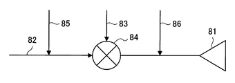
- FIG. 3 is an explanatory diagram for explaining the relationship between weighting coefficient multiplication and reference signal insertion.
- the transmission signal 82 corresponding to each antenna element 81 is complex-multiplied by a weight coefficient 83 in a multiplier 84. Then, a transmission signal 82 obtained by complex multiplication of the weighting coefficient 83 is transmitted from the antenna element 81.
- the DR-MS 85 is inserted before the multiplier 84, and the multiplier 84 multiplies the weight coefficient 83 by a complex multiplication. Then, the DR-MS 85 obtained by complex multiplication of the weight coefficient 83 is transmitted from the antenna element 81.
- the CSI-RS 86 (and CRS) is inserted after the multiplier 84. The CSI-RS 86 (and CRS) is transmitted from the antenna element 81 without being multiplied by the weighting coefficient 83.
- CSI-RS is transmitted without beamforming
- pure channel H or channel response H that is not affected by beamforming is used.
- This channel H is used to feed back RI (Rank Indicator), PMI (Precoding Matrix Indicator), and CQI (Channel Quality Indicator). Note that only CQI is fed back depending on the transmission mode. Also, the amount of interference can be fed back.
- the transmission frequency of CRS is higher than the transmission frequency of CSI-RS. That is, the CSI-RS cycle is longer than the CRS cycle.
- a first approach for transmitting CSI-RS without beamforming and a second approach for transmitting CSI-RS with beamforming ie, transmitting CSI-RS with a directional beam
- the first approach is a conventional approach
- the second approach is a new approach.
- FIG. 4 the relationship between weight coefficient multiplication and reference signal insertion in the new approach (second approach) will be described.
- FIG. 4 is an explanatory diagram for explaining the relationship between weighting factor multiplication and reference signal insertion in a new approach.
- transmission signal 92 corresponding to each antenna element 91 is complex-multiplied by weighting factor 93 in multiplier 94.
- a transmission signal 92 obtained by complex multiplication of the weight coefficient 93 is transmitted from the antenna element 91.
- the DR-MS 95 is inserted in front of the multiplier 94, and the multiplier 94 multiplies the weight coefficient 93 in a complex manner.
- the DR-MS 95 obtained by complex multiplication of the weight coefficient 93 is transmitted from the antenna element 91.
- CSI-RS 96 is inserted before multiplier 94, and weighting factor 93 is complex-multiplied by multiplier 94. Then, CSI-RS 96 obtained by complex multiplication of the weight coefficient 93 is transmitted from the antenna element 91.
- the CRS 97 (and normal CSI-RS) is inserted after the multiplier 94. The CRS 97 (and normal CSI-RS) is transmitted from the antenna element 91 without being multiplied by the weight coefficient 93.
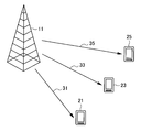
- FIG. 5 is an explanatory diagram for explaining an example of an environment where a directional beam is not reflected.
- the eNB 11 and the UEs 21, 23, and 25 are shown.
- the eNB 11 forms a directional beam 31 directed to the UE 21, a directional beam 33 directed to the UE 23, and a directional beam 35 directed to the UE 25.
- the directional beams 31, 33 and 35 are not reflected, and no interference occurs between the directional beams 31, 33 and 35.
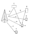
- FIG. 6 is an explanatory diagram for explaining an example of an environment in which a directional beam is reflected.
- the eNB 11 and the UEs 21, 23, and 25 are shown.
- obstacles 41 and 43 are shown.
- the obstacles 41 and 43 are buildings.
- the eNB 11 forms a directional beam 31 directed to the UE 21, a directional beam 33 directed to the UE 23, and a directional beam 35 directed to the UE 25.
- the directional beam 35 is reflected by the obstacles 41 and 43 and reaches the UE 23. For this reason, interference occurs between the directional beam 33 and the directional beam 35.
- FIG. 7 is an explanatory diagram for explaining an example of interference between directional beams of different cells.
- eNBs 11 and 13 and UEs 21, 23, and 25 are shown.
- the eNB 11 forms a directional beam 31 directed to the UE 21, a directional beam 33 directed to the UE 23, and a directional beam 35 directed to the UE 25.
- the eNB 13 forms a directional beam 37, and the directional beam 37 reaches the UE 25. Therefore, interference occurs between the directional beam 35 formed by the eNB 11 and the directional beam 37 formed by the eNB 13.
- Interference may occur between two directional beams, or interference may occur between three or more directional beams.
- the number of directional beams in which interference occurs depends on the UE. For example, referring again to FIG. 6, interference is not generated in each of the UEs 21 and 25, but interference is generated between the three directional beams in the UE 23. That is, the state of interference differs depending on the location.
- a single operating band has a high frequency band (component carrier) and a low frequency band (component carrier), but the interference situation is generally the same in each frequency band. I can say that.
- the eNB In order to suppress such interference, it is important that the eNB first grasps the state of directional beam interference. Since the eNB cannot know the situation of such directional beam interference itself, it is conceivable that the UE reports the situation of directional beam interference to the eNB. For example, it is conceivable to calculate the interference amount of a directional beam other than the desired directional beam from the CSI-RS. It is also conceivable to use a CSI feedback procedure.
- RRM Radio Resource Management
- RSRP Reference Signal Received Power
- RSRQ Reference Signal Received Quality
- RI, CQI, PMI, etc. included in CSI It is a measurement to determine.
- the former is mainly performed for cell selection and is performed by both the RRC idle mode UE and the RRC connected mode UE.
- the latter is performed in order to know the interference situation and is performed by the UE in the RRC connection mode.
- CSI-RS CSI-RS is defined in Release 10.
- a normal CSI-RS is also called a non zero power CSI-RS. Since the purpose of CSI-RS is to acquire a raw channel, CSI-RS is transmitted without beamforming.
- Zero power CSI-RS is also specified.
- Zero power CSI-RS is defined to facilitate observation of relatively weak signals from other eNBs.
- the radio resource (resource element) for zero power CSI-RS since the eNB does not transmit a signal, the UE can receive signals from other eNBs using the radio resource.
- the CSI-RS cycle is variable between 5 ms and 80 ms.
- 40 radio resources are prepared in one subframe as candidates for radio resources for transmitting CSI-RS.
- CSI-RS only one CSI-RS is configured in one cell.
- a plurality of zero power CSI-RSs can be set in one cell. Therefore, if the serving eNB of the UE sets the zero power CSI-RS in accordance with the setting of the CSI-RS of the neighboring eNB, the UE is not affected by the signal of the serving eNB, and the neighboring eNB Measurements of CSI-RS can be performed.
- the CSI-RS configuration is specific to a cell.
- the configuration can be communicated to the UE by higher layer signaling.
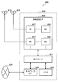
- FIG. 8 is an explanatory diagram illustrating an example of a schematic configuration of the system 1 according to the embodiment of the present disclosure.
- the system 1 includes a base station 100, a terminal device 200, and a base station 300.
- the system 1 is, for example, a system that complies with LTE, LTE-Advanced, or a communication standard based on these.
- the base station 100 performs wireless communication with the terminal device 200.
- the base station 100 performs wireless communication with the terminal device 200 located in the cell 101 of the base station 100.
- the base station 100 performs beam forming.
- the beam forming is large-scale MIMO beam forming.
- the beam forming may also be referred to as massive MIMO beam forming, free dimension MIMO beam forming, or three-dimensional beam forming.
- the base station 100 includes a directional antenna that can be used for large-scale MIMO, and performs large-scale MIMO beamforming by multiplying a transmission signal by a weight set for the directional antenna. .
- the base station 100 transmits a reference signal for channel quality measurement using a directional beam.
- the reference signal is CSI-RS. Note that the embodiment of the present disclosure is not limited to such an example, and the base station 100 may transmit the reference signal without beamforming.
- the terminal device 200 performs wireless communication with the base station. For example, when the terminal device 200 is located in the cell 101 of the base station 100, the terminal device 200 performs wireless communication with the base station 100. For example, when the base station 200 is located in the cell 301 of the base station 300, the base station 200 performs wireless communication with the base station 300.
- the terminal devices 200A, 200B, 200C, and 200D are connected to the base station 100. That is, the base station 100 is a serving base station for the terminal devices 200A, 200B, 200C, and 200D, and the cell 101 is a serving cell for the terminal devices 200A, 200B, 200C, and 200D.
- the terminal devices 200E, 200F, 200G, and 200H are connected to the base station 300. That is, the base station 300 is a serving base station for the terminal devices 200E, 200F, 200G, and 200H, and the cell 301 is a serving cell for the terminal devices 200E, 200F, 200G, and 200H.
- Base station 300 is a neighbor base station of base station 100. It can be said that the base station 100 is a peripheral base station of the base station 300.
- the base station 300 has the same configuration as the base station 100 and performs the same operation as the base station 100.
- the base station 100 also has the same configuration as the base station 300 and performs the same operation as the base station 300.
- FIG. 8 shows only the base station 300 as the peripheral base station of the base station 100, but the system 1 may include a plurality of peripheral base stations of the base station 100 as a matter of course.
- both the base station 100 and the base station 300 may be macrocell base stations. Alternatively, both the base station 100 and the base station 300 may be small cell base stations. Alternatively, one of the base station 100 and the base station 300 may be a macro cell base station, and the other of the base station 100 and the base station 300 may be a small cell base station.
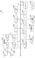
- FIG. 9 is a block diagram illustrating an exemplary configuration of the base station 100 according to the embodiment of the present disclosure.
- the base station 100 includes an antenna unit 110, a wireless communication unit 120, a network communication unit 130, a storage unit 140, and a processing unit 150.
- the antenna unit 110 radiates the signal output from the wireless communication unit 120 to the space as a radio wave. Further, the antenna unit 110 converts radio waves in space into a signal and outputs the signal to the wireless communication unit 120.
- the antenna unit 110 includes a directional antenna.
- the directional antenna is a directional antenna that can be used for large scale MIMO.
- the wireless communication unit 120 transmits and receives signals.
- the radio communication unit 120 transmits a downlink signal to the terminal device 200 and receives an uplink signal from the terminal device 200.
- the network communication unit 130 transmits and receives information.
- the network communication unit 130 transmits information to other nodes and receives information from other nodes.
- the other nodes include other base stations (eg, base station 300) and core network nodes.
- the storage unit 140 stores a program and data for the operation of the base station 100.
- the processing unit 150 provides various functions of the base station 100.
- the processing unit 150 includes an information acquisition unit 151 and a control unit 153.
- the processing unit 150 may further include other components other than these components. That is, the processing unit 150 can perform operations other than the operations of these components.
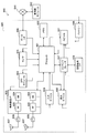
- FIG. 10 is a block diagram illustrating an example of a configuration of the terminal device 200 according to the embodiment of the present disclosure.
- the terminal device 200 includes an antenna unit 210, a wireless communication unit 220, a storage unit 230, and a processing unit 240.
- the antenna unit 210 radiates the signal output from the wireless communication unit 220 to the space as a radio wave. Further, the antenna unit 210 converts a radio wave in the space into a signal and outputs the signal to the wireless communication unit 220.
- the wireless communication unit 220 transmits and receives signals.
- the radio communication unit 220 receives a downlink signal from the base station and transmits an uplink signal to the base station.
- the storage unit 230 stores a program and data for the operation of the terminal device 200.
- the processing unit 240 provides various functions of the terminal device 200.
- the processing unit 240 includes an interference amount calculating unit 241, a detecting unit 243, and a reporting unit 245. Note that the processing unit 240 may further include other components other than these components. That is, the processing unit 240 can perform operations other than the operations of these components.
- the terminal device 200 (interference amount calculation unit 241) connected to the base station 300 transmits a reference signal (for example, a channel quality measurement reference signal transmitted by the base station 100)
- the amount of interference of the directional beam is calculated from (CSI-RS).
- the base station 100 transmits a channel quality measurement reference signal using each of a plurality of directional beams that the base station 100 can form.
- the terminal device 200 calculates the interference amount of each of the plurality of directional beams from the channel quality measurement reference signal transmitted by each of the plurality of directional beams.
- the configuration of the reference signal for channel quality measurement for example, radio resources and / or signals used for transmission
- the base station 100 may transmit a reference signal for channel quality measurement without beamforming.
- the terminal apparatus 200 estimates a channel from the reference signal, and each of the plurality of directional beams is based on the channel and a plurality of precoding matrices respectively corresponding to the plurality of directional beams.
- the base station 300 uses the channels reported by the terminal device 200 (reporting unit 245) and the interferences of the plurality of directional beams based on the plurality of precoding matrices. The amount may be calculated virtually.
- the base station 300 (that is, a base station around the base station 100) includes the base station 300 among a plurality of directional beams that can be formed by the base station 100.
- the base station 100 is provided with information on a directional beam that is an interference source for the terminal device 200 connected to the base station 100 (hereinafter referred to as “interference beam information”).
- Directional beam serving as an interference source is a directional beam having a large amount of interference in the terminal device 200.
- the base station 300 Information (ie, interference beam information) is provided to the base station 100.
- the base station 300 determines whether the interference amount of the directional beam is large based on the interference amount of the directional beam reported by the terminal device 200 (report unit 245) (for example, Whether the amount of interference exceeds a threshold value).
- the base station 300 determines that the amount of interference of the directional beam is large (for example, the amount of interference exceeds a threshold)
- the base station 300 transmits information on the directional beam (that is, interference beam information) to the base station. 100.
- the terminal device 200 may determine whether the interference amount of the directional beam is large (for example, whether the interference amount exceeds a threshold). Then, when determining that the amount of interference of the directional beam is large (for example, the amount of interference exceeds a threshold), the terminal device 200 (report unit 245) reports the directional beam to the base station 300. May be.
- the base station 300 may provide the base station 100 with information on the directional beam (that is, interference beam information).
- the directional beam serving as an interference source for the terminal device 200 may be a directional beam for which the amount of interference in the terminal device 200 is calculated.
- the base station 300 provides the base station 100 with information on the directional beam (that is, interference beam information) for which the amount of interference in the terminal device 200 is calculated regardless of whether the amount of interference is large or small. Also good.
- the base station 100 may determine whether the interference amount of the directional beam is large (for example, whether the interference amount exceeds a threshold).
- the directional beam serving as an interference source for the terminal device 200 may be a directional beam that prevents detection of other reference signals for channel quality measurement in the terminal device 200.
- the other reference signal may be a reference signal transmitted by another base station in the same radio resource as the reference signal transmitted by the base station 100.
- the base station 300 provides the base station 100 with information on the directional beam (that is, interference beam information). May be.
- the interference beam information includes information for specifying the directional beam (hereinafter referred to as “specific information”).
- the specific information is information (for example, PMI) indicating a precoding matrix used for forming the directional beam.
- a reference signal for channel quality measurement may be transmitted by a directional beam, and a configuration of a reference signal for channel quality measurement may be prepared for each directional beam. . That is, the directional beam and the configuration may be associated with each other.
- the specific information may be information indicating the configuration of a reference signal for channel quality measurement.
- the base station 300 can know the directional beam to be handled.
- the interference beam information may include information indicating the interference amount of the directional beam.
- the interference amount may be the interference amount of the directional beam in the terminal device 200 connected to the base station 300. Thereby, for example, the base station 300 can execute an operation according to the amount of interference.
- the base station 300 generates a message (message addressed to the base station 100) including the interference beam information. Then, the base station 300 transmits the message to the base station 100.
- the base station 100 (information acquisition unit 151) can form the interference beam information (that is, the base station 100) provided by the base station 300.
- the interference beam information that is, the base station 100
- the base station 100 determines the operation of the base station 100 related to signal transmission by the directional beam based on the interference beam information.
- the signal includes a data signal.
- the signal includes a reference signal for channel quality measurement.
- the reference signal is a channel state information reference signal (CSI-RS).
- CSI-RS channel state information reference signal
- the base station 100 determines and stops the transmission of the data signal and / or the reference signal by the directional beam.
- the interference of the directional beam in the terminal apparatus 200 connected to the base station 300 can be eliminated.
- the base station 100 determines the restriction on the transmission of the signal by the directional beam as the operation. And the base station 100 restrict
- the restriction includes restricting radio resources for transmitting the data signal by the directional beam. That is, the base station 100 (the control unit 153) determines to limit the radio resource for transmitting the data signal using the directional beam, and limits the radio resource. As a result, the base station 100 transmits a data signal using the directional beam with limited radio resources.
- the limitation includes limiting a time resource for transmitting a data signal by the directional beam.
- the time resource is a subframe.
- the base station 100 transmits a data signal using the directional beam in a limited subframe.
- the limitation may include limiting frequency resources for transmitting data signals by the directional beam.
- the limitation may include limiting time and frequency resources for transmitting a data signal by the directional beam.
- the restriction includes extending a period of transmitting a reference signal for channel quality measurement using the directional beam. That is, the base station 100 (control unit 153) decides to increase the period for transmitting the reference signal for channel quality measurement using the directional beam, and lengthens the period. That is, the base station 100 (control unit 153) changes the period of the configuration of the reference signal for channel quality measurement transmitted by the directional beam to a longer period.
- (B-3) Third example (continuation)
- the base station 100 determines to continue transmission of the signal by the directional beam as the operation. Then, the base station 100 continuously transmits the signal using the directional beam.
- the transmission of the signal by the directional beam can be continued.
- (B-4) Others The above limitation is the configuration of a reference signal for channel quality measurement using the directional beam (for example, radio resources (including period) used for signal transmission and / or signal sequence) May be included. That is, the base station 100 (the control unit 153) may determine to change the configuration and change the configuration.
- a reference signal for channel quality measurement using the directional beam for example, radio resources (including period) used for signal transmission and / or signal sequence
- the directional beam may be a directional beam that prevents detection of other reference signals (for example, other CSI-RSs) for channel quality measurement in the terminal device 200.
- the base station 100 the control unit 153 may decide to change the configuration and change the configuration.
- the terminal device 200 connected to the base station 300 can detect another reference signal for channel quality measurement.
- the base station 100 determines the operation of the base station 100 from various operations as described above.
- the control unit 153 determines the operation of the base station 100 from various operations as described above.
- an example of the method for determining the operation will be described.
- the determination of the operation according to the present embodiment is not limited to these examples.
- the base station 100 does not transmit a data signal to any of the terminal devices 200 by the directional beam.
- the base station 100 (the control unit 153) determines and stops the transmission of the data signal by the directional beam.
- the base station 100 transmits data signals to a small number of terminal devices 200 (for example, a predetermined number or less of terminal devices 200) using the directional beam.
- the base station 100 determines and executes a restriction on transmission of the data signal by the directional beam (for example, restriction on a radio resource for transmitting the data signal by the directional beam). To do.
- the base station 100 transmits data signals to a large number of terminal devices 200 (for example, more than a predetermined number of terminal devices 200) using the directional beam.
- the base station 100 (the control unit 153) determines and executes the continuation of the data signal transmission by the directional beam.
- the number of terminal devices 200 connected to the base station 100 and located in the radiation direction of the directional beam is small. More specifically, for example, the number of terminal devices 200 positioned in the radiation direction of the directional beam is a predetermined number or less.
- the base station 100 determines and stops the transmission or stop of transmission of the data signal and / or the channel quality measurement reference signal by the directional beam.
- the number of terminal devices 200 connected to the base station 100 and located in the radiation direction of the directional beam is large. More specifically, for example, the number of terminal devices 200 positioned in the radiation direction of the directional beam exceeds a predetermined number.
- the base station 100 determines and executes transmission of the data signal and / or the channel quality measurement reference signal by the directional beam.
- the predetermined number may be 1 or more, or may be 0.
- the base station 100 determines the operation of the base station 100 regarding the transmission of the signal by the directional beam based on the interference beam information. Thereby, for example, it becomes possible to reduce interference of directional beams between cells (that is, between the cell 101 and the cell 301).
- the base station 100 (the control unit 153) notifies the base station 300 of the operation of the base station 100 related to the transmission of the signal by the directional beam.
- the base station 100 (control unit 153) includes a message including operation information indicating the above-described operation (for example, stop, limit, or continue) of the base station 100 related to signal transmission by the directional beam. (Message addressed to base station 300) is generated. Then, the base station 100 transmits the message to the base station 300 via an interface (eg, X2 interface) between the base station 100 and the base station 300.
- operation information indicating the above-described operation (for example, stop, limit, or continue) of the base station 100 related to signal transmission by the directional beam.
- Message addressed to base station 300 is generated.
- the base station 100 transmits the message to the base station 300 via an interface (eg, X2 interface) between the base station 100 and the base station 300.
- the base station 300 it becomes possible for the base station 300 to know how the directional beam interference changes in the terminal device 200 connected to the base station 300.
- the base station 100 may notify the base station 300 of the operation of the base station 100 related to the transmission of signals by the directional beam.
- the base station 100 determines and executes a change in the configuration of the reference signal for channel quality measurement transmitted by the directional beam (including increasing the period) as the above operation. Also good. In this case, the base station 100 may notify the terminal device 200 of the change of the configuration.
- the base station 100 (the control unit 153) cancels the operation of the base station 100 related to the transmission of the signal by the directional beam when the cancellation condition is satisfied.
- the operation is stopping or limiting the transmission of the signal by the directional beam. Thereby, for example, it is possible to keep the stop or limit of transmission of the signal by the directional beam within a limited range.
- the release condition includes that the elapsed time from the start of the operation exceeds a predetermined time. That is, the base station 100 (control unit 153) cancels the operation when the elapsed time from the start of the operation exceeds a predetermined time.
- the base station 100 (the control unit 153) starts a timer at the start of the operation of the base station 100 related to transmission of a signal by the directional beam.
- the base station 100 (control unit 153) cancels the above operation.
- the release condition includes that the base station 100 receives release information related to the release of the operation from the base station 300. That is, when receiving the release information from the base station 300, the base station 100 (control unit 153) releases the operation.
- the base station 300 generates a release message including the release information and transmits the release message to the base station 100.
- the release information includes information for specifying the directional beam (that is, specification information).
- the release information may include restriction information indicating restriction on transmission of the signal by the directional beam after release.
- the restriction information may indicate a radio resource or a cycle for transmitting the signal by the directional beam as the restriction. Further, the restriction information may indicate a configuration of a reference signal for channel quality measurement transmitted by the directional beam as the restriction.
- the base station 100 may transmit the signal using the directional beam according to the restriction indicated by the restriction information after the cancellation of the operation.
- (B-2) Trigger of cancellation information transmission
- the base station 300 transmits the cancellation information to the base station 100 when it is assumed that the interference of the directional beam is small.
- the base station 300 When the terminal device 200 that receives the interference of the directional beam (the terminal device 200 connected to the base station 300) finishes receiving the data signal, the base station 300 The release information is transmitted to the base station 100.
- a terminal device 200 (a terminal device 200 connected to the base station 300) that receives interference of the directional beam at a certain position moves from the certain position to another position.
- the base station 300 transmits the release information to the base station 100.
- the terminal device 200 connected to the base station 300 detects a radio resource with a small amount of interference among radio resources to which a channel quality measurement reference signal is transmitted. May be.
- the base station 300 may transmit to the base station 100 release information related to the stop or restriction of the channel quality measurement reference signal.
- the cancellation information may include information indicating a configuration including the radio resource as limitation information indicating limitation of transmission of a reference signal for channel quality measurement by the directional beam after cancellation. Thereafter, the base station 100 may transmit a channel quality measurement reference signal having the configuration by the directional beam.
- the terminal device 200 receives a reference signal for channel quality measurement transmitted by a peripheral base station (including peripheral base stations other than the base station 100) of the base station 300 that is a serving base station. The amount of interference may be calculated. Thereafter, the terminal device 200 (detection unit 243) may detect a radio resource with a small amount of interference (for example, a radio resource with a smaller amount of interference than a threshold) among the radio resources to which the reference signal is transmitted. . Then, the terminal device 200 (report unit 245) may report the radio resource with a small amount of interference to the base station 300. Thereafter, the base station 300 may transmit release information to the base station 100, and the release information may include information indicating a configuration including the radio resource as restriction information.
- the trigger for transmitting the release information to the base station 100 is not limited to the first to third examples described above, and may be another trigger.
- the base station 100 (the control unit 153) notifies the base station 300 of completion of cancellation of the above operation.
- the base station 100 (the control unit 153) transmits a message including release completion information indicating completion of release of the above operation to the base station 300.
- the base station 100 may notify the terminal device 200 of the completion of the cancellation of the above operation.
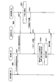
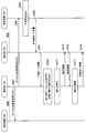
- FIG. 11 is a sequence diagram illustrating a first example of a schematic flow of a process according to an embodiment of the present disclosure.
- the base station 100 transmits a reference signal (for example, CSI-RS) for channel quality measurement (S401).
- a reference signal for example, CSI-RS
- S401 channel quality measurement
- the terminal device 200 connected to the base station 300 calculates an interference amount from the reference signal (S403). For example, the terminal device 200 calculates the amount of interference of each of a plurality of directional beams that can be formed by the base station 100.
- the terminal device 200 reports the interference amount to the base station 300 (S405).
- the terminal device 200 transmits an interference report indicating the amount of interference to the base station 300.
- the base station 300 relates to a directional beam that becomes an interference source for the terminal device 200 connected to the base station 300 (for example, a directional beam having a large amount of interference in the terminal device 200) among the plurality of directional beams.
- Information (that is, interference beam information) is provided to the base station 100 (S407).
- the base station 300 transmits a message including the interference beam information to the base station 100.
- the base station 100 acquires the interference beam information, and determines the operation of the base station 100 regarding signal transmission by the directional beam based on the interference beam information (S409). Then, the base station 100 performs the operation (S411). Further, the base station 100 notifies the above operation to the base station 300 (S413). For example, the base station 100 transmits a message including operation information indicating the above operation to the base station 300.
- the base station 100 may notify the terminal device 200 connected to the base station 100 of the above operation.
- the base station 300 may notify the terminal device 200 connected to the base station 300 of the above operation.
- FIG. 12 is a sequence diagram illustrating a second example of a schematic flow of processing according to the embodiment of the present disclosure.
- steps S431 to S441 and S445 in the second example shown in FIG. 12 is the same as the description of S401 to S413 in the first example shown in FIG. Therefore, only steps S443 and S447 to S451 will be described here.
- the base station 100 starts a timer at the start of an operation related to signal transmission by a directional beam (that is, the operation determined in step S431) (S443).
- the base station 100 cancels the operation (S449). Then, the base station 100 notifies the base station 300 of the completion of the cancellation of the operation (S451). For example, the base station 100 transmits a message including release completion information indicating the completion of the release of the operation to the base station 300.
- the base station 100 may notify the terminal device 200 connected to the base station 100 of the completion of the cancellation of the operation.
- the base station 300 may notify the terminal device 200 connected to the base station 300 of the completion of the cancellation of the operation.
- FIG. 13 is a sequence diagram illustrating a third example of a schematic flow of processing according to the embodiment of the present disclosure.
- steps S461 to S473 in the third example shown in FIG. 13 is the same as the description of S401 to S413 in the first example shown in FIG. Therefore, only steps S475 to S479 will be described here.
- the base station 300 transmits to the base station 100 release information related to the release of the operation related to signal transmission by the directional beam (that is, the operation determined in step S469) (S475). For example, the base station 300 transmits a release message including the release information to the base station 100.
- the base station 100 cancels the operation in response to the reception of the cancellation information (S477). Then, the base station 100 notifies the base station 300 of the completion of the cancellation of the operation (S479). For example, the base station 100 transmits a message including release completion information indicating the completion of the release of the operation to the base station 300.
- the base station 100 may notify the terminal device 200 connected to the base station 100 of the completion of the cancellation of the operation.
- the base station 300 may notify the terminal device 200 connected to the base station 300 of the completion of the cancellation of the operation.
- the base station 100 may be realized as any type of eNB (evolved Node B) such as a macro eNB or a small eNB.
- the small eNB may be an eNB that covers a cell smaller than a macro cell, such as a pico eNB, a micro eNB, or a home (femto) eNB.
- the base station 100 may be realized as another type of base station such as a NodeB or a BTS (Base Transceiver Station).
- Base station 100 may include a main body (also referred to as a base station apparatus) that controls radio communication, and one or more RRHs (Remote Radio Heads) that are arranged at locations different from the main body. Further, various types of terminals described later may operate as the base station 100 by temporarily or semi-permanently executing the base station function. Furthermore, at least some components of the base station 100 may be realized in a base station apparatus or a module for the base station apparatus.
- RRHs Remote Radio Heads
- the terminal device 200 is a smartphone, a tablet PC (Personal Computer), a notebook PC, a portable game terminal, a mobile terminal such as a portable / dongle type mobile router or a digital camera, or an in-vehicle terminal such as a car navigation device. It may be realized as.
- the terminal device 200 may be realized as a terminal (also referred to as an MTC (Machine Type Communication) terminal) that performs M2M (Machine To Machine) communication.
- MTC Machine Type Communication
- M2M Machine To Machine
- at least a part of the components of the terminal device 200 may be realized in a module (for example, an integrated circuit module configured by one die) mounted on these terminals.
- FIG. 14 is a block diagram illustrating a first example of a schematic configuration of an eNB to which the technology according to the present disclosure may be applied.
- the eNB 800 includes one or more antennas 810 and a base station device 820. Each antenna 810 and the base station apparatus 820 can be connected to each other via an RF cable.
- Each of the antennas 810 has a single or a plurality of antenna elements (for example, a plurality of antenna elements constituting a MIMO antenna), and is used for transmission and reception of radio signals by the base station apparatus 820.
- the eNB 800 includes a plurality of antennas 810 as illustrated in FIG. 14, and the plurality of antennas 810 may respectively correspond to a plurality of frequency bands used by the eNB 800, for example.
- FIG. 14 illustrates an example in which the eNB 800 includes a plurality of antennas 810, the eNB 800 may include a single antenna 810.
- the base station apparatus 820 includes a controller 821, a memory 822, a network interface 823, and a wireless communication interface 825.
- the controller 821 may be a CPU or a DSP, for example, and operates various functions of the upper layer of the base station apparatus 820. For example, the controller 821 generates a data packet from the data in the signal processed by the wireless communication interface 825, and transfers the generated packet via the network interface 823. The controller 821 may generate a bundled packet by bundling data from a plurality of baseband processors, and may transfer the generated bundled packet. In addition, the controller 821 is a logic that executes control such as radio resource control, radio bearer control, mobility management, inflow control, or scheduling. May have a typical function. Moreover, the said control may be performed in cooperation with a surrounding eNB or a core network node.
- the memory 822 includes RAM and ROM, and stores programs executed by the controller 821 and various control data (for example, terminal list, transmission power data, scheduling data, and the like).
- the network interface 823 is a communication interface for connecting the base station device 820 to the core network 824.
- the controller 821 may communicate with the core network node or other eNB via the network interface 823.
- the eNB 800 and the core network node or another eNB may be connected to each other by a logical interface (for example, an S1 interface or an X2 interface).
- the network interface 823 may be a wired communication interface or a wireless communication interface for wireless backhaul.
- the network interface 823 may use a frequency band higher than the frequency band used by the wireless communication interface 825 for wireless communication.
- the wireless communication interface 825 supports any cellular communication scheme such as LTE (Long Term Evolution) or LTE-Advanced, and provides a wireless connection to terminals located in the cell of the eNB 800 via the antenna 810.
- the wireless communication interface 825 may typically include a baseband (BB) processor 826, an RF circuit 827, and the like.
- the BB processor 826 may perform, for example, encoding / decoding, modulation / demodulation, and multiplexing / demultiplexing, and each layer (for example, L1, MAC (Medium Access Control), RLC (Radio Link Control), and PDCP).
- Various signal processing of Packet Data Convergence Protocol
- Packet Data Convergence Protocol is executed.
- the BB processor 826 may have some or all of the logical functions described above instead of the controller 821.
- the BB processor 826 may be a module that includes a memory that stores a communication control program, a processor that executes the program, and related circuits. The function of the BB processor 826 may be changed by updating the program. Good.
- the module may be a card or a blade inserted into a slot of the base station apparatus 820, or a chip mounted on the card or the blade.
- the RF circuit 827 may include a mixer, a filter, an amplifier, and the like, and transmits and receives a radio signal via the antenna 810.
- the wireless communication interface 825 includes a plurality of BB processors 826 as illustrated in FIG. 14, and the plurality of BB processors 826 may respectively correspond to a plurality of frequency bands used by the eNB 800, for example. Further, the wireless communication interface 825 includes a plurality of RF circuits 827 as illustrated in FIG. 14, and the plurality of RF circuits 827 may correspond to, for example, a plurality of antenna elements, respectively. 14 shows an example in which the wireless communication interface 825 includes a plurality of BB processors 826 and a plurality of RF circuits 827, the wireless communication interface 825 includes a single BB processor 826 or a single RF circuit 827. But you can.
- the information acquisition unit 151 and the control unit 153 described with reference to FIG. 8 may be implemented in the wireless communication interface 825. Alternatively, at least some of these components may be implemented in the controller 821.
- the eNB 800 includes a module including a part (for example, the BB processor 826) or all of the wireless communication interface 825 and / or the controller 821, and the information acquisition unit 151 and the control unit 153 are mounted in the module. Also good.
- the module stores a program for causing the processor to function as the information acquisition unit 151 and the control unit 153 (in other words, a program for causing the processor to execute operations of the information acquisition unit 151 and the control unit 153).
- the program may be executed.
- a program for causing a processor to function as the information acquisition unit 151 and the control unit 153 is installed in the eNB 800, and the wireless communication interface 825 (for example, the BB processor 826) and / or the controller 821 executes the program.
- the eNB 800, the base station apparatus 820, or the module may be provided as an apparatus including the information acquisition unit 151 and the control unit 153, and a program for causing the processor to function as the information acquisition unit 151 and the control unit 153 is provided. May be provided.
- a readable recording medium in which the program is recorded may be provided.
- the wireless communication unit 120 described with reference to FIG. 8 may be implemented in the wireless communication interface 825 (for example, the RF circuit 827). Further, the antenna unit 110 may be mounted on the antenna 810. The network communication unit 130 may be implemented in the controller 821 and / or the network interface 823.
- FIG. 15 is a block diagram illustrating a second example of a schematic configuration of an eNB to which the technology according to the present disclosure may be applied.
- the eNB 830 includes one or more antennas 840, a base station apparatus 850, and an RRH 860. Each antenna 840 and RRH 860 may be connected to each other via an RF cable. Base station apparatus 850 and RRH 860 can be connected to each other via a high-speed line such as an optical fiber cable.
- Each of the antennas 840 has a single or a plurality of antenna elements (for example, a plurality of antenna elements constituting a MIMO antenna), and is used for transmission / reception of radio signals by the RRH 860.
- the eNB 830 includes a plurality of antennas 840 as illustrated in FIG. 15, and the plurality of antennas 840 may respectively correspond to a plurality of frequency bands used by the eNB 830, for example. 15 illustrates an example in which the eNB 830 includes a plurality of antennas 840, but the eNB 830 may include a single antenna 840.
- the base station device 850 includes a controller 851, a memory 852, a network interface 853, a wireless communication interface 855, and a connection interface 857.
- the controller 851, the memory 852, and the network interface 853 are the same as the controller 821, the memory 822, and the network interface 823 described with reference to FIG.
- the wireless communication interface 855 supports a cellular communication method such as LTE or LTE-Advanced, and provides a wireless connection to a terminal located in a sector corresponding to the RRH 860 via the RRH 860 and the antenna 840.
- the wireless communication interface 855 may typically include a BB processor 856 and the like.
- the BB processor 856 is the same as the BB processor 826 described with reference to FIG. 14 except that it is connected to the RF circuit 864 of the RRH 860 via the connection interface 857.
- the wireless communication interface 855 includes a plurality of BB processors 856 as illustrated in FIG. 15, and the plurality of BB processors 856 may respectively correspond to a plurality of frequency bands used by the eNB 830, for example. 15 shows an example in which the wireless communication interface 855 includes a plurality of BB processors 856, the wireless communication interface 855 may include a single BB processor 856.
- connection interface 857 is an interface for connecting the base station device 850 (wireless communication interface 855) to the RRH 860.
- the connection interface 857 may be a communication module for communication on the high-speed line that connects the base station apparatus 850 (wireless communication interface 855) and the RRH 860.
- the RRH 860 includes a connection interface 861 and a wireless communication interface 863.
- connection interface 861 is an interface for connecting the RRH 860 (wireless communication interface 863) to the base station device 850.
- the connection interface 861 may be a communication module for communication on the high-speed line.
- the wireless communication interface 863 transmits and receives wireless signals via the antenna 840.
- the wireless communication interface 863 may typically include an RF circuit 864 and the like.
- the RF circuit 864 may include a mixer, a filter, an amplifier, and the like, and transmits and receives a radio signal via the antenna 840.
- the wireless communication interface 863 includes a plurality of RF circuits 864 as illustrated in FIG. 15, and the plurality of RF circuits 864 may correspond to, for example, a plurality of antenna elements, respectively. 15 illustrates an example in which the wireless communication interface 863 includes a plurality of RF circuits 864, the wireless communication interface 863 may include a single RF circuit 864.
- the information acquisition unit 151 and the control unit 153 described with reference to FIG. 8 may be implemented in the wireless communication interface 855 and / or the wireless communication interface 863. Alternatively, at least some of these components may be implemented in the controller 851. As an example, the eNB 830 includes a part of the wireless communication interface 855 (for example, the BB processor 856) or / and a module including the controller 851, and the information acquisition unit 151 and the control unit 153 are mounted in the module. Also good.
- the module stores a program for causing the processor to function as the information acquisition unit 151 and the control unit 153 (in other words, a program for causing the processor to execute operations of the information acquisition unit 151 and the control unit 153).
- the program may be executed.
- a program for causing a processor to function as the information acquisition unit 151 and the control unit 153 is installed in the eNB 830, and the wireless communication interface 855 (for example, the BB processor 856) and / or the controller 851 execute the program. Also good.
- the eNB 830, the base station apparatus 850, or the module may be provided as an apparatus including the information acquisition unit 151 and the control unit 153, and a program for causing the processor to function as the information acquisition unit 151 and the control unit 153 is provided. May be provided.
- a readable recording medium in which the program is recorded may be provided.
- the radio communication unit 120 described with reference to FIG. 8 may be implemented in the radio communication interface 863 (for example, the RF circuit 864).
- the antenna unit 110 may be mounted on the antenna 840.
- the network communication unit 130 may be implemented in the controller 851 and / or the network interface 853.
- FIG. 16 is a block diagram illustrating an example of a schematic configuration of a smartphone 900 to which the technology according to the present disclosure may be applied.
- the smartphone 900 includes a processor 901, a memory 902, a storage 903, an external connection interface 904, a camera 906, a sensor 907, a microphone 908, an input device 909, a display device 910, a speaker 911, a wireless communication interface 912, one or more antenna switches 915.
- One or more antennas 916, a bus 917, a battery 918 and an auxiliary controller 919 are provided.
- the processor 901 may be, for example, a CPU or a SoC (System on Chip), and controls the functions of the application layer and other layers of the smartphone 900.
- the memory 902 includes a RAM and a ROM, and stores programs executed by the processor 901 and data.
- the storage 903 can include a storage medium such as a semiconductor memory or a hard disk.
- the external connection interface 904 is an interface for connecting an external device such as a memory card or a USB (Universal Serial Bus) device to the smartphone 900.
- the camera 906 includes, for example, an image sensor such as a CCD (Charge Coupled Device) or a CMOS (Complementary Metal Oxide Semiconductor), and generates a captured image.
- the sensor 907 may include a sensor group such as a positioning sensor, a gyro sensor, a geomagnetic sensor, and an acceleration sensor.
- the microphone 908 converts sound input to the smartphone 900 into an audio signal.
- the input device 909 includes, for example, a touch sensor that detects a touch on the screen of the display device 910, a keypad, a keyboard, a button, or a switch, and receives an operation or information input from a user.
- the display device 910 has a screen such as a liquid crystal display (LCD) or an organic light emitting diode (OLED) display, and displays an output image of the smartphone 900.
- the speaker 911 converts an audio signal output from the smartphone 900 into audio.
- the wireless communication interface 912 supports any cellular communication method such as LTE or LTE-Advanced, and performs wireless communication.
- the wireless communication interface 912 may typically include a BB processor 913, an RF circuit 914, and the like.
- the BB processor 913 may perform, for example, encoding / decoding, modulation / demodulation, and multiplexing / demultiplexing, and performs various signal processing for wireless communication.
- the RF circuit 914 may include a mixer, a filter, an amplifier, and the like, and transmits and receives radio signals via the antenna 916.
- the wireless communication interface 912 may be a one-chip module in which the BB processor 913 and the RF circuit 914 are integrated.
- the wireless communication interface 912 may include a plurality of BB processors 913 and a plurality of RF circuits 914 as illustrated in FIG.
- FIG. 16 shows an example in which the wireless communication interface 912 includes a plurality of BB processors 913 and a plurality of RF circuits 914.
- the wireless communication interface 912 includes a single BB processor 913 or a single RF circuit 914. But you can.
- the wireless communication interface 912 may support other types of wireless communication methods such as a short-range wireless communication method, a proximity wireless communication method, or a wireless LAN (Local Area Network) method in addition to the cellular communication method.
- a BB processor 913 and an RF circuit 914 for each wireless communication method may be included.
- Each of the antenna switches 915 switches the connection destination of the antenna 916 among a plurality of circuits (for example, circuits for different wireless communication systems) included in the wireless communication interface 912.
- Each of the antennas 916 includes a single or a plurality of antenna elements (for example, a plurality of antenna elements constituting a MIMO antenna), and is used for transmission / reception of a radio signal by the radio communication interface 912.
- the smartphone 900 may include a plurality of antennas 916 as illustrated in FIG. 16 illustrates an example in which the smartphone 900 includes a plurality of antennas 916, the smartphone 900 may include a single antenna 916.
- the smartphone 900 may include an antenna 916 for each wireless communication method.
- the antenna switch 915 may be omitted from the configuration of the smartphone 900.
- the bus 917 connects the processor 901, memory 902, storage 903, external connection interface 904, camera 906, sensor 907, microphone 908, input device 909, display device 910, speaker 911, wireless communication interface 912, and auxiliary controller 919 to each other.
- the battery 918 supplies electric power to each block of the smartphone 900 shown in FIG. 16 through a power supply line partially shown by a broken line in the drawing.
- the auxiliary controller 919 operates the minimum necessary functions of the smartphone 900 in the sleep mode.
- the interference amount calculation unit 241, the detection unit 243, and / or the report unit 245 described with reference to FIG. 9 may be implemented in the wireless communication interface 912. Alternatively, at least some of these components may be implemented in the processor 901 or the auxiliary controller 919. As an example, the smartphone 900 includes a module including a part (for example, the BB processor 913) or the whole of the wireless communication interface 912, the processor 901, and / or the auxiliary controller 919, and the interference amount calculation unit 241 is detected in the module. Unit 243 and / or reporting unit 245 may be implemented.
- the module performs a program for causing the processor to function as the interference amount calculation unit 241, the detection unit 243, and / or the report unit 245 (in other words, the processor calculates the interference amount calculation unit 241, the detection unit 243, and / or the report).
- the program for executing the operation of the unit 245 may be stored and the program may be executed.
- a program for causing a processor to function as the interference amount calculation unit 241, the detection unit 243, and / or the report unit 245 is installed in the smartphone 900, and a wireless communication interface 912 (for example, a BB processor 913), a processor 901, And / or the auxiliary controller 919 may execute the program.
- the smartphone 900 or the module may be provided as a device including the interference amount calculation unit 241, the detection unit 243, and / or the report unit 245, and the processor may be provided with the interference amount calculation unit 241, the detection unit 243, and / or the processor.
- a program for causing the report unit 245 to function may be provided.
- a readable recording medium in which the program is recorded may be provided.
- the wireless communication unit 220 described with reference to FIG. 9 may be implemented in the wireless communication interface 912 (for example, the RF circuit 914).
- the antenna unit 210 may be mounted on the antenna 916.
- FIG. 17 is a block diagram illustrating an example of a schematic configuration of a car navigation device 920 to which the technology according to the present disclosure can be applied.
- the car navigation device 920 includes a processor 921, a memory 922, a GPS (Global Positioning System) module 924, a sensor 925, a data interface 926, a content player 927, a storage medium interface 928, an input device 929, a display device 930, a speaker 931, and wireless communication.
- the interface 933 includes one or more antenna switches 936, one or more antennas 937, and a battery 938.
- the processor 921 may be a CPU or SoC, for example, and controls the navigation function and other functions of the car navigation device 920.
- the memory 922 includes RAM and ROM, and stores programs and data executed by the processor 921.
- the GPS module 924 measures the position (for example, latitude, longitude, and altitude) of the car navigation device 920 using GPS signals received from GPS satellites.
- the sensor 925 may include a sensor group such as a gyro sensor, a geomagnetic sensor, and an atmospheric pressure sensor.
- the data interface 926 is connected to the in-vehicle network 941 through a terminal (not shown), for example, and acquires data generated on the vehicle side such as vehicle speed data.
- the content player 927 reproduces content stored in a storage medium (for example, CD or DVD) inserted into the storage medium interface 928.
- the input device 929 includes, for example, a touch sensor, a button, or a switch that detects a touch on the screen of the display device 930, and receives an operation or information input from the user.
- the display device 930 has a screen such as an LCD or an OLED display, and displays a navigation function or an image of content to be reproduced.
- the speaker 931 outputs the navigation function or the audio of the content to be played back.
- the wireless communication interface 933 supports any cellular communication method such as LTE or LTE-Advanced, and performs wireless communication.
- the wireless communication interface 933 may typically include a BB processor 934, an RF circuit 935, and the like.
- the BB processor 934 may perform, for example, encoding / decoding, modulation / demodulation, and multiplexing / demultiplexing, and performs various signal processing for wireless communication.
- the RF circuit 935 may include a mixer, a filter, an amplifier, and the like, and transmits and receives a radio signal via the antenna 937.
- the wireless communication interface 933 may be a one-chip module in which the BB processor 934 and the RF circuit 935 are integrated.
- the wireless communication interface 933 may include a plurality of BB processors 934 and a plurality of RF circuits 935 as shown in FIG. Note that although FIG. 17 illustrates an example in which the wireless communication interface 933 includes a plurality of BB processors 934 and a plurality of RF circuits 935, the wireless communication interface 933 includes a single BB processor 934 or a single RF circuit 935. But you can.
- the wireless communication interface 933 may support other types of wireless communication methods such as a short-range wireless communication method, a proximity wireless communication method, or a wireless LAN method in addition to the cellular communication method.
- a BB processor 934 and an RF circuit 935 may be included for each communication method.
- Each of the antenna switches 936 switches the connection destination of the antenna 937 among a plurality of circuits included in the wireless communication interface 933 (for example, circuits for different wireless communication systems).
- Each of the antennas 937 has a single or a plurality of antenna elements (for example, a plurality of antenna elements constituting a MIMO antenna), and is used for transmission / reception of a radio signal by the radio communication interface 933.
- the car navigation device 920 may include a plurality of antennas 937 as shown in FIG. Note that although FIG. 17 illustrates an example in which the car navigation device 920 includes a plurality of antennas 937, the car navigation device 920 may include a single antenna 937.
- the car navigation device 920 may include an antenna 937 for each wireless communication method.
- the antenna switch 936 may be omitted from the configuration of the car navigation device 920.
- the battery 938 supplies power to each block of the car navigation apparatus 920 shown in FIG. 17 through a power supply line partially shown by a broken line in the drawing. Further, the battery 938 stores electric power supplied from the vehicle side.
- the interference amount calculation unit 241, the detection unit 243, and / or the report unit 245 described with reference to FIG. 9 may be implemented in the wireless communication interface 933.
- the processor 921 may be implemented in the processor 921.
- the car navigation apparatus 920 includes a module including a part (for example, the BB processor 934) or all of the wireless communication interface 933 and / or the processor 921, and the interference amount calculation unit 241, the detection unit 243, and / Or a reporting unit 245 may be implemented.
- the module performs a program for causing the processor to function as the interference amount calculation unit 241, the detection unit 243, and / or the report unit 245 (in other words, the processor calculates the interference amount calculation unit 241, the detection unit 243, and / or the report).
- the program for executing the operation of the unit 245 may be stored and the program may be executed.
- a program for causing the processor to function as the interference amount calculation unit 241, the detection unit 243, and / or the report unit 245 is installed in the car navigation device 920, and the wireless communication interface 933 (for example, the BB processor 934) and / or Alternatively, the processor 921 may execute the program.
- the car navigation device 920 or the above module may be provided as a device including the interference amount calculation unit 241, the detection unit 243, and / or the report unit 245, and the processor may include the interference amount calculation unit 241, the detection unit 243, and the like.
- a program for functioning as the reporting unit 245 may be provided.
- a readable recording medium in which the program is recorded may be provided.
- the wireless communication unit 220 described with reference to FIG. 9 may be implemented in the wireless communication interface 933 (for example, the RF circuit 935).
- the antenna unit 210 may be mounted on the antenna 937.
- the technology according to the present disclosure may be realized as an in-vehicle system (or vehicle) 940 including one or more blocks of the car navigation device 920 described above, an in-vehicle network 941, and a vehicle side module 942. That is, the in-vehicle system (or vehicle) 940 may be provided as a device including the interference amount calculation unit 241, the detection unit 243, and / or the report unit 245.
- the vehicle-side module 942 generates vehicle-side data such as vehicle speed, engine speed, or failure information, and outputs the generated data to the in-vehicle network 941.
- the base station 100 is used for the terminal device 200 connected to the base station 300 (a peripheral base station of the base station 100) among a plurality of directional beams that can be formed by the base station 100.
- Information acquisition unit 151 that acquires the information provided by the base station 300, and the base station 100 related to transmission of a signal by the directional beam based on the information.
- a control unit 153 that determines the operation of.
- the communication system may be a system that complies with other communication standards.
- processing steps in the processing of the present specification do not necessarily have to be executed in time series according to the order described in the flowchart or the sequence diagram.
- the processing steps in the processing may be executed in an order different from the order described as a flowchart or a sequence diagram, or may be executed in parallel.
- a processor for example, a CPU, a DSP, or the like included in a device of the present specification (for example, a base station, a base station device, a module for a base station device, or a terminal device or a module for a terminal device) is provided. It is also possible to create a computer program (in other words, a computer program for causing the processor to execute the operation of the component of the device) to function as a component of the device (for example, an information acquisition unit and a control unit). . Moreover, a recording medium on which the computer program is recorded may be provided.
- An apparatus for example, a base station, a base station apparatus, a module for a base station apparatus, a terminal apparatus, or a device including a memory for storing the computer program and one or more processors capable of executing the computer program
- a module for a terminal device may also be provided.
- a method including the operation of the components of the device for example, an information acquisition unit and a communication control unit is also included in the technology according to the present disclosure.
- the following configurations also belong to the technical scope of the present disclosure.
- a base station information on a directional beam that is an interference source for a terminal device connected to a peripheral base station of the base station, and is provided by the peripheral base station
- An acquisition unit for acquiring the information A control unit that determines an operation of the base station related to transmission of a signal by the directional beam based on the information;
- a device comprising: (2) The apparatus according to (1), wherein the signal includes a data signal.
- the signal includes a reference signal for channel quality measurement.
- the reference signal for channel quality measurement is a channel state information reference signal (CSI-RS).
- CSI-RS channel state information reference signal
- the device includes that the base station receives release information related to the release of the operation from the neighboring base station.
- the said cancellation information is an apparatus as described in said (15) including the restriction information which shows the restriction
- the restriction information includes the restriction, Radio resource or period for transmitting the signal by the directional beam, or A configuration of a reference signal for channel quality measurement transmitted by the directional beam is shown.
- the apparatus (16) above.
- the apparatus according to any one of (1) to (17), wherein the apparatus is the base station, a base station apparatus for the base station, or a module for the base station apparatus.
- a calculation unit that calculates an interference amount from a reference signal for channel quality measurement transmitted by a neighboring base station of the serving base station;
- a detection unit that detects a radio resource with a small amount of interference among radio resources to which the reference signal is transmitted;
- a reporting unit for reporting the radio resource with a small amount of interference to a base station;
- a device comprising: (21) Of a plurality of directional beams that can be formed by a base station, information on a directional beam that is an interference source for a terminal device connected to a peripheral base station of the base station, and is provided by the peripheral base station Obtaining said information; Determining the operation of the base station with respect to the transmission of signals by the directional beam based on the information;
- a program that causes a processor to execute.
- System 100 Base Station 101 Cell 151 Information Acquisition Unit 153 Control Unit 200 Terminal Device 241 Interference Calculation Unit 243 Detection Unit 245 Report Unit 300 Base Station 301 Cell
Landscapes
- Engineering & Computer Science (AREA)
- Signal Processing (AREA)
- Computer Networks & Wireless Communication (AREA)
- Mobile Radio Communication Systems (AREA)
Abstract
Description
1.はじめに
1.1.関連技術
1.2.本実施形態に関連する考察
2.システムの概略的な構成
3.各装置の構成
3.1.基地局の構成
3.2.端末装置の構成
4.技術的特徴
5.処理の流れ
6.応用例
6.1.基地局に関する応用例
6.2.端末装置に関する応用例
7.まとめ
まず、図1~図7を参照して、本開示の実施形態に関連する技術、及び、本実施形態に関連する考察を説明する。
図1~図4を参照して、本開示の実施形態に関連する技術として、ビームフォーミング及び測定(measurement)を説明する。
(a)ラージスケールMIMOの必要性
現在、3GPPでは、爆発的に増加するトラフィックを収容するために、セルラーシステムの容量を向上するための様々な技術が検討されている。将来、現在の1000倍程度の容量が必要とも言われている。MU-MIMO及びCoMPなどの技術では、セルラーシステムの容量は数倍程度しか増加しないと考えられる。そのため、画期的な手法が求められている。
ビームフォーミング用の重みセット(即ち、複数のアンテナ素子のための重み係数のセット)は、複素数として表される。以下、図1を参照して、とりわけラージスケールMIMOのビームフォーミング用の重みセットの例を説明する。


ラージスケールMIMOのビームフォーミングが行われる場合には、利得は10dB以上に達する。上記ビームフォーミングを採用するセルラーシステムでは、従来のセルラーシステムと比べて、電波環境の変化が激しくなり得る。
例えば、都市部の基地局が高層ビルに向けたビームを形成することが考えられる。また、郊外であっても、スモールセルの基地局が当該基地局の周辺のエリアに向けたビームを形成することが考えられる。なお、郊外のマクロセルの基地局はラージスケールMIMOのビームフォーミングを行わない可能性が高い。
測定には、セルを選択するための測定と、接続後にCQI(Channel Quality Indicator)などをフィードバックするための測定とがある。後者の測定は、より短い時間で行われることが求められる。サービングセルの品質の測定のみではなく、周辺セル(neighbor cell)からの干渉量の測定も、このCQI測定の一種であると考えられている。
CQI測定のために、CRS(Cell-specific Reference Signal)が使用され得るが、リリース10以降では、CQI測定のために、主としてCSI-RS(Channel State Information Reference Signal)が使用される。
リリース12までは、上述したように、CSI-RSは、ビームフォーミングなしで送信されるので、CSI-RSについての測定が行われると、ビームフォーミングの影響を受けていない素のチャネルHが推定される。そのため、CSI-RSは、CRSと同様の働きをしていた。
図5~図7を参照して、本開示の実施形態に関連する考察を説明する。
(a)セル内での干渉
eNBが形成する指向性ビームが反射しない環境では、当該eNBが形成する指向性ビームの間で干渉は発生しない。一方、eNBが形成する指向性ビームが反射する環境では、当該eNBが形成する指向性ビームの間で干渉が発生し得る。以下、この点について図5及び図6を参照して具体例を説明する。
セル内の指向性ビームの間での干渉のみではなく、異なるセルの指向性ビーム間での干渉も発生し得る。以下、この点について図7を参照して具体例を説明する。
上述したように、セル内での指向性ビームの干渉、及び/又はセル間での指向性ビームの干渉が発生すると、UEの受信品質が低下し、その結果、システムスループットが低下し得る。
所望の指向性ビームのみがUEに到達する場合には、当該UEは良好な受信品質を得ることができる。一方、所望の指向性ビームのみではなく、他の指向性ビームもUEに到達する場合には、当該UEにおける受信品質が悪化し得る。
CSI-RSは、リリース10で規定されている。通常のCSI-RSは、非ゼロパワー(Non zero power)CSI-RSとも呼ばれる。CSI-RSの目的は、素のチャネルを取得することなので、CSI-RSはビームフォーミングなしで送信される。
続いて、図8を参照して、本開示の実施形態に係るシステム1の概略的な構成を説明する。図8は、本開示の実施形態に係るシステム1の概略的な構成の一例を示す説明図である。図8を参照すると、システム1は、基地局100、端末装置200及び基地局300を含む。システム1は、例えば、LTE、LTE-Advanced、又はこれらに準ずる通信規格に準拠したシステムである。
基地局100は、端末装置200との無線通信を行う。例えば、基地局100は、基地局100のセル101内に位置する端末装置200との無線通信を行う。
端末装置200は、基地局との無線通信を行う。例えば、端末装置200は、基地局100のセル101内に位置する場合に、基地局100との無線通信を行う。例えば、基地局200は、基地局300のセル301内に位置する場合に、基地局300との無線通信を行う。
基地局300は、基地局100の周辺基地局(neighbor base station)である。基地局100が、基地局300の周辺基地局であるとも言える。
続いて、図9及び図10を参照して、基地局100及び端末装置200の構成の例を説明する。
まず、図9を参照して、本開示の実施形態に係る基地局100の構成の一例を説明する。図9は、本開示の実施形態に係る基地局100の構成の一例を示すブロック図である。図9を参照すると、基地局100は、アンテナ部110、無線通信部120、ネットワーク通信部130、記憶部140及び処理部150を備える。
アンテナ部110は、無線通信部120により出力された信号を電波として空間に放射する。また、アンテナ部110は、空間の電波を信号に変換し、当該信号を無線通信部120へ出力する。
無線通信部120は、信号を送受信する。例えば、無線通信部120は、端末装置200へのダウンリンク信号を送信し、端末装置200からのアップリンク信号を受信する。
ネットワーク通信部130は、情報を送受信する。例えば、ネットワーク通信部130は、他のノードへの情報を送信し、他のノードからの情報を受信する。例えば、上記他のノードは、他の基地局(例えば、基地局300)及びコアネットワークノードを含む。
記憶部140は、基地局100の動作のためのプログラム及びデータを記憶する。
処理部150は、基地局100の様々な機能を提供する。処理部150は、情報取得部151及び制御部153を含む。なお、処理部150は、これらの構成要素以外の他の構成要素をさらに含み得る。即ち、処理部150は、これらの構成要素の動作以外の動作も行い得る。
次に、図10を参照して、本開示の実施形態に係る端末装置200の構成の一例を説明する。図10は、本開示の実施形態に係る端末装置200の構成の一例を示すブロック図である。図10を参照すると、端末装置200は、アンテナ部210、無線通信部220、記憶部230及び処理部240を備える。
アンテナ部210は、無線通信部220により出力された信号を電波として空間に放射する。また、アンテナ部210は、空間の電波を信号に変換し、当該信号を無線通信部220へ出力する。
無線通信部220は、信号を送受信する。例えば、無線通信部220は、基地局からのダウンリンク信号を受信し、基地局へのアップリンク信号を送信する。
記憶部230は、端末装置200の動作のためのプログラム及びデータを記憶する。
処理部240は、端末装置200の様々な機能を提供する。処理部240は、干渉量算出部241、検出部243及び報告部245を含む。なお、処理部240は、これらの構成要素以外の他の構成要素をさらに含み得る。即ち、処理部240は、これらの構成要素の動作以外の動作も行い得る。
続いて、本開示の実施形態に係る技術的特徴を説明する。
例えば、基地局300に接続されている端末装置200(干渉量算出部241)は、基地局100により送信されるチャネル品質測定用のリファレンス信号(例えば、CSI-RS)から、指向性ビームの干渉量を算出する。
本開示の実施形態では、基地局300(即ち、基地局100の周辺基地局)は、基地局100が形成可能な複数の指向性ビームのうちの、基地局300に接続される端末装置200にとっての干渉源となる指向性ビームに関する情報(以下、「干渉ビーム情報」と呼ぶ)を、基地局100に提供する。
(a-1)干渉量が大きい指向性ビーム
例えば、端末装置200にとっての干渉源となる上記指向性ビームは、端末装置200における干渉量が大きい指向性ビーム(例えば、干渉量が閾値を超える指向性ビーム)である。この場合に、基地局300は、基地局300に接続されている端末装置200における干渉量が大きい指向性ビーム(例えば、干渉量が閾値を超える指向性ビーム)がある場合に、当該指向性ビームに関する情報(即ち、干渉ビーム情報)を基地局100に提供する。
端末装置200にとっての干渉源となる上記指向性ビームは、端末装置200における干渉量が算出される指向性ビームであってもよい。この場合に、基地局300は、干渉量が大きいか小さいかにかかわらず、端末装置200における干渉量が算出される指向性ビームに関する情報(即ち、干渉ビーム情報)を基地局100に提供してもよい。この場合に、基地局100が、指向性ビームの干渉量が大きいか(例えば、当該干渉量が閾値を超えるか)を判定してもよい。
端末装置200にとっての干渉源となる上記指向性ビームは、端末装置200におけるチャネル品質測定用の他のリファレンス信号の検出を妨げる指向性ビームであってもよい。上記他のリファレンス信号は、基地局100により送信される上記リファレンス信号と同じ無線リソースにおいて他の基地局により送信されるリファレンス信号であってもよい。この場合に、基地局300は、チャネル品質測定用の他のリファレンス信号の検出を妨げる指向性ビームがある場合に、当該指向性ビームに関する情報(即ち、干渉ビーム情報)を基地局100に提供してもよい。
(b-1)特定情報
例えば、上記干渉ビーム情報は、上記指向性ビームを特定するための情報(以下、「特定情報」と呼ぶ)を含む。
上記干渉ビーム情報は、上記指向性ビームの干渉量を示す情報を含んでもよい。当該干渉量は、基地局300に接続される端末装置200における上記指向性ビームの干渉量であってもよい。これにより、例えば、基地局300が、干渉量に応じた動作を実行することも可能になる。
例えば、基地局300は、上記干渉ビーム情報を含むメッセージ(基地局100宛のメッセージ)を生成する。そして、基地局300は、当該メッセージを基地局100へ送信する。
本開示の実施形態では、基地局100(情報取得部151)は、基地局300により提供される上記干渉ビーム情報(即ち、基地局100が形成可能な複数の指向性ビームのうちの、基地局300に接続される端末装置200にとっての干渉源となる指向性ビームに関する情報)を取得する。そして、基地局100(制御部153)は、上記干渉ビーム情報に基づいて、上記指向性ビームによる信号の送信に関する基地局100の動作を決定する。
例えば、上記信号は、データ信号を含む。
(b-1)第1の例(停止)
第1の例として、基地局100(制御部153)は、上記動作として、上記指向性ビームによる上記信号の送信の停止を決定する。そして、基地局100は、上記指向性ビームによる上記信号の送信を停止する。
第2の例として、基地局100(制御部153)は、上記動作として、上記指向性ビームによる上記信号の送信の制限を決定する。そして、基地局100は、上記指向性ビームによる上記信号の送信を制限する。
例えば、上記制限は、上記指向性ビームによりデータ信号を送信する無線リソースを制限することを含む。即ち、基地局100(制御部153)は、上記指向性ビームによりデータ信号を送信する無線リソースを制限することを決定し、当該無線リソースを制限する。その結果、基地局100は、制限された無線リソースにおいて上記指向性ビームによりデータ信号を送信する
例えば、上記制限は、上記指向性ビームによりチャネル品質測定用のリファレンス信号を送信する周期を長くすることを含む。即ち、基地局100(制御部153)は、上記指向性ビームによりチャネル品質測定用のリファレンス信号を送信する周期を長くすることを決定し、当該周期を長くする。即ち、基地局100(制御部153)は、上記指向性ビームにより送信されるチャネル品質測定用のリファレンス信号のコンフィギュレーションのうちの周期をより長い周期に変更する。
例えば、基地局100(制御部153)は、上記動作として、上記指向性ビームによる上記信号の送信の継続を決定する。そして、基地局100は、継続して、上記指向性ビームにより上記信号を送信する。
上記制限は、上記指向性ビームによりチャネル品質測定用のリファレンス信号のコンフィギュレーション(例えば、信号の送信に使用される無線リソース(周期を含む)、及び/又は信号のシーケンス)を変更することを含んでもよい。即ち、基地局100(制御部153)は、上記コンフィギュレーションを変更することを決定し、当該コンフィギュレーションを変更してもよい。
例えば、基地局100(制御部153)は、上述したような様々な動作の中から、基地局100の動作を決定する。以下、当該動作の決定手法の例を説明する。なお、本実施形態に係る当該動作の決定は、これらの例に限定されない。
例えば、基地局100は、いずれの端末装置200へも、上記指向性ビームによりデータ信号を送信していない。この場合に、例えば、基地局100(制御部153)は、上記指向性ビームによるデータ信号の送信の停止を決定し、実行する。
例えば、基地局100に接続され、且つ上記指向性ビームの放射方向に位置する端末装置200の数が少ない。より具体的には、例えば、上記指向性ビームの放射方向に位置する端末装置200の数が所定数以下である。この場合に、基地局100(制御部153)は、上記指向性ビームによるデータ信号及び/又はチャネル品質測定用のリファレンス信号の送信の停止又は制限を決定し、実行する。
(a)周辺基地局への通知
例えば、基地局100(制御部153)は、上記指向性ビームによる上記信号の送信に関する基地局100の上記動作を基地局300に通知する。
基地局100(制御部153)は、上記指向性ビームによる信号の送信に関する基地局100の上記動作を基地局300に通知してもよい。
例えば、基地局100(制御部153)は、解除条件が満たされる場合に、上記指向性ビームによる上記信号の送信に関する基地局100の上記動作を解除する。例えば、当該動作は、上記指向性ビームによる上記信号の送信の停止又は制限などである。これにより、例えば、上記指向性ビームによる上記信号の送信の停止又は制限を、限定的な範囲内に収めることが可能になる。
例えば、上記解除条件は、上記動作の開始からの経過時間が所定時間を超えることを含む。即ち、基地局100(制御部153)は、上記動作の開始からの経過時間が所定時間を超える場合に、上記動作を解除する。
例えば、上記解除条件は、基地局100が基地局300から上記動作の解除に関する解除情報を受信することを含む。即ち、基地局100(制御部153)は、基地局300から上記解除情報を受信する場合に、上記動作を解除する。
-ビーム情報
例えば、上記解除情報は、上記指向性ビームを特定するための情報(即ち、特定情報)を含む。
上記解除情報は、解除後の上記指向性ビームによる上記信号の送信の制限を示す制限情報を含んでもよい。
例えば、基地局300は、上記指向性ビームの干渉が小さいと想定される場合に、上記解除情報を基地局100へ送信する。
第1の例として、上記指向性ビームの干渉を受ける端末装置200(基地局300に接続されている端末装置200)がデータ信号の受信を終了する場合に、基地局300は、上記解除情報を基地局100へ送信する。
第2の例として、ある位置において上記指向性ビームの干渉を受ける端末装置200(基地局300に接続されている端末装置200)が、当該ある位置から別の位置に移動する場合に、基地局300は、上記解除情報を基地局100へ送信する。
第3の例として、基地局300に接続されている端末装置200が、チャネル品質測定用のリファレンス信号が送信される無線リソースのうちの、干渉量が少ない無線リソースを検出してもよい。この場合に、基地局300は、チャネル品質測定用のリファレンス信号の停止又は制限に関する解除情報を、基地局100へ送信してもよい。当該解除情報は、解除後の上記指向性ビームによるチャネル品質測定用のリファレンス信号の送信の制限を示す制限情報として、上記無線リソースを含むコンフィギュレーションを示す情報を含んでもよい。その後、基地局100は、当該コンフィギュレーションを有するチャネル品質測定用のリファレンス信号を上記指向性ビームにより送信してもよい。
例えば、基地局100(制御部153)は、上記動作の解除の完了を基地局300に通知する。例えば、基地局100(制御部153)は、上記動作の解除の完了を示す解除完了情報を含むメッセージを基地局300へ送信する。
続いて、図11~図13を参照して、本開示の実施形態に係る処理の例を説明する。
図11は、本開示の実施形態に係る処理の概略的な流れの第1の例を示すシーケンス図である。
図12は、本開示の実施形態に係る処理の概略的な流れの第2の例を示すシーケンス図である。
図13は、本開示の実施形態に係る処理の概略的な流れの第3の例を示すシーケンス図である。
本開示に係る技術は、様々な製品へ応用可能である。例えば、基地局100は、マクロeNB又はスモールeNBなどのいずれかの種類のeNB(evolved Node B)として実現されてもよい。スモールeNBは、ピコeNB、マイクロeNB又はホーム(フェムト)eNBなどの、マクロセルよりも小さいセルをカバーするeNBであってよい。その代わりに、基地局100は、NodeB又はBTS(Base Transceiver Station)などの他の種類の基地局として実現されてもよい。基地局100は、無線通信を制御する本体(基地局装置ともいう)と、本体とは別の場所に配置される1つ以上のRRH(Remote Radio Head)とを含んでもよい。また、後述する様々な種類の端末が一時的に又は半永続的に基地局機能を実行することにより、基地局100として動作してもよい。さらに、基地局100の少なくとも一部の構成要素は、基地局装置又は基地局装置のためのモジュールにおいて実現されてもよい。
(第1の応用例)
図14は、本開示に係る技術が適用され得るeNBの概略的な構成の第1の例を示すブロック図である。eNB800は、1つ以上のアンテナ810、及び基地局装置820を有する。各アンテナ810及び基地局装置820は、RFケーブルを介して互いに接続され得る。
図15は、本開示に係る技術が適用され得るeNBの概略的な構成の第2の例を示すブロック図である。eNB830は、1つ以上のアンテナ840、基地局装置850、及びRRH860を有する。各アンテナ840及びRRH860は、RFケーブルを介して互いに接続され得る。また、基地局装置850及びRRH860は、光ファイバケーブルなどの高速回線で互いに接続され得る。
(第1の応用例)
図16は、本開示に係る技術が適用され得るスマートフォン900の概略的な構成の一例を示すブロック図である。スマートフォン900は、プロセッサ901、メモリ902、ストレージ903、外部接続インタフェース904、カメラ906、センサ907、マイクロフォン908、入力デバイス909、表示デバイス910、スピーカ911、無線通信インタフェース912、1つ以上のアンテナスイッチ915、1つ以上のアンテナ916、バス917、バッテリー918及び補助コントローラ919を備える。
図17は、本開示に係る技術が適用され得るカーナビゲーション装置920の概略的な構成の一例を示すブロック図である。カーナビゲーション装置920は、プロセッサ921、メモリ922、GPS(Global Positioning System)モジュール924、センサ925、データインタフェース926、コンテンツプレーヤ927、記憶媒体インタフェース928、入力デバイス929、表示デバイス930、スピーカ931、無線通信インタフェース933、1つ以上のアンテナスイッチ936、1つ以上のアンテナ937及びバッテリー938を備える。
ここまで、図5~図17を参照して、本開示の実施形態に係る各装置及び各処理を説明した。
(1)
基地局が形成可能な複数の指向性ビームのうちの、当該基地局の周辺基地局に接続される端末装置にとっての干渉源となる指向性ビームに関する情報であって、前記周辺基地局により提供される前記情報を取得する取得部と、
前記情報に基づいて、前記指向性ビームによる信号の送信に関する前記基地局の動作を決定する制御部と、
を備える装置。
(2)
前記信号は、データ信号を含む、前記(1)に記載の装置。
(3)
前記信号は、チャネル品質測定用のリファレンス信号を含む、前記(1)又は(2)に記載の装置。
(4)
チャネル品質測定用の前記リファレンス信号は、チャネル状態情報リファレンス信号(CSI-RS)である、前記(3)に記載の装置。
(5)
前記制御部は、前記動作として、前記指向性ビームによる前記信号の送信の停止を決定する、前記(1)~(4)のいずれか1項に記載の装置。
(6)
前記制御部は、前記動作として、前記指向性ビームによる前記信号の送信の制限を決定する、前記(1)~(5)のいずれか1項に記載の装置。
(7)
前記制限は、前記指向性ビームによりデータ信号を送信する無線リソースを制限することを含む、前記(6)に記載の装置。
(8)
前記制限は、前記指向性ビームによりデータ信号を送信する時間リソースを制限することを含む、前記(7)に記載の装置。
(9)
前記制限は、前記指向性ビームによりチャネル品質測定用のリファレンス信号を送信する周期を長くすることを含む、前記(6)~(8)のいずれか1項に記載の装置。
(10)
前記制御部は、前記基地局の前記動作を前記周辺基地局に通知する、前記(1)~(9)のいずれか1項に記載の装置。
(11)
前記制御部は、前記基地局の前記動作を端末装置に通知する、前記(1)~(10)のいずれか1項に記載の装置。
(12)
前記指向性ビームに関する前記情報は、前記指向性ビームを特定するための情報を含む、前記(1)~(11)のいずれか1項に記載の装置。
(13)
前記制御部は、解除条件が満たされる場合に、前記基地局の前記動作を解除する、前記(1)~(12)のいずれか1項に記載の装置。
(14)
前記解除条件は、前記動作の開始からの経過時間が所定時間を超えることを含む、前記(13)に記載の装置。
(15)
前記解除条件は、前記基地局が前記周辺基地局から前記動作の解除に関する解除情報を受信することを含む、前記(13)又は(14)に記載の装置。
(16)
前記解除情報は、解除後の前記指向性ビームによる前記信号の送信の制限を示す制限情報を含む、前記(15)に記載の装置。
(17)
前記制限情報は、前記制限として、
前記指向性ビームにより前記信号を送信する無線リソース若しくは周期、又は、
前記指向性ビームにより送信するチャネル品質測定用のリファレンス信号のコンフィギュレーション
を示す、
前記(16)に記載の装置。
(18)
前記装置は、前記基地局、前記基地局のための基地局装置、又は前記基地局装置のためのモジュールである、前記(1)~(17)のいずれか1項に記載の装置。
(19)
プロセッサにより、
基地局が形成可能な複数の指向性ビームのうちの、当該基地局の周辺基地局に接続される端末装置にとっての干渉源となる指向性ビームに関する情報であって、前記周辺基地局により提供される前記情報を取得することと、
前記情報に基づいて、前記指向性ビームによる信号の送信に関する前記基地局の動作を決定することと、
を含む方法。
(20)
サービング基地局の周辺基地局により送信されるチャネル品質測定用のリファレンス信号から干渉量を算出する算出部と、
前記リファレンス信号が送信される無線リソースのうちの、干渉量が少ない無線リソースを検出する検出部と、
干渉量が少ない前記無線リソースを基地局に報告する報告部と、
を備える装置。
(21)
基地局が形成可能な複数の指向性ビームのうちの、当該基地局の周辺基地局に接続される端末装置にとっての干渉源となる指向性ビームに関する情報であって、前記周辺基地局により提供される前記情報を取得することと、
前記情報に基づいて、前記指向性ビームによる信号の送信に関する前記基地局の動作を決定することと、
をプロセッサに実行させるためのプログラム。
(22)
基地局が形成可能な複数の指向性ビームのうちの、当該基地局の周辺基地局に接続される端末装置にとっての干渉源となる指向性ビームに関する情報であって、前記周辺基地局により提供される前記情報を取得することと、
前記情報に基づいて、前記指向性ビームによる信号の送信に関する前記基地局の動作を決定することと、
をプロセッサに実行させるためのプログラムを記録した読み取り可能な記録媒体。
(23)
プロセッサにより、
サービング基地局の周辺基地局により送信されるチャネル品質測定用のリファレンス信号から干渉量を算出することと、
前記リファレンス信号が送信される無線リソースのうちの、干渉量が少ない無線リソースを検出することと、
干渉量が少ない前記無線リソースを基地局に報告することと、
を含む方法。
(24)
サービング基地局の周辺基地局により送信されるチャネル品質測定用のリファレンス信号から干渉量を算出することと、
前記リファレンス信号が送信される無線リソースのうちの、干渉量が少ない無線リソースを検出することと、
干渉量が少ない前記無線リソースを基地局に報告することと、
をプロセッサに実行させるためのプログラム。
(25)
サービング基地局の周辺基地局により送信されるチャネル品質測定用のリファレンス信号から干渉量を算出することと、
前記リファレンス信号が送信される無線リソースのうちの、干渉量が少ない無線リソースを検出することと、
干渉量が少ない前記無線リソースを基地局に報告することと、
をプロセッサに実行させるためのプログラムを記録した読み取り可能な記録媒体。
100 基地局
101 セル
151 情報取得部
153 制御部
200 端末装置
241 干渉算出部
243 検出部
245 報告部
300 基地局
301 セル
Claims (20)
- 基地局が形成可能な複数の指向性ビームのうちの、当該基地局の周辺基地局に接続される端末装置にとっての干渉源となる指向性ビームに関する情報であって、前記周辺基地局により提供される前記情報を取得する取得部と、
前記情報に基づいて、前記指向性ビームによる信号の送信に関する前記基地局の動作を決定する制御部と、
を備える装置。 - 前記信号は、データ信号を含む、請求項1に記載の装置。
- 前記信号は、チャネル品質測定用のリファレンス信号を含む、請求項1に記載の装置。
- チャネル品質測定用の前記リファレンス信号は、チャネル状態情報リファレンス信号(CSI-RS)である、請求項3に記載の装置。
- 前記制御部は、前記動作として、前記指向性ビームによる前記信号の送信の停止を決定する、請求項1に記載の装置。
- 前記制御部は、前記動作として、前記指向性ビームによる前記信号の送信の制限を決定する、請求項1に記載の装置。
- 前記制限は、前記指向性ビームによりデータ信号を送信する無線リソースを制限することを含む、請求項6に記載の装置。
- 前記制限は、前記指向性ビームによりデータ信号を送信する時間リソースを制限することを含む、請求項7に記載の装置。
- 前記制限は、前記指向性ビームによりチャネル品質測定用のリファレンス信号を送信する周期を長くすることを含む、請求項6に記載の装置。
- 前記制御部は、前記基地局の前記動作を前記周辺基地局に通知する、請求項1に記載の装置。
- 前記制御部は、前記基地局の前記動作を端末装置に通知する、請求項1に記載の装置。
- 前記指向性ビームに関する前記情報は、前記指向性ビームを特定するための情報を含む、請求項1に記載の装置。
- 前記制御部は、解除条件が満たされる場合に、前記基地局の前記動作を解除する、請求項1に記載の装置。
- 前記解除条件は、前記動作の開始からの経過時間が所定時間を超えることを含む、請求項13に記載の装置。
- 前記解除条件は、前記基地局が前記周辺基地局から前記動作の解除に関する解除情報を受信することを含む、請求項13に記載の装置。
- 前記解除情報は、解除後の前記指向性ビームによる前記信号の送信の制限を示す制限情報を含む、請求項15に記載の装置。
- 前記制限情報は、前記制限として、
前記指向性ビームにより前記信号を送信する無線リソース若しくは周期、又は、
前記指向性ビームにより送信するチャネル品質測定用のリファレンス信号のコンフィギュレーション
を示す、
請求項16に記載の装置。 - 前記装置は、前記基地局、前記基地局のための基地局装置、又は前記基地局装置のためのモジュールである、請求項1に記載の装置。
- プロセッサにより、
基地局が形成可能な複数の指向性ビームのうちの、当該基地局の周辺基地局に接続される端末装置にとっての干渉源となる指向性ビームに関する情報であって、前記周辺基地局により提供される前記情報を取得することと、
前記情報に基づいて、前記指向性ビームによる信号の送信に関する前記基地局の動作を決定することと、
を含む方法。 - サービング基地局の周辺基地局により送信されるチャネル品質測定用のリファレンス信号から干渉量を算出する算出部と、
前記リファレンス信号が送信される無線リソースのうちの、干渉量が少ない無線リソースを検出する検出部と、
干渉量が少ない前記無線リソースを基地局に報告する報告部と、
を備える装置。
Priority Applications (10)
| Application Number | Priority Date | Filing Date | Title |
|---|---|---|---|
| US15/527,734 US10498518B2 (en) | 2015-01-29 | 2015-12-14 | Apparatus and method |
| BR112017015676-8A BR112017015676A2 (ja) | 2015-01-29 | 2015-12-14 | A device and a method |
| AU2015380881A AU2015380881A1 (en) | 2015-01-29 | 2015-12-14 | Device and method |
| EP19175394.6A EP3547742B1 (en) | 2015-01-29 | 2015-12-14 | Apparatus and method |
| EP15880143.1A EP3253104B1 (en) | 2015-01-29 | 2015-12-14 | Device and method |
| JP2016571810A JPWO2016121251A1 (ja) | 2015-01-29 | 2015-12-14 | 装置及び方法 |
| CN201580074188.7A CN107211289B (zh) | 2015-01-29 | 2015-12-14 | 装置和方法 |
| US16/352,865 US10721048B2 (en) | 2015-01-29 | 2019-03-14 | Apparatus and method |
| AU2019202539A AU2019202539A1 (en) | 2015-01-29 | 2019-04-11 | Device and method |
| US16/932,899 US11424894B2 (en) | 2015-01-29 | 2020-07-20 | Apparatus and method |
Applications Claiming Priority (2)
| Application Number | Priority Date | Filing Date | Title |
|---|---|---|---|
| JP2015015818 | 2015-01-29 | ||
| JP2015-015818 | 2015-01-29 |
Related Child Applications (2)
| Application Number | Title | Priority Date | Filing Date |
|---|---|---|---|
| US15/527,734 A-371-Of-International US10498518B2 (en) | 2015-01-29 | 2015-12-14 | Apparatus and method |
| US16/352,865 Continuation US10721048B2 (en) | 2015-01-29 | 2019-03-14 | Apparatus and method |
Publications (1)
| Publication Number | Publication Date |
|---|---|
| WO2016121251A1 true WO2016121251A1 (ja) | 2016-08-04 |
Family
ID=56542884
Family Applications (1)
| Application Number | Title | Priority Date | Filing Date |
|---|---|---|---|
| PCT/JP2015/084945 Ceased WO2016121251A1 (ja) | 2015-01-29 | 2015-12-14 | 装置及び方法 |
Country Status (7)
| Country | Link |
|---|---|
| US (3) | US10498518B2 (ja) |
| EP (2) | EP3547742B1 (ja) |
| JP (2) | JPWO2016121251A1 (ja) |
| CN (1) | CN107211289B (ja) |
| AU (2) | AU2015380881A1 (ja) |
| BR (1) | BR112017015676A2 (ja) |
| WO (1) | WO2016121251A1 (ja) |
Cited By (4)
| Publication number | Priority date | Publication date | Assignee | Title |
|---|---|---|---|---|
| CN109314874A (zh) * | 2016-11-24 | 2019-02-05 | 索尼公司 | 用于网络控制端和网络节点的电子设备和方法 |
| EP3667947A4 (en) * | 2017-08-10 | 2020-09-09 | Sony Corporation | COMMUNICATION DEVICE, COMMUNICATION CONTROL PROCESS, AND COMPUTER PROGRAM |
| WO2023008201A1 (ja) * | 2021-07-28 | 2023-02-02 | パナソニックIpマネジメント株式会社 | 通信装置及び通信方法 |
| JP2025503427A (ja) * | 2021-12-31 | 2025-02-04 | ホアウェイ・テクノロジーズ・カンパニー・リミテッド | 装置、システムおよび干渉回避方法 |
Families Citing this family (9)
| Publication number | Priority date | Publication date | Assignee | Title |
|---|---|---|---|---|
| US10554280B2 (en) * | 2015-05-01 | 2020-02-04 | Futurewei Technologies, Inc. | Device, network, and method for CSI feedback of hybrid beamforming |
| CN107070581B (zh) * | 2016-12-29 | 2019-10-25 | 上海华为技术有限公司 | 一种干扰消除方法以及基站 |
| EP3871452B1 (en) * | 2018-10-24 | 2026-02-18 | Nokia Technologies Oy | Adaptation of the radio connection between a mobile device and a base station |
| EP3895334A1 (en) | 2018-12-13 | 2021-10-20 | Telefonaktiebolaget LM Ericsson (publ) | Adaptation of beamformed transmission |
| US12133262B2 (en) | 2019-01-09 | 2024-10-29 | Sony Group Corporation | Communication device, communication control device, communication method, and communication control method |
| EP3921966A1 (en) * | 2019-02-08 | 2021-12-15 | Nokia Technologies Oy | Interference management |
| EP4101087A1 (en) * | 2020-02-06 | 2022-12-14 | Telefonaktiebolaget Lm Ericsson (Publ) | Performance degradation handling between radio access network nodes |
| WO2022011630A1 (en) * | 2020-07-16 | 2022-01-20 | Qualcomm Incorporated | User equipment-assisted beam broadening |
| CN116545485A (zh) * | 2022-01-26 | 2023-08-04 | 大唐移动通信设备有限公司 | 信号传输方法、装置及存储介质 |
Citations (5)
| Publication number | Priority date | Publication date | Assignee | Title |
|---|---|---|---|---|
| JP2010171733A (ja) * | 2009-01-22 | 2010-08-05 | Kyocera Corp | 無線通信システム、無線端末、制御装置、及び無線通信方法 |
| WO2013111455A1 (ja) * | 2012-01-25 | 2013-08-01 | 株式会社日立製作所 | 無線通信システム、基地局及び無線端末 |
| JP2014053811A (ja) * | 2012-09-07 | 2014-03-20 | Ntt Docomo Inc | 無線通信方法、ユーザ端末、無線基地局及び無線通信システム |
| EP2824984A1 (en) * | 2012-04-06 | 2015-01-14 | Huawei Technologies Co., Ltd. | Method and device for interference coordination |
| JP2015185956A (ja) * | 2014-03-20 | 2015-10-22 | 株式会社Nttドコモ | ユーザ装置及び基地局 |
Family Cites Families (59)
| Publication number | Priority date | Publication date | Assignee | Title |
|---|---|---|---|---|
| CN1549473B (zh) * | 2003-05-07 | 2012-12-05 | 中兴通讯股份有限公司 | 一种适用于宽带码分多址系统中的波束形成方法 |
| US9179319B2 (en) | 2005-06-16 | 2015-11-03 | Qualcomm Incorporated | Adaptive sectorization in cellular systems |
| JP4673778B2 (ja) * | 2006-03-23 | 2011-04-20 | 株式会社日立製作所 | 無線通信方法 |
| KR101397292B1 (ko) * | 2007-08-31 | 2014-05-21 | 연세대학교 산학협력단 | 통신 시스템에서 신호 송수신 시스템 및 방법 |
| KR100910178B1 (ko) * | 2007-09-05 | 2009-07-30 | 재단법인서울대학교산학협력재단 | 다중 사용자 다중 송수신 안테나 장치 및 그 방법 |
| US8705506B2 (en) * | 2007-11-16 | 2014-04-22 | Qualcomm Incorporated | Time reservation for a dominant interference scenario in a wireless communication network |
| KR101207570B1 (ko) * | 2008-01-16 | 2012-12-03 | 삼성전자주식회사 | 셀 간 간섭 완화 방법 |
| US8897269B2 (en) * | 2008-01-30 | 2014-11-25 | Qualcomm Incorporated | Method and apparatus for mitigating pilot pollution in a wireless network |
| WO2010084937A1 (ja) * | 2009-01-22 | 2010-07-29 | 京セラ株式会社 | 無線基地局、無線端末および無線通信方法 |
| WO2010084936A1 (ja) | 2009-01-22 | 2010-07-29 | 京セラ株式会社 | 無線通信システム、無線端末、無線基地局、制御装置、及び無線通信方法 |
| US8396035B2 (en) * | 2009-04-24 | 2013-03-12 | Futurewei Technologies, Inc. | System and method for communications using time-frequency space enabled coordinated beam switching |
| CN101873601A (zh) * | 2009-04-27 | 2010-10-27 | 松下电器产业株式会社 | 在无线通信系统中设置参考信号的方法以及系统 |
| US8538482B2 (en) * | 2009-05-14 | 2013-09-17 | Lg Electronics Inc. | Apparatus and method for transmitting CoMP feedback information |
| EP2439997B1 (en) * | 2009-06-02 | 2019-08-28 | Sun Patent Trust | Wireless communication apparatus and wireless communication method |
| JPWO2011043298A1 (ja) * | 2009-10-05 | 2013-03-04 | 住友電気工業株式会社 | 基地局装置及び干渉抑制方法 |
| US20110244877A1 (en) * | 2009-10-08 | 2011-10-06 | Qualcomm Incorporated | Method and apparatus for using channel state information reference signal in wireless communication system |
| JP5279677B2 (ja) * | 2009-10-13 | 2013-09-04 | 株式会社日立製作所 | 無線通信システム、無線基地局装置及び無線通信方法 |
| KR101559800B1 (ko) * | 2009-10-25 | 2015-10-13 | 엘지전자 주식회사 | CoMP 동작을 수행하는 무선 통신 시스템에서 단말이 피드백 정보를 전송하는 방법 및 장치 |
| CN107070507B (zh) * | 2010-01-08 | 2021-02-26 | 太阳专利信托公司 | 通信装置及通信方法 |
| CN102742342B (zh) * | 2010-01-25 | 2015-06-17 | 日本电气株式会社 | 移动站设备、基站设备、移动站控制方法 |
| JP4910055B2 (ja) * | 2010-02-26 | 2012-04-04 | 株式会社エヌ・ティ・ティ・ドコモ | 移動通信システム、ネットワーク装置及び移動通信方法 |
| KR101674958B1 (ko) * | 2010-03-05 | 2016-11-10 | 엘지전자 주식회사 | 셀 간 간섭을 제어하기 위한 장치 및 방법 |
| CN102696183B (zh) * | 2010-03-17 | 2016-01-13 | Lg电子株式会社 | 用于在支持多个天线的无线通信系统中提供信道状态信息-参考信号(csi-rs)配置信息的方法和装置 |
| JP5359948B2 (ja) * | 2010-03-17 | 2013-12-04 | 富士通株式会社 | 無線基地局および通信方法 |
| US9014025B2 (en) * | 2010-10-04 | 2015-04-21 | Futurewei Technologies, Inc. | System and method for coordinating different types of base stations in a heterogeneous communications system |
| WO2012097433A1 (en) * | 2011-01-21 | 2012-07-26 | Research In Motion Limited | Providing mobile-guided downlink interference management |
| US8744427B2 (en) * | 2011-02-09 | 2014-06-03 | Telefonaktiebolaget Lm Ericsson (Publ) | Radio base station, user equipment and methods therein |
| US10219282B2 (en) * | 2011-04-29 | 2019-02-26 | Samsung Electronics Co., Ltd | Apparatus and method of resource allocation for data and control channels in a wireless communication system |
| TW201705698A (zh) * | 2011-04-29 | 2017-02-01 | 內數位專利控股公司 | 開茴路空間處理 |
| EP2549814B1 (en) * | 2011-07-22 | 2016-12-28 | Alcatel Lucent | A method and a base station for beam coordination |
| CN102932299B (zh) * | 2011-08-08 | 2015-12-16 | 普天信息技术研究院有限公司 | 一种物理下行控制信道的发送方法 |
| EP2747304A4 (en) * | 2011-08-15 | 2015-02-18 | Ntt Docomo Inc | WIRELESS BASE STATION, USER DEVICE, WIRELESS COMMUNICATION SYSTEM AND WIRELESS COMMUNICATION PROCESS |
| CN102355689B (zh) * | 2011-09-27 | 2013-11-20 | 大唐移动通信设备有限公司 | 一种终端干扰测试的实现方法及装置 |
| US8862176B2 (en) | 2011-11-04 | 2014-10-14 | Intel Corporation | Techniques for mitigating interference associated with downlink transmissions from a base station |
| JP5962670B2 (ja) * | 2012-01-26 | 2016-08-03 | ソニー株式会社 | 無線通信装置及び無線通信方法、並びに無線通信システム |
| US9008585B2 (en) * | 2012-01-30 | 2015-04-14 | Futurewei Technologies, Inc. | System and method for wireless communications measurements and CSI feedback |
| WO2013145046A1 (ja) * | 2012-03-29 | 2013-10-03 | 日本電気株式会社 | 基地局装置、移動通信システム、基地局装置の制御方法、及びコンピュータ可読媒体 |
| WO2013154382A1 (ko) * | 2012-04-12 | 2013-10-17 | 엘지전자 주식회사 | 무선 통신 시스템에서 간섭 측정 방법 및 장치 |
| CN104380649B9 (zh) * | 2012-05-10 | 2017-08-25 | 瑞典爱立信有限公司 | 用于csi报告的方法和布置 |
| US9462609B2 (en) * | 2012-06-07 | 2016-10-04 | Kt Corporation | Method for connecting wireless channel and apparatus for performing the method |
| US20140029458A1 (en) * | 2012-07-24 | 2014-01-30 | Acer Incorporated | Apparatuses and methods for signaling coordinated multi-point (comp) measurement configuration |
| WO2014033813A1 (ja) * | 2012-08-27 | 2014-03-06 | 富士通株式会社 | 無線通信システム及び基地局 |
| WO2014042378A2 (ko) * | 2012-09-12 | 2014-03-20 | 엘지전자 주식회사 | 무선 통신 시스템에서 간섭 제거 기법을 이용한 신호 수신 방법 및 이를 위한 장치 |
| US20150341097A1 (en) * | 2012-10-19 | 2015-11-26 | Weidong Yang | CSI Feedback with Elevation Beamforming |
| EP2918097B1 (en) * | 2012-11-14 | 2018-03-14 | Huawei Technologies Co., Ltd. | Systems and methods for adaptation and reconfiguration in a wireless network |
| CN104798321B (zh) * | 2012-11-25 | 2018-01-30 | Lg 电子株式会社 | 用于在无线通信系统中发送和接收数据的方法和装置 |
| JP2014158127A (ja) * | 2013-02-15 | 2014-08-28 | Hitachi Ltd | 基地局装置および無線信号送信方法 |
| FR3003719A1 (fr) * | 2013-03-19 | 2014-09-26 | France Telecom | Procede de signalisation dans un reseau de telecommunications cellulaire |
| US9125074B2 (en) * | 2013-03-31 | 2015-09-01 | Xiao-an Wang | Coordinated multi-point transmission and multi-user MIMO |
| JP6320683B2 (ja) | 2013-04-05 | 2018-05-09 | 株式会社Nttドコモ | 無線基地局、ユーザ端末及び無線通信方法 |
| JP2014204305A (ja) | 2013-04-05 | 2014-10-27 | 株式会社Nttドコモ | 無線通信システム、無線基地局装置、およびユーザ装置 |
| CN104144136B (zh) * | 2013-05-10 | 2017-12-15 | 华为技术有限公司 | 用户专用参考信号的发送方法及装置 |
| JP2015012333A (ja) * | 2013-06-26 | 2015-01-19 | Kddi株式会社 | 基地局装置及びその制御方法 |
| JP2016171356A (ja) * | 2013-07-23 | 2016-09-23 | シャープ株式会社 | 基地局装置、端末装置及び送信方法 |
| CN105766049A (zh) * | 2013-09-27 | 2016-07-13 | 诺基亚通信公司 | 用于网络辅助的干扰消除和抑制的信令设计 |
| KR20150088716A (ko) * | 2014-01-24 | 2015-08-03 | 한국전자통신연구원 | Rrm 측정 방법 및 장치, 그리고 rrm 측정을 위한 신호를 시그널링하는 방법 및 장치 |
| US9590713B2 (en) * | 2014-06-23 | 2017-03-07 | Intel Corporation | User equipment and methods for CSI enhancements using interference cancellation and suppression receivers |
| US20160044650A1 (en) * | 2014-08-07 | 2016-02-11 | Nokia Technologies Oy | Methods and apparatus for interference management |
| US10129875B2 (en) * | 2016-02-05 | 2018-11-13 | Qualcomm Incorporated | Methods and systems for a ranging protocol |
-
2015
- 2015-12-14 EP EP19175394.6A patent/EP3547742B1/en active Active
- 2015-12-14 WO PCT/JP2015/084945 patent/WO2016121251A1/ja not_active Ceased
- 2015-12-14 US US15/527,734 patent/US10498518B2/en active Active
- 2015-12-14 EP EP15880143.1A patent/EP3253104B1/en active Active
- 2015-12-14 BR BR112017015676-8A patent/BR112017015676A2/ja not_active Application Discontinuation
- 2015-12-14 CN CN201580074188.7A patent/CN107211289B/zh active Active
- 2015-12-14 JP JP2016571810A patent/JPWO2016121251A1/ja active Pending
- 2015-12-14 AU AU2015380881A patent/AU2015380881A1/en not_active Abandoned
-
2019
- 2019-03-14 US US16/352,865 patent/US10721048B2/en active Active
- 2019-04-11 AU AU2019202539A patent/AU2019202539A1/en not_active Abandoned
-
2020
- 2020-02-26 JP JP2020030967A patent/JP2020080573A/ja active Pending
- 2020-07-20 US US16/932,899 patent/US11424894B2/en active Active
Patent Citations (5)
| Publication number | Priority date | Publication date | Assignee | Title |
|---|---|---|---|---|
| JP2010171733A (ja) * | 2009-01-22 | 2010-08-05 | Kyocera Corp | 無線通信システム、無線端末、制御装置、及び無線通信方法 |
| WO2013111455A1 (ja) * | 2012-01-25 | 2013-08-01 | 株式会社日立製作所 | 無線通信システム、基地局及び無線端末 |
| EP2824984A1 (en) * | 2012-04-06 | 2015-01-14 | Huawei Technologies Co., Ltd. | Method and device for interference coordination |
| JP2014053811A (ja) * | 2012-09-07 | 2014-03-20 | Ntt Docomo Inc | 無線通信方法、ユーザ端末、無線基地局及び無線通信システム |
| JP2015185956A (ja) * | 2014-03-20 | 2015-10-22 | 株式会社Nttドコモ | ユーザ装置及び基地局 |
Non-Patent Citations (1)
| Title |
|---|
| See also references of EP3253104A4 * |
Cited By (7)
| Publication number | Priority date | Publication date | Assignee | Title |
|---|---|---|---|---|
| CN109314874A (zh) * | 2016-11-24 | 2019-02-05 | 索尼公司 | 用于网络控制端和网络节点的电子设备和方法 |
| EP3667947A4 (en) * | 2017-08-10 | 2020-09-09 | Sony Corporation | COMMUNICATION DEVICE, COMMUNICATION CONTROL PROCESS, AND COMPUTER PROGRAM |
| US11277760B2 (en) * | 2017-08-10 | 2022-03-15 | Sony Corporation | Communication apparatus, communication control method, and computer program for beam measurement |
| WO2023008201A1 (ja) * | 2021-07-28 | 2023-02-02 | パナソニックIpマネジメント株式会社 | 通信装置及び通信方法 |
| JPWO2023008201A1 (ja) * | 2021-07-28 | 2023-02-02 | ||
| JP2025503427A (ja) * | 2021-12-31 | 2025-02-04 | ホアウェイ・テクノロジーズ・カンパニー・リミテッド | 装置、システムおよび干渉回避方法 |
| JP7764996B2 (ja) | 2021-12-31 | 2025-11-06 | ホアウェイ・テクノロジーズ・カンパニー・リミテッド | 装置、システムおよび干渉回避方法 |
Also Published As
| Publication number | Publication date |
|---|---|
| US20170366326A1 (en) | 2017-12-21 |
| BR112017015676A2 (ja) | 2018-03-13 |
| EP3253104A1 (en) | 2017-12-06 |
| US20190215134A1 (en) | 2019-07-11 |
| US20200351063A1 (en) | 2020-11-05 |
| US11424894B2 (en) | 2022-08-23 |
| US10498518B2 (en) | 2019-12-03 |
| US10721048B2 (en) | 2020-07-21 |
| CN107211289B (zh) | 2022-03-01 |
| EP3253104A4 (en) | 2018-09-12 |
| AU2015380881A1 (en) | 2017-07-06 |
| EP3547742B1 (en) | 2025-05-28 |
| JPWO2016121251A1 (ja) | 2017-11-09 |
| JP2020080573A (ja) | 2020-05-28 |
| AU2019202539A1 (en) | 2019-05-02 |
| EP3253104B1 (en) | 2021-08-25 |
| CN107211289A (zh) | 2017-09-26 |
| EP3547742A1 (en) | 2019-10-02 |
Similar Documents
| Publication | Publication Date | Title |
|---|---|---|
| JP6680384B2 (ja) | 通信装置、方法、及びプログラム | |
| US11424894B2 (en) | Apparatus and method | |
| JP6769431B2 (ja) | 装置 | |
| JP6863275B2 (ja) | 装置 | |
| JP6468286B2 (ja) | 装置及び方法 | |
| WO2017086011A1 (ja) | 端末装置、無線通信装置及び通信方法 | |
| US20230387997A1 (en) | Apparatus and method | |
| WO2015170651A1 (ja) | 装置 | |
| WO2015186380A1 (ja) | 端末装置、基地局、及びプログラム | |
| WO2016121252A1 (ja) | 装置及び方法 | |
| WO2015029604A1 (ja) | 通信制御装置、通信制御方法及び端末装置 | |
| WO2016121200A1 (ja) | 装置 |
Legal Events
| Date | Code | Title | Description |
|---|---|---|---|
| 121 | Ep: the epo has been informed by wipo that ep was designated in this application |
Ref document number: 15880143 Country of ref document: EP Kind code of ref document: A1 |
|
| ENP | Entry into the national phase |
Ref document number: 2016571810 Country of ref document: JP Kind code of ref document: A |
|
| WWE | Wipo information: entry into national phase |
Ref document number: 15527734 Country of ref document: US |
|
| ENP | Entry into the national phase |
Ref document number: 2015380881 Country of ref document: AU Date of ref document: 20151214 Kind code of ref document: A |
|
| REEP | Request for entry into the european phase |
Ref document number: 2015880143 Country of ref document: EP |
|
| NENP | Non-entry into the national phase |
Ref country code: DE |
|
| REG | Reference to national code |
Ref country code: BR Ref legal event code: B01A Ref document number: 112017015676 Country of ref document: BR |
|
| ENP | Entry into the national phase |
Ref document number: 112017015676 Country of ref document: BR Kind code of ref document: A2 Effective date: 20170721 |