WO2016121820A1 - 非調質機械部品用線材、非調質機械部品用鋼線、及び、非調質機械部品 - Google Patents
非調質機械部品用線材、非調質機械部品用鋼線、及び、非調質機械部品 Download PDFInfo
- Publication number
- WO2016121820A1 WO2016121820A1 PCT/JP2016/052351 JP2016052351W WO2016121820A1 WO 2016121820 A1 WO2016121820 A1 WO 2016121820A1 JP 2016052351 W JP2016052351 W JP 2016052351W WO 2016121820 A1 WO2016121820 A1 WO 2016121820A1
- Authority
- WO
- WIPO (PCT)
- Prior art keywords
- steel wire
- wire
- bainite
- less
- content
- Prior art date
- Legal status (The legal status is an assumption and is not a legal conclusion. Google has not performed a legal analysis and makes no representation as to the accuracy of the status listed.)
- Ceased
Links
Images


Classifications
-
- C—CHEMISTRY; METALLURGY
- C21—METALLURGY OF IRON
- C21D—MODIFYING THE PHYSICAL STRUCTURE OF FERROUS METALS; GENERAL DEVICES FOR HEAT TREATMENT OF FERROUS OR NON-FERROUS METALS OR ALLOYS; MAKING METAL MALLEABLE, e.g. BY DECARBURISATION OR TEMPERING
- C21D9/00—Heat treatment, e.g. annealing, hardening, quenching or tempering, adapted for particular articles; Furnaces therefor
- C21D9/52—Heat treatment, e.g. annealing, hardening, quenching or tempering, adapted for particular articles; Furnaces therefor for wires; for strips ; for rods of unlimited length
- C21D9/525—Heat treatment, e.g. annealing, hardening, quenching or tempering, adapted for particular articles; Furnaces therefor for wires; for strips ; for rods of unlimited length for wire, for rods
-
- C—CHEMISTRY; METALLURGY
- C22—METALLURGY; FERROUS OR NON-FERROUS ALLOYS; TREATMENT OF ALLOYS OR NON-FERROUS METALS
- C22C—ALLOYS
- C22C38/00—Ferrous alloys, e.g. steel alloys
- C22C38/04—Ferrous alloys, e.g. steel alloys containing manganese
-
- C—CHEMISTRY; METALLURGY
- C21—METALLURGY OF IRON
- C21D—MODIFYING THE PHYSICAL STRUCTURE OF FERROUS METALS; GENERAL DEVICES FOR HEAT TREATMENT OF FERROUS OR NON-FERROUS METALS OR ALLOYS; MAKING METAL MALLEABLE, e.g. BY DECARBURISATION OR TEMPERING
- C21D6/00—Heat treatment of ferrous alloys
- C21D6/002—Heat treatment of ferrous alloys containing Cr
-
- C—CHEMISTRY; METALLURGY
- C21—METALLURGY OF IRON
- C21D—MODIFYING THE PHYSICAL STRUCTURE OF FERROUS METALS; GENERAL DEVICES FOR HEAT TREATMENT OF FERROUS OR NON-FERROUS METALS OR ALLOYS; MAKING METAL MALLEABLE, e.g. BY DECARBURISATION OR TEMPERING
- C21D6/00—Heat treatment of ferrous alloys
- C21D6/005—Heat treatment of ferrous alloys containing Mn
-
- C—CHEMISTRY; METALLURGY
- C21—METALLURGY OF IRON
- C21D—MODIFYING THE PHYSICAL STRUCTURE OF FERROUS METALS; GENERAL DEVICES FOR HEAT TREATMENT OF FERROUS OR NON-FERROUS METALS OR ALLOYS; MAKING METAL MALLEABLE, e.g. BY DECARBURISATION OR TEMPERING
- C21D6/00—Heat treatment of ferrous alloys
- C21D6/008—Heat treatment of ferrous alloys containing Si
-
- C—CHEMISTRY; METALLURGY
- C22—METALLURGY; FERROUS OR NON-FERROUS ALLOYS; TREATMENT OF ALLOYS OR NON-FERROUS METALS
- C22C—ALLOYS
- C22C38/00—Ferrous alloys, e.g. steel alloys
- C22C38/001—Ferrous alloys, e.g. steel alloys containing N
-
- C—CHEMISTRY; METALLURGY
- C22—METALLURGY; FERROUS OR NON-FERROUS ALLOYS; TREATMENT OF ALLOYS OR NON-FERROUS METALS
- C22C—ALLOYS
- C22C38/00—Ferrous alloys, e.g. steel alloys
- C22C38/002—Ferrous alloys, e.g. steel alloys containing In, Mg, or other elements not provided for in one single group C22C38/001 - C22C38/60
-
- C—CHEMISTRY; METALLURGY
- C22—METALLURGY; FERROUS OR NON-FERROUS ALLOYS; TREATMENT OF ALLOYS OR NON-FERROUS METALS
- C22C—ALLOYS
- C22C38/00—Ferrous alloys, e.g. steel alloys
- C22C38/02—Ferrous alloys, e.g. steel alloys containing silicon
-
- C—CHEMISTRY; METALLURGY
- C22—METALLURGY; FERROUS OR NON-FERROUS ALLOYS; TREATMENT OF ALLOYS OR NON-FERROUS METALS
- C22C—ALLOYS
- C22C38/00—Ferrous alloys, e.g. steel alloys
- C22C38/06—Ferrous alloys, e.g. steel alloys containing aluminium
-
- C—CHEMISTRY; METALLURGY
- C22—METALLURGY; FERROUS OR NON-FERROUS ALLOYS; TREATMENT OF ALLOYS OR NON-FERROUS METALS
- C22C—ALLOYS
- C22C38/00—Ferrous alloys, e.g. steel alloys
- C22C38/12—Ferrous alloys, e.g. steel alloys containing tungsten, tantalum, molybdenum, vanadium, or niobium
-
- C—CHEMISTRY; METALLURGY
- C22—METALLURGY; FERROUS OR NON-FERROUS ALLOYS; TREATMENT OF ALLOYS OR NON-FERROUS METALS
- C22C—ALLOYS
- C22C38/00—Ferrous alloys, e.g. steel alloys
- C22C38/14—Ferrous alloys, e.g. steel alloys containing titanium or zirconium
-
- C—CHEMISTRY; METALLURGY
- C22—METALLURGY; FERROUS OR NON-FERROUS ALLOYS; TREATMENT OF ALLOYS OR NON-FERROUS METALS
- C22C—ALLOYS
- C22C38/00—Ferrous alloys, e.g. steel alloys
- C22C38/18—Ferrous alloys, e.g. steel alloys containing chromium
- C22C38/22—Ferrous alloys, e.g. steel alloys containing chromium with molybdenum or tungsten
-
- C—CHEMISTRY; METALLURGY
- C22—METALLURGY; FERROUS OR NON-FERROUS ALLOYS; TREATMENT OF ALLOYS OR NON-FERROUS METALS
- C22C—ALLOYS
- C22C38/00—Ferrous alloys, e.g. steel alloys
- C22C38/18—Ferrous alloys, e.g. steel alloys containing chromium
- C22C38/24—Ferrous alloys, e.g. steel alloys containing chromium with vanadium
-
- C—CHEMISTRY; METALLURGY
- C22—METALLURGY; FERROUS OR NON-FERROUS ALLOYS; TREATMENT OF ALLOYS OR NON-FERROUS METALS
- C22C—ALLOYS
- C22C38/00—Ferrous alloys, e.g. steel alloys
- C22C38/18—Ferrous alloys, e.g. steel alloys containing chromium
- C22C38/26—Ferrous alloys, e.g. steel alloys containing chromium with niobium or tantalum
-
- C—CHEMISTRY; METALLURGY
- C22—METALLURGY; FERROUS OR NON-FERROUS ALLOYS; TREATMENT OF ALLOYS OR NON-FERROUS METALS
- C22C—ALLOYS
- C22C38/00—Ferrous alloys, e.g. steel alloys
- C22C38/18—Ferrous alloys, e.g. steel alloys containing chromium
- C22C38/28—Ferrous alloys, e.g. steel alloys containing chromium with titanium or zirconium
-
- C—CHEMISTRY; METALLURGY
- C22—METALLURGY; FERROUS OR NON-FERROUS ALLOYS; TREATMENT OF ALLOYS OR NON-FERROUS METALS
- C22C—ALLOYS
- C22C38/00—Ferrous alloys, e.g. steel alloys
- C22C38/18—Ferrous alloys, e.g. steel alloys containing chromium
- C22C38/32—Ferrous alloys, e.g. steel alloys containing chromium with boron
-
- C—CHEMISTRY; METALLURGY
- C22—METALLURGY; FERROUS OR NON-FERROUS ALLOYS; TREATMENT OF ALLOYS OR NON-FERROUS METALS
- C22C—ALLOYS
- C22C38/00—Ferrous alloys, e.g. steel alloys
- C22C38/18—Ferrous alloys, e.g. steel alloys containing chromium
- C22C38/38—Ferrous alloys, e.g. steel alloys containing chromium with more than 1.5% by weight of manganese
-
- C—CHEMISTRY; METALLURGY
- C21—METALLURGY OF IRON
- C21D—MODIFYING THE PHYSICAL STRUCTURE OF FERROUS METALS; GENERAL DEVICES FOR HEAT TREATMENT OF FERROUS OR NON-FERROUS METALS OR ALLOYS; MAKING METAL MALLEABLE, e.g. BY DECARBURISATION OR TEMPERING
- C21D2211/00—Microstructure comprising significant phases
- C21D2211/002—Bainite
-
- C—CHEMISTRY; METALLURGY
- C21—METALLURGY OF IRON
- C21D—MODIFYING THE PHYSICAL STRUCTURE OF FERROUS METALS; GENERAL DEVICES FOR HEAT TREATMENT OF FERROUS OR NON-FERROUS METALS OR ALLOYS; MAKING METAL MALLEABLE, e.g. BY DECARBURISATION OR TEMPERING
- C21D2211/00—Microstructure comprising significant phases
- C21D2211/005—Ferrite
-
- C—CHEMISTRY; METALLURGY
- C21—METALLURGY OF IRON
- C21D—MODIFYING THE PHYSICAL STRUCTURE OF FERROUS METALS; GENERAL DEVICES FOR HEAT TREATMENT OF FERROUS OR NON-FERROUS METALS OR ALLOYS; MAKING METAL MALLEABLE, e.g. BY DECARBURISATION OR TEMPERING
- C21D2211/00—Microstructure comprising significant phases
- C21D2211/009—Pearlite
-
- C—CHEMISTRY; METALLURGY
- C21—METALLURGY OF IRON
- C21D—MODIFYING THE PHYSICAL STRUCTURE OF FERROUS METALS; GENERAL DEVICES FOR HEAT TREATMENT OF FERROUS OR NON-FERROUS METALS OR ALLOYS; MAKING METAL MALLEABLE, e.g. BY DECARBURISATION OR TEMPERING
- C21D8/00—Modifying the physical properties of ferrous metals or ferrous alloys by deformation combined with, or followed by, heat treatment
- C21D8/06—Modifying the physical properties of ferrous metals or ferrous alloys by deformation combined with, or followed by, heat treatment during manufacturing of rods or wires
Definitions
- Non-tempered mechanical parts having a tensile strength of 800 MPa to 1600 MPa are used for automobile parts having various shaft shapes such as bolts, torsion bars, stabilizers, and various industrial machines.
- the present invention relates to this non-tempered mechanical part, a steel wire for manufacturing the same, and a wire for manufacturing the steel wire.
- the non-tempered mechanical parts targeted in the present invention include automobile and architectural bolts.
- the non-heat treated machine part wire may be simply referred to as a wire
- the non-heat treated machine part steel wire may be simply referred to as a steel wire
- the non-heat treated machine part may be simply referred to as a machine part.
- High-strength mechanical parts having a tensile strength of 800 MPa or more are used as parts for automobiles and various industrial machines for the purpose of weight reduction and miniaturization.
- This hydrogen embrittlement phenomenon has become prominent with the increase in strength of mechanical parts.
- This hydrogen embrittlement phenomenon is a phenomenon in which mechanical parts are broken at a stress smaller than originally expected due to the influence of hydrogen that has entered a wire or steel wire.
- This hydrogen embrittlement phenomenon appears in various forms. For example, in bolts used in automobiles and buildings, delayed fracture may occur.
- delayed fracture is a phenomenon in which, in the case of a bolt or the like, the bolt suddenly breaks after some time has passed since the fastening.
- High-strength machine parts are manufactured using steel materials such as alloy steel and special steel obtained by adding alloy elements such as Mn, Cr, Mo, or B to carbon steel for machine structure. Specifically, first, the steel material of the alloy steel is hot-rolled, and then subjected to spheroidizing annealing to soften. Next, the softened steel material is formed into a predetermined shape by cold forging or rolling. And after shaping
- a bolt which is an example of a high-strength mechanical component, a technique using pearlite that has been drawn is known as one technique for improving delayed fracture resistance.
- a wire rod is known in which softening annealing or quenching and tempering treatment is omitted, and tensile strength is increased by rapid cooling or precipitation strengthening.
- a technique is known in which wire drawing is performed on these wires to give a predetermined tensile strength. And this technique is utilized for a bolt etc., and the bolt manufactured using this technique is called a non-tempered bolt.
- Patent Document 8 in mass%, C: 0.03% to 0.20%, Si: 0.10% or less, Mn: 0.70% to 2.5%, 1 of V, Nb, and Ti.
- the manufacturing method of the non-tempered bolt which consists of is disclosed.
- Patent Document 9 C: 0.05% to 0.20%, Si: 0.01% to 1.0%, Mn: 1.0% to 2.0%, S: 0.015%
- the steel containing Al: 0.01% to 0.05% and V: 0.05% to 0.3% is heated to a temperature of 900 ° C. to 1150 ° C. and then hot-rolled.
- Patent Document 10 discloses a steel for cold forging containing 0.4% to 1.0% by mass of C, having a composition satisfying a specific conditional expression, and having a structure of pearlite or pseudo-pearlite. Has been. However, since this steel contains lamellar coarse cementite, cold forgeability is inferior compared with carbon steel for machine structure and alloy steel for machine structure conventionally used for machine parts such as bolts.
- the non-heat treated wire according to the prior art cannot obtain a machine part having good cold forgeability by an inexpensive manufacturing method. Furthermore, in the prior art, a steel wire and a wire for producing the same cannot be obtained.
- these conventional technologies have a structure mainly composed of pearlite and pseudo-pearlite that do not contain bainite, so that the tensile strength of the steel wire increases, resulting in high deformation resistance during cold working. Therefore, even if the load on the mold increases or even in a structure containing bainite, the grain size and standard deviation of the bainite block are large, so that ductility is reduced, work cracking is likely to occur, and cold workability is improved. It drops significantly. Therefore, it is difficult to obtain good hydrogen embrittlement resistance in a non-tempered high strength mechanical part having a tensile strength of 800 MPa or more, particularly 1200 MPa or more.
- the present invention provides (a) a high-strength mechanical component excellent in hydrogen embrittlement resistance having a tensile strength of 800 MPa to 1600 MPa, which can be manufactured at low cost, and (b) the machine A steel wire excellent in cold workability that can be omitted in heat treatment such as softening annealing and quenching and tempering used in the manufacture of parts, and a wire rod excellent in wire drawing work to produce the steel wire.
- the purpose is to provide.
- the present inventors can perform cold forging even if softening heat treatment is omitted, and even if tempering treatment such as quenching and tempering is not performed, the tensile strength is 800 MPa or more.
- tempering treatment such as quenching and tempering
- the steel wire for non-tempered mechanical parts according to the first aspect of the present invention is a steel wire, and includes C: 0.18% to 0.65%, Si: 0.05% to 1.5%, Mn: 0.50% to 2.0%, Cr: 0% to 1.50%, Mo: 0% to 0.50%, Ti: 0% to 0.050 %, Al: 0% to 0.050%, B: 0% to 0.0050%, Nb: 0% to 0.050%, V: 0% to 0.20%, P: 0.030 % Or less, S: 0.030% or less, N: 0.0050% or less, O: 0.01% or less, the balance being Fe and impurities; %],
- the structure contains 75 ⁇ [C%] + 25 or more of bainite in volume%, and the balance is one or more of ferrite and pearlite; parallel to the longitudinal direction of the steel wire In cross section, the diameter of the steel wire
- the chemical component may contain C: 0.20% to 0.65% by mass%, When the content of C is [C%], the structure may include 45 ⁇ [C%] + 50 or more of the bainite in volume%.
- the chemical component contains, in mass%, B: less than 0.0005%, mass %, The C content is [C%], the Si content is [Si%], the Mn content is [Mn%], and the Cr content is [Cr%].
- F1 calculated by the following formula (B) may be 2.0 or more.
- a non-heat treated machine part wire according to the second aspect of the present invention is a wire for obtaining the non-heat treated machine part steel wire according to any one of (1) to (6) above.
- the non-tempered mechanical part according to the third aspect of the present invention is a non-tempered mechanical part having a cylindrical shaft, and has a chemical composition of mass%, C: 0.18% to 0.00.
- the structure contains 75% [C%] + 25% or more of bainite by volume%, and the balance is one or more of ferrite and pearlite;
- the diameter of the shaft and D 3 mm In a section parallel to the longitudinal direction of the serial-axis, the diameter of the shaft and D 3 mm, the area from the surface of the shaft to a depth 0.1 ⁇ D 3 mm toward the center line of the cross machine component And the average aspect ratio of the bainite block in the fourth surface layer portion of the machine part is R2,
- An area from 3 mm to the center of the cross section is the fifth central part of the machine part, and the average particle size of the bainite block in the fifth surface layer part of the machine part is PS 5 ⁇ m, and the fifth central part of the machine part In the bainite block
- the average particle size of P C5 [mu] m and wherein P S5 is satisfied the following formula (E), and the P S5 and the P C5 satisfies the following formula (F); the bainite block in the tissue particle
- the standard deviation of the diameter is 8.0 ⁇ m or less, and the tensile strength is 800 MPa to 1600 MPa.
- the non-heat treated machine part described in (10) is a non-heat treated machine part obtained by cold working the steel wire described in any one of (1) to (6) above. May be.
- the R2 In the non-heat treated machine part according to (10) or (11), the R2 may be 1.5 or more, and the tensile strength may be 1200 MPa to 1600 MPa.
- the D 2 and the D 3 In the non-heat treated machine part according to (10) or (11), the D 2 and the D 3 may be equal.
- the non-heat treated machine component according to any one of (10) to (13) may be a bolt.
- a high-strength mechanical component having a tensile strength of 800 MPa to 1600 MPa, and a wire and a steel wire as the material can be provided at low cost.
- the present invention can contribute to reducing the weight and size of automobiles, various industrial machines, and construction members, and the industrial contribution is extremely remarkable.
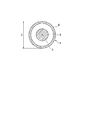
- the depth is 0 from the surface of the wire toward the center of the cross section. region up .1D 1 mm, i.e. the region of the first surface portion, and a depth of 0.25 D 1 mm to the center of the cross section, i.e. a view showing a first center.
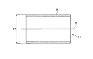
- the surface of the steel wire is directed from the surface to the center line of the cross section.
- the present inventors can manufacture a steel wire using a wire material excellent in wire drawing workability as a raw material, and then omit the softening heat treatment in the process of manufacturing a mechanical part from the steel wire.
- Component composition and structure of wire rod and steel wire that can be cold forged and have a mechanical component with a tensile strength exceeding 800 MPa without being subjected to tempering treatment such as quenching and tempering after molding as a mechanical component The relationship between and was investigated in detail.
- the non-heat treated mechanical parts targeted in the present invention are mechanical parts that have been given tensile strength by work hardening such as wire drawing or forging, omitting heat treatment such as softening annealing and quenching and tempering.
- the machine part has a reduction in area from the initial cross section of 20% or more.
- (A) The steel wire obtained by drawing a wire is increased in strength. However, a steel wire with increased strength is inferior in workability, has high deformation resistance, and is susceptible to processing cracks.
- R1 and the average particle size P S3 of bainite block satisfy the following formula 2.
- the standard deviation of the grain size of the bainite block of the steel wire is set to 8.0 ⁇ m or less.
- the bainite block which will be described in detail later, generally refers to a structural unit made of bcc iron with good orientation.
- a bainite block grain is a region where the crystal orientation of ferrite can be regarded as the same, and a boundary where the orientation difference is 15 ° or more is defined as a bainite block grain boundary from a crystal orientation map of a bcc structure.
- the present inventors investigated in detail the relationship between the component composition of a wire used as a raw material for obtaining said steel wire, and a structure
- a wire for obtaining the above steel wire not only to improve wire drawing workability, but also to obtain a steel wire structure, the volume fraction of bainite is controlled to reduce the variation in grain size of bainite blocks. It is effective to make the grain size of the bainite block in the surface layer portion fine.
- the wire drawing workability of the wire can be improved, and the above steel wire structure can be obtained.
- the ductility of a wire improves, so that the average particle diameter of a bainite block becomes fine.
- (E-1) The structure of the wire consists of bainite, ferrite and pearlite, and does not contain martensite. And [C%] The C content of (e-2) wire by mass%, when the V B1 a volume fraction of bainite by volume%, the V B1 satisfies the following formula 4, a cold steel wire It is effective for improving workability. V B1 ⁇ 75 ⁇ [C%] + 25 (Formula 4) (E-3) The average particle diameter of the bainite block of the wire is 5.0 ⁇ m to 20.0 ⁇ m, and the standard deviation of this bainite block is 15.0 ⁇ m or less.
- the present inventors examined a mechanical part obtained by cold forging the above steel wire. Specifically, in order to obtain detailed hydrogen embrittlement resistance by investigating in detail the effects of components and structure on the hydrogen embrittlement resistance of high-strength mechanical parts with a tensile strength of 800 MPa or more, particularly 1200 MPa or more. Ingredients and tissues were found. Moreover, as a result of repeating examination about the method for obtaining such a component and structure
- the mechanical component of the present invention has a cylindrical axis. Specifically, in the L cross-section is a longitudinal section parallel to its axis, the diameter of the shaft and D 3. Then, as shown in FIG. 3A, the mechanical parts, the region from the surface to a depth 0.1 D 3, that is, an average aspect ratio R2 of bainite blocks in the fourth surface portion and 1.2 or more, resistance of machine parts Hydrogen embrittlement characteristics can be improved. That is, since a bainite block that is not sufficiently elongated does not contribute much to the hydrogen embrittlement resistance, it is preferable to extend the bainite block.
- the aspect ratio R2 of the bainite block is a ratio represented by the dimension of the major axis / dimension of the minor axis of the bainite block.
- the average aspect ratio R2 of the bainite block in the fourth surface layer portion is preferably 1.5 or more.
- the average aspect ratio R2 of the bainite block in the fourth surface layer portion is preferably 2.0 or less.
- the mechanical part can obtain sufficient hydrogen embrittlement resistance without being cracked and remaining non-tempered.
- the C content of the machine part is [C%]
- the volume fraction V B3 of bainite satisfies the following formula 6 in volume%.
- the volume fraction V B3 of bainite preferably satisfies the following formula 7 in volume%.
- the wire according to the present embodiment is obtained by immersing it in a molten salt tank consisting of two tanks immediately after rolling using the residual heat at the time of hot rolling.
- the steel wire according to the present embodiment is manufactured by cold-drawing the wire according to the present embodiment. With this manufacturing method, a steel wire with a controlled volume ratio of bainite can be obtained without adding a large amount of expensive alloy elements. Therefore, this manufacturing method is the best manufacturing method that is inexpensive and can obtain excellent material properties.
- the non-heat treated machine part according to the present embodiment can be manufactured by the following series of manufacturing methods.
- the component composition is adjusted so as to control bainite, and after hot rolling, a wire rod having a desired diameter that has been wound up and cooled in two stages is used as a molten salt bath by using residual heat during hot rolling. Immerse in.
- the immersed wire is drawn under specific conditions at room temperature to obtain a steel wire having a desired diameter.
- the steel wire is formed into a machine part by cold working.
- a relatively low temperature heat treatment is performed to restore ductility. This heat treatment does not fall under “tempering”.
- a mechanical component having a tensile strength of 800 MPa to 1600 MPa which has been extremely difficult to manufacture by conventional manufacturing methods and knowledge, can be obtained at low cost.
- mechanical parts having a tensile strength of 1200 MPa to 1600 MPa can be obtained at a low cost.
- the wire for non-heat treated machine parts the steel wire for non-heat treated machine parts, and the non-heat treated machine parts according to the present embodiment will be described in detail.
- % related to the component composition means mass%.
- the chemical composition does not change during wire drawing, cold forging or forming. Therefore, the wire, the steel wire, and the machine part according to the present embodiment have the same chemical composition.
- C 0.18% to 0.65% C is contained in order to ensure the tensile strength of a predetermined steel wire and machine part.
- the C content is less than 0.18%, it is difficult to ensure a tensile strength of 800 MPa or more. Therefore, the lower limit of the C content is 0.18%.
- the upper limit of the C content is set to 0.65%.
- the C content is preferably 0.50% or less.
- the C content is preferably 0.20% or more.
- the C content is more preferably 0.21% or more, and for mechanical parts having a tensile strength of 1200 MPa to 1600 MPa, 0.54% or less. More preferably, for mechanical parts having a tensile strength of 800 MPa to 1200 MPa, 0.44% or less is more preferable.
- Si 0.05% to 1.5%
- Si functions as a deoxidizing element and has the effect of increasing the tensile strength of steel wires and machine parts by solid solution strengthening. If the Si content is less than 0.05%, these effects are insufficient. Therefore, the lower limit of the Si content is 0.05%. On the other hand, if the Si content exceeds 1.5%, these effects are saturated, and cold workability deteriorates in the steel wire, and machine cracks tend to occur in the machine parts. Therefore, the upper limit of the Si content is 1.5%. In a mechanical part having a tensile strength of 800 MPa to 1200 MPa, the Si content is preferably 0.50% or less.
- the Si content is more preferably 0.18% or more, and in the case of mechanical parts having a tensile strength of 800 MPa to 1200 MPa, 0.4% or less is more preferable, and the tensile strength is For mechanical parts of 1200 MPa to 1600 MPa, 0.90% or less is more preferable.
- Mn 0.50% to 2.0% Mn promotes bainite transformation and has the effect of increasing the tensile strength of steel wires and machine parts. If the Mn content is less than 0.50%, this effect is insufficient. Therefore, the lower limit of the Mn content is 0.50%. On the other hand, if the Mn content exceeds 2.0%, this effect is saturated and the manufacturing cost increases. Therefore, the upper limit of the Mn content is set to 2.0%. In consideration of imparting sufficient tensile strength to machine parts, the Mn content is preferably 0.60% or more, and more preferably 1.5% or less.
- P and S are impurities inevitably mixed in steel. These elements segregate at the crystal grain boundaries and degrade the hydrogen embrittlement resistance of mechanical parts. Therefore, it is better that the P content and the S content are small, and the upper limits of the P content and the S content are both 0.030%. In consideration of cold workability, the P content and the S content are preferably 0.015% or less. In addition, the minimum of P content and S content contains 0%. However, P and S are inevitably mixed in steel at least about 0.0005%.
- N 0.0050% or less N deteriorates the cold workability of the steel wire by dynamic strain aging. Therefore, it is better that the N content is small, and the upper limit of the N content is 0.0050%. Considering cold workability, the N content is preferably 0.0040% or less. Note that the lower limit of the N content includes 0%. However, N is inevitably mixed in steel at least about 0.0005%.
- O 0.01% or less O is inevitably mixed in steel and exists in the form of oxides such as Al and Ti. When the O content is large, a coarse oxide is generated, which causes fatigue failure during use as a machine part. Therefore, the upper limit of the O content is 0.01%. Note that the lower limit of the O content includes 0%. However, O is inevitably mixed in steel at least about 0.001%.
- the balance is Fe and impurities.
- the “impurities” in “the balance is Fe and impurities” refers to what is inevitably mixed from ore as a raw material, scrap, or the manufacturing environment when steel is produced industrially.
- the non-heat treated machine part wire, the non-heat treated machine part steel wire, and the non-heat treated machine part in addition to this basic component, instead of a part of the remaining Fe, Al, Ti, B, Cr, Mo, Nb and V may be contained.
- Al is 0% to 0.050% and Ti is 0% to 0.050%.
- the content of Al and Ti is arbitrary, and the Al content and Ti content may be 0%.
- these elements form AlN and TiN to reduce solid solution N and suppress dynamic strain aging.
- AlN and TiN function as pinning particles to refine crystal grains and improve cold workability.
- the upper limit of the Al content and the Ti content is preferably 0.05%.
- the Al content 0% to 0.050% If the Al content is less than 0.010%, these effects may not be obtained. Therefore, in order to reliably obtain these effects, the lower limit of the Al content is preferably 0.010%. On the other hand, when the Al content exceeds 0.050%, these effects are saturated. Therefore, the upper limit of the Al content is 0.050%. In order to obtain the effect of Al more sufficiently, the Al content is more preferably 0.015% or more, and preferably 0.045% or less.
- the Ti content 0% to 0.050% If the Ti content is less than 0.005%, these effects may not be obtained. Therefore, in order to reliably obtain these effects, the lower limit of the Ti content is preferably set to 0.005%. On the other hand, when the Ti content exceeds 0.050%, these effects are saturated. Therefore, the upper limit of the Ti content is 0.050%. In order to obtain the effect of Ti more sufficiently, the Ti content is more preferably 0.010% or more, and preferably 0.040% or less.
- the non-heat treated machine part wire, the non-heat treated machine part steel wire, and the non-heat treated machine part according to this embodiment may contain 0% to 0.0050% B.
- the B content is arbitrary, and the B content may be 0%.
- B 0% to 0.0050%
- B has an effect of promoting the bainite transformation and increasing the tensile strength of the steel wire and the machine part. If the B content is less than 0.0005%, this effect may be insufficient. Therefore, in order to reliably obtain this effect, the lower limit of the B content is preferably set to 0.0005%. On the other hand, when the B content exceeds 0.0050%, this effect is saturated. Therefore, the upper limit of the B content is set to 0.0050% or less. In order to obtain the effect of B more sufficiently, the B content is more preferably 0.0008% or more, and preferably 0.0030% or less.
- Cr 0% to 1.50%
- Mo 0% to 0.50%
- Nb 0% to 0.050%
- V 0% to 0.20%.
- the contents of Cr, Mo, Nb, and V are arbitrary, and each content may be 0%.
- Cr, Mo, Nb, and V have the effect of promoting the bainite transformation and increasing the tensile strength of the steel wire and machine parts.
- the Cr content is less than 0.01%, the above effects may not be obtained. Therefore, in order to surely obtain this effect, the lower limit of the Cr content is preferably 0.01%. On the other hand, if the Cr content exceeds 1.50%, the alloy cost increases. Therefore, the upper limit of the Cr content is 1.50%.
- the Mo content 0% to 0.50% If the Mo content is less than 0.01%, the above effects may not be obtained. Therefore, in order to reliably obtain this effect, the lower limit of the Mo content is preferably set to 0.01%. On the other hand, if the Mo content exceeds 0.50%, the alloy cost increases. Therefore, the upper limit of the Mo content is 0.50%.
- Nb 0% to 0.050% If Nb is less than 0.005%, the above effects may not be obtained. Therefore, in order to obtain this effect, the lower limit of the Nb content is preferably 0.005%. On the other hand, when the Nb content exceeds 0.050%, the alloy cost increases. Therefore, the upper limit of the Nb content is 0.050%.
- V 0% to 0.20% If V is less than 0.01%, the above effect may not be obtained. Therefore, in order to obtain this effect, the lower limit of the V content is preferably 0.01%. On the other hand, when the V content exceeds 0.20%, the alloy cost increases. Therefore, the upper limit of the Nb content is 0.20%.
- F1 obtained from the following formula 10 is preferably set to 2.0 or more.
- [C%] indicates the C content in mass%
- [Si%] indicates the Si content in mass%
- [Mn%] indicates the Mn content in mass%
- [Cr% ] Indicates Cr content in mass%
- [Mo%] indicates Mo content in mass%.
- the wire for non-tempered mechanical parts, the steel wire for non-tempered mechanical parts, and the non-tempered mechanical part according to this embodiment need to have a specific microstructure by hot-rolling the steel pieces having the above composition. There is. Next, the reason for limiting the microstructure will be described in the order of the non-heat treated machine part steel wire, the non-heat treated machine part wire, and the non-heat treated machine part according to the present embodiment.
- the steel wire for non-heat treated machine parts has the following features (i) to (p). Since the component composition (i) is already described, it is omitted in this paragraph. (I) It has the above chemical components. (J) When the C content in mass% is [C%], the structure contains 75% [C%] + 25% or more of bainite in volume%. (K) The balance is one or more of ferrite and pearlite. (L) In a cross section parallel to the longitudinal direction of the steel wire, the diameter of the steel wire is D 2 mm, and the depth is 0.1 ⁇ D 2 mm from the surface of the steel wire toward the center line of the steel wire.
- the lower limit of the volume fraction V B of the bainite of the steel wire is preferably volume%, and preferably satisfies the following formula 14.
- V B ⁇ 45 + [C%] + 50 (Expression 14)
- the volume ratio V B of the bainite is determined by the manufacturing method of the wire which will be described later, the steel wire according to the present embodiment, the wire and machine parts obtained by this steel wire by cold forging as a material of the steel wire Is constant without change.
- the steel wire according to the present embodiment can include ferrite and pearlite as the remaining structure other than bainite.
- martensite makes it easy to generate cracks during cold forging for forming machine parts. Therefore, it is preferable that the steel wire according to the present embodiment does not contain martensite.
- the steel wire according to the present embodiment has a diameter D 2 mm.
- the average aspect ratio R1 of the bainite block of the second surface layer portion measured at the L cross section which is a cross section parallel to the longitudinal direction is 1.2 or more.
- the average aspect ratio R1 of the bainite block is set to 1.2 or more.
- the average aspect ratio R1 is the ratio of the major axis to the minor axis of the bainite block grains.
- the second surface layer portion indicates a region from the surface of the steel wire to a depth of 0.1 ⁇ D 2 mm.
- the average aspect ratio R1 of the bainite block may be 2.0 or less in order to achieve both cold workability and tensile strength. Further, when the steel wire is required to have a tensile strength of 1200 MPa to 1600 MPa, in order to achieve both cold workability and tensile strength, even if the average aspect ratio R1 of the bainite block is 1.5 or more, Good.
- the steel wire according to the present embodiment has a diameter D 2 mm.
- the average particle size P S3 of the bainite block of the third surface layer portion measured in the C cross section that is a cross section perpendicular to the longitudinal direction satisfies the following formula 15 in unit ⁇ m.
- the average grain size P S3 ⁇ m of the bainite block of the third surface layer portion measured in the C cross section does not satisfy the following formula 15, that is, when it exceeds (20 / R1) ⁇ m, the cold forgeability of the steel wire deteriorates.
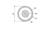
- the third surface portion as shown in FIG. 2B, the C cross-section of the steel wire, showing the area to a depth of 0.1 ⁇ D 2 mm from the surface of the steel wire.
- the diameter of the steel wire is D 2 mm, and a region having a depth of 0.1 ⁇ D 2 mm from the surface of the steel wire, that is, third
- the average particle size P S3 ⁇ m of the bainite block in the surface layer portion and the region from the depth 0.25 ⁇ D 2 mm to the center, that is, the average particle size P C3 ⁇ m of the bainite block in the third central portion are expressed by the following formula 16 Meet.
- the unit ⁇ m and P S3 showed an average particle size of bainite block in the third surface portion of the steel wire, in the unit ⁇ m and P C3, the average particle size of the bainite block in the third center of the steel wire Indicates.
- the ratio P S3 / PC 3 of the average particle diameter of the bainite block is set to 0.95 or less.
- the preferable upper limit of the average particle size ratio P S3 / PC 3 of the bainite block is 0.90.
- ⁇ (O) Standard deviation of particle size of bainite block 8.0 ⁇ m or less>
- the standard deviation of the grain size of the bainite block is 8.0 ⁇ m or less.
- the upper limit of the standard deviation of the grain size of the bainite block is set to 8.0 ⁇ m.
- the tensile strength is 800 MPa to 1600 MPa. Since this embodiment is based on obtaining a non-tempered mechanical part having a tensile strength of 800 MPa or more, a steel wire before being processed into a mechanical part is also required to have a similar tensile strength. On the other hand, it is difficult for a steel wire exceeding 1600 MPa to produce a machine part from the steel wire by cold forging. Therefore, the tensile strength is set to 800 MPa to 1600 MPa as the strength of the steel wire. A preferred tensile strength is 1200 MPa to 16000 MPa, more preferably 1240 MPa to 1560 MPa, and still more preferably 1280 to 1460 MPa.
- the wire used as the material needs to have the following features (q) to (v).
- the component composition (q) is omitted in this paragraph because it has already been described.
- (Q) It has the above chemical components.
- R When the content of C in mass% is [C%], the structure contains 75% [C%] + 25% or more of bainite in volume%.
- S The balance is one or more of ferrite and pearlite not containing martensite.
- T The average particle size of the bainite block having the above structure is 5.0 ⁇ m to 20.0 ⁇ m.
- U The standard deviation of the particle size of the bainite block is 15.0 ⁇ m or less.
- the bainite structure is controlled in the steel wire according to the present embodiment. Since the bainite volume fraction V B is not changed by wire drawing, it is necessary to control the bainite volume fraction V B at the stage of the wire to obtain the steel wire according to the present embodiment.
- the volume fraction V B of bainite is% by volume and does not satisfy the following formula 18, not only good wire drawing workability can be obtained, but also the remaining non-bainite structure becomes the starting point of fracture. Therefore, the lower limit of the volume fraction V B of the bainite of the wire material needs to satisfy the following formula 18.
- V B ⁇ 75 + [C%] + 25 (Equation 18)
- [C%] indicates the C content of the wire.
- the C content is 0.20% to 0.65%
- the lower limit of the volume fraction V B of the bainite of the wire is vol%, and the following formula 19 is preferably satisfied.
- V B ⁇ 45 + [C%] + 50 (Equation 19)
- the wire used as the material of the steel wire according to the present embodiment can include one or more ferrites and pearlites as the remaining structure other than bainite.
- martensite causes breakage during wire drawing and deteriorates wire drawing workability. Therefore, this wire does not contain martensite.
- ⁇ (T) Average particle size of bainite block 5.0 ⁇ m to 20.0 ⁇ m>
- the average particle size of the bainite block exceeds 20.0 ⁇ m in the wire, not only is cracking easy to occur in the wire drawing to the steel wire, but the grain of the bainite block in the steel wire after the wire drawing. The variation in diameter increases. Therefore, the upper limit of the average particle size of the bainite block of the wire is set to 20.0 ⁇ m.
- the lower limit of the average particle size of the bainite block of the wire is set to 5.0 ⁇ m.
- ⁇ (U) Standard deviation of grain size of bainite block 15.0 ⁇ m or less>
- the standard deviation of the grain size of the bainite block is 15.0 ⁇ m or less.
- the upper limit of the standard deviation of the grain size of the bainite block is set to 15 ⁇ m.
- the average particle size P S1 of the bainite block in the first surface layer portion and the average particle size P C1 of the bainite block in the first center portion satisfy the following Expression 20.
- P S1 / P C1 ⁇ 0.95 (Expression 20)
- P S1 is the unit ⁇ m and indicates the average particle size of the bainite block in the first surface layer portion of the wire
- P C1 is the unit ⁇ m and indicates the average particle size of the bainite block in the first center portion of the wire.
- the ratio of P S1 and P C1 exceeds 0.95, not only cracks in the wire drawing is likely to occur, deteriorating the cold workability of the steel wire. Therefore, in the wire, the average particle size ratio P S1 / PC 1 of the bainite block is set to 0.95 or less.
- the preferable upper limit of the ratio P S1 / PC 1 of the average particle diameter of the bainite block is 0.90.
- the non-heat treated machine component according to the present embodiment can be obtained.
- the non-heat treated mechanical component according to the present embodiment has a cylindrical axis and has the following features (I) to (VIII).
- the component composition (I) is omitted in this paragraph because it has already been described.
- (I) It has said chemical component.
- (II) When the content of C in mass% is [C%], the structure contains 75% [C%] + 25% or more of bainite in volume%.
- the balance is one or more of ferrite and pearlite.
- the reasons for limiting (I) to (VII) are the reasons for the above (i) to (o) of the steel wire for non-heat treated machine part according to the present embodiment.
- the reason for the limitation of each feature is the same.
- the reason for this is that in the process of manufacturing machine parts from steel wire by cold forging, the volume fraction of the components and structure does not change, the standard deviation of the grain size of bainite block, the average aspect ratio, the average grain size of the surface layer part This is because the ratio of the central part to the average particle diameter hardly changes.
- the diameter D 2 mm of the steel wire may coincide with the diameter D 3 mm of the cylinder shaft of the machine part.
- the non-tempered mechanical part may be a bolt.
- the tensile strength is 800 MPa to 1600 MPa.
- the present invention is based on obtaining a non-tempered mechanical part having a tensile strength of 800 MPa or more. If the strength as a part is less than 800 MPa in tensile strength, it is not necessary to apply the present invention. On the other hand, hydrogen embrittlement characteristics deteriorate in parts exceeding 1600 MPa. Therefore, the tensile strength is set to 800 MPa to 1600 MPa as the component strength.
- a preferred tensile strength is 1200 MPa to 16000 MPa, more preferably 1240 MPa to 1560 MPa, and still more preferably 1280 to 1460 MPa.
- the volume fraction of bainite is obtained by, for example, photographing a C cross section of a wire, that is, a cross section perpendicular to the longitudinal direction of the wire at a magnification of 1000 times with a scanning electron microscope and analyzing the image.
- the vicinity of the surface layer (surface) of the wire rod (first surface layer portion), 1 / 4D 1 portion (from the surface of the wire rod to the center of the wire rod, that is, 1/1 of the diameter D 1 of the wire rod in the depth direction). 4 portions) and 1 / 2D 1 portion (first central portion: central portion of the wire) are each photographed in an area of 125 ⁇ m ⁇ 95 ⁇ m.
- the area ratio of bainite is obtained by measuring the area of each bainite in the region and dividing the total value by the observation region.
- the area ratio of a non-bainite structure is obtained by subtracting the area ratio of bainite from 100%.
- the area ratio of the tissue included in the observation plane, that is, the C cross section is equal to the volume ratio of the tissue
- the area ratio obtained by image analysis is the volume ratio of the tissue.
- the volume fraction of the bainite of a steel wire and a machine part can be measured similarly.
- the bainite block means the following.
- a boundary where the orientation difference is 15 ° or more is defined as a bainite block grain boundary.
- grain obtained by the below-mentioned method is defined as the grain diameter of a bainite block.
- the particle size of the bainite block can be measured using, for example, an EBSD (Electron Back Scatter Diffraction Patterns) apparatus.
- EBSD Electro Back Scatter Diffraction Patterns
- the first central portion is a region from a position that is a quarter of a diameter D 1 mm away from the surface of the wire in the center direction to the center.
- the region of the wire rod having a depth of 1 / 4D 1 mm to 1 / 2D 1 mm is the first central portion. Then, in each of the first surface layer portion and the first center portion, a region of 275 ⁇ m ⁇ 165 ⁇ m is measured, the volume of each bainite block is calculated from the equivalent circle diameter of the bainite block in the field of view, and the volume average is averaged Defined as particle size. And the average particle diameter of a bainite block is an average particle diameter of a 1st surface layer part and a 1st center part. In addition, it can measure by the same method also in a steel wire and a machine part.
- the standard deviation of the grain size of the bainite block can be determined by measuring one location at 45 ° intervals in the first surface layer portion and the first center portion described above, and by distribution of the measured values. In addition, it is computable with the same method also about a steel wire and a machine part.
- the average aspect ratio of the bainite block can be measured by the following method. Specifically, as shown in FIG. 2A, in the L cross section that is a cross section parallel to the longitudinal direction of the steel wire, the range from the surface to a depth of 0.1 ⁇ D 2 mm toward the center line of the cross section, That is, a region of 275 ⁇ m ⁇ 165 ⁇ m is measured using EBSD at the second surface layer portion.
- the ratio of the average particle size P S1 of the bainite block in the first surface layer portion of the wire to the average particle size P C1 of the bainite block in the center portion is obtained by the following method. As shown in FIG. 1, the C cross-section in the longitudinal direction and the cross section perpendicular wire, when the diameter of the wire and D 1 mm, the area of depth 0.1 ⁇ D 1 mm from the surface first surface portion And Further, as shown in FIG.
- the wire, the steel wire, and the machine part according to the present embodiment can be manufactured as follows.
- the manufacturing method of the wire, the steel wire, and the machine part described below is an example for obtaining the wire, the steel wire, and the machine part according to the present embodiment, and is not limited by the following procedure and method. Any method can be adopted as long as the configuration of the present invention can be realized.
- the volume fraction of bainite, the average particle size of the bainite block, the standard deviation of the particle size of the bainite block, the average aspect ratio of the bainite block of the surface layer portion, the surface layer portion In order to ensure that the average particle size of the bainite block and the ratio of the average particle size of the bainite block between the surface layer portion and the central portion can satisfy the above-mentioned conditions, the chemical composition of each steel, each step, and each What is necessary is just to set the conditions in a process. Moreover, manufacturing conditions can be set according to the tensile strength required for machine parts.
- the steel piece which consists of a predetermined component composition is heated.
- the heated steel slab is hot-rolled and wound up in a ring shape at over 900 ° C.
- two-stage cooling including primary cooling and secondary cooling as described later is performed, and then a constant temperature holding (constant temperature transformation treatment) is performed to obtain a wire.
- primary cooling the temperature from the winding end temperature to 600 ° C. is cooled at a primary cooling rate of 20 ° C./second to 100 ° C./second, and further from 600 ° C. to 500 ° C. as 20 ° C. Cool at a secondary cooling rate of less than / sec.
- the steel wire for non-heat treated machine parts according to the present embodiment having the above microstructure can be manufactured by performing constant temperature holding (constant temperature transformation treatment) and then performing wire drawing. .
- the coiling temperature affects the bainite structure after transformation.
- the coiling temperature is 900 ° C. or less, the standard deviation of the grain size of the bainite block becomes large, and there may be a case where cold cracking of the steel wire or work cracking occurs in the machine part. Therefore, the coiling temperature is over 900 ° C.
- the two-stage cooling is performed by the following method. Utilizing the residual heat at the time of hot rolling, the wire is immersed in a molten salt bath to cause a constant temperature bainite transformation. That is, immediately after winding, the wire is immersed in a molten salt bath 1 at 350 ° C. to 500 ° C., cooled to 600 ° C., and then cooled to 500 ° C. to perform two-stage cooling. Thereafter, the substrate is immersed in a molten salt bath 2 at 350 ° C. to 600 ° C. that is continuous with the molten salt bath 1 and kept at a constant temperature.
- the immersion time in the molten salt tank 1 is 5 seconds to 150 seconds, and the immersion time in the molten salt tank 2 is 5 seconds to 150 seconds.
- the total immersion time in the molten salt tank 1 and the molten salt tank 2 is 40 seconds or longer.
- the immersion time in the molten salt bath 1 is 25 seconds to 150 seconds, and the immersion time in the molten salt bath 2 is 25 seconds to 150 seconds.
- the total immersion time of the molten salt tank 1 and the molten salt tank 2 is preferably 60 seconds or more.
- the bainite produced by the isothermal transformation treatment has less variation in the grain size of the bainite block compared to the bainite produced by the continuous cooling treatment.
- the immersion time in the molten salt tank is 5 to 150 seconds in any tank from the viewpoint of sufficient temperature maintenance and productivity of the wire.
- the cooling after being kept in the molten salt tank for a predetermined time may be water cooling or standing cooling.
- the molten salt tank is excellent.
- the area reduction rate is 10% to 80%.
- the area reduction ratio of the wire drawing is less than 10%, the work hardening is insufficient and the tensile strength is insufficient.
- the area reduction rate exceeds 80%, work cracks are likely to occur during cold forging in which a machine part is manufactured from a steel wire.
- the area reduction rate is preferably 20% to 90% in the wire drawing.
- the area reduction rate of wire drawing is less than 20%, the hydrogen embrittlement resistance of machine parts deteriorates.
- the area reduction rate exceeds 90%, it becomes easier to generate work cracks during cold forging in which a machine part is manufactured from a steel wire.
- the area reduction rate of the wire drawing is preferably 30% to 86%.
- the steel wire thus obtained is used to form a final machine part.
- the steel wire obtained in this way is cold forged, that is, cold worked to obtain a non-tempered mechanical part having a tensile strength of 800 MPa to 1600 MPa.
- the tensile strength is set to 800 MPa or more.
- the pressure is 1200 MPa or more, the improvement in hydrogen embrittlement resistance is remarkable.
- the tensile strength required for the machine part exceeds 1600 MPa, it is difficult to manufacture the machine part according to the present embodiment by cold forging, and the hydrogen embrittlement resistance of the machine part is deteriorated. To do. Therefore, the tensile strength of the machine part is set to 800 MPa to 1600 MPa.
- the mechanical component according to the present embodiment has high strength as it is as a mechanical component.
- the machine parts are cooled to 200 ° C. to 600 ° C. for 10 minutes after cold forging into the part shape. It may be held for 5 hours and then cooled. This heat treatment does not correspond to the heat treatment for tempering.
- Table 1 shows the component composition.
- the underline in the table indicates that it is outside the scope of the present invention.
- the C content is [C%]
- the Si content is [Si%]
- the Mn content is [Mn%]
- the Cr content is [Cr%].
- F1 was calculated by the following formula G, where the Mo content was [Mo%]. The obtained F1 is shown in Table 1.
- F1 0.6 ⁇ [C%] ⁇ 0.1 ⁇ [Si%] + 1.4 ⁇ [Mn%] + 1.3 ⁇ [Cr%] + 3.7 ⁇ [Mo%] (G)
- Table 2-1 shows the coiling temperature after hot rolling, the temperature and holding time of the molten salt bath 1, the primary cooling rate from the coiling temperature to 600 ° C, the secondary cooling rate from 600 ° C to 500 ° C, And the constant temperature holding temperature and the constant temperature holding time in the molten salt tank 2 are shown.
- the wire that had been subjected to the isothermal transformation treatment was subjected to wire drawing at the same area reduction as shown in Table 2-1, to obtain a steel wire.
- Table 2-2-1 shows the wire structure
- Table 2-2-2 shows the steel wire structure.
- the volume fraction of bainite in a wire corresponds with the volume fraction of bainite in a steel wire.
- V B unit: volume% of bainite
- the underline does not satisfy the following formula H.
- F represents ferrite
- P represents pearlite
- M represents martensite.
- the volume fraction of bainite was determined by photographing a C cross section of the wire, that is, a cross section perpendicular to the longitudinal direction of the wire at a magnification of 1000 times with a scanning electron microscope and analyzing the image.
- the average particle size of the bainite block of the wire in Table 2-2-1 was measured by the following method.
- the boundary where the orientation difference is 15 ° or more was defined as a bainite block grain boundary.
- the first central portion is a region from a position that is a quarter of a diameter D 1 mm away from the surface of the wire in the center direction to the center.
- each bainite block is calculated from the equivalent circle diameter of the bainite block in the field of view. Defined. And the average particle diameter of the bainite block was made into the average particle diameter of a 1st surface layer part and a 1st center part. In Table 2-2-1, bainite blocks whose average particle diameter is not in the range of 5.0 ⁇ m to 20.0 ⁇ m are underlined.
- the standard deviation of the grain size of the bainite block of the wire in Table 2-2-1 and the standard deviation of the grain size of the bainite block of the steel wire in Table 2-2-2 were measured by the following methods.
- the standard deviation of the grain size of the bainite block in the wire was obtained from the respective distributions of the measured value of the first surface layer part and the measured value of the first central part. In the case of a steel wire, it was determined from the distribution of the measured values of the third surface layer portion and the third center portion.
- Table 2-2-1 the bainite block with a standard deviation exceeding 15.0 ⁇ m is underlined
- Table 2-2-2 the bainite block with a standard deviation exceeding 8.0 ⁇ m is underlined. did.
- Table 2-2-1 shows the average particle size P S1 of the bainite block in the first surface layer portion of the wire and the average particle size P C1 of the bainite block in the first central portion.
- Table 2-2-2 shows the average particle size P C3 of bainite blocks in average particle size P S3 and the third center of bainite block in the third surface portion of the steel wire.
- the average particle diameters P S1 , P C1 , P S3 and P C3 (unit: ⁇ m) of the bainite block in the first surface layer portion and the first center portion of the wire rod and in the third surface layer portion and the third center portion of the steel wire are: It measured by the following method.
- each region of 275 ⁇ m ⁇ 165 ⁇ m was measured using EBSD, the volume of each bainite block was calculated from the equivalent circle diameter of the bainite block in the field of view, and the volume average was obtained as the average particle diameter.
- the 1st surface layer part and 1st center part of a wire, and the 3rd surface layer part and 3rd center part of a steel wire it is as above-mentioned.
- the ratio of the average particle size P S1 of the bainite block of the first surface layer portion to the average particle size P C1 of the bainite block of the first center portion does not satisfy the following formula I. It was attached.
- the average aspect ratio R1 of the bainite block in the second surface layer portion of the steel wire was measured by the following method.
- the L cross section which is a cross section parallel to the longitudinal direction of the steel wire, in the range from the surface to a depth of 0.1 ⁇ D 2 mm toward the center line of the cross section, that is, in the second surface layer portion, 275 ⁇ m ⁇ 165 ⁇ m Area was measured using EBSD.
- the second surface layer portion having an average aspect ratio R1 of less than 1.2 is underlined. Further, in the steel wire, the relationship between the average aspect ratio R1 of the second surface portion and the average particle size P S3 of bainite block of the third surface layer portion, is not satisfied the following formula K, underlined. P S3 ⁇ 20 / R1 (K)
- Table 2-3 shows the wire drawing workability of the wire.
- the wire drawing workability of the wire was judged to be “poor” when the wire breakage occurred even once during the drawing from the wire to the steel wire.
- Table 2-3 shows the tensile strength and cold workability of the steel wire.
- the tensile strength was evaluated by performing a tensile test based on the test method of JIS Z 2241 using a 9A test piece of JIS Z 2201. Cold workability was evaluated based on deformation resistance and critical compressibility. First, the steel wire after wire drawing was machined to prepare a sample of ⁇ 5.0 mm ⁇ 7.5 mm. And the end surface was restrained and compressed using the metal mold
- the maximum stress (deformation resistance) when processing at a compression rate of 57.3% corresponding to a strain of 1.0 was obtained, and the maximum compression rate (limit compression rate) at which cracking did not occur was evaluated.
- the deformation resistance was determined to be “good” when the maximum stress when processed at a compression rate of 57.3% was 1100 MPa or less. Further, when the maximum compression rate at which no cracks occurred was 70% or more, the critical compression rate was determined as “good”.
- the deformation resistance was judged as “good” when the maximum stress when processed at a compression rate of 57.3% was 1200 MPa or less. Further, when the maximum compression rate at which no cracks occurred was 60% or more, the critical compression rate was determined as “good”. In addition, it is a comparative example about the wire in the case where the wire rod is drawn and a steel wire having a target structure cannot be obtained.
- Table 3-1 shows the heat treatment temperature and holding time of the heat treatment performed after cold forging of the steel wire.
- machine part no. Nos. 1001 to 1018 and 1042 are examples when the mechanical parts are required to have a tensile strength of 800 MPa to 1200 MPa.
- Reference numerals 1019 to 1036 are examples when the mechanical parts are required to have a tensile strength of 1200 to 1600 MPa.
- Table 3-2 shows the tensile strength and hydrogen embrittlement resistance of machine parts.
- the tensile strength was evaluated by conducting a tensile test based on the test method of JIS Z 2241 using a 9A test piece of JIS Z 2201 as in the case of the steel wire.
- the hydrogen embrittlement resistance was evaluated by the following method. First, a steel wire is processed into a bolt, and in the case of a bolt with a tensile strength of 800 to 1200 MPa, 2.0 ppm of diffusible hydrogen is contained in the sample by electric field hydrogen charging. The sample contained 5 ppm of diffusible hydrogen. Thereafter, Cd plating was applied so that hydrogen was not released from the sample into the atmosphere during the test.
- Steel wire No. 105, 113 and 120 had a short total molten salt tank retention time. As a result, martensite was generated as the balance other than bainite, and the steel wire could not be manufactured due to the disconnection during wire drawing.
- Steel wire No. Since No. 139 has a large Si content, martensite was generated, and a steel wire could not be produced due to a disconnection during wire drawing.
- Steel wire No. 102, 110, 111, 114, 115, 118, 124, 125, 127, 128, 136, and 142 when the coiling temperature is low or / and cooling or isothermal transformation treatment is not sufficient, either of the above One or more of the properties could not be satisfied. As a result, although good wire drawing workability as a wire was obtained, good cold workability as a steel wire could not be obtained.
- Steel wire No. 102, 110, 111, 114, 115, 118, 124, 125, 127, 128, 136 and 142 machine part Nos. Manufactured by cold forging.
- the present invention it is possible to inexpensively provide a wire rod excellent in wire drawing workability, a steel wire excellent in cold workability, and a high-strength mechanical component having a tensile strength of 800 MPa to 1600 MPa. it can.
- This high-strength machine part can contribute to weight reduction and size reduction of automobiles, various industrial machines, and construction members. Therefore, the present invention has high applicability in automobiles, various industrial machines, and the construction industry, and the industrial contribution is extremely remarkable.
Landscapes
- Chemical & Material Sciences (AREA)
- Engineering & Computer Science (AREA)
- Materials Engineering (AREA)
- Mechanical Engineering (AREA)
- Metallurgy (AREA)
- Organic Chemistry (AREA)
- Physics & Mathematics (AREA)
- Thermal Sciences (AREA)
- Crystallography & Structural Chemistry (AREA)
- Manufacturing & Machinery (AREA)
- Heat Treatment Of Steel (AREA)
- Heat Treatment Of Articles (AREA)
Abstract
Description
本発明は、この非調質機械部品、これを製造するための鋼線、及び、この鋼線を製造するための線材に関する。
なお、本発明で対象とする非調質機械部品には、自動車用や建築用のボルト等も含まれる。
これ以降、非調質機械部品用線材を単に線材と、非調質機械部品用鋼線を単に鋼線と、及び、非調質機械部品を単に機械部品と称する場合がある。
本願は、2015年1月27日に、日本に出願された特願2015-013385号及び2015年2月19日、日本に出願された特願2015-030891号に基づき優先権を主張し、この内容をここに援用する。
この水素脆化現象とは、線材や鋼線に侵入した水素の影響により、本来予想される応力より小さい応力にて機械部品が破壊する現象である。
この水素脆化現象は種々の形態で現れる。
例えば、自動車及び建築物等に用いられるボルトにおいては、遅れ破壊が生じることがある。
ここで、遅れ破壊とは、ボルトなどの場合には、締結してから暫く時間が経った後に、突然ボルトに破壊が生じる現象である。
高強度機械部品は、機械構造用炭素鋼にMn、Cr、MoまたはBなどの合金元素を添加した合金鋼や特殊鋼の鋼材を用いて製造されている。
具体的には、まず、この合金鋼の鋼材を熱間圧延し、その後球状化焼鈍を行い、軟質化させる。次に、軟質化させた鋼材を、冷間鍛造や転造で所定の形状に成形する。そして、成形後に、焼入れ焼戻し処理を行って、引張強さを付与する。
また、高強度機械部品の一例であるボルトに関しては、耐遅れ破壊特性を向上させる技術の一つとして、伸線加工したパーライトを用いる技術が知られている。
さらに、部品形状に成形する前の軟質化焼鈍や、成形後の焼入れ焼戻し処理を必要とするので、製造コストが上昇する。
また、これらの線材に伸線加工を施して、所定の引張強さを付与する技術が知られている。
そして、この技術はボルト等に利用され、この技術を用いて製造したボルトは非調質ボルトと呼ばれている。
また、組織が不均一となり、冷間鍛造性が劣化する場合がある。
しかしながら、この鋼は、ラメラ状の粗大なセメンタイトを含むため、従来、ボルト等の機械部品に用いている機械構造用炭素鋼や機械構造用合金鋼と比較して、冷間鍛造性が劣る。
さらに、従来技術では、これを製造するための鋼線及び線材が得ることができない。
そのため、引張強さが800MPa以上、特に、1200MPa以上の非調質の高強度の機械部品において、良好な耐水素脆化特性を得ることは困難である。
(1)本発明の第一の態様に係る非調質機械部品用鋼線は、鋼線であって、化学成分として、質量%で、C:0.18%~0.65%、Si:0.05%~1.5%、Mn:0.50%~2.0%、Cr:0%~1.50%、Mo:0%~0.50%、Ti:0%~0.050%、Al:0%~0.050%、B:0%~0.0050%、Nb:0%~0.050%、V:0%~0.20%を含有し、P:0.030%以下、S:0.030%以下、N:0.0050%以下、O:0.01%以下に制限され、残部がFe及び不純物であり;質量%での前記Cの含有量を[C%]とするとき、組織が、体積%で75×[C%]+25以上のベイナイトを含み、残部が、フェライト及びパーライトの1つ以上であり;前記鋼線の長手方向に平行な断面において、前記鋼線の直径をD2mmとし、前記鋼線の表面から前記断面の中心線に向かって深さ0.1×D2mmまでの領域を前記鋼線の第2表層部とし、前記鋼線の第2表層部におけるベイナイトブロックの平均アスペクト比をR1とするとき、前記R1が1.2以上であり;前記鋼線の長手方向に垂直な断面において、前記鋼線の直径をD2mmとし、前記鋼線の表面から前記断面の中心に向かって深さ0.1×D2mmまでの領域を前記鋼線の第3表層部、深さ0.25×D2mmから前記断面の中心までの領域を前記鋼線の第3中心部とし、前記鋼線の第3表層部における前記ベイナイトブロックの平均粒径をPS3μm、前記鋼線の第3中心部における前記ベイナイトブロックの平均粒径をPC3μmとするとき、前記PS3が下記式(C)を満たしてかつ、前記PS3と前記PC3とが下記式(D)を満たし;前記組織における前記ベイナイトブロックの粒径の標準偏差が8.0μm以下であり;引張強さが800MPa~1600MPaである。
PS3≦20/R1・・・(C)
PS3/PC3≦0.95・・・(D)
(2)上記(1)に記載の非調質機械部品用鋼線では、前記化学成分として、質量%で、C:0.18%~0.50%、Si:0.05%~0.50%を含有してもよい。
(3)上記(1)に記載の非調質機械部品用鋼線では、前記化学成分として、質量%で、C:0.20%~0.65%を含有してもよく、質量%で前記Cの含有量を[C%]とするとき、前記組織が、体積%で45×[C%]+50以上の前記ベイナイトを含んでもよい。
(4)上記(1)~(3)のいずれか1つに記載の非調質機械部品用鋼線では、前記化学成分として、質量%で、B:0.0005%未満を含有し、質量%で、前記Cの含有量を[C%]とし、前記Siの含有量を[Si%]とし、前記Mnの含有量を[Mn%]とし、前記Crの含有量を[Cr%]とし、前記Moの含有量を[Mo%]とするとき、下記式(B)で求められるF1が2.0以上でもよい。
F1=0.6×[C%]-0.1×[Si%]+1.4×[Mn%]+1.3×[Cr%]+3.7×[Mo%]・・・(B)
(5)上記(1)に記載の非調質機械部品用鋼線では、前記R1が2.0以下でもよい。
(6)上記(1)に記載の非調質機械部品用鋼線では、前記組織が、体積%で45×[C%]+50以上の前記ベイナイトを含んでもよい。
(7)本発明の第二の態様に係る非調質機械部品用線材は、上記(1)~(6)いずれか1つに記載の非調質機械部品用鋼線を得るための線材であって、化学成分として、質量%で、C:0.18%~0.65%、Si:0.05%~1.5%、Mn:0.50%~2.0%、Cr:0%~1.50%、Mo:0%~0.50%、Ti:0%~0.050%、Al:0%~0.050%、B:0%~0.0050%、Nb:0%~0.050%、V:0%~0.20%を含有し、P:0.030%以下、S:0.030%以下、N:0.0050%以下、O:0.01%以下に制限され、残部がFe及び不純物であり;質量%での前記Cの含有量を[C%]とするとき、組織が、体積%で75×[C%]+25以上のベイナイトを含み、残部が、マルテンサイトを含まないフェライト及びパーライトの1つ以上であり;前記組織のベイナイトブロックの平均粒径が5.0μm~20.0μmであり、前記ベイナイトブロックの粒径の標準偏差が15.0μm以下であり;前記線材の長手方向に垂直な断面において、前記線材の直径をD1mmとし、前記線材の表面から前記断面の中心に向かって深さ0.1×D1mmまでの領域を前記線材の第1表層部、深さ0.25×D1mmから前記断面の中心までの領域を前記線材の第1中心部としたとき、前記第1表層部での前記ベイナイトブロックの平均粒径をPS1μmと、前記第1中心部での前記ベイナイトブロックの平均粒径をPC1μmとが、下記式(A)を満たす。
PS1/PC1≦0.95・・・(A)
(8)上記(7)に記載の非調質機械部品用線材では、前記化学成分として、質量%で、C:0.18%~0.50%、Si:0.05%~0.50%を含有してもよい。
(9)上記(7)に記載の非調質機械部品用線材では、前記化学成分として、質量%で、C:0.20%~0.65%を含有してもよく、質量%で前記Cの含有量を[C%]とするとき、前記組織が、体積%で45×[C%]+50以上の前記ベイナイトを含んでもよい。
(10)本発明の第三の態様に係る非調質機械部品は、円柱の軸を有する非調質機械部品であって、化学成分として、質量%で、C:0.18%~0.65%、Si:0.05%~1.5%、Mn:0.50%~2.0%、Cr:0%~1.50%、Mo:0%~0.50%、Ti:0%~0.050%、Al:0%~0.050%、B:0%~0.0050%、Nb:0%~0.050%、V:0%~0.20%を含有し、P:0.030%以下、S:0.030%以下、N:0.0050%以下、O:0.01%以下に制限され、残部がFe及び不純物であり;質量%での前記Cの含有量を[C%]とするとき、組織が、体積%で75×[C%]+25%以上のベイナイトを含み、残部が、フェライト及びパーライトの1つ以上であり;前記軸の長手方向に平行な断面において、前記軸の直径をD3mmとし、前記軸の表面から前記断面の中心線に向かって深さ0.1×D3mmまでの領域を前記機械部品の第4表層部とし、前記機械部品の第4表層部におけるベイナイトブロックの平均アスペクト比をR2とするとき、前記R2が1.2以上であり;前記軸の長手方向に垂直な断面において、前記軸の直径をD3mmとし、前記軸の表面から前記断面の中心に向かって深さ0.1×D3mmまでの領域を前記機械部品の第5表層部、深さ0.25×D3mmから前記断面の中心までの領域を前記機械部品の第5中心部とし、前記機械部品の第5表層部における前記ベイナイトブロックの平均粒径をPS5μm、前記機械部品の第5中心部における前記ベイナイトブロックの平均粒径をPC5μmとするとき、前記PS5が下記式(E)を満たしてかつ、前記PS5と前記PC5とが下記式(F)を満たし;前記組織における前記ベイナイトブロックの粒径の標準偏差が8.0μm以下であり、引張強さが800MPa~1600MPaである。
PS5≦20/R2・・・(E)
PS5/PC5≦0.95・・・(F)
(11)上記(10)に記載の非調質機械部品は、上記(1)~(6)のいずれか1つに記載の鋼線を冷間加工して得られる非調質機械部品であってもよい。
(12)上記(10)または(11)に記載の非調質機械部品では、前記R2が1.5以上であり、前記引張強さが1200MPa~1600MPaであってもよい。
(13)上記(10)または(11)に記載の非調質機械部品では、前記D2と前記D3とが等しくてもよい。
(14)上記(10)~(13)のいずれか1つに記載の非調質機械部品は、ボルトであってもよい。
また、本発明は、自動車、各種産業機械、及び、建設用部材の軽量化や小型化に寄与することができ、産業上の貢献が、極めて顕著である。
また、本発明で対象とする非調質機械部品とは、軟質化焼鈍や焼入れ焼戻し処理などの熱処理を省略して、伸線や鍛造などの加工硬化により引張強さを付与した機械部品であり、ここでは、初期断面からの減面率が20%以上である機械部品とする。
(b)高強度鋼線の加工性を向上させるためには、鋼線のベイナイトの体積率を制御すること、ベイナイトブロックの粒径のばらつきを小さくすること、表層部のベイナイトブロックの粒径を微細にすることが有効である。
(c)鋼線のC含有量を質量%で[C%]とし、ベイナイトの体積率を体積%でVB2とするとき、VB2が下記式1を満たすことは、鋼線の冷間加工性を高めることに有効である。
VB2≧75×[C%]+25・・・(式1)
(d)下記(d-1)~(d-4)を全て満たすことによって、鋼線の冷間加工性を著しく高めることができる。
(d-1)鋼線の長手方向に平行な断面において、鋼線の直径をD2mmとし、鋼線の表面から鋼線の中心線に向かって深さ0.1D2mmまでの領域、すなわち、鋼線の第2表層部において、ベイナイトブロックの平均アスペクト比をR1とする。このR1を1.2以上とする。
(d-2)鋼線の長手方向に垂直な断面において、鋼線の表面から前記断面の中心に向かって深さ0.1D2mmまでの領域、すなわち、鋼線の第3表層部において、R1とベイナイトブロックの平均粒径PS3とが、下記式2を満たす。
PS3≦20/R1・・・(式2)
(d-3)鋼線のベイナイトブロックの粒径の標準偏差を8.0μm以下にする。
(d-4)鋼線の長手方向に垂直な断面において、鋼線の直径をD2mmとしたとき、深さ0.25D2mmから前記断面の中心までの領域、すなわち第3中心部において、ベイナイトブロックの平均粒径をPC3とするとき、このPC3と上記第3表層部のベイナイトブロックの平均粒径PS3とが、下記式3を満たす。
PS3/PC3≦0.95・・・(式3)
ここで、ベイナイトブロックとは、詳細は後述するが、一般的には、方位性が整ったbcc鉄からなる組織単位をいう。
ベイナイトブロック粒とは、フェライトの結晶方位が同じと見なせる領域であり、bcc構造の結晶方位マップから、方位差が15°以上となる境界を、ベイナイトブロック粒界とする。
上記の鋼線を得るための線材として、伸線加工性を高めるためだけでなく、鋼線の組織を得るためには、ベイナイトの体積率を制御し、ベイナイトブロックの粒径のばらつきを小さくし、表層部のベイナイトブロックの粒径を微細にすることが有効である。具体的には、下記(e-1)~(e-4)を満たすことによって、線材の伸線加工性を高めて、上記の鋼線の組織を得ることが出来る。
また、ベイナイトブロックの平均粒径が微細になるほど、線材の延性が向上する。
(e-1)線材の組織は、ベイナイト、フェライト及びパーライトからなり、マルテンサイトは含まない。
(e-2)線材のC含有量を質量%で[C%]とし、ベイナイトの体積率を体積%でVB1とするとき、VB1が下記式4を満たすことは、鋼線の冷間加工性を高めることに有効である。
VB1≧75×[C%]+25・・・(式4)
(e-3)線材のベイナイトブロックの平均粒径は5.0μm~20.0μmであり、このベイナイトブロックの標準偏差は15.0μm以下である。
(e-4)線材の長手方向に垂直な断面において、線材の直径をD1mmとし、線材の表面から前記断面の中心に向かって深さ0.1D1mmまでの領域を、線材の第1表層部とする。また、深さ0.25D1mmから前記断面の中心までの領域を第1中心部とする。そして、第1表層部のベイナイトブロックの平均粒径をPS1とし、第1中心部のベイナイトブロックの平均粒径をPC1とするとき、このPS1とPC1とが、下記式5を満たす。
PS1/PC1≦0.95・・・(式5)
また、このような成分及び組織を得るための方法について、冶金的知見に基づいて検討を重ねた結果、以下の事項が明らかになった。
本発明の機械部品は、円柱の軸を有する。
具体的には、その軸の長手方向と平行な断面であるL断面において、軸の直径をD3とする。
そして、図3Aに示すように、機械部品において、表面から深さ0.1D3までの領域、すなわち第4表層部におけるベイナイトブロックの平均アスペクト比R2を1.2以上とすると、機械部品の耐水素脆化特性を向上させることができる。
即ち、十分に伸長化していないベイナイトブロックは耐水素脆化特性にあまり寄与しないため、ベイナイトブロックを伸長化させることが好ましい。
ここで、ベイナイトブロックのアスペクト比R2とは、ベイナイトブロックの長軸の寸法/短軸の寸法で示される比率である。
特に、機械部品において、1200MPa~1600MPaの引張強さが求められる場合には、第4表層部におけるベイナイトブロックの平均アスペクト比R2を1.5以上とすることが好ましい。
一方、機械部品において、800MPa~1200MPaの引張強さが求められる場合には、第4表層部におけるベイナイトブロックの平均アスペクト比R2を2.0以下とすることが好ましい。
(f)機械部品のC含有量を[C%]とするとき、ベイナイトの体積率VB3は、体積%で、下記式6を満たす。
VB3≧75×[C%]+25・・・(式6)
特に、機械部品において、1200MPa~1600MPaの引張強さが求められる場合には、ベイナイトの体積率VB3は、体積%で、下記式7を満たすことが好ましい。
VB3≧45×[C%]+50・・・(式7)
(g)そして、上記のベイナイトブロックの平均アスペクト比をR2としたとき、R2が1.2以上であり、機械部品の軸の長手方向と垂直な断面であるC断面の第5表層部において、ベイナイトブロックの平均粒径PS5が、単位μmで、下記式8を満たす。
PS5≦20/R2・・・(式8)
(h)さらに、ベイナイトブロックの粒径の標準偏差を8.0μm以下にするとともに、かつ、機械部品の第5表層部と第5中心部のベイナイトブロックの平均粒径PS5及びPC5とが、下記式9を満たす。
PS5/PC5≦0.95・・・(式9)
すなわち、本実施形態に係る鋼線を用いれば、軟質化熱処理を省略しても冷間鍛造が可能である。
つまり、本実施形態に係る鋼線を用いれば、鋼線の球状化熱処理(軟質化熱処理)の軟質化焼鈍費用と、機械部品を製造する際、鋼線を成形した後の焼入れ焼戻し処理にかかる費用を削減できるので、コスト面等において、有利である。
まず、ベイナイトを制御すべく成分組成を調整し、熱間圧延を経て、巻き取り及び2段階冷却を行った所望の直径を有する線材を、熱間圧延時の残熱を利用して溶融塩槽に浸漬する。
次に、浸漬した線材を、室温で特定の条件にて伸線加工して、所望の直径を有する鋼線を得る。
そして、鋼線を冷間加工によって機械部品に成形する。
成形後、延性を回復させるための比較的低温の熱処理を行う。この熱処理は、「調質」には該当ない。
特に、引張強さ1200MPa~1600MPaの機械部品を安価に得ることができる。
まず、本実施形態における、線材、鋼線、非調質機械部品の化学成分の組成の限定理由についてより詳細に説明する。
以下、成分組成に係る%は、質量%を意味する。
伸線加工、冷間鍛造や成形などの加工では、化学成分は変化しない。そのため、本実施形態に係る線材、鋼線及び機械部品は、同一の化学組成を有する。
Cは、所定の鋼線及び機械部品の引張強さを確保するために含有させる。
C含有量が、0.18%未満では、800MPa以上の引張強さを確保することが困難である。
したがって、C含有量の下限を0.18%とする。
一方、C含有量が、0.65%を超えると、鋼線の冷間鍛造性が劣化する。
したがって、C含有量の上限を0.65%とする。
一方、引張強さが1200MPa~1600MPaの機械部品では、C含有量は、0.20%以上であることが好ましい。
鋼線において、高強度と冷間鍛造性とを両立するためには、C含有量は0.21%以上がより好ましく、引張強さが1200MPa~1600MPaの機械部品では、0.54%以下がより好ましく、引張強さが800MPa~1200MPaの機械部品では、0.44%以下がより好ましい。
Siは、脱酸元素として機能するとともに、固溶強化により鋼線及び機械部品の引張強さを高める効果を有する。
Si含有量が0.05%未満では、これらの効果が不十分である。
したがって、Si含有量の下限を0.05%とする。
一方、Si含有量が1.5%を超えると、これらの効果が飽和するとともに、鋼線において冷間加工性が劣化し、機械部品において加工割れが発生しやすくなる。
したがって、Si含有量の上限を1.5%とする。
引張強さが800MPa~1200MPaの機械部品では、Si含有量は、0.50%以下であることが好ましい。
Siの効果をより十分に得るためには、Si含有量は0.18%以上がより好ましく、引張強さが800MPa~1200MPaの機械部品では、0.4%以下がより好ましく、引張強さが1200MPa~1600MPaの機械部品では、0.90%以下がより好ましい。
Mnは、ベイナイト変態を促進し、鋼線及び機械部品の引張強さを高める効果を有する。
Mn含有量が0.50%未満では、この効果が不十分である。
したがって、Mn含有量の下限を0.50%とする。
一方、Mn含有量が2.0%を超えると、この効果が飽和するとともに製造コストが増加する。
したがって、Mn含有量の上限を2.0%とする。
機械部品に十分な引張強さ付与することを考慮すると、Mn含有量は、0.60%以上が好ましく、1.5%以下が好ましい。
S:0.030%以下
PとSとは、不可避的に鋼に混入する不純物である。
これらの元素は、結晶粒界に偏析して、機械部品の耐水素脆化特性を劣化させる。
したがって、P含有量及びS含有量は少ないほうがよく、P含有量及びS含有量の上限を、いずれも0.030%とする。
冷間加工性を考慮すると、P含有量及びS含有量は、0.015%以下が好ましい。
なお、P含有量及びS含有量の下限は0%を含む。
しかしながら、P及びSは、不可避的に、少なくとも0.0005%程度は鋼に混入する。
Nは、動的歪み時効により、鋼線の冷間加工性を劣化させる。
したがって、N含有量は少ないほうがよく、N含有量の上限を0.0050%とする。
冷間加工性を考慮すると、N含有量は好ましくは0.0040%以下である。
なお、N含有量の下限は、0%を含む。
しかしながら、Nは、不可避的に、少なくとも0.0005%程度は鋼に混入する。
Oは、鋼中に不可避的に混入され、Al、Tiなどの酸化物の形態で存在する。
O含有量が多いと、粗大な酸化物が生成して、機械部品として使用時の疲労破壊の原因となる。
したがって、O含有量の上限を0.01%とする。
なお、O含有量の下限は、0%を含む。
しかしながら、Oは、不可避的に、少なくとも0.001%程度は鋼に混入する。
なお、「残部がFe及び不純物である」における「不純物」とは、鋼を工業的に製造する際に、原料としての鉱石、スクラップ、または製造環境などから不可避的に混入するものを指す。
しかしながら、本実施形態における非調質機械部品用線材、非調質機械部品用鋼線、及び、非調質機械部品では、この基本成分に加え、残部のFeの一部の代わりに、Al、Ti、B、Cr、Mo、Nb及びVを含有させてもよい。
Al、Tiの含有は任意であり、Al含有量及びTi含有量は0%でも良い。
これらの元素は、脱酸元素として機能する他、AlNやTiNを形成して固溶Nを低減し、動的歪み時効を抑制する。
AlNやTiNは、ピン止め粒子として機能して結晶粒を細粒化し、冷間加工性を向上させる。
しかしながら、Al含有量やTi含有量が0.05%を超えると、Al2O3やTiO2などの粗大な酸化物が形成されて、機械部品として使用時の疲労破壊の原因となる場合がある。
そのため、Al含有量及びTi含有量の上限は0.05%が好ましい。
Al含有量が0.010%未満では、これらの効果が得られない場合がある。
したがって、これらの効果を確実に得るためには、Al含有量の下限を0.010%とすることが好ましい。
一方、Al含有量が0.050%を超えると、これらの効果が飽和する。
したがって、Al含有量の上限を0.050%とする。
Alの効果をより十分に得るためには、Al含有量は、0.015%以上がより好ましく、0.045%以下が好ましい。
Ti含有量が0.005%未満では、これらの効果が得られない場合がある。
したがって、これらの効果を確実に得るためには、Ti含有量の下限を0.005%とすることが好ましい。
一方、Ti含有量が0.050%を超えると、これらの効果が飽和する。
したがって、Ti含有量の上限を0.050%とする。
Tiの効果をより十分に得るためには、Ti含有量は、0.010%以上がより好ましく、0.040%以下が好ましい。
Bの含有は任意であり、B含有量は0%でも良い。
Bは、ベイナイト変態を促進し、鋼線及び機械部品の引張強さを高める効果を有する。
B含有量が0.0005%未満では、この効果が不十分となる場合がある。
したがって、この効果を確実に得るためには、B含有量の下限を0.0005%とすることが好ましい。
一方、B含有量が0.0050%を超えると、この効果が飽和する。
したがって、B含有量の上限を0.0050%以下とする。
Bの効果をより十分に得るためには、B含有量は、0.0008%以上がより好ましく、0.0030%以下が好ましい。
Cr、Mo、Nb、及びVの含有は任意であり、それぞれの含有量は0%でも良い。
Cr、Mo、Nb、及びVは、ベイナイト変態を促進して、鋼線及び機械部品の引張強さを高める効果を有する。
Cr含有量が0.01%未満では、上記の効果が得られない場合がある。
したがって、この効果を確実に得るためには、Cr含有量の下限は0.01%とすることが好ましい。
一方、Cr含有量が1.50%を超えると、合金コストが上昇する。
したがって、Cr含有量の上限を1.50%とする。
Mo含有量が0.01%未満では、上記の効果が得られない場合がある。
したがって、この効果を確実に得るためには、Mo含有量の下限は0.01%とすることが好ましい。
一方、Mo含有量が0.50%を超えると、合金コストが上昇する。
したがって、Mo含有量の上限を0.50%とする。
Nbは0.005%未満では、上記の効果が得られない場合がある。
したがって、この効果を得るためには、Nb含有量の下限は0.005%とすることが好ましい。
一方、Nb含有量が0.050%を超えると、合金コストが上昇する。
したがって、Nb含有量の上限を0.050%とする。
Vは0.01%未満では、上記の効果が得られない場合がある。
したがって、この効果を得るためには、V含有量の下限は0.01%とすることが好ましい。
一方、V含有量が0.20%を超えると、合金コストが上昇する。
したがって、Nb含有量の上限を0.20%とする。
また、Bを含有しない場合、もしくはB含有量が0.0005%未満の場合には、下記式10より得られるF1を2.0以上とすることが好ましい。
下記式10において、[C%]は質量%でC含有量を示し、[Si%]は質量%でSi含有量を示し、[Mn%]は質量%でMn含有量を示し、[Cr%]は質量%でCr含有量を示し、[Mo%]は質量%でMo含有量を示す。
F1=0.6×[C%]-0.1×[Si%]+1.4×[Mn%]+1.3×[Cr%]+3.7×[Mo%]・・・(式10)
上記式10で得られるF1を2.0以上とすることにより、線材において、より安定してベイナイトを得ることができる。
次に、本実施形態に係る非調質機械部品用鋼線、非調質機械部品用線材及び、非調質機械部品の順にミクロ組織の限定理由について説明する。
(i)上記の化学成分を有する。
(j)質量%での前記C含有量を[C%]とするとき、組織が、体積%で75×[C%]+25%以上のベイナイトを含む。
(k)残部が、フェライト及びパーライトの1つ以上である。
(l)鋼線の長手方向に平行な断面において、前記鋼線の直径をD2mmとし、前記鋼線の表面から前記鋼線の中心線に向かって深さ0.1×D2mmまでの領域を前記鋼線の第2表層部とし、前記鋼線の第2表層部における前記ベイナイトブロックの平均アスペクト比をR1とするとき、前記R1が1.2以上である。
(m)前記鋼線の長手方向に垂直な断面において、前記鋼線の直径をD2mmとし、前記鋼線の表面から前記断面の中心に向かって深さ0.1×D2mmまでの領域を前記鋼線の第3表層部とし、前記第3表層部での前記ベイナイトブロックの平均粒径をPS3μmとするとき、PS3が下記式11を満たす。
PS3≦20/R1・・・(式11)
(n)前記鋼線の長手方向に垂直な断面において、前記鋼線の直径をD2mmとし、深さ0.25×D2mmから前記断面の中心までの領域を前記鋼線の第3中心部としたとき、前記第3表層部での前記ベイナイトブロックの平均粒径PS3μmと、前記第3中心部での前記ベイナイトブロックの平均粒径PC3μmとが、下記式(12)を満たす。
PS3/PC3≦0.95・・・(式12)
(o)前記ベイナイトブロックの粒径の標準偏差が8.0μm以下である。
(p)引張強さが800MPa~1600MPaである。
本実施形態に係る鋼線では、ベイナイト組織を制御している。
ベイナイトは、高強度と良加工性とを有する組織である。
ベイナイトの体積率VBが、体積%で、下記式13を満たさない場合、鋼線の引張強さが低下するととともに、残部である非ベイナイト組織が破壊の起点となる。
その結果、機械部品を製造する冷間鍛造の際に加工割れが発生し易くなる。
したがって、鋼線のベイナイトの体積率VBの下限が、下記式14を満たす必要がある。
VB≧75+[C%]+25・・・(式13)
ここで、[C%]とは、鋼線のC含有量を示す。
なお、鋼線において、1200MPa~1600MPaの引張強さが要求される場合には、鋼線のベイナイトの体積率VBの下限は、体積%で、下記式14を満たすことが好ましい。
VB≧45+[C%]+50・・・(式14)
また、ベイナイトの体積率VBは、後述の線材の製造方法により決定し、本実施形態に係る鋼線、この鋼線の素材となる線材及びこの鋼線を冷間鍛造して得られる機械部品において、変化することなく一定である。
本実施形態に係る鋼線は、ベイナイト以外の残部組織として、フェライトやパーライトを含むことができる。
一方、マルテンサイトは、機械部品を成形する冷間鍛造の際の割れを発生し易くする。
そのため、本実施形態に係る鋼線は、マルテンサイトを含有しない方が好ましい。
本実施形態に係る鋼線は直径D2mmを有する。
この鋼線において、長手方向と平行な断面であるL断面で測定する第2表層部のベイナイトブロックの平均アスペクト比R1は、1.2以上である。
鋼線の第2表層部において、L断面で測定したベイナイトブロックの平均アスペクト比R1が1.2未満のとき、冷間加工性が低下する。
そのため、ベイナイトブロックの平均アスペクト比R1を1.2以上とする。
なお、平均アスペクト比R1は、ベイナイトブロック粒の短径に対する長径の比率である。
ここで、第2表層部とは、図2Aに示すように、鋼線の表面から深さ0.1×D2mmまでの領域を示す。
鋼線において800MPa~1200MPaの引張強さを要求される場合には、冷間加工性と引張強さとの両立させるために、ベイナイトブロックの平均アスペクト比R1が2.0以下であってもよい。
また、鋼線において1200MPa~1600MPaの引張強さを要求される場合には、冷間加工性と引張強さとの両立させるために、ベイナイトブロックの平均アスペクト比R1が1.5以上であってもよい。
本実施形態に係る鋼線は直径D2mmを有する。
この鋼線において、長手方向と垂直な断面であるC断面で測定する第3表層部のベイナイトブロックの平均粒径PS3は、単位μmで、下記式15を満たす。
C断面で測定した第3表層部のベイナイトブロックの平均粒径PS3μmが下記式15を満たさない場合、即ち、(20/R1)μmを超えると、鋼線の冷間鍛造性が劣化する。
ここで、第3表層部とは、図2Bに示すように、鋼線のC断面において、鋼線の表面から深さ0.1×D2mmまでの領域を示す。
PS3≦20/R1・・・(式15)
本実施形態に係る鋼線において、鋼線の長手方向に垂直な断面において、鋼線の直径をD2mmとし、鋼線の表面から深さ0.1×D2mmの領域、すなわち第3表層部のベイナイトブロックの平均粒径PS3μmと、深さ0.25×D2mmから中心までの領域、すなわち第3中心部のベイナイトブロックの平均粒径PC3μmとは、下記式16を満たす。
PS/PC≦0.95・・・(式16)
ここで、PS3とは単位μmで、鋼線の第3表層部におけるベイナイトブロックの平均粒径を示し、PC3とは単位μmで、鋼線の第3中心部におけるベイナイトブロックの平均粒径を示す。
PS3とPC3との比率が0.95を超えると、冷間鍛造時に、加工割れが発生し易くなる。
したがって、上記ベイナイトブロックの平均粒径の比率PS3/PC3を0.95以下とする。
鋼線において、上記ベイナイトブロックの平均粒径の比率PS3/PC3の好ましい上限は、0.90である。
本実施形態に係る鋼線において、ベイナイトブロックの粒径の標準偏差は8.0μm以下である。
鋼線において、ベイナイトブロックの粒径の標準偏差が8.0μmを超えると、ベイナイトブロックの粒径のばらつきが大きくなり、機械部品への冷間鍛造の際に加工割れが発生しやすくなる。
したがって、鋼線において、ベイナイトブロックの粒径の標準偏差の上限を8.0μmとする。
本実施形態に係る鋼線において、引張強さは800MPa~1600MPaである。
本実施形態は、引張強さで800MPa以上の非調質機械部品を得ることを基本としているため、機械部品に加工する前の鋼線にも同程度の引張強さが求められる。
一方、1600MPaを超える鋼線は、鋼線から機械部品を冷間鍛造で製造することが困難である。
それ故、鋼線の強度として、引張強さを800MPa~1600MPaとする。
好ましい引張強さは1200MPa~16000MPa、より好ましくは1240MPa~1560MPa、さらに好ましくは1280~1460MPa未満である。
(q)上記の化学成分を有する。
(r)質量%での前記Cの含有量[C%]とするとき、組織が、体積%で75×[C%]+25%以上のベイナイトを含む。
(s)残部が、マルテンサイトを含まないフェライト及びパーライトの1つ以上である。
(t)前記組織のベイナイトブロックの平均粒径が5.0μm~20.0μmである。
(u)前記ベイナイトブロックの粒径の標準偏差が15.0μm以下である。
(v)前記線材の長手方向に垂直な断面において、前記線材の直径をD1mmとし、前記線材の表面から前記断面の中心に向かって深さ0.1×D1mmまでの領域を前記線材の第1表層部、深さ0.25×D1mmから前記断面の中心までの領域を前記線材の第1中心部としたとき、前記第1表層部での前記ベイナイトブロックの平均粒径PS1μmと、前記第1中心部での前記ベイナイトブロックの平均粒径PC1μmとが、下記式17を満たす。
PS1/PC1≦0.95・・・(17)
上記の通り、本実施形態に係る鋼線では、ベイナイト組織を制御している。ベイナイトの体積率VBは、伸線加工によって変化することが無いため、本実施形態に係る鋼線を得るためには、線材の段階で、ベイナイトの体積率VBを制御する必要がある。
ベイナイトの体積率VBが、体積%で、下記式18を満たさない場合、良好な伸線加工性が得られないだけでなく、残部である非ベイナイト組織が破壊の起点となる。
したがって、線材のベイナイトの体積率VBの下限が、下記式18を満たす必要がある。
VB≧75+[C%]+25・・・(式18)
ここで、[C%]とは、線材のC含有量を示す。
なお、鋼線において、上記式14を満たす必要があり、C含有量が0.20%~0.65%の時は、線材のベイナイトの体積率VBの下限は、体積%で、下記式19を満たすことが好ましい。
VB≧45+[C%]+50・・・(式19)
本実施形態に係る鋼線の素材となる線材は、ベイナイト以外の残部組織として、フェライトやパーライトを1つ以上含むことができる。
一方、マルテンサイトは、伸線加工の際に断線を発生させ、伸線加工性を悪化させる。
そのため、この線材はマルテンサイトを含有しない。
上記の通り、本実施形態に係る鋼線を得るためには、線材の段階で、ベイナイトブロックの平均粒径を制御する必要がある。
線材において、ベイナイトブロックの平均粒径が20.0μmを超えると、鋼線への伸線加工の際に割れが発生し易くなるだけでなく、伸線加工後の鋼線において、ベイナイトブロックの粒径のばらつきが大きくなる。
したがって、線材のベイナイトブロックの平均粒径の上限を20.0μmとする。
一方、線材において、ベイナイトブロックの平均粒径を5.0μm未満とするためには、製造方法が複雑になり製造コストが上昇する。
したがって、線材のベイナイトブロックの平均粒径の下限を5.0μmとする。
上記の通り、本実施形態に係る鋼線を得るためには、線材の段階で、ベイナイトブロックの粒径のばらつきを制御する必要がある。
そのため、線材において、ベイナイトブロックの粒径の標準偏差は15.0μm以下である。
線材のベイナイトブロックの粒径の標準偏差が15μmを超えると、ベイナイトブロックの粒径のばらつきが大きくなり、伸線加工後の鋼線の冷間加工性を悪化させる場合がある。
したがって、線材において、ベイナイトブロックの粒径の標準偏差の上限を15μmとする。
上記の通り、本実施形態に係る鋼線を得るためには、線材の段階で、表層部のベイナイトブロックの粒径を制御する必要がある。
図1に示すように、線材の長手方向に垂直な断面において、線材の直径をD1mmとしたとき、線材の表面から深さ0.1×D1mmの領域を第1表層部とし、深さ0.25×D1mmから断面の中心までの領域を第1中心部とする。
第1表層部のベイナイトブロックの平均粒径PS1と、第1中心部のベイナイトブロックの平均粒径PC1とは、下記式20を満たす。
PS1/PC1≦0.95・・・(式20)
ここで、PS1とは単位μmで、線材の第1表層部におけるベイナイトブロックの平均粒径を示し、PC1とは単位μmで、線材の第1中心部におけるベイナイトブロックの平均粒径を示す。
線材において、PS1とPC1との比率が0.95を超えると、伸線加工の際に割れが発生し易くなるだけでなく、鋼線の冷間加工性を悪化させる。
したがって、線材において、上記ベイナイトブロックの平均粒径の比率PS1/PC1を0.95以下とする。
上記ベイナイトブロックの平均粒径の比率PS1/PC1の好ましい上限は、0.90である。
本実施形態に係る非調質機械部品は、円柱の軸を有し、次の(I)~(VIII)の特徴を有する。なお、(I)の成分組成に関しては、既述のため、本段落では割愛する。
(I)上記の化学成分を有する。
(II)質量%での前記Cの含有量[C%]とするとき、組織が、体積%で75×[C%]+25%以上のベイナイトを含む。
(III)残部が、フェライト及びパーライトの1つ以上である。
(IV)軸の長手方向に平行な断面において、前記軸の直径をD3mmとし、前記軸の表面から前記軸の中心に向かって深さ0.1×D3mmまでの領域を前記機械部品の第4表層部とし、前記機械部品の第4表層部におけるベイナイトブロックの平均アスペクト比をR2とするとき、前記R2が1.2以上である。
(V)前記軸の長手方向に垂直な断面において、前記軸の直径をD3mmとし、前記軸の表面から前記断面の中心に向かって深さ0.1×D3mmまでの領域を前記機械部品の第5表層部とし、前記第5表層部での前記ベイナイトブロックの平均粒径をPS5μmとするとき、PS5が下記式21を満たす。
PS5≦20/R2・・・(式21)
(VI)前記軸の長手方向に垂直な断面において、前記軸の直径をD3mmとし、深さ0.25×D3mmから前記断面の中心までの領域を前記機械部品の第5中心部としたとき、前記第5表層部での前記ベイナイトブロックの平均粒径PS5μmと、前記第5中心部での前記ベイナイトブロックの平均粒径PC5μmとが、下記式22を満たす。
PS5/PC5≦0.95・・・(式22)
(VII)前記ベイナイトブロックの粒径の標準偏差が8.0μm以下である。
(VIII)引張強さが800MPa~1600MPaである。
その理由は、鋼線から冷間鍛造にて機械部品を製造する過程において、成分及び組織の体積率は変化せず、ベイナイトブロックの粒径の標準偏差、平均アスペクト比、表層部の平均粒径の中心部の平均粒径に対する比率は、ほとんど変化しないためである。
さらに、鋼線の直径D2mmと機械部品の円柱の軸の直径D3mmが一致しても良い。
また、前記非調質機械部品はボルトであっても良い。
本実施形態に係る非調質機械部品において、引張強さは800MPa~1600MPaである。
本発明は、引張強さで800MPa以上の非調質機械部品を得ることを基本としている。部品としての強度が引張強さで800MPa未満では、本発明を適用する必要がない。
一方、1600MPaを超える部品は、水素脆化特性が劣化する。
それ故、部品強度として、引張強さを800MPa~1600MPaとする。
好ましい引張強さは1200MPa~16000MPa、より好ましくは1240MPa~1560MPa、さらに好ましくは1280~1460MPa未満である。
<ベイナイトの体積率の測定方法>
ベイナイトの体積率は、例えば、走査型電子顕微鏡で、線材のC断面、すなわち、線材の長手方向に垂直な断面を1000倍の倍率で撮影し、画像解析して求める。
例えば、線材のC断面において、線材の表層(表面)近傍(第1表層部)、1/4D1部(線材の表面から線材の中心方向、すなわち深さ方向に線材の直径D1の1/4離れた部分)、及び、1/2D1部(第1中心部:線材の中心部分)を、それぞれ、125μm×95μmの領域で撮影する。
その領域内のそれぞれのベイナイトの面積を測定し、その合計値を観察領域で除算することによって、ベイナイトの面積率は得られる。
なお、非ベイナイト組織の面積率は、100%より、ベイナイトの面積率を減算することによって得られる。
観察面、すなわちC断面に含まれる組織の面積率は、組織の体積率と等しいので、画像解析で得た面積率が、組織の体積率である。
なお、鋼線及び機械部品のベイナイトの体積率も、同様に測定することができる。
ベイナイトブロックとは、次のことを意味する。
例えば、EBSD装置(Electron Back Scatter Diffraction Patterns)で測定したbcc構造の結晶方位マップにおいて、方位差が15°以上となる境界をベイナイトブロック粒界とする。
そして、後述の方法によって得られた一つのベイナイトブロック粒の円相当粒径を、ベイナイトブロックの粒径と定義する。
ベイナイトブロックの粒径は、例えば、EBSD(Electron Back Scatter Diffraction Patterns)装置を用いて測定できる。
具体的には、線材については、線材の長手方向と垂直な断面であるC断面において、線材の直径をD1mmとしたとき、表面から深さ0.1×D1mmの領域、即ち第1表層部及び上記の第1中心部で測定する。
ここで、第1中心部とは、図1に示すように、線材の表面より中心方向に直径D1mmの1/4離れた位置から中心までの領域である。
言い換えると、線材の深さ1/4D1mm~1/2D1mmの領域が第1中心部である。
そして、第1表層部と第1中心部とにおいて、それぞれ、275μm×165μmの領域を測定し、視野内のベイナイトブロックの円相当径より、各ベイナイトブロックの体積を算出し、その体積平均を平均粒径と定義する。
そして、ベイナイトブロックの平均粒径は、第1表層部と第1中心部との平均粒径である。
なお、鋼線及び機械部品においても同様の方法によって、測定することができる。
ベイナイトブロックの粒径の標準偏差は、上述の第1表層部と第1中心部とにおいて、45°おきに1箇所ずつ測定し、それぞれの測定値の分布により、求めることができる。
なお、鋼線及び機械部品においても同様の方法によって、算出することができる。
ベイナイトブロックの平均アスペクト比は、次の方法により、測定できる。
具体的には、図2Aに示すように、鋼線の長手方向と平行な断面であるL断面において、断面の中心線に向かって、表面から深さ0.1×D2mmまでの範囲、即ち第2表層部にて、275μm×165μmの領域をEBSDを用いて測定する。
その領域における各ベイナイトブロックを円または楕円と見なし、長径と、長径に対して垂直な短径より、アスペクト比を算出し、それらの計算値を平均することによって、第2表層部におけるベイナイトブロックの平均アスペクト比R1を得ることが出来る。
なお、機械部品においても同様の方法によって、R2を測定することができる。
線材の第1表層部のベイナイトブロックの平均粒径PS1と中心部のベイナイトブロックの平均粒径PC1との比率は、次の方法により得られる。
図1に示すように、線材の長手方向と垂直な断面であるC断面において、線材の直径をD1mmとするとき、表面から深さ0.1×D1mmの領域を第1表層部とする。
また、図1に示すように、線材の表面から中心方向に、直径D1mmの1/4離れた部分1/4D1部から1/2D1部までの領域、即ち線材の第1中心部とする。第1表層部及び第1中心部にて、それぞれ、275μm×165μmの領域をEBSDを用いて測定する。
そして、PS1のPC1に対する比率は、それぞれの領域で測定したベイナイトブロックの円相当径より、上記の方法により、平均粒径を求め、第1表層部のベイナイトブロックの平均粒径PS1を第1中心部のベイナイトブロックの平均粒径PC1で除して得ることができる。
なお、鋼線においても、同様の方法によってPS3のPC3に対する比率を求めることができる。
また、機械部品においても同様の方法によって、PS5のPC5に対する比率を求めることができる。
上記の線材、鋼線及び機械部品を得るためには、後述する製造方法により線材、鋼線及び機械部品を製造すればよい。
次に、本実施形態に係る線材、鋼線及び機械部品の好ましい製造方法について説明する。
なお、以下に説明する線材、鋼線及び機械部品の製造方法は、本実施形態に係る線材、鋼線及び機械部品を得るための一例であり、以下の手順及び方法で限定するものではなく、本発明の構成を実現できる方法であれば、如何なる方法をも採用することが可能である。
また、機械部品に必要とされる引張強さに応じて、製造条件を設定することが出来る。
まず、所定の成分組成からなる鋼片を加熱する。
次いで、加熱した鋼片を熱間圧延し、900℃超でリング状に巻き取る。
その後、後述するような1次冷却、2次冷却を含む2段階冷却を行い、次いで、恒温保持(恒温変態処理)を行って、線材を得る。
1次冷却として、巻取り終了温度から600℃までを、20℃/秒~100℃/秒の1次冷却速度で冷却し、さらに、2次冷却として、600℃から500℃までを、20℃/秒以下の2次冷却速度で冷却する。
2段階冷却後、恒温保持(恒温変態処理)を行い、次いで、伸線加工をすることによって、上記のミクロ組織を有する本実施形態に係る非調質機械部品用鋼線を製造することができる。
巻取温度が900℃以下では、ベイナイトブロックの粒径の標準偏差が大きくなり、鋼線の冷間加工性や機械部品において加工割れが発生する場合がある。
そのため、巻取り温度は900℃超とする。
一方、600℃から500℃までの2次冷却速度が20℃/秒を超えると、ベイナイトの体積率は上記式18を満たすことが出来ない。
したがって、巻取終了温度から600℃までを、20℃/秒~100℃/秒の1次冷却速度で冷却し、600℃から500℃までを、20℃/秒以下の2次冷却速度で冷却する。
溶融塩槽1への浸漬時間は5秒~150秒とし、溶融塩槽2への浸漬時間は5秒~150秒とする。
溶融塩槽1と溶融塩槽2との合計の浸漬時間は40秒以上とする。
特に、機械部品に1200MPa~1600MPaの引張強さが要求される場合には、溶融塩槽1への浸漬時間は25秒~150秒とし、溶融塩槽2への浸漬時間は25秒~150秒とすることが好ましい。
また、機械部品に1200MPa~1600MPaの引張強さが要求される場合には、溶融塩槽1と溶融塩槽2との合計の浸漬時間は60秒以上とすることが好ましい。
なお、溶融塩槽に所定時間保持した後の冷却は、水冷でも放冷でもよい。
しかしながら、環境や製造コストの観点から、溶融塩槽が優れている。
以上の方法により、本実施形態に係る鋼線の素材となる線材は製造することができる。
伸線加工の減面率が10%未満の場合、加工硬化が不十分となり、引張強さが不足する。
一方、減面率が80%を超えると、鋼線から機械部品を製造する冷間鍛造の際に加工割れが発生し易くなる。
伸線加工の減面率が20%未満の場合、機械部品の耐水素脆化特性が劣化する。
一方、減面率が90%を超えると、鋼線から機械部品を製造する冷間鍛造の際に加工割れがいっそう発生し易くなる。
なお、伸線加工の減面率は、30%~86%が好ましい。
このようにして得られた鋼線を冷間鍛造、すなわち冷間加工することにより、引張強さが800MPa~1600MPaである非調質機械部品が得られる。
本実施形態に係る機械部品では、引張強さを800MPa以上とする。
機械部品として要求される引張強さが800MPa未満の場合には、本実施形態に係る鋼線を適用する必要がない。特に1200MPa以上の場合に、耐水素脆化特性の向上が顕著である。
一方、機械部品として要求される引張強さが1600MPaを超える場合には、本実施形態に係る機械部品を冷間鍛造で製造することが困難であるとともに、機械部品の耐水素脆化特性が劣化する。
そのため、機械部品の引張強さを800MPa~1600MPaとする。
しかしながら、降伏強度・降伏比、又は、延性という、機械部品として必要な他の材質特性を向上させるために、部品形状に冷間鍛造した後、機械部品を、200℃~600℃に10分~5時間保持し、その後、冷却してもよい。
なお、この熱処理は、調質のための熱処理には該当しない。
しかしながら、実施例での条件は、本発明の実施可能性及び効果を確認するために採用した一条件例であり、本発明は、この一条件例に限定されるものではない。
本発明は、本発明の要旨を逸脱せず、本発明の目的を達成する限りにおいて、種々の条件を採用し得るものである。
実施例に供した鋼の成分組成において、C含有量を[C%]とし、Si含有量を[Si%]とし、Mn含有量を[Mn%]とし、Cr含有量を[Cr%]とし、Mo含有量を[Mo%]として、下記式Gにより、F1を計算した。
得られたF1を、表1に示す。
F1=0.6×[C%]-0.1×[Si%]+1.4×[Mn%]+1.3×[Cr%]+3.7×[Mo%]・・・(G)
熱間圧延後、表2-1に記載の巻取温度で巻取り、同じく表2-1に記載の方法にて2段階冷却と恒温保持(恒温変態処理)を行い、線材を得た。
2段階冷却後、恒温変態処理を行った線材に、同じく表2-1に示す減面率で伸線加工を施して、鋼線を得た。
ベイナイトの体積率VB(単位:体積%)について、下線は下記式Hを満たさないものである。
VB≧75×[C%]+25%・・・(H)
また、組織の残部における、Fはフェライト、Pはパーライト、Mはマルテンサイトを示す。
ベイナイトの体積率は、走査型電子顕微鏡で、線材のC断面、すなわち、線材の長手方向に垂直な断面を1000倍の倍率で撮影し、画像解析して求めた。
線材のC断面において、線材の表層(表面)近傍(第1表層部)、1/4D1部(線材の表面から線材の中心方向、すなわち深さ方向に線材の直径D1の1/4離れた部分)から1/2D1部までの範囲(第1中心部:線材の中心部分)を、それぞれ、125μm×95μmの領域で撮影した。
その領域内のそれぞれのベイナイトの面積を測定し、その合計値を観察領域で除算することによって、ベイナイトの面積率は得た。
なお、非ベイナイト組織の面積率は、100%より、ベイナイトの面積率を減算することによって得た。
観察面、すなわちC断面に含まれる組織の面積率は、組織の体積率と等しいので、画像解析で得た面積率が、組織の体積率である。
鋼線の体積率も上記の方法で求めた。
EBSD装置で測定したbcc構造の結晶方位マップにおいて、方位差が15°以上となる境界をベイナイトブロック粒界とした。
線材については、線材の長手方向と垂直な断面であるC断面において、線材の直径をD1mmとしたとき、表面から深さ0.1×D1mmの領域、即ち第1表層部及び上記の第1中心部で測定した。
ここで、第1中心部とは、図1に示すように、線材の表面より中心方向に直径D1mmの1/4離れた位置から中心までの領域である。
第1表層部と第1中心部とにおいて、それぞれ、275μm×165μmの領域を測定し、視野内のベイナイトブロックの円相当径より、各ベイナイトブロックの体積を算出し、その体積平均を平均粒径と定義した。
そして、ベイナイトブロックの平均粒径は、第1表層部と第1中心部との平均粒径とした。
表2-2-1において、ベイナイトブロックの平均粒径が5.0μm~20.0μmの範囲にないものには下線を付した。
線材におけるベイナイトブロックの粒径の標準偏差は、上記の第1表層部の測定値及び第1中心部の測定値のそれぞれの分布により求めた。鋼線の場合には、第3表層部及び第3中心部の測定値のそれぞれの分布により求めた。
表2-2-1において、ベイナイトブロックの標準偏差が15.0μmを超えるものに下線を付し、表2-2-2において、ベイナイトブロックの標準偏差が8.0μmを超えるものに下線を付した。
表2-2-2に鋼線の第3表層部におけるベイナイトブロックの平均粒径PS3及び第3中心部におけるベイナイトブロックの平均粒径PC3を示す。
線材の第1表層部及び第1中心部、及び鋼線の第3表層部及び第3中心部におけるベイナイトブロックの平均粒径PS1、PC1、PS3及びPC3(単位:μm)は、次の方法によって測定した。EBSDを用いて、それぞれ、275μm×165μmの領域を測定し、視野内のベイナイトブロックの円相当径より、各ベイナイトブロックの体積を算出し、その体積平均を平均粒径として得た。
なお、線材の第1表層部及び第1中心部、及び鋼線の第3表層部及び第3中心部については、上記の通りである。
また、表2-2-1において、第1中心部のベイナイトブロックの平均粒径PC1に対する第1表層部のベイナイトブロックの平均粒径PS1の比が下記式Iを満たさないものに下線を付した。
PS1/PC1≦0.95・・・(I)
表2-2-2において、第3中心部のベイナイトブロックの平均粒径PC3に対する第3表層部のベイナイトブロックの平均粒径PS3の比が下記式Jを満たさないものに下線を付した。
PS3/PC3≦0.95・・・(J)
鋼線の長手方向と平行な断面であるL断面において、断面の中心線に向かって、表面から深さ0.1×D2mmまでの範囲、即ち第2表層部にて、275μm×165μmの領域を、EBSDを用いて測定した。
その領域における各ベイナイトブロックを円または楕円と見なし、長径と、長径に対して垂直な短径より、アスペクト比を算出し、それらの計算値を平均することによって、第2表層部におけるベイナイトブロックの平均アスペクト比R1を得た。
表2-2-2において、第2表層部の平均アスペクト比R1が1.2未満のものに下線を付した。
また、鋼線において、第2表層部の平均アスペクト比R1と第3表層部のベイナイトブロックの平均粒径PS3との関係が、下記式Kを満たさない場合、下線を付した。
PS3≦20/R1・・・(K)
線材の伸線加工性は、線材から鋼線への伸線加工時に断線が1回でも起こった場合に、伸線加工性が「不良」と判断した。
また、表2-3に鋼線の引張強さと冷間加工性とについて示す。
引張強さは、JIS Z 2201の9A試験片を用い、JIS Z 2241の試験方法に準拠した引張試験を行って評価した。
冷間加工性は、変形抵抗と限界圧縮率とにより評価した。
まず、伸線加工後の鋼線を機械加工して、φ5.0mm×7.5mmの試料を作成した。
そして、その試料用いて、同心円状に溝がついた金型で端面を拘束して圧縮した。
この時、歪み1.0に相当する圧縮率57.3%で加工した時の最大応力(変形抵抗)を求め、割れが発生しない最大の圧縮率(限界圧縮率)で評価した。
鋼線の引張強さが800MPa~1200MPaのとき、圧縮率57.3%で加工した時の最大応力が1100MPa以下のとき、変形抵抗が「良」と判定した。また、割れが発生しない最大の圧縮率が70%以上のとき、限界圧縮率が「良」と判定した。
鋼線の引張強さが1200MPa~1600MPaのとき、圧縮率57.3%で加工した時の最大応力が1200MPa以下のとき、変形抵抗が「良」と判定した。また、割れが発生しない最大の圧縮率が60%以上のとき、限界圧縮率が「良」と判定した。
なお、線材を伸線加工して、目的の組織を持つ鋼線が出来なかった場合の線材については、比較例である。
鋼線の冷間鍛造後に施した熱処理の熱処理温度と保持時間とを表3-1に示す。
なお、表3-1において、機械部品No.1001~1018及び1042は機械部品に800MPa~1200MPaの引張強さが要求される場合の実施例であり、機械部品No.1019~1036は機械部品に1200MPa~1600MPaの引張強さが要求される場合の実施例である。
これらは、鋼線と同様の方法で測定を行った。
表3-1において、下記式Lを満たさないベイナイトの体積率については下線を付した。
VB≧75×[C%]+25%・・・(L)
表3-1において、ベイナイトブロックの標準偏差が8.0μmを超えるものに下線を付した。
表3-1において、第4表層部の平均アスペクト比R2が1.2未満のものに下線を付した。
表3-1において、第4表層部の平均アスペクト比R2と第5表層部のベイナイトブロックの平均粒径PS5との関係が、下記式Mを満たさない場合、下線を付した。
PS5≦20/R2・・・(M)
また、表3-1において、第5中心部のベイナイトブロックの平均粒径PC5に対する第5表層部のベイナイトブロックの平均粒径PS5の比が下記式Nを満たさないものに下線を付した。
PS5/PC5≦0.95・・・(N)
引張強さは、鋼線と同様、JIS Z 2201の9A試験片を用い、JIS Z 2241の試験方法に準拠した引張試験を行って評価した。
耐水素脆化特性は、次の方法により評価した。
まず、鋼線をボルトに加工し、引張強さが800~1200MPaのボルトでは、電界水素チャージによって2.0ppmの拡散性水素を試料に含有させ、引張強さが1200~1600MPaのボルトでは、0.5ppmの拡散性水素を試料に含有させた。
その後、試験中に水素が試料から大気中に放出しないようにCdめっきを施した。
次いで、大気中で最大引張荷重の90%の荷重を負荷し、100時間の経過後の破断の有無を確認した。
そして、破断が生じていないものを「良」と評価し、破断が生じたものを「不良」と評価した。
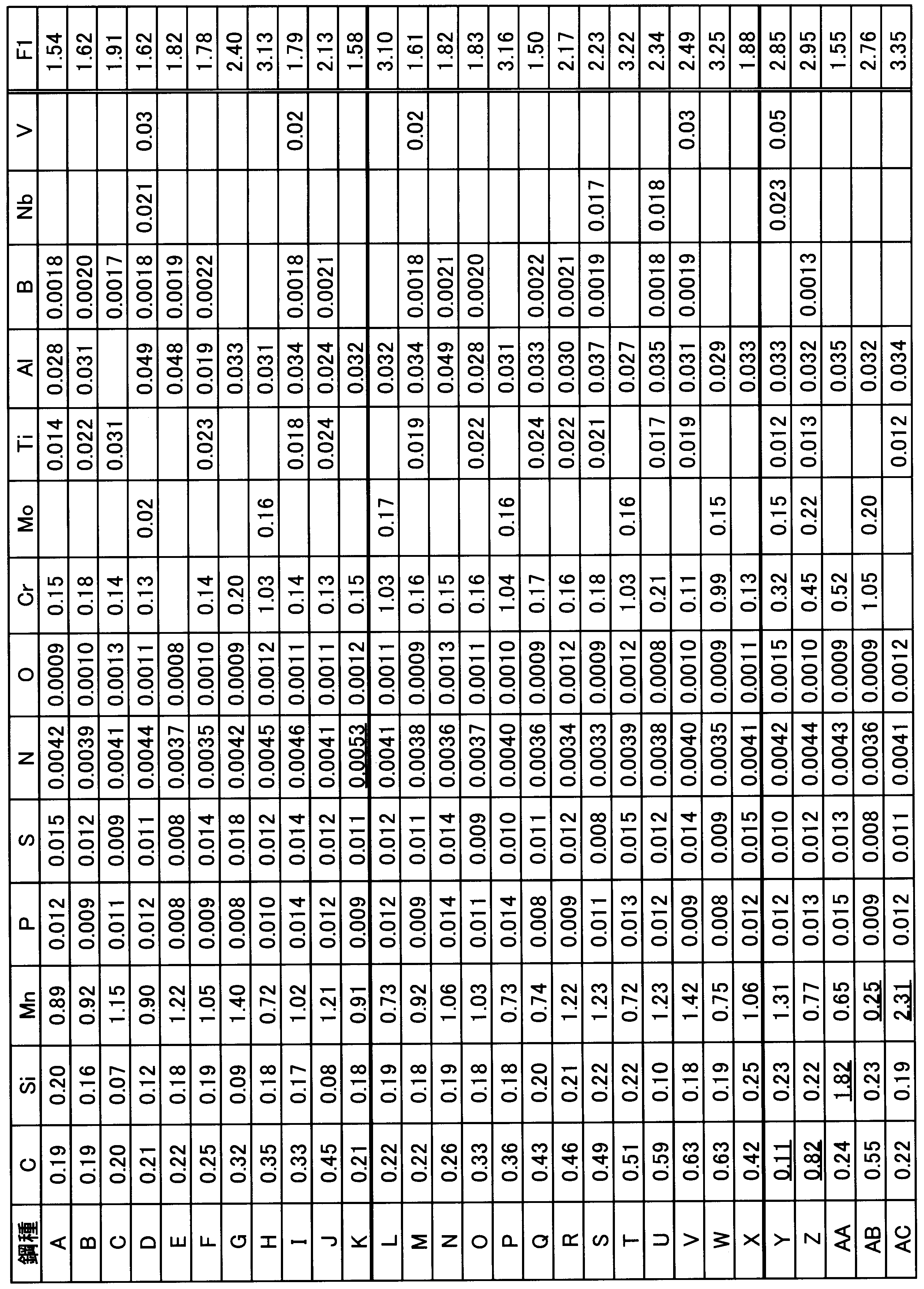

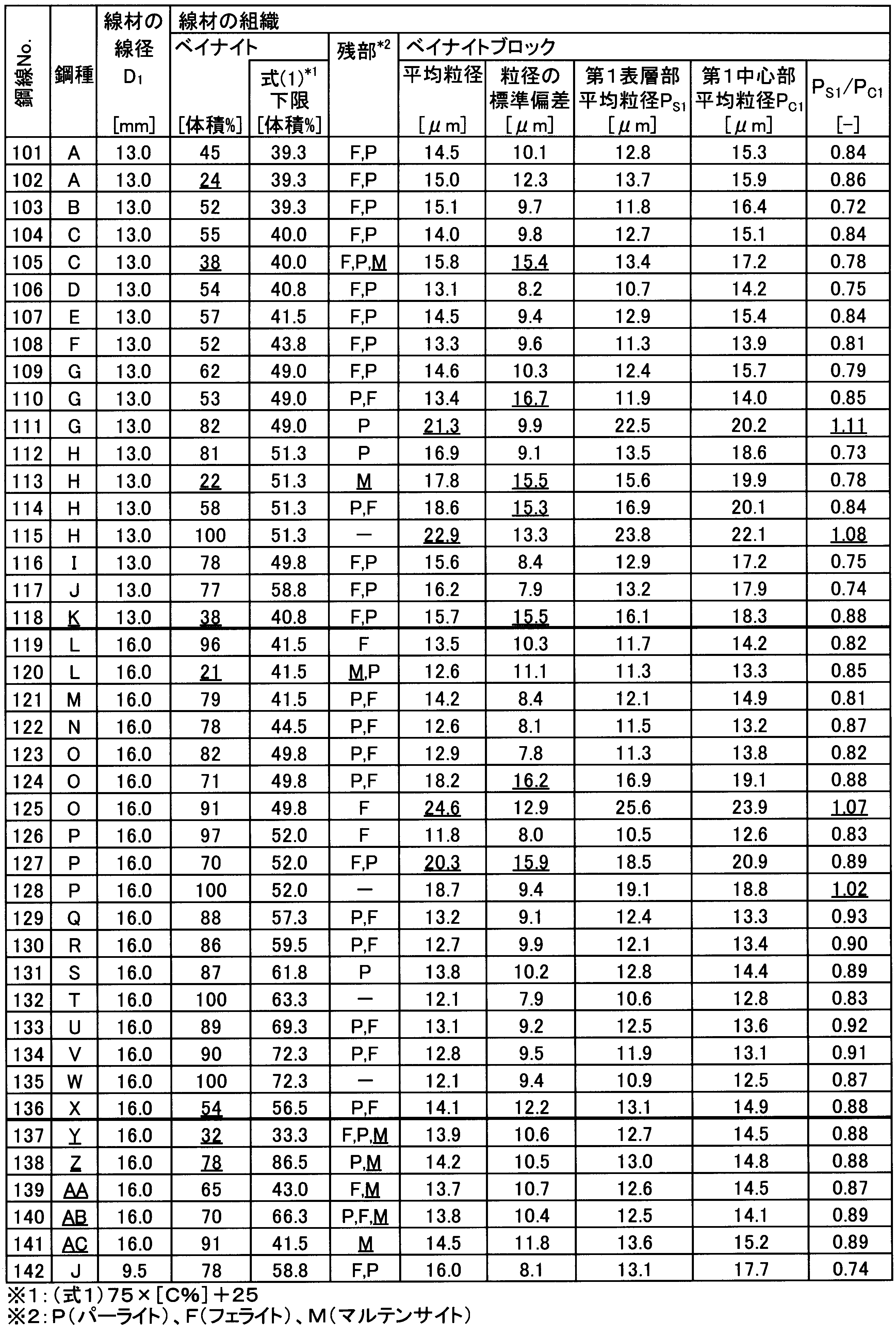
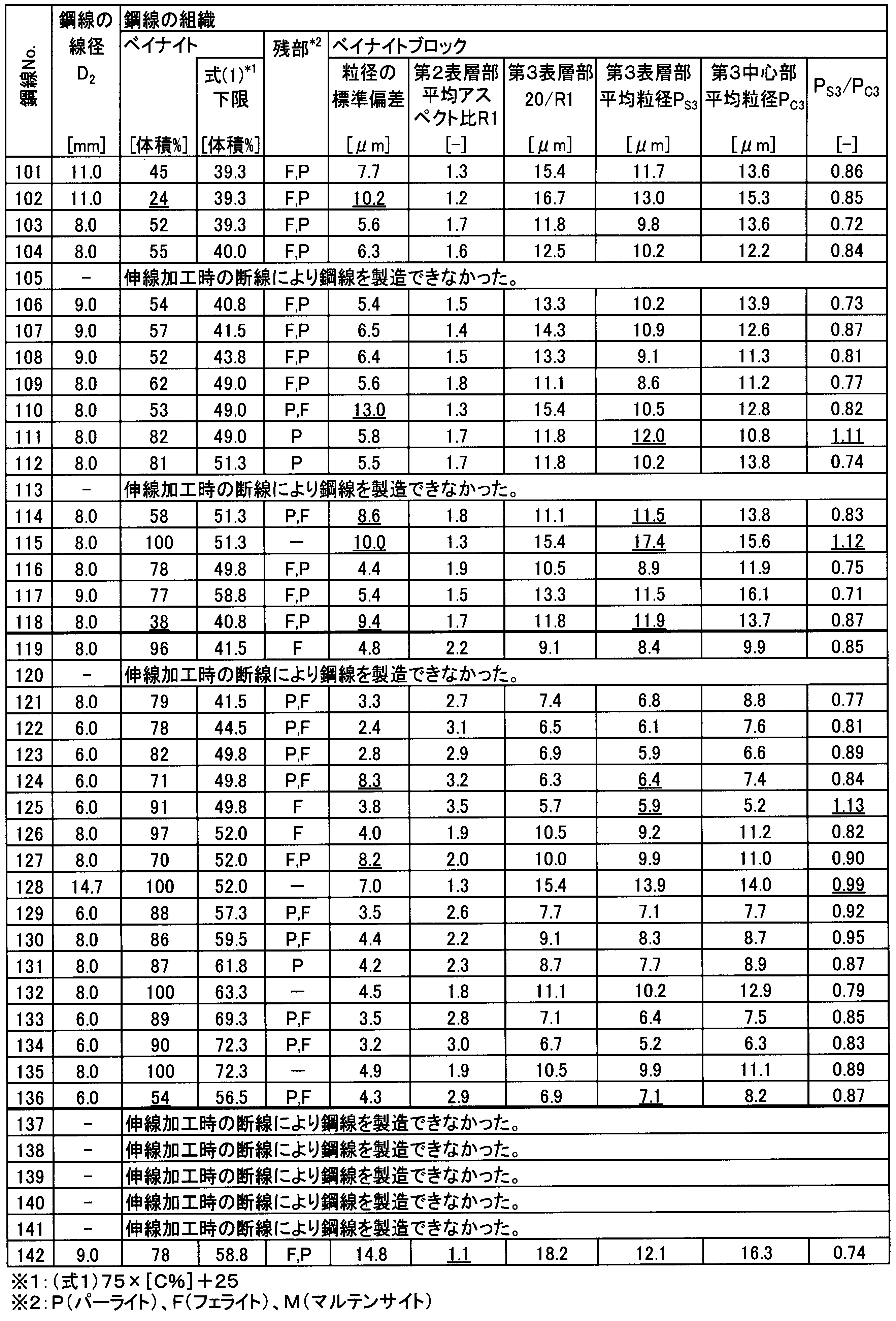
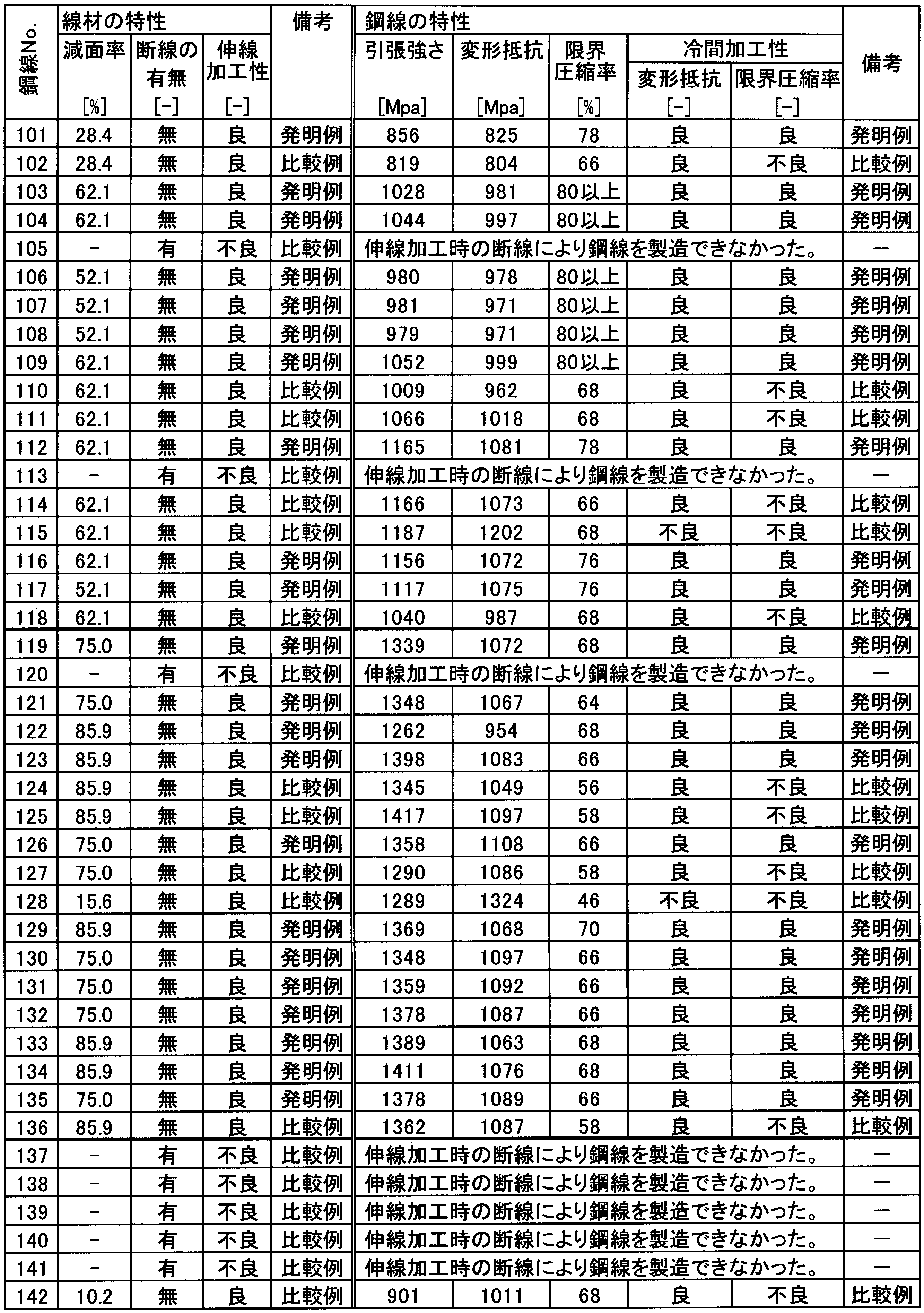
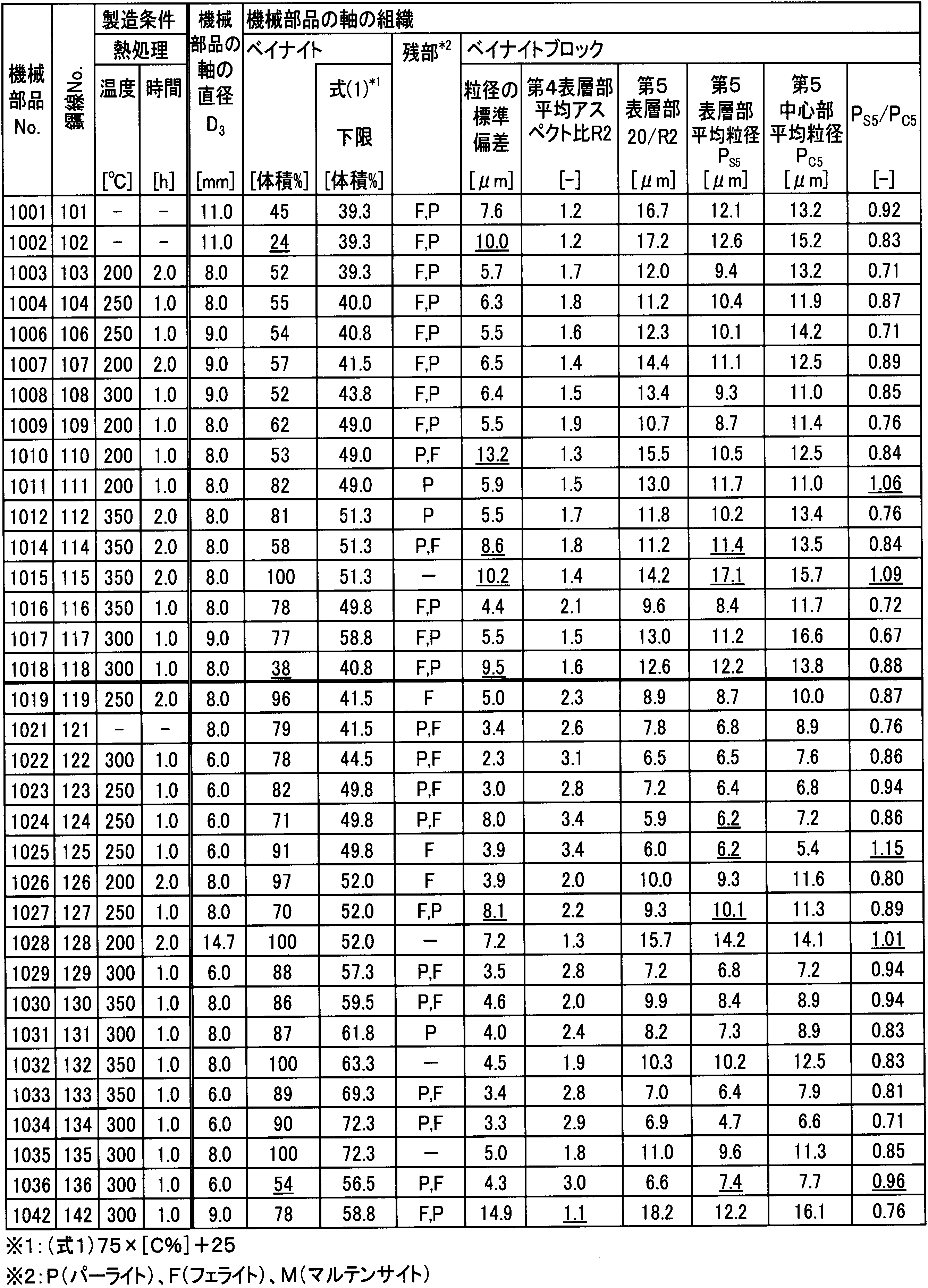
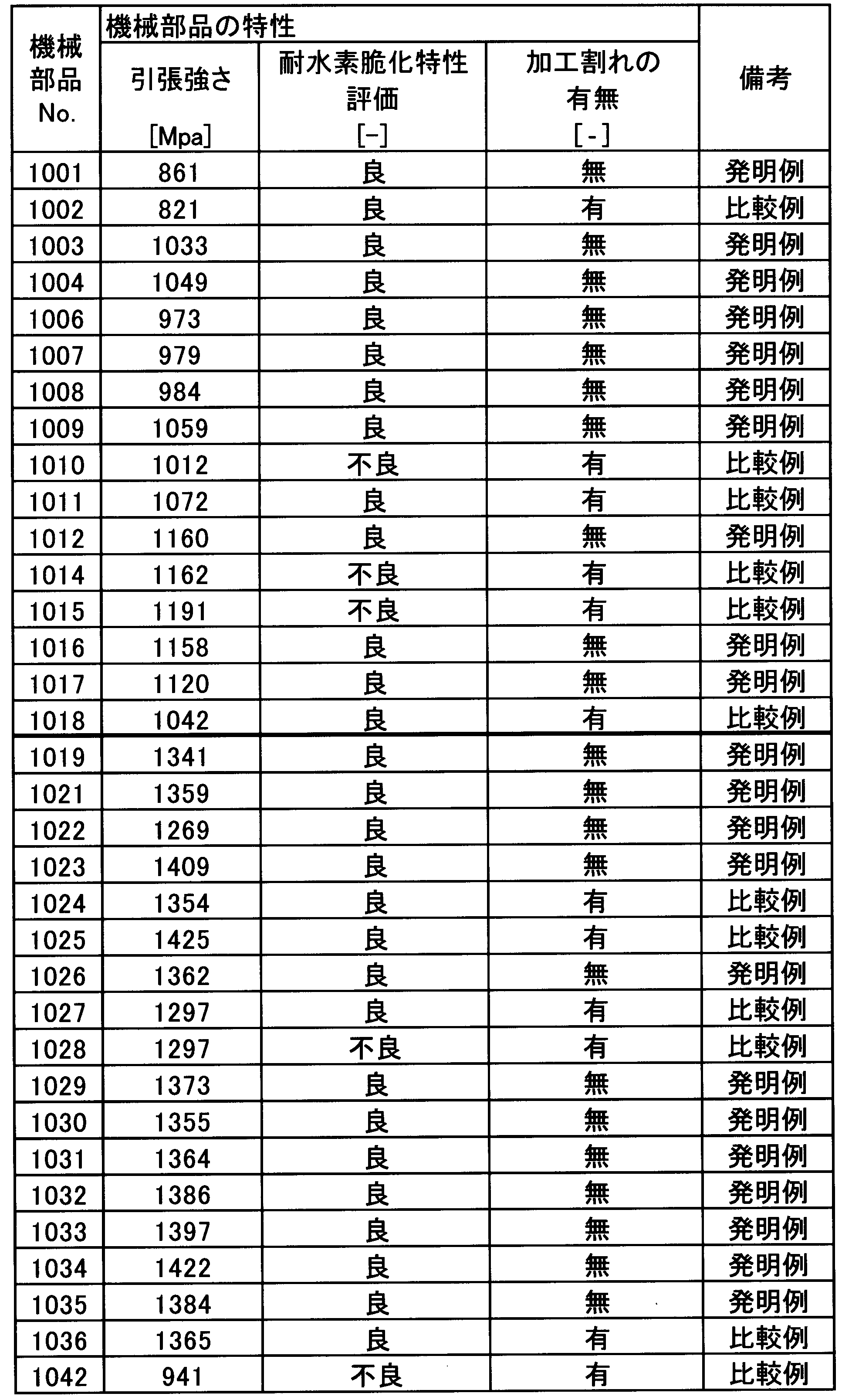
鋼線No.137は、C含有量が少ないため、マルテンサイトが生成して、伸線加工時の断線により鋼線を製造できなかった。
鋼線No.138は、C含有量が多いため、マルテンサイトが生成して、伸線加工時の断線により鋼線を製造できなかった。
鋼線No.139は、Si含有量が多いため、マルテンサイトが生成して、伸線加工時の断線により鋼線を製造できなかった。
鋼線No.140は、Mn含有量が少ないため、マルテンサイトが生成して、伸線加工時の断線により鋼線を製造できなかった。
鋼線No.141は、Mn含有量が多いため、マルテンサイトが生成して、伸線加工時の断線により鋼線を製造できなかった。
その結果、線材として良好な伸線加工性は得られたものの、鋼線として良好な冷間加工性を得ることは出来なかった。
また、鋼線No.102、110、111、114、115、118、124、125、127、128、136及び142を用いて冷間鍛造により製造した機械部品No.1002、1010、1011、1014、1015、1018、1024、1025、1027、1028、1036及び1042は、上記のいずれかの性質の1つ以上を満たすことができなかった。その結果、良好な耐水素脆化特性が得られないか、加工割れが起きていた。もしくは、その両方であった。
この高強度機械部品は、自動車、各種産業機械、及び、建設用部材の軽量化や小型化に寄与することが出来る。
よって、本発明は、自動車、各種産業機械及び建設産業において利用可能性が高く、産業上の貢献が、極めて顕著である。
2 線材の直径D1
3 断面の中心
4 第1表層部
5 第1中心部
11 鋼線の長手方向に平行な断面
12 鋼線の直径D2
13 断面の中心線
14 第2表層部
21 鋼線の長手方向に垂直な断面
23 断面の中心
24 第3表層部
25 第3中心部
31 機械部品の軸の長手方向に平行な断面
32 機械部品の軸の直径D3
33 断面の中心線
34 第4表層部
41 機械部品の軸の長手方向に垂直な断面
43 断面の中心
44 第5表層部
45 第5中心部
Claims (14)
- 鋼線であって、
化学成分として、質量%で、
C:0.18%~0.65%、
Si:0.05%~1.5%、
Mn:0.50%~2.0%、
Cr:0%~1.50%、
Mo:0%~0.50%、
Ti:0%~0.050%、
Al:0%~0.050%、
B:0%~0.0050%、
Nb:0%~0.050%、
V:0%~0.20%を含有し、
P:0.030%以下、
S:0.030%以下、
N:0.0050%以下、
O:0.01%以下に制限され、
残部がFe及び不純物であり;
質量%での前記Cの含有量を[C%]とするとき、組織が、体積%で75×[C%]+25以上のベイナイトを含み、残部が、フェライト及びパーライトの1つ以上であり;
前記鋼線の長手方向に平行な断面において、前記鋼線の直径をD2mmとし、前記鋼線の表面から前記断面の中心線に向かって深さ0.1×D2mmまでの領域を前記鋼線の第2表層部とし、前記鋼線の第2表層部におけるベイナイトブロックの平均アスペクト比をR1とするとき、
前記R1が1.2以上であり;
前記鋼線の長手方向に垂直な断面において、前記鋼線の直径をD2mmとし、前記鋼線の表面から前記断面の中心に向かって深さ0.1×D2mmまでの領域を前記鋼線の第3表層部、深さ0.25×D2mmから前記断面の中心までの領域を前記鋼線の第3中心部とし、前記鋼線の第3表層部における前記ベイナイトブロックの平均粒径をPS3μm、前記鋼線の第3中心部における前記ベイナイトブロックの平均粒径をPC3μmとするとき、
前記PS3が下記式(c)を満たしてかつ、
前記PS3と前記PC3とが下記式(d)を満たし;
前記組織における前記ベイナイトブロックの粒径の標準偏差が8.0μm以下であり;
引張強さが800MPa~1600MPaである
ことを特徴とする非調質機械部品用鋼線。
PS3≦20/R1・・・(c)
PS3/PC3≦0.95・・・(d) - 前記化学成分として、質量%で、C:0.18%~0.50%、Si:0.05%~0.50%を含有することを特徴とする請求項1に記載の非調質機械部品用鋼線。
- 前記化学成分として、質量%で、C:0.20%~0.65%を含有し、
質量%で前記Cの含有量を[C%]とするとき、前記組織が、体積%で45×[C%]+50以上の前記ベイナイトを含むことを特徴とする請求項1に記載の非調質機械部品用鋼線。 - 前記化学成分として、質量%で、B:0.0005%未満を含有し、
質量%で、前記Cの含有量を[C%]とし、前記Siの含有量を[Si%]とし、前記Mnの含有量を[Mn%]とし、前記Crの含有量を[Cr%]とし、前記Moの含有量を[Mo%]とするとき、下記式(b)で求められるF1が2.0以上であることを特徴とする請求項1から3のいずれか1項に記載の非調質機械部品用鋼線。
F1=0.6×[C%]-0.1×[Si%]+1.4×[Mn%]+1.3×[Cr%]+3.7×[Mo%]・・・(b) - 前記R1が2.0以下であることを特徴とする請求項1に記載の非調質機械部品用鋼線。
- 前記組織が、体積%で45×[C%]+50以上の前記ベイナイトを含むことを特徴とする請求項1に記載の非調質機械部品用鋼線。
- 請求項1~6いずれか1項に記載の非調質機械部品用鋼線を得るための線材であって、
化学成分として、質量%で、
C:0.18%~0.65%、
Si:0.05%~1.5%、
Mn:0.50%~2.0%、
Cr:0%~1.50%、
Mo:0%~0.50%、
Ti:0%~0.050%、
Al:0%~0.050%、
B:0%~0.0050%、
Nb:0%~0.050%、
V:0%~0.20%を含有し、
P:0.030%以下、
S:0.030%以下、
N:0.0050%以下、
O:0.01%以下に制限され、
残部がFe及び不純物であり;
質量%での前記Cの含有量を[C%]とするとき、組織が、体積%で75×[C%]+25以上のベイナイトを含み、残部が、マルテンサイトを含まないフェライト及びパーライトの1つ以上であり;
前記組織のベイナイトブロックの平均粒径が5.0μm~20.0μmであり、前記ベイナイトブロックの粒径の標準偏差が15.0μm以下であり;
前記線材の長手方向に垂直な断面において、前記線材の直径をD1mmとし、前記線材の表面から前記断面の中心に向かって深さ0.1×D1mmまでの領域を前記線材の第1表層部、深さ0.25×D1mmから前記断面の中心までの領域を前記線材の第1中心部としたとき、前記第1表層部での前記ベイナイトブロックの平均粒径をPS1μmと、前記第1中心部での前記ベイナイトブロックの平均粒径をPC1μmとが、下記式(a)を満たす
ことを特徴とする非調質機械部品用線材。
PS1/PC1≦0.95・・・(a) - 前記化学成分として、質量%で、C:0.18%~0.50%、Si:0.05%~0.50%を含有することを特徴とする請求項7に記載の非調質機械部品用線材。
- 前記化学成分として、質量%で、C:0.20%~0.65%を含有し、
質量%で前記Cの含有量を[C%]とするとき、前記組織が、体積%で45×[C%]+50以上の前記ベイナイトを含むことを特徴とする請求項7に記載の非調質機械部品用線材。 - 円柱の軸を有する機械部品であって、
化学成分として、質量%で、
C:0.18%~0.65%、
Si:0.05%~1.5%、
Mn:0.50%~2.0%、
Cr:0%~1.50%、
Mo:0%~0.50%、
Ti:0%~0.050%、
Al:0%~0.050%、
B:0%~0.0050%、
Nb:0%~0.050%、
V:0%~0.20%を含有し、
P:0.030%以下、
S:0.030%以下、
N:0.0050%以下、
O:0.01%以下に制限され、
残部がFe及び不純物であり;
質量%での前記Cの含有量を[C%]とするとき、組織が、体積%で75×[C%]+25%以上のベイナイトを含み、残部が、フェライト及びパーライトの1つ以上であり;
前記軸の長手方向に平行な断面において、前記軸の直径をD3mmとし、前記軸の表面から前記断面の中心線に向かって深さ0.1×D3mmまでの領域を前記機械部品の第4表層部とし、前記機械部品の第4表層部におけるベイナイトブロックの平均アスペクト比をR2とするとき、
前記R2が1.2以上であり;
前記軸の長手方向に垂直な断面において、前記軸の直径をD3mmとし、前記軸の表面から前記断面の中心に向かって深さ0.1×D3mmまでの領域を前記機械部品の第5表層部、深さ0.25×D3mmから前記断面の中心までの領域を前記機械部品の第5中心部とし、前記機械部品の第5表層部における前記ベイナイトブロックの平均粒径をPS5μm、前記機械部品の第5中心部における前記ベイナイトブロックの平均粒径をPC5μmとするとき、
前記PS5が下記式(e)を満たしてかつ、
前記PS5と前記PC5とが下記式(f)を満たし;
前記組織における前記ベイナイトブロックの粒径の標準偏差が8.0μm以下であり、
引張強さが800MPa~1600MPaである
ことを特徴とする非調質機械部品。
PS5≦20/R2・・・(e)
PS5/PC5≦0.95・・・(f) - 請求項1~6のいずれか1項に記載の鋼線を冷間加工して得られる非調質機械部品であることを特徴とする請求項10に記載の非調質機械部品。
- 前記R2が1.5以上であり、前記引張強さが1200MPa~1600MPaであることを特徴とする請求項10または11に記載の非調質機械部品。
- 前記D2と前記D3とが等しいことを特徴とする請求項10または11に記載の非調質機械部品。
- 前記非調質機械部品はボルトであることを特徴とする請求項10~13のいずれか1項に記載の非調質機械部品。
Priority Applications (7)
| Application Number | Priority Date | Filing Date | Title |
|---|---|---|---|
| US15/546,063 US10457998B2 (en) | 2015-01-27 | 2016-01-27 | Wire rod for non heat-treated mechanical part, steel wire for non heat-treated mechanical part, and non heat-treated mechanical part |
| KR1020177020700A KR101961579B1 (ko) | 2015-01-27 | 2016-01-27 | 비조질 기계 부품용 선재, 비조질 기계 부품용 강선 및 비조질 기계 부품 |
| MX2017009616A MX2017009616A (es) | 2015-01-27 | 2016-01-27 | Material de varilla para componentes de maquinas sin revenir, varillas de acero para componentes de maquinas sin revenir y componentes de maquinas sin revenir. |
| EP16743423.2A EP3252184A4 (en) | 2015-01-27 | 2016-01-27 | Rod material for non-tempered machine component, steel rod for non-tempered machine component, and non-tempered machine component |
| JP2016572105A JP6607199B2 (ja) | 2015-01-27 | 2016-01-27 | 非調質機械部品用線材、非調質機械部品用鋼線、及び、非調質機械部品 |
| MYPI2017702674A MY186409A (en) | 2015-01-27 | 2016-01-27 | Wire rod for non heat-treated mechanical part, steel wire for non heat-treated mechanical part, and non heat-treated mechanical part |
| CN201680007086.8A CN107208239B (zh) | 2015-01-27 | 2016-01-27 | 非调质机械部件用线材、非调质机械部件用钢线及非调质机械部件 |
Applications Claiming Priority (4)
| Application Number | Priority Date | Filing Date | Title |
|---|---|---|---|
| JP2015-013385 | 2015-01-27 | ||
| JP2015013385 | 2015-01-27 | ||
| JP2015030891 | 2015-02-19 | ||
| JP2015-030891 | 2015-02-19 |
Publications (1)
| Publication Number | Publication Date |
|---|---|
| WO2016121820A1 true WO2016121820A1 (ja) | 2016-08-04 |
Family
ID=56543430
Family Applications (1)
| Application Number | Title | Priority Date | Filing Date |
|---|---|---|---|
| PCT/JP2016/052351 Ceased WO2016121820A1 (ja) | 2015-01-27 | 2016-01-27 | 非調質機械部品用線材、非調質機械部品用鋼線、及び、非調質機械部品 |
Country Status (8)
| Country | Link |
|---|---|
| US (1) | US10457998B2 (ja) |
| EP (1) | EP3252184A4 (ja) |
| JP (1) | JP6607199B2 (ja) |
| KR (1) | KR101961579B1 (ja) |
| CN (1) | CN107208239B (ja) |
| MX (1) | MX2017009616A (ja) |
| TW (1) | TWI609975B (ja) |
| WO (1) | WO2016121820A1 (ja) |
Cited By (12)
| Publication number | Priority date | Publication date | Assignee | Title |
|---|---|---|---|---|
| JP2019094535A (ja) * | 2017-11-22 | 2019-06-20 | 日本製鉄株式会社 | 機械構造用鋼およびその切削方法 |
| JP6645638B1 (ja) * | 2018-10-30 | 2020-02-14 | Jfeスチール株式会社 | ボルト用鋼 |
| WO2020090149A1 (ja) * | 2018-10-30 | 2020-05-07 | Jfeスチール株式会社 | ボルト用鋼及びその製造方法 |
| CN114000048A (zh) * | 2021-09-29 | 2022-02-01 | 武钢集团昆明钢铁股份有限公司 | 一种公称直径12.5mm的预应力钢绞线用SWRH82B热轧盘条及其制备方法 |
| JP2022512514A (ja) * | 2018-12-18 | 2022-02-04 | ポスコ | 軟質化熱処理の省略が可能な線材及びその製造方法 |
| CN115464073A (zh) * | 2022-10-09 | 2022-12-13 | 泰安众科建材有限公司 | 用碳素弹簧钢丝和点焊技术制备高强度弹簧钢丝网 |
| JP2024031942A (ja) * | 2022-08-23 | 2024-03-07 | Jfeスチール株式会社 | 鋼部品およびその製造方法 |
| WO2024106398A1 (ja) * | 2022-11-18 | 2024-05-23 | Jfeスチール株式会社 | 熱間鍛造非調質鋼およびその製造方法 |
| WO2024204819A1 (ja) * | 2023-03-31 | 2024-10-03 | 日本製鉄株式会社 | 線材、鋼線、及び機械部品 |
| WO2024204820A1 (ja) * | 2023-03-31 | 2024-10-03 | 日本製鉄株式会社 | 鋼線及び機械部品 |
| JP2024543998A (ja) * | 2021-12-01 | 2024-11-26 | ポスコ カンパニー リミテッド | 耐遅れ破壊抵抗性が向上した冷間鍛造用線材、鋼部品及びその製造方法 |
| KR20250149785A (ko) | 2023-03-15 | 2025-10-16 | 닛폰세이테츠 가부시키가이샤 | 볼트 |
Families Citing this family (18)
| Publication number | Priority date | Publication date | Assignee | Title |
|---|---|---|---|---|
| KR102090227B1 (ko) * | 2017-12-20 | 2020-03-17 | 주식회사 포스코 | 고강도 선재 및 지연파괴 저항성이 우수한 고강도 강재와 그 제조방법 |
| KR102090226B1 (ko) * | 2017-12-20 | 2020-03-17 | 주식회사 포스코 | 고강도 선재 및 지연파괴 저항성이 우수한 고강도 강재와 그 제조방법 |
| CN108642375B (zh) * | 2018-04-23 | 2020-09-29 | 包头钢铁(集团)有限责任公司 | 非调质微合金钢管和非调质微合金钢管的制造方法 |
| CN110055450B (zh) * | 2019-04-18 | 2021-04-20 | 石钢京诚装备技术有限公司 | 一种非调质钢的冶炼方法 |
| KR102314433B1 (ko) * | 2019-12-17 | 2021-10-19 | 주식회사 포스코 | 우수한 수소취성 저항성을 가지는 고강도 냉간압조용 선재 및 그 제조방법 |
| CN111206191B (zh) * | 2020-03-06 | 2021-08-27 | 马鞍山钢铁股份有限公司 | 一种Ti-V复合微合金化超细贝氏体非调质钢及其控锻控冷工艺和生产工艺 |
| CN112410670B (zh) * | 2020-11-18 | 2022-02-01 | 北京交通大学 | 一种贝氏体/马氏体型非调质钢 |
| KR102448753B1 (ko) * | 2020-11-27 | 2022-09-30 | 주식회사 포스코 | 절삭성 및 충격인성이 향상된 중탄소 비조질 선재 및 그 제조방법 |
| KR102492644B1 (ko) * | 2020-12-18 | 2023-01-30 | 주식회사 포스코 | 지연파괴 저항성이 향상된 선재, 부품 및 그 제조방법 |
| KR102492631B1 (ko) * | 2020-12-18 | 2023-01-30 | 주식회사 포스코 | 지연파괴 저항성이 향상된 볼트용 선재, 부품 및 그 제조방법 |
| CN112899572A (zh) * | 2021-01-19 | 2021-06-04 | 青海西钢特殊钢科技开发有限公司 | 一种高性能的非调质塑机哥林柱用qglz-x钢及生产方法 |
| CN115386802B (zh) * | 2022-08-31 | 2023-07-25 | 马鞍山钢铁股份有限公司 | 一种10.9级大规格风电螺栓用非调质钢及其生产方法 |
| CN115572910B (zh) * | 2022-10-31 | 2023-06-27 | 西安建筑科技大学 | 一种高强度汽车曲轴用非调质钢及其制备方法 |
| CN116162853B (zh) * | 2023-02-17 | 2025-11-28 | 上海大学(浙江)高端装备基础件材料研究院 | 一种12.9级非调质长杆螺栓用钢及其制备方法 |
| CN120366554B (zh) * | 2025-06-27 | 2025-09-23 | 江苏永钢集团有限公司 | 一种1200MPa级高强度工具钢盘条及其制造方法 |
| CN120366556B (zh) * | 2025-06-27 | 2025-09-19 | 江苏永钢集团有限公司 | 一种1300MPa级高强度工具钢盘条及其制造方法 |
| CN120366553B (zh) * | 2025-06-27 | 2025-09-23 | 江苏永钢集团有限公司 | 一种1150MPa级高强度工具钢盘条及其制造方法 |
| CN120366555B (zh) * | 2025-06-27 | 2025-09-23 | 江苏永钢集团有限公司 | 一种1250MPa级高强度工具钢盘条及其制造方法 |
Citations (4)
| Publication number | Priority date | Publication date | Assignee | Title |
|---|---|---|---|---|
| JPH02166229A (ja) * | 1988-12-20 | 1990-06-26 | Toa Steel Co Ltd | 非調質ボルト用鋼線材の製造方法 |
| JPH0841537A (ja) * | 1994-07-29 | 1996-02-13 | Kobe Steel Ltd | 高強度高靭性ボルト用鋼材の製法 |
| JPH11315347A (ja) * | 1998-04-30 | 1999-11-16 | Kobe Steel Ltd | 耐遅れ破壊性に優れた高強度線材およびその製造方法並びに高強度ボルト |
| WO2013031640A1 (ja) * | 2011-08-26 | 2013-03-07 | 新日鐵住金株式会社 | 非調質機械部品用線材、非調質機械部品用鋼線、及び、非調質機械部品とそれらの製造方法 |
Family Cites Families (12)
| Publication number | Priority date | Publication date | Assignee | Title |
|---|---|---|---|---|
| JPH11315349A (ja) | 1998-04-30 | 1999-11-16 | Kobe Steel Ltd | 耐遅れ破壊性に優れた高強度線材およびその製造方法並びに高強度ボルト |
| JP3457192B2 (ja) | 1998-11-09 | 2003-10-14 | 株式会社神戸製鋼所 | 冷間鍛造性に優れた中高炭素鋼 |
| JP3940270B2 (ja) | 2000-04-07 | 2007-07-04 | 本田技研工業株式会社 | 耐遅れ破壊性および耐リラクセーション特性に優れた高強度ボルトの製造方法 |
| JP4477759B2 (ja) | 2000-09-06 | 2010-06-09 | 新日本製鐵株式会社 | 高強度圧延pc鋼棒およびその製造方法 |
| JP4009218B2 (ja) | 2003-04-07 | 2007-11-14 | 新日本製鐵株式会社 | 耐水素脆化特性に優れたボルトおよびその製造方法 |
| JP4423219B2 (ja) | 2004-03-02 | 2010-03-03 | 本田技研工業株式会社 | 耐遅れ破壊特性及び耐リラクセーション特性に優れた高強度ボルト |
| JP5000367B2 (ja) | 2007-04-13 | 2012-08-15 | 新日本製鐵株式会社 | 耐水素脆化特性に優れた高強度亜鉛めっきボルト |
| JP5195009B2 (ja) * | 2008-05-13 | 2013-05-08 | 新日鐵住金株式会社 | 焼鈍後の冷間鍛造性に優れた鋼線材及びその製造方法 |
| KR101382664B1 (ko) * | 2009-11-17 | 2014-04-07 | 신닛테츠스미킨 카부시키카이샤 | 저온 어닐링용 강선 및 그 제조 방법 |
| JP5521885B2 (ja) * | 2010-08-17 | 2014-06-18 | 新日鐵住金株式会社 | 高強度かつ耐水素脆化特性に優れた機械部品用鋼線、および機械部品とその製造方法 |
| EP2843074B1 (en) * | 2012-04-23 | 2018-03-21 | Nippon Steel & Sumitomo Metal Corporation | Rail |
| CN105308202B (zh) | 2013-06-13 | 2017-04-26 | 新日铁住金株式会社 | 抗拉强度为950~1600MPa 的珠光体组织螺栓用的钢丝的制造用的线材、抗拉强度为950~1600MPa 的珠光体组织螺栓用的钢丝、珠光体组织螺栓及它们的制造方法 |
-
2016
- 2016-01-27 WO PCT/JP2016/052351 patent/WO2016121820A1/ja not_active Ceased
- 2016-01-27 EP EP16743423.2A patent/EP3252184A4/en not_active Withdrawn
- 2016-01-27 MX MX2017009616A patent/MX2017009616A/es unknown
- 2016-01-27 US US15/546,063 patent/US10457998B2/en not_active Expired - Fee Related
- 2016-01-27 JP JP2016572105A patent/JP6607199B2/ja active Active
- 2016-01-27 KR KR1020177020700A patent/KR101961579B1/ko active Active
- 2016-01-27 TW TW105102524A patent/TWI609975B/zh not_active IP Right Cessation
- 2016-01-27 CN CN201680007086.8A patent/CN107208239B/zh active Active
Patent Citations (4)
| Publication number | Priority date | Publication date | Assignee | Title |
|---|---|---|---|---|
| JPH02166229A (ja) * | 1988-12-20 | 1990-06-26 | Toa Steel Co Ltd | 非調質ボルト用鋼線材の製造方法 |
| JPH0841537A (ja) * | 1994-07-29 | 1996-02-13 | Kobe Steel Ltd | 高強度高靭性ボルト用鋼材の製法 |
| JPH11315347A (ja) * | 1998-04-30 | 1999-11-16 | Kobe Steel Ltd | 耐遅れ破壊性に優れた高強度線材およびその製造方法並びに高強度ボルト |
| WO2013031640A1 (ja) * | 2011-08-26 | 2013-03-07 | 新日鐵住金株式会社 | 非調質機械部品用線材、非調質機械部品用鋼線、及び、非調質機械部品とそれらの製造方法 |
Non-Patent Citations (1)
| Title |
|---|
| See also references of EP3252184A4 * |
Cited By (25)
| Publication number | Priority date | Publication date | Assignee | Title |
|---|---|---|---|---|
| JP7175082B2 (ja) | 2017-11-22 | 2022-11-18 | 日本製鉄株式会社 | 機械構造用鋼およびその切削方法 |
| JP2019094535A (ja) * | 2017-11-22 | 2019-06-20 | 日本製鉄株式会社 | 機械構造用鋼およびその切削方法 |
| CN112969808B (zh) * | 2018-10-30 | 2022-09-13 | 杰富意钢铁株式会社 | 螺栓用钢及其制造方法 |
| CN112969808A (zh) * | 2018-10-30 | 2021-06-15 | 杰富意钢铁株式会社 | 螺栓用钢及其制造方法 |
| WO2020090149A1 (ja) * | 2018-10-30 | 2020-05-07 | Jfeスチール株式会社 | ボルト用鋼及びその製造方法 |
| JP6645638B1 (ja) * | 2018-10-30 | 2020-02-14 | Jfeスチール株式会社 | ボルト用鋼 |
| US12203149B2 (en) | 2018-10-30 | 2025-01-21 | Jfe Steel Corporation | Steel for bolts, and method of manufacturing same |
| JP2022512514A (ja) * | 2018-12-18 | 2022-02-04 | ポスコ | 軟質化熱処理の省略が可能な線材及びその製造方法 |
| US12281368B2 (en) | 2018-12-18 | 2025-04-22 | Posco Co., Ltd | Wire rod of which softening heat treatment can be omitted, and manufacturing method therefor |
| CN114000048A (zh) * | 2021-09-29 | 2022-02-01 | 武钢集团昆明钢铁股份有限公司 | 一种公称直径12.5mm的预应力钢绞线用SWRH82B热轧盘条及其制备方法 |
| JP2024543998A (ja) * | 2021-12-01 | 2024-11-26 | ポスコ カンパニー リミテッド | 耐遅れ破壊抵抗性が向上した冷間鍛造用線材、鋼部品及びその製造方法 |
| JP2024031942A (ja) * | 2022-08-23 | 2024-03-07 | Jfeスチール株式会社 | 鋼部品およびその製造方法 |
| JP7697499B2 (ja) | 2022-08-23 | 2025-06-24 | Jfeスチール株式会社 | 鋼部品およびその製造方法 |
| CN115464073A (zh) * | 2022-10-09 | 2022-12-13 | 泰安众科建材有限公司 | 用碳素弹簧钢丝和点焊技术制备高强度弹簧钢丝网 |
| CN115464073B (zh) * | 2022-10-09 | 2023-08-18 | 泰安众科建材有限公司 | 用碳素弹簧钢丝和点焊技术制备高强度弹簧钢丝网 |
| JPWO2024106398A1 (ja) * | 2022-11-18 | 2024-05-23 | ||
| JP7597271B2 (ja) | 2022-11-18 | 2024-12-10 | Jfeスチール株式会社 | 熱間鍛造非調質鋼およびその製造方法 |
| WO2024106398A1 (ja) * | 2022-11-18 | 2024-05-23 | Jfeスチール株式会社 | 熱間鍛造非調質鋼およびその製造方法 |
| KR20250149785A (ko) | 2023-03-15 | 2025-10-16 | 닛폰세이테츠 가부시키가이샤 | 볼트 |
| JP7610174B1 (ja) * | 2023-03-31 | 2025-01-08 | 日本製鉄株式会社 | 線材、鋼線、及び機械部品 |
| JP7610175B1 (ja) * | 2023-03-31 | 2025-01-08 | 日本製鉄株式会社 | 鋼線及び機械部品 |
| WO2024204820A1 (ja) * | 2023-03-31 | 2024-10-03 | 日本製鉄株式会社 | 鋼線及び機械部品 |
| WO2024204819A1 (ja) * | 2023-03-31 | 2024-10-03 | 日本製鉄株式会社 | 線材、鋼線、及び機械部品 |
| KR20250168532A (ko) | 2023-03-31 | 2025-12-02 | 닛폰세이테츠 가부시키가이샤 | 선재, 강선, 및 기계 부품 |
| KR20250168484A (ko) | 2023-03-31 | 2025-12-02 | 닛폰세이테츠 가부시키가이샤 | 강선 및 기계 부품 |
Also Published As
| Publication number | Publication date |
|---|---|
| JPWO2016121820A1 (ja) | 2017-11-30 |
| TWI609975B (zh) | 2018-01-01 |
| JP6607199B2 (ja) | 2019-11-20 |
| CN107208239B (zh) | 2018-11-09 |
| KR20170099997A (ko) | 2017-09-01 |
| KR101961579B1 (ko) | 2019-03-22 |
| MX2017009616A (es) | 2017-10-18 |
| EP3252184A1 (en) | 2017-12-06 |
| US20180016658A1 (en) | 2018-01-18 |
| TW201636440A (zh) | 2016-10-16 |
| EP3252184A4 (en) | 2018-09-12 |
| US10457998B2 (en) | 2019-10-29 |
| CN107208239A (zh) | 2017-09-26 |
Similar Documents
| Publication | Publication Date | Title |
|---|---|---|
| JP6607199B2 (ja) | 非調質機械部品用線材、非調質機械部品用鋼線、及び、非調質機械部品 | |
| KR101599163B1 (ko) | 비조질 기계 부품용 선재, 비조질 기계 부품용 강선 및 비조질 기계 부품과 그들의 제조 방법 | |
| US11203797B2 (en) | Steel wire and wire rod | |
| JP6180351B2 (ja) | 生引き性に優れた高強度鋼線用線材および高強度鋼線 | |
| WO2011062012A1 (ja) | 低温焼鈍用鋼線及びその製造方法 | |
| JP5913214B2 (ja) | ボルト用鋼およびボルト、並びにそれらの製造方法 | |
| JP7469643B2 (ja) | 鋼線、非調質機械部品用線材、及び非調質機械部品 | |
| WO2018008698A1 (ja) | 線材、鋼線及び部品 | |
| JP6614349B2 (ja) | 圧延線材 | |
| KR102042062B1 (ko) | 냉간압조용 선재 및 이의 제조방법 | |
| WO2018061101A1 (ja) | 鋼 | |
| CN108368583B (zh) | 非调质机械部件用钢丝及非调质机械部件 | |
| JPWO2014199919A1 (ja) | 引張強さが950〜1600MPaであるパーライト組織ボルト用の鋼線の製造用の線材、引張強さが950〜1600MPaであるパーライト組織ボルト用の鋼線、パーライト組織ボルト、及び、それらの製造方法 |
Legal Events
| Date | Code | Title | Description |
|---|---|---|---|
| 121 | Ep: the epo has been informed by wipo that ep was designated in this application |
Ref document number: 16743423 Country of ref document: EP Kind code of ref document: A1 |
|
| ENP | Entry into the national phase |
Ref document number: 20177020700 Country of ref document: KR Kind code of ref document: A |
|
| WWE | Wipo information: entry into national phase |
Ref document number: 15546063 Country of ref document: US Ref document number: MX/A/2017/009616 Country of ref document: MX |
|
| ENP | Entry into the national phase |
Ref document number: 2016572105 Country of ref document: JP Kind code of ref document: A |
|
| NENP | Non-entry into the national phase |
Ref country code: DE |
|
| REEP | Request for entry into the european phase |
Ref document number: 2016743423 Country of ref document: EP |