WO2016121931A1 - 装飾体の製造方法及び装飾体及びスティック玩具 - Google Patents
装飾体の製造方法及び装飾体及びスティック玩具 Download PDFInfo
- Publication number
- WO2016121931A1 WO2016121931A1 PCT/JP2016/052668 JP2016052668W WO2016121931A1 WO 2016121931 A1 WO2016121931 A1 WO 2016121931A1 JP 2016052668 W JP2016052668 W JP 2016052668W WO 2016121931 A1 WO2016121931 A1 WO 2016121931A1
- Authority
- WO
- WIPO (PCT)
- Prior art keywords
- pair
- coupling
- decorative
- connection
- stick
- Prior art date
- Legal status (The legal status is an assumption and is not a legal conclusion. Google has not performed a legal analysis and makes no representation as to the accuracy of the status listed.)
- Ceased
Links
Images



Classifications
-
- A—HUMAN NECESSITIES
- A63—SPORTS; GAMES; AMUSEMENTS
- A63H—TOYS, e.g. TOPS, DOLLS, HOOPS OR BUILDING BLOCKS
- A63H33/00—Other toys
- A63H33/22—Optical, colour, or shadow toys
-
- A—HUMAN NECESSITIES
- A63—SPORTS; GAMES; AMUSEMENTS
- A63H—TOYS, e.g. TOPS, DOLLS, HOOPS OR BUILDING BLOCKS
- A63H33/00—Other toys
-
- B—PERFORMING OPERATIONS; TRANSPORTING
- B44—DECORATIVE ARTS
- B44C—PRODUCING DECORATIVE EFFECTS; MOSAICS; TARSIA WORK; PAPERHANGING
- B44C3/00—Processes, not specifically provided for elsewhere, for producing ornamental structures
- B44C3/12—Uniting ornamental elements to structures, e.g. mosaic plates
-
- B—PERFORMING OPERATIONS; TRANSPORTING
- B44—DECORATIVE ARTS
- B44C—PRODUCING DECORATIVE EFFECTS; MOSAICS; TARSIA WORK; PAPERHANGING
- B44C5/00—Processes for producing special ornamental bodies
- B44C5/04—Ornamental plaques, e.g. decorative panels, decorative veneers
-
- G—PHYSICS
- G09—EDUCATION; CRYPTOGRAPHY; DISPLAY; ADVERTISING; SEALS
- G09F—DISPLAYING; ADVERTISING; SIGNS; LABELS OR NAME-PLATES; SEALS
- G09F19/00—Advertising or display means not otherwise provided for
- G09F19/12—Advertising or display means not otherwise provided for using special optical effects
- G09F19/125—Stereoscopic displays; 3D displays
Definitions
- the present invention relates to a stick toy called a rainbow stick, a decoration used therefor, and a method of manufacturing the decoration.
- the rainbow stick is disposed between a first binding member fixed to the stick shaft, a second binding member moveably attached to the stick shaft, and the first binding member and the second binding member. It is a toy which consists of a plurality of bendable beltlike members, and the both ends of a beltlike member are attached to the 1st binding member and the 2nd binding member, respectively. This toy is to enjoy making various shapes such as a soap bubble, a jellyfish, and a sphere by changing the color appearing by rotating the stick shaft and deforming the strip-shaped member (Patent Document 1). The inventor, as vice chairman of the World Rainbow Stick Association, has made improvements on its production and sales.
- the manufacturing method of the conventional stick toy is demonstrated. First, a tape material or a sheet material is cut to a fixed length to prepare a strip-shaped member, and the end portions of each strip-shaped member are radially bonded to the first binding member made of disc pieces with their surface directions aligned. Thereafter, the other end of each strip-shaped member is attached to the second binding member in the same radial direction, with the same surface direction. Thereby, the tape spherical body which the both ends of the strip
- the stick shaft is inserted so as to pass through the centers of the first binding member and the second binding member, and the first binding member is fixed to the stick shaft and the second binding member is movably attached to the stick shaft .
- the second binding member is rotated relative to the first binding member fixed to the stick shaft, and the shape of the strip-shaped member is changed accordingly. In this way, it is possible to produce a stick toy that enjoys the change in the shape of the strip.
- the present invention proposes a decorative body used for a stick toy, a cover, a mobile, a lamp shade and the like with improved productivity and quality, and a method of manufacturing the decorative body.
- the present invention solves the problems by the following in order to achieve the above object.
- the method for producing a decorative body according to (1) characterized in that the pair of connection regions are joined in a ring shape.
- connection areas set in a flexible sheet, Forming a plurality of slits in the sheet between the pair of connection areas, and having a plurality of decorative bands separated at both ends while being connected to the pair of connection areas;
- the plurality of decorative bands are inverted with respect to the pair of connection areas such that the plurality of decorative bands draw an arc radially between the pair of connection areas, and the pair of connection areas are respectively coupled in a ring shape
- the pair of coupling members has a pair of approximately disc-like coupling members for coupling the pair of coupling regions in a ring shape
- the pair of coupling members includes a plurality of coupling projections protruding from the peripheral edge
- the pair of connection regions may include a plurality of connection slits into which the plurality of connection protrusions are inserted
- the decorative body according to (3) is provided, wherein the pair of connection areas are connected in a ring shape by inserting the plurality of connection protrusions into the plurality of connection slits.
- the decorative body according to any one of (3) to (5), A pair of holding plates which are installed to sandwich the pair of coupling members from the outside with a predetermined distance from the pair of coupling members, and having a diameter larger than that of the pair of coupling members, A through hole formed substantially at the center of the pair of coupling members and the pair of pressure plates; A stick inserted into the through hole and fixing one coupling member on the tip end side and holding the other coupling member in a movable state;
- the stick toy is characterized in that the pair of restraining plates are located outside the plurality of inverted decorative bands to restrict the plurality of decorative bands to spread.
- the stick toy according to (7) further comprising: an anti-entanglement plate disposed closer to the tip end of the stick than the one coupling member and preventing the plurality of decorative bands from being entangled. .
- a pair of connecting regions facing each other is set in a flexible sheet, and a plurality of decorative bands are formed between the pair of connecting regions, Since the plurality of decorative bands are inverted with respect to the connection area and the pair of connection areas are respectively connected in a ring shape, it can be manufactured easily and with high productivity.
- the stick toy according to the present invention can improve productivity and reduce costs by the characteristic joining member.
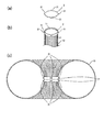
- FIG. It is an exploded view of the (a) sheet and the (b) joint member which are used for the decoration concerning the present invention.
- (A) shows a connecting member
- (b) shows a connecting region connected in a ring by the connecting member
- (c) shows a schematic diagram in which a pair of connecting members are connected in a ring.
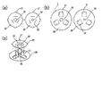
- FIG. It is a figure which shows the (a) coupling member used for a stick toy, (b) restraining member, and the coupling member and restraining member mutually connected with (c).
- (A) is the figure which combined the connection member and the pressing member
- (b) is a schematic cross section of a stick toy.
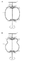
- (A) is a figure which shows an example of the shape which appears when rotating a stick toy
- (b) is a figure which shows an example of the shape which appears when rotating a stick toy. It is a figure which shows the sheet
- FIG. 1 is a figure which shows the sheet
- the sheet 1 is made of a flexible sheet material, and a synthetic resin film is preferably used.
- the sheet 1 is not limited in material as long as the decorative band described later has a degree of flexibility such that it can be inverted, and sheet materials derived from natural materials such as paper and wooden sheets, metals such as aluminum vapor deposition film It is also possible to use vapor deposited sheet materials and thin sheet materials of metals such as stainless steel.
- the sheet 1 may be a composite sheet material obtained by bonding a plurality of materials with an adhesive sheet, or a sheet material obtained by laminating a laminate sheet.
- the sheet 1 may be plain, but as shown in FIG. 6, printing, coloring and hologram processing of a design, an illustration and the like on the surface of the sheet 1 is particularly preferable because the decorative effect can be further enhanced.
- the thickness of the sheet 1 is preferably 10 ⁇ m to 100 ⁇ m in the case of using an aluminum deposited film, but this thickness is appropriately selected according to the flexibility of the sheet 1 and the use of the decorative body.
- the sheet material is cut into a size according to the purpose of the decorative body to produce a long sheet 1.
- a plurality of parallel slits 10 extending in the longitudinal direction are formed in the sheet 1.
- a pair of connecting areas 11 extending opposite to each other along the both ends of the sheet 1 is set without cutting all the sheets 1 from one end to the other end, and slits are made to connect between the connecting areas 11 Form 10
- one sheet 1 having a plurality of decorative bands 13 separated from each other while being connected at both ends in the pair of connection areas 11 is formed.
- the above corresponds to the decorative band forming step.
- the slit 10 is preferably formed in a linear shape, but may be formed in a curved shape. In addition, it is desirable that the slits 10 be formed at equal intervals, and that all the decorative bands 13 have the same width and the same shape. Note that adjacent decorative bands 13 may be cut out and thinned as necessary.
- the slit 10 can be formed in the sheet 1 using a known slit processing method.
- the slit 10 can be formed by a punching method using a cutter such as a Thomson blade, a laser cutting method, and a method using a cutting plotter.
- a cutter such as a Thomson blade
- a laser cutting method When the laser cutting method is used, gas may be generated in the portion where the slit 10 is formed during operation of the machine, and the gas may adhere to the transparent film as dirt. For this reason, it is preferable to perform laser cutting after laminating a protective sheet on the sheet 1 and then peel and remove the protective sheet.
- the sheet 1 may be excessively melted by the heat of the laser, so it is preferable to form the slit 10 by a cutting plotter or the like.
- the method using a cutting plotter is not suitable for cutting a thick sheet 1. Therefore, it is preferable to appropriately select the method of forming the slits 10 in accordance with the sheet 1.
- the formation of the decorative band 13 on the sheet 1 is automated, thereby achieving high productivity as compared with the belt-like member produced one by one by the conventional manual work. Can be efficiently produced with high precision.
- connection area 11 set along the short side of the sheet 1 a plurality of incisions to be the coupling slit 12 are arranged in the short direction of the sheet 1.
- the coupling slit 12 can be provided in the same manner as the slit 10.
- the coupling slits 12 are provided one more than the number of coupling projections 21 described later.
- the coupling protrusion 21 is provided on the periphery of the disk-shaped coupling member 2, and the coupling region 21 is deformed into a ring along the periphery of the coupling member 2, and the coupling projection 21 is inserted into the coupling slit 12.
- the decorative band 13 can be disposed in a cylindrical shape without breaks along the periphery of the coupling member 2. it can. Further, the length of the connection area 11 is formed longer than the entire width of the decorative band 13, that is, both ends of the connection area 11 project in the short direction with respect to the decorative band 13 arranged in the short direction of the sheet 1. By forming, when the connection area
- the coupling slits 12 positioned at both ends in the short side direction of the sheet 1 are provided with rings 1 by providing the sheet 1 in the vicinity of the decorative bands 13 positioned at both ends in the short side direction of the sheet 1.
- the decoration band 13 can form the continuous beautiful shape as a whole, without overlapping.
- FIG. 2 is a view showing a method of connecting the connecting area 11 in a ring shape by the connecting member 2.
- the coupling member 2 has a disk shape, and a plurality of coupling projections 21 that project corresponding to the coupling slit 12 are arranged at the periphery thereof.
- the number of the coupling protrusions 21 is appropriately determined so that the sheet 1 can be stably coupled according to the length of the coupling region 11 (short side of the sheet 1).
- the connection region 11 is fixed along the periphery of the connection member 2 by inserting the connection protrusion 21 into the connection slit 12.
- the coupling projections 21 are preferably formed to have a size capable of maintaining a sufficient holding force even after being inserted into the coupling slits 12. Further, depending on the material of the sheet 1 or the connecting member 2, the connecting protrusion 21 may fall off from the connecting slit 12. Therefore, the connecting protrusion 21 may be bent to prevent the falling off. Further, in the case where a material that is difficult to bend is used as the coupling member 2 or the like, the coupling projection 21 may be shaped like a key to prevent it from falling off. Furthermore, the coupling slit 12 and the coupling projection 21 may be fixed by an adhesive, or the end of the coupling region 11 may be adhered and fixed.
- the connecting member 2 since the connecting member 2 is used for the pair of connecting regions 11 of the sheet 1, two connecting members 2 are required for one decorative body.
- the decoration body is partially omitted and described.
- the bonding member 2 is preferably formed of a synthetic resin such as plastic, but cardboard, wood or the like may be used, or metal may be used.
- the connecting member 2 is preferably lightweight, and it is preferable to select and use an appropriate one according to the sheet 1 .
- the weight of the coupling member 2 does not have to be particularly limited if a support such as a spacer for holding the space between the pair of coupling members 2 is provided.
- one sheet 1 having a plurality of decorative bands 13 separated from each other with both ends connected to the connection area 11 was obtained.
- the decorative band 13 is inverted with respect to the connection area 11 so that the plurality of decorative bands 13 draw an arc radially between the pair of connection areas 11.
- the ring-like pair of connection areas 11 After being moved to the inside of the band 13, the pair of connecting areas 11 is moved to the outside of the plurality of decorative bands 13 from the same slit 10 while the upper and lower positions of the pair of connecting areas 11 are reversed. That is, the pair of connection areas 11 is moved such that the back surface of the coupling member 2 facing the inside of the plurality of decoration bands 13 is exposed to the outside of the plurality of decoration bands 13.
- the edges corresponding to the short sides of the sheet 1 face each other, and the connection parts with the decorative band 13 are directed in the opposite directions.
- the plurality of decorative bands 13 are inverted so as to surround the pair of connection areas 11 from the outside. That is, the decorative band 13 is inverted such that one side of the decorative band 13 exposed to the outside before the inversion is opposed to each other on one side of the pair of connection areas 11 and the inner side of the decorative band 13.
- the decorative band 13 is inverted so as to extend outward and curve from the connection portion with the pair of connection regions 11 without twisting and bending occurring in the connection portion with the pair of connection regions 11.
- a plurality of decoration belts 13 can be arranged so as to draw an arc radially between the pair of connection areas 11.
- the above corresponds to the reverse coupling step.
- the coupling region 11 is wound around the periphery of the coupling member 2 and coupled in a ring shape, and a plurality of decorative bands 13 draw an arc radially outward between the pair of coupling regions 11. It can be manufactured.
- the decorative body assembled by the above method can be used for indoor and outdoor decoration as art.
- the binding member 2 is suspended by a thread or the like to be used as a mobile
- by forming the decorative band 13 with the flexible sheet 1 it is possible to enjoy a unique shape change and obtain a healing effect. be able to.
- a luminaire such as an LED lamp between the pair of coupling members 2, it can be used as a cover or a lamp shade of the luminaire.
- the decorative body is preferably configured such that the decorative band 13 maintains a certain shape, for example, a spherical shape.
- the decorative band 13 can be configured to maintain a certain shape. Moreover, the decorative band 13 can also be firmly maintained by a fixed shape by comprising the sheet
- the sheet 1 is as described above, and for example, an aluminum vapor-deposited sheet can be used.
- a plurality of tapes are cut into short pieces of a predetermined length to prepare strip members, which are attached one by one. Therefore, in order to obtain colorful stick toys, it was necessary to align tapes of various colors.
- the stick toy according to the present invention by using a single sheet 1 in which the decorative band 13 is integrally connected to the connection area 11, the coloration of the predetermined pattern, the pattern at the targeted position of the sheet 1, And illustrations etc. can be printed. For this reason, it becomes possible to form beautiful patterns, colors and designs more easily than the conventional methods.
- the thickness of the sheet 1 of the stick toy is preferably 10 ⁇ m to 100 ⁇ m, and is preferably one having a high decorative effect such as coloring or hologram processing.
- the stick toy according to the present invention when the stick toy is rotated by using the sheet 1 having flexibility, the printing or the hologram processing such as the above-mentioned pattern etc. is combined, and the beauty appearance is more colorful than before.
- Can be The decorative band forming step is the same as described above.
- FIG. 3 is an exploded view of the connecting members 2A and 2B and the pressing plates 3A and 3B used in the stick toy of the present invention.
- the coupling members 2A and 2B of the stick toy according to the present invention have through holes 24 and 25 in the center so that the stick 4 having a long shape can be inserted as shown in FIG. 3 (a).
- the coupling members 2A and 2B are provided with coupling slits 23 for coupling with the pressure plates 3A and 3B, and the coupling projections 31 of the pressure plates 3A and 3B are fitted into the coupling slits 23.
- the material of the connecting members 2A and 2B is the same as that described above, but when the stick 4 is rotated, the stick toy is damaged by the weight of the connecting member 2B on the movable side in particular, and a beautiful shape change is obtained. It may not be possible to enjoy it. For this reason, it is preferable that the coupling members 2A and 2B be made of a lightweight material.
- the pressing plates 3A and 3B are fixed in a state of being separated from the coupling members 2A and 2B by a fixed interval by the fitting of the coupling projections 31. Further, the pressing plates 3A, 3B have a disk shape having a diameter larger than that of the coupling members 2A, 2B.
- the holding plates 3A and 3B are made of the same material as the coupling members 2A and 2B and are preferably made of a synthetic resin such as plastic, but cardboard and wood may be used, or metal may be used. good.
- the stick toy when the stick 4 is rotated, the stick toy may be damaged particularly by the weight of the movable pressing plate 3B, and it may not be possible to enjoy a beautiful change in shape. For this reason, it is preferable that the holding plates 3A and 3B be made of a lightweight material.
- the restraining plates 3A and 3B are arranged so as to sandwich the coupling members 2A and 2B from the outside (both end sides of the stick 4) together with the inverted decorative band 13 (sheet 1). Ru.
- the holding plates 3A, 3B can suppress the spread of the decorative band 13 in the radial direction of the plates 3A, 3B (in the direction orthogonal to the stick 4) because the base portion of the inverted decorative band 13 is suppressed.
- through holes 34, 35 for inserting the stick 4 are provided at the centers of the pressure plates 3A, 3B.
- coupling projections 31 for coupling with the coupling members 2A, 2B are provided in the plane of the holding plates 3A, 3B.
- the coupling projection 31 is formed by punching or the like in the plane of the pressure plates 3A, 3B, and as shown in FIG. 3C, when coupled with the coupling members 2A, 2B, substantially from the surface of the pressure plates 3A, 3B. It is launched vertically.
- a recess 32 is provided in the coupling projection 31, and the coupling projection 31 is fitted into the coupling slit 23, and the recess 32 is fitted and locked in the coupling slit 23.
- FIG. 3 (c) and FIG. 4 (a) the distance between the coupling members 2A and 2B and the pressing plates 3A and 3B. Can be kept constant.
- 3C shows the movable side coupling member 2B and the pressure plate 3B, which are disposed on the proximal end side of the stick 4.
- FIG. 4A shows the fixed side connecting member 2A and the pressing plate 3A, which are disposed on the tip end side of the stick 4.
- the fixture 5 is preferably formed of a cylindrical member or the like having a through hole of substantially the same diameter as the outer periphery of the stick 4.
- the through holes 24 of the coupling member 2A and the through holes 34 of the pressure plate 3A are preferably formed to have substantially the same diameter as the outer periphery of the stick 4.
- the through holes 25 of the coupling member 2B provided on the base end side of the stick 4 and the through holes 35 of the pressing plate 3B have a diameter larger than the outer periphery of the stick 4 and are installed movable with respect to the stick 4.
- the connecting projections 31 are inserted into the connecting slits 23 to suppress the connecting members 2A and 2B.
- the plates 3A, 3B are joined to produce the members of FIGS. 3 (c) and 4 (a).
- the reverse coupling step of attaching the coupling projections 21 of the coupling members 2A and 2B to the coupling slit 12 while inverting the decorative band 13 of the sheet 1 the pressing plates 3A and 3B suppress the root of the decorative band 13 as shown in FIG.
- the decorative band 13 forms a tape sphere that radially arcs outward.
- the decorative band 13 is partially omitted.
- the holding plates 3A and 3B regulate the spreading direction of the decorative band 13 so that the decorative band 13 is greatly protruded and curved in the radial direction of the holding plates 3A and 3B, and the outer shape of the stick toy is substantially elliptical Or perform the function of preparing almost a sphere.
- the stick toy according to the present invention may be provided with the anti-tangle plate 6 near the tip of the stick 4.
- FIG. 5 (a) and (b) the decorative band 13 is partially omitted and described. According to this configuration, it is possible to prevent the decorative band 13 from jumping over the tip of the stick 4 and being entangled when the stick toy rotates.
- the material of the anti-tangle plate 6 is preferably made of a synthetic resin such as plastic, but cardboard, wood or the like may be used, or metal may be used.
- you may print the image, illustration, character, etc. which have an advertising effect on the anti-tangle board 6.
- the anti-tangle plate 6 may be fixed to the stick 4 by a support or the like, but the anti-tangle plate 6 is installed in a movable state with respect to the stick 4 and the anti-tangle plate 6 is provided with a blade to rotate the stick toy At the same time, it may rotate like a propeller. According to this configuration, in addition to the deformation of the main body of the stick toy, it is also possible to enjoy the rotation of the anti-tangle plate 6 and the change of the design.
- the second embodiment according to the present invention can be applied to the above-described embodiment, that is, to the decorative body and the stick toy, and is for further enhancing their decorativeness.
- a sheet in which the position of the joint slit 12 is shifted is superimposed on the sheet 1 described above, and a total of two sheets are reversely bonded. That is, the decorative band 13 is formed on the two sheets in the same manner as described above, and the connecting slit 12 of the other sheet is shifted, for example, by 0.5 of the decorative band 13 with respect to the connecting slit 12 of one sheet. To form. Then, the space between the decorative bands 13 can be reduced by reverse coupling of the two sheets 1 and a beautiful shape can be formed.
- the number of decorative bands 13 is increased by using a plurality of sheets 1 having different positions of the coupling slits 12. It is preferable that the coupling slits 12 fixed to the coupling member 2 be wound from the same position with the plurality of sheets 1 as well.
- the coupling slits 12 fixed to the coupling member 2 be wound from the same position with the plurality of sheets 1 as well.
Landscapes
- Business, Economics & Management (AREA)
- Accounting & Taxation (AREA)
- Marketing (AREA)
- Physics & Mathematics (AREA)
- General Physics & Mathematics (AREA)
- Engineering & Computer Science (AREA)
- Theoretical Computer Science (AREA)
- Toys (AREA)
Abstract
柔軟性を有するシートに互いに対向する一対の連結領域を設定すると共に一対の連結領域の間に複数のスリットを形成することで、両端が一対の連結領域と繋がったまま互いに切り離された複数の装飾帯を形成する装飾帯形成ステップと、一対の連結領域の間で複数の装飾帯が放射状に弧を描くように一対の連結領域に対して複数の装飾帯を反転させるとともに、一対の連結領域をそれぞれリング状に結合する反転結合ステップとを有する装飾体の製造方法を提供する。
Description
本発明は、レインボースティックと呼ばれるスティック玩具と、これに用いられる装飾体、及び装飾体の製造方法に関する。
レインボースティックとは、スティック軸に対して固定される第一結束部材と、スティック軸に対して移動可能に結束される第二結束部材と、第一結束部材と第二結束部材との間に配する屈曲可能な複数の帯状部材とからなり、帯状部材の両端部がそれぞれ第一結束部材と第二結束部材に取り付けられている玩具である。この玩具はスティック軸を回転操作することにより現れる色彩の変化および帯状部材の変形により、シャボン玉状、クラゲ状および球状などの様々な形状を作製して楽しむものである(特許文献1)。発明者は世界レインボースティック協会の副会長として、その製造販売に関して改良を重ねてきた。
従来のスティック玩具(レインボースティック)の製造方法について説明する。まず、テープ素材あるいはシート素材を定尺にカットして帯状部材を作製し、円板片からなる第一結束部材に各帯状部材の端部を面方向を一致させて放射状に貼り合わせる。その後、第二結束部材に各帯状部材の他端を同じく面方向を一致させて放射状に貼り合わせる。これにより、帯状部材の両端部がそれぞれ第一結束部材と第二結束部材に取り付けられたテープ球体が出来上がる。次に、第一結束部材と第二結束部材の中心を通るようにスティック軸を挿入し、第一結束部材をスティック軸に固定すると共に、第二結束部材をスティック軸に対して移動可能に取り付ける。これにより、スティック軸を回転操作すると、スティック軸に固定された第一結束部材に対して第二結束部材が回動し、それに伴って帯状部材の形状が変化する。このようにして、帯状部材の形状の変化を楽しむスティック玩具を作製することができる。
しかしながら、帯状部材を一対の結束部材に貼り付ける作業は一枚一枚手作業で行われているため非常に生産性が低く、コストが高いという問題点があった。特に、一対の結束部材の中心から放射状に帯状部材を貼る作業は、角度、奥行きおよび軸線がずれないように均一に貼る必要があり、この作業は熟練した者でも困難であった。このため、玩具として潜在的な需要が存在していても大量生産ができず販売を促進できなかった。また、帯状部材は手作業でカット及び貼り付けがされる為に、長さが異なっていると回転させた際に綺麗な形状にならないばかりか、逆回転させた瞬間に長いテープが短いテープを追い越して絡む場合がある。このため、スティック玩具の品質にばらつきがあった。
そこで本発明は、生産性及び品質が向上されたスティック玩具、カバー、モビール並びにランプシェード等に用いられる装飾体、及び装飾体の製造方法を提案するものである。
本発明は上記目的を達成するため、下記により課題を解決する。
(1)柔軟性を有するシートに互いに対向する一対の連結領域を設定すると共に前記一対の連結領域の間に複数のスリットを形成することで、両端が前記一対の連結領域と繋がったまま互いに切り離された複数の装飾帯を形成する装飾帯形成ステップと、
前記一対の連結領域の間で前記複数の装飾帯が放射状に弧を描くように前記一対の連結領域に対して前記複数の装飾帯を反転させるとともに、前記一対の連結領域をそれぞれリング状に結合する反転結合ステップとを有することを特徴とする装飾体の製造方法を提供する。
前記一対の連結領域の間で前記複数の装飾帯が放射状に弧を描くように前記一対の連結領域に対して前記複数の装飾帯を反転させるとともに、前記一対の連結領域をそれぞれリング状に結合する反転結合ステップとを有することを特徴とする装飾体の製造方法を提供する。
(2)また、前記反転結合ステップは、前記一対の連結領域に複数の結合スリットを形成し、略円板状の結合部材の周縁から突出した複数の結合突起を前記複数の結合スリットに嵌入することで前記一対の連結領域をリング状に結合することを特徴とする(1)に記載の装飾体の製造方法を提供する。
(3)加えて、柔軟性を有するシートに設定された互いに対向する一対の連結領域と、
前記シートに対して複数のスリットを前記一対の連結領域の間に形成することにより、両端が前記一対の連結領域と繋がったまま互いに切り離された複数の装飾帯と、を有し、
前記一対の連結領域の間で前記複数の装飾帯が放射状に弧を描くように前記一対の連結領域に対して前記複数の装飾帯を反転させるとともに、前記一対の連結領域をそれぞれリング状に結合することを特徴とする装飾体を提供する。
前記シートに対して複数のスリットを前記一対の連結領域の間に形成することにより、両端が前記一対の連結領域と繋がったまま互いに切り離された複数の装飾帯と、を有し、
前記一対の連結領域の間で前記複数の装飾帯が放射状に弧を描くように前記一対の連結領域に対して前記複数の装飾帯を反転させるとともに、前記一対の連結領域をそれぞれリング状に結合することを特徴とする装飾体を提供する。
(4)前記一対の連結領域をリング状に結合する略円板状の一対の結合部材を有し、
前記一対の結合部材は周縁から突出した複数の結合突起を備えるとともに、
前記一対の連結領域は前記複数の結合突起が嵌入する複数の結合スリットを備え、
前記複数の結合スリットに前記複数の結合突起を嵌入することで前記一対の連結領域をリング状に結合することを特徴とする(3)に記載の装飾体を提供する。
前記一対の結合部材は周縁から突出した複数の結合突起を備えるとともに、
前記一対の連結領域は前記複数の結合突起が嵌入する複数の結合スリットを備え、
前記複数の結合スリットに前記複数の結合突起を嵌入することで前記一対の連結領域をリング状に結合することを特徴とする(3)に記載の装飾体を提供する。
(5)前記シートに絵もしくは模様が印刷されていることを特徴とする(3)又は(4)に記載の装飾体を提供する。
(6)ランプシェード、モビールまたは室内装飾に用いられることを特徴とする(3)乃至(5)のいずれかに記載の装飾体を提供する。
(7)(3)乃至(5)のいずれかに記載の装飾体と、
一対の結合部材から所定の間隔を取って前記一対の結合部材を外側から挟むように設置され、前記一対の結合部材よりも大径の一対の抑え板と、
前記一対の結合部材及び前記一対の抑え板の略中心に形成された貫通孔と、
前記貫通孔に挿入され、先端側に一方の結合部材を固定するとともに、他方の結合部材を可動な状態で保持するスティックと、を有し、
前記一対の抑え板は反転された複数の装飾帯の外側に位置して、前記複数の装飾帯を広がるように規制することを特徴とするスティック玩具を提供する。
一対の結合部材から所定の間隔を取って前記一対の結合部材を外側から挟むように設置され、前記一対の結合部材よりも大径の一対の抑え板と、
前記一対の結合部材及び前記一対の抑え板の略中心に形成された貫通孔と、
前記貫通孔に挿入され、先端側に一方の結合部材を固定するとともに、他方の結合部材を可動な状態で保持するスティックと、を有し、
前記一対の抑え板は反転された複数の装飾帯の外側に位置して、前記複数の装飾帯を広がるように規制することを特徴とするスティック玩具を提供する。
(8)前記一方の結合部材よりも前記スティックの先端側に設置され、前記複数の装飾帯の絡まりを防止する絡まり防止板を有することを特徴とする(7)に記載のスティック玩具を提供する。
本発明に係る装飾体の製造方法及び装飾体によれば、柔軟性を有するシートに互いに対向する一対の連結領域を設定すると共に一対の連結領域の間に複数の装飾帯を形成し、一対の連結領域に対して複数の装飾帯を反転させるとともに、一対の連結領域をそれぞれリング状に結合するため、容易かつ高い生産性で製造することができる。
また、本発明に係るスティック玩具は、特徴的な結合部材により生産性の向上とコスト削減を図ることができる。
以下、図面に基づいて本発明を詳しく説明する。
先ず、図1は本発明に係る装飾体に用いられるシート1および結合部材2を示す図である。シート1は柔軟性を有するシート素材からなるものであり、合成樹脂製のフィルムを用いることが好ましい。なお、シート1は、後述の装飾帯が反転可能な程度の柔軟性を有していれば素材に限定はなく、紙および木製シートなどの天然素材由来のシート素材、アルミ蒸着フィルムなどの金属が蒸着されたシート素材および薄いステンレスなどの金属のシート素材を利用することも可能である。さらに、シート1は、複数の素材を粘着シートで貼り合わせた複合シート素材、ラミネートシートを貼り合わせたシート素材を用いても構わない。また、シート1は無地でも良いが、図6に示すように、シート1の表面に図柄およびイラスト等を印刷、着色およびホログラム処理することにより、装飾効果をさらに高めることができるため特に好ましい。また、シート1の厚みについてはアルミ蒸着フィルムを用いる場合、10μm~100μmとするのが好ましいが、この厚みはシート1の柔軟性や装飾体の用途に応じて適宜選択される。
先ず、図1は本発明に係る装飾体に用いられるシート1および結合部材2を示す図である。シート1は柔軟性を有するシート素材からなるものであり、合成樹脂製のフィルムを用いることが好ましい。なお、シート1は、後述の装飾帯が反転可能な程度の柔軟性を有していれば素材に限定はなく、紙および木製シートなどの天然素材由来のシート素材、アルミ蒸着フィルムなどの金属が蒸着されたシート素材および薄いステンレスなどの金属のシート素材を利用することも可能である。さらに、シート1は、複数の素材を粘着シートで貼り合わせた複合シート素材、ラミネートシートを貼り合わせたシート素材を用いても構わない。また、シート1は無地でも良いが、図6に示すように、シート1の表面に図柄およびイラスト等を印刷、着色およびホログラム処理することにより、装飾効果をさらに高めることができるため特に好ましい。また、シート1の厚みについてはアルミ蒸着フィルムを用いる場合、10μm~100μmとするのが好ましいが、この厚みはシート1の柔軟性や装飾体の用途に応じて適宜選択される。
次に、本発明に係る装飾体の製造方法を説明する。
先ず、シート素材を装飾体の目的に応じた大きさにカットして長尺なシート1を作製する。そして当該シート1に対して長手方向に延びる互いに平行な複数のスリット10を形成する。この際、シート1の一端から他端まで全てカットせずに、シート1の両端に沿って互いに対向して延びる一対の連結領域11を設定し、この連結領域11の間を接続するようにスリット10を形成する。これにより、一対の連結領域11に両端が繋がったまま互いに切り離された複数の装飾帯13を有する1枚のシート1が形成される。以上が装飾帯形成ステップに相当する。尚、スリット10は直線状に形成することが好ましいが、曲線状に形成しても良い。また、スリット10は等間隔に形成し、装飾帯13を全て同一幅で同一形状とすることが望ましい。尚、必要に応じて隣り合う装飾帯13を切除し、間引いてもよい。
先ず、シート素材を装飾体の目的に応じた大きさにカットして長尺なシート1を作製する。そして当該シート1に対して長手方向に延びる互いに平行な複数のスリット10を形成する。この際、シート1の一端から他端まで全てカットせずに、シート1の両端に沿って互いに対向して延びる一対の連結領域11を設定し、この連結領域11の間を接続するようにスリット10を形成する。これにより、一対の連結領域11に両端が繋がったまま互いに切り離された複数の装飾帯13を有する1枚のシート1が形成される。以上が装飾帯形成ステップに相当する。尚、スリット10は直線状に形成することが好ましいが、曲線状に形成しても良い。また、スリット10は等間隔に形成し、装飾帯13を全て同一幅で同一形状とすることが望ましい。尚、必要に応じて隣り合う装飾帯13を切除し、間引いてもよい。
シート1へのスリット10の形成は、周知のスリット加工方法を用いることができる。例えば、トムソン刃などのカッターによる打ち抜き加工方法、レーザー切断方法およびカッティングプロッタを用いた方法によってスリット10を形成することができる。なお、レーザー切断方法を用いる場合には、スリット10の形成部分に機械の動作中にガスが発生して、そのガスが透明なフィルムに汚れとして付着する場合がある。このため、シート1に保護用シートをラミネートした後、レーザー切断を行い、その後、保護用シートを剥離除去することが好ましい。また、薄い樹脂製のシート素材等を用いてレーザー切断する場合はレーザーの熱でシート1が過度に溶融する場合があるため、カッティングプロッタ等によってスリット10を形成することが好ましい。一方、カッティングプロッタを用いる方法は厚手のシート1をカットするには適さない。したがって、スリット10の形成手法はシート1に応じて適宜選択することが好ましい。このように、上記の装飾帯形成ステップにより、シート1への装飾帯13の形成を自動化することにより、従来の手作業によって一本一本作製していた帯状部材と比較して、高い生産性で効率良く、高精度に作製することができる。
また、シート1の短辺に沿うように設定された連結領域11には、結合スリット12となる複数の切込がシート1の短手方向に配列して設けられている。結合スリット12はスリット10と同じ方法により設けることができる。尚、結合スリット12は後述する結合突起21の数よりも一つ多く設けることが好ましい。結合突起21は円板形状の結合部材2の周縁に設けられており、連結領域11を結合部材2の周縁に沿ってリング状に変形しつつ結合スリット12に結合突起21を嵌入する。この時、連結領域11の両端近傍に位置する2つの結合スリット12を1つの結合突起21に嵌入することにより、装飾帯13を結合部材2の周縁に亘って切れ目なく筒状に配置することができる。また、連結領域11の長さを装飾帯13全体の幅よりも長く形成、すなわちシート1の短手方向に配列する装飾帯13に対して連結領域11の両端が短手方向に突出するように形成することで、連結領域11をリング状に変形した際に装飾帯13の重なりを防ぐことができ、全体として連続した美しい形状を呈するようになる。尚、シート1の短手方向において両端に位置する結合スリット12は、図1に示すように、シート1の短手方向において両端に位置する装飾帯13の近傍に設けることにより、シート1をリング状に変形した際に装飾帯13が重なることなく、全体として連続した美しい形状を形成することができる。
図2は結合部材2により連結領域11をリング状に結合させる方法を示す図である。図2(a)に示すように、結合部材2は、円板形状を有し、その周縁に結合スリット12に対応して突出する複数の結合突起21が配列されている。尚、この結合突起21の数は、連結領域11(シート1の短辺)の長さに応じてシート1が安定して結合されるように適宜決定される。そして、図2(b)に示すように、結合突起21を結合スリット12に嵌入することにより、連結領域11が結合部材2の周縁に沿って固定される。結合突起21は、結合スリット12に嵌入した後も十分な保持力を維持できる大きさで形成することが好ましい。また、シート1または結合部材2の素材によっては結合スリット12から結合突起21が抜け落ちる場合もあるので、結合突起21を折り曲げることによって抜け落ちを防止するようにしても良い。また、結合部材2に折り曲げるのが困難な素材を用いる場合等には、結合突起21をカギ状にするなど、抜け落ちを防止する形状としても良い。さらに、結合スリット12と結合突起21とを接着剤にて固定しても良いし、連結領域11の端部を接着して固定しても良い。
尚、図2(c)の模式断面図に示すように、結合部材2はシート1の一対の連結領域11に用いるため、一つの装飾体につき2つの結合部材2が必要となる。なお、図2(c)において、装飾体は一部省略して記載している。結合部材2は、プラスチックなどの合成樹脂で形成することが好ましいが、厚紙および木などを用いても良いし、金属を用いることも可能である。ただし、結合部材2は、重みが過剰な場合、装飾帯13の形状が損なわれる可能性があるので、軽量であることが望ましく、シート1に応じたものを適宜選択して使用することが望ましい。尚、一対の結合部材2の間の空間を保持するスペーサー等の支持具を設ければ、結合部材2の重さは特にこだわる必要はない。
次に本発明に係る装飾体の組立て方法について説明する。
前述の装飾帯形成ステップにより、連結領域11に両端が繋がったまま互いに切り離された複数の装飾帯13を有する1枚のシート1を得た。本発明に係る装飾体の組立て方法は、一対の連結領域11の間で複数の装飾帯13が放射状に弧を描くように連結領域11に対して装飾帯13を反転させるとともに、結合部材2の結合突起21を結合スリット12に嵌入することで連結領域11をリング状に結合させるものである。
例えば、一対の連結領域11を結合部材2にリング状に結合させた後で連結領域11に対して装飾帯13を反転させる場合には、リング状とされた一対の連結領域11を複数の装飾帯13の内側に移動させた後、一対の連結領域11の上下位置を反対にしつつ同じスリット10から一対の連結領域11を複数の装飾帯13の外側に移動させる。すなわち、複数の装飾帯13の内側を向いた結合部材2の裏面が複数の装飾帯13の外側へ露出するように一対の連結領域11を移動する。これにより、一対の連結領域11は、シート1の短辺に対応する縁部が互いに対向すると共に装飾帯13との接続部分が互いに反対方向に向けられる。これに伴って、複数の装飾帯13は、一対の連結領域11を外側から囲むように反転される。すなわち、装飾帯13は、反転前に外側に露出していた装飾帯13の一方の面が一対の連結領域11の一方の面と装飾帯13の内側において互いに対向するように反転される。この時、装飾帯13は、一対の連結領域11との接続部分に捩じれおよび屈曲が生じることなく、一対の連結領域11との接続部分から外側に広がって湾曲するように反転される。これにより、複数の装飾帯13を一対の連結領域11の間で放射状に弧を描くように配置することができる。以上が反転結合ステップに相当する。この反転結合ステップにより、連結領域11を結合部材2の周縁にそれぞれ巻回させてリング状に結合し、複数の装飾帯13が一対の連結領域11間で外側に放射状に弧を描く装飾体を製造することができる。
前述の装飾帯形成ステップにより、連結領域11に両端が繋がったまま互いに切り離された複数の装飾帯13を有する1枚のシート1を得た。本発明に係る装飾体の組立て方法は、一対の連結領域11の間で複数の装飾帯13が放射状に弧を描くように連結領域11に対して装飾帯13を反転させるとともに、結合部材2の結合突起21を結合スリット12に嵌入することで連結領域11をリング状に結合させるものである。
例えば、一対の連結領域11を結合部材2にリング状に結合させた後で連結領域11に対して装飾帯13を反転させる場合には、リング状とされた一対の連結領域11を複数の装飾帯13の内側に移動させた後、一対の連結領域11の上下位置を反対にしつつ同じスリット10から一対の連結領域11を複数の装飾帯13の外側に移動させる。すなわち、複数の装飾帯13の内側を向いた結合部材2の裏面が複数の装飾帯13の外側へ露出するように一対の連結領域11を移動する。これにより、一対の連結領域11は、シート1の短辺に対応する縁部が互いに対向すると共に装飾帯13との接続部分が互いに反対方向に向けられる。これに伴って、複数の装飾帯13は、一対の連結領域11を外側から囲むように反転される。すなわち、装飾帯13は、反転前に外側に露出していた装飾帯13の一方の面が一対の連結領域11の一方の面と装飾帯13の内側において互いに対向するように反転される。この時、装飾帯13は、一対の連結領域11との接続部分に捩じれおよび屈曲が生じることなく、一対の連結領域11との接続部分から外側に広がって湾曲するように反転される。これにより、複数の装飾帯13を一対の連結領域11の間で放射状に弧を描くように配置することができる。以上が反転結合ステップに相当する。この反転結合ステップにより、連結領域11を結合部材2の周縁にそれぞれ巻回させてリング状に結合し、複数の装飾帯13が一対の連結領域11間で外側に放射状に弧を描く装飾体を製造することができる。
以上の方法によって組み立てられた装飾体はアートとして室内外の装飾に用いることができる。例えば結合部材2を糸等で吊り下げてモビールとして用いる場合には、装飾帯13を、柔軟性を有するシート1で構成することで、独特の形状の変化を楽しむことができ、癒し効果を得ることができる。また、一対の結合部材2の間にLED灯等の照明器具を設けることで照明器具のカバーまたはランプシェードとして活用することができる。この時、装飾体は、装飾帯13が一定の形状、例えば球形状を保つように構成することが好ましい。例えば、一対の結合部材2の間の空間を保持するスペーサー等の支持具を設けることで装飾帯13がある程度一定の形状を保つように構成することができる。また、シート1を金属などの剛性を有するシート素材で構成することにより、装飾帯13を一定の形状で強固に保つこともできる。
また、装飾体は、結合部材2に比較的大径の孔を設け、植木鉢等のカバーとすることも可能である。なお、本発明に係る装飾体で大きい径を持つカバーを作製する場合は、シート1の短手方向に延びるように装飾帯13を形成し、上記の作製方法と同様に作製すれば良い。また、装飾体を金属で構成する場合は衝撃吸収効果を持ったサスペンションとしても機能する装飾体を得ることができる。
また、装飾体は、結合部材2に比較的大径の孔を設け、植木鉢等のカバーとすることも可能である。なお、本発明に係る装飾体で大きい径を持つカバーを作製する場合は、シート1の短手方向に延びるように装飾帯13を形成し、上記の作製方法と同様に作製すれば良い。また、装飾体を金属で構成する場合は衝撃吸収効果を持ったサスペンションとしても機能する装飾体を得ることができる。
本発明に係るスティック玩具において、シート1としては上述の通りであり、例えばアルミ蒸着シートを用いることができる。尚、従来の製造方法では複数のテープを所定の長さの短尺状にカットして帯状部材を作製し、これを一枚一枚貼り付けていた。このため、色彩豊かなスティック玩具を得るためには、多様な色のテープを揃える必要があった。しかしながら、本発明に係るスティック玩具においては、装飾帯13が連結領域11に一体的に接続された一枚のシート1を用いることで、このシート1の狙った位置に所定のパターンの配色、図柄およびイラスト等をプリントすることができる。このため、従来の方法よりも容易に美しい模様、色彩および意匠を形成することが可能となる。スティック玩具のシート1の厚みとしては、10μm~100μmのものを用いることが好ましく、着色あるいはホログラム処理を施すなど、装飾効果の高いものが好ましい。尚、本発明に係るスティック玩具は、柔軟性を持つシート1を用いることで、スティック玩具を回動させた場合に、上記の絵柄等の印刷またはホログラム処理が相まって、従来よりも美しく多彩な美観を呈することができる。なお、装飾帯形成ステップに関しては前述と同様である。
図3は本発明のスティック玩具で用いられる結合部材2A、2B並びに抑え板3A、3Bの分解図である。本発明に係るスティック玩具の結合部材2A、2Bは、図3(a)に示すように、長尺形状を有するスティック4が挿入できるよう、中心に貫通孔24、25を有する。また、結合部材2A、2Bには抑え板3A、3Bと結合するための結合スリット23が設けられており、この結合スリット23に抑え板3A、3Bの結合突起31を嵌入させる。なお、結合部材2A、2Bの材質に関しては前述と同様であるが、スティック玩具ではスティック4を回転させた時に、特に可動側の結合部材2Bの重量でスティック玩具が破損し、美しい形状の変化を楽しむことができなくなる可能性がある。このため、結合部材2A、2Bは、軽量の材質で作製することが好ましい。
また、抑え板3A、3Bは、結合突起31の嵌入により結合部材2A、2Bに対して一定の間隔で離間した状態で固定される。また、抑え板3A、3Bは、結合部材2A、2Bよりも大径の円板形状を有する。尚、抑え板3A、3Bは、結合部材2A、2Bと同等の材質からなり、プラスチックなどの合成樹脂で形成することが好ましいが、厚紙および木などを用いても良いし、金属を用いても良い。ただし、スティック玩具ではスティック4を回転させた時に、特に可動側の抑え板3Bの重量でスティック玩具が破損し、美しい形状の変化を楽しむことができなくなる可能性がある。このため、抑え板3A、3Bは、軽量の材質で作製することが好ましい。
また、抑え板3A、3Bは、図4(b)に示すように、反転した装飾帯13(シート1)と共に結合部材2A、2Bを外側(スティック4の両端部側)から挟むように配置される。これにより、抑え板3A、3Bが、反転した装飾帯13の根本部分を抑えるため、装飾帯13の広がりを抑え板3A、3Bの径方向(スティック4に直交する方向)へ規制することができる。また、図3(b)に示すように、抑え板3A、3Bの中心には、スティック4を挿入するための貫通孔34、35が設けられている。そして、抑え板3A、3Bには、結合部材2A、2Bと結合するための結合突起31が抑え板3A、3Bの面内に設けられている。結合突起31は抑え板3A、3Bの面内に打ち抜き加工等によって形成されており、図3(c)に示すように、結合部材2A、2Bとの結合時には抑え板3A、3Bの表面から略垂直に立ち上げられる。また、結合突起31には凹部32が設けられており、結合スリット23に結合突起31が嵌入するとともに、凹部32が結合スリット23に嵌って係止される。このように、結合突起31を立ち上げて結合スリット23に差し込むことで、図3の(c)、図4(a)に示すように、結合部材2A、2Bと抑え板3A、3Bとの間隔を一定に保つことができる。なお、図3(c)は可動側の結合部材2Bと抑え板3Bであり、スティック4の基端側に配置されるものである。図4(a)は固定側の結合部材2Aと抑え板3Aであり、スティック4の先端側に配置されるものである。
そして、スティック4の先端側に位置する結合部材2Aと抑え板3Aは、固定具5等を用いてスティック4に固定される。この固定具5はスティック4の外周と略同径の貫通孔を有する筒状部材等で構成することが好ましい。また、結合部材2Aの貫通孔24と抑え板3Aの貫通孔34はスティック4の外周と略同径に形成することが好ましい。また、スティック4の基端側に設けられる結合部材2Bの貫通孔25と抑え板3Bの貫通孔35はスティック4の外周よりも径を大きく設け、スティック4に対し可動な状態で設置される。
本発明に係るスティック玩具の組み立て方法に関して述べると、装飾帯形成ステップにより装飾帯13が形成されたシート1を作製した後、結合スリット23に結合突起31を嵌入して結合部材2A、2Bと抑え板3A、3Bとを結合させ、図3(c)および図4(a)の部材を製造する。次に、シート1の装飾帯13を反転させながら結合スリット12に結合部材2A、2Bの結合突起21を装着させる反転結合ステップにより、抑え板3A、3Bが装飾帯13の根本を抑えて、図4(b)に示すように、装飾帯13が外側に放射状に弧を描くテープ球体を形成する。図4(b)において装飾帯13は一部省略して記載している。この際、抑え板3A、3Bは、装飾帯13が抑え板3A、3Bの径方向に大きく突出して湾曲するように装飾帯13の広がり方向を規制し、スティック玩具の外形をより綺麗な略楕円もしくは略球体に整える機能を果たす。
さらに、本発明に係るスティック玩具は、図5(a)および(b)に示すように、スティック4の先端近傍に絡まり防止板6を設けても良い。図5(a)および(b)においても装飾帯13は一部省略して記載している。この構成によれば、スティック玩具の回転時に装飾帯13がスティック4の先端を飛び越えて絡まることを防止することができる。この絡まり防止板6の材質については、プラスチックなどの合成樹脂で形成することが好ましいが、厚紙および木などを用いても良いし、金属を用いても良い。また、スティック玩具を販促物として用いる場合は、絡まり防止板6に宣伝効果のある画像、イラストおよびキャラクター等を印刷しても良い。絡まり防止板6は支持具等によって挟み込みスティック4に固定しても良いが、絡まり防止板6をスティック4に対し可動な状態で設置するとともに絡まり防止板6に羽根を設け、スティック玩具の回転と同時にプロペラのように回転するようにしても良い。この構成によれば、スティック玩具の本体の変形に加え、絡まり防止板6の回転および絵柄の変化を楽しむこともできる。
そして、スティック4を回転させると、図5(a)に示すように、装飾帯13の外形が球形になる。また、急に逆回転させると、スティック4の基端側において自由端とされた結合部材2Bと抑え板3Bの回転に遅延が生じるため、図5(b)に示すように、ダルマのような形状となる。
本発明に係る第2の実施例は、前述した実施の形態、つまり装飾体及びスティック玩具に対して応用することができ、それらの装飾性をさらに高めるためのものである。具体的には、上記のシート1に対して、結合スリット12の位置をずらしたシートを重ねて、合計2枚のシートを反転結合させる。すなわち、上記と同様に2枚のシートに装飾帯13を形成し、一方のシートの結合スリット12に対して他方のシートの結合スリット12を、例えば装飾帯13の0.5本分ずらした位置に形成する。そして、この2枚のシート1を反転結合させることによって装飾帯13の間隔を詰めることができ、美しい形状を形成することができる。すなわち、結合スリット12の位置が異なる複数のシート1を用いることによって、装飾帯13の数を増やしたものである。結合部材2に固定する結合スリット12は複数のシート1とも同じ位置から巻回することが好ましい。一枚のシート1のみで構成される場合、装飾帯13の幅を変更するだけでは球体に形成した場合、隙間を埋めることができず、繊細な模様をシート1に印刷していても、それを認識することができないという問題がある。そこで、装飾帯13の配置が異なるように、結合スリット12の位置をずらした複数のシート1を重ねることにより、球体になった場合に装飾帯13の隙間を埋めることが可能になる。
尚、本例で示した装飾体、スティック玩具の各部の構成は一例であるから上記の例に限定されるわけでは無く、本発明は本発明の要旨を逸脱しない範囲で変更して実施することが可能である。
1 シート
10 スリット
11 連結領域
12、23 結合スリット
13 装飾帯
2 結合部材
21、31 結合突起
24、25、34、35 貫通孔
3 抑え板
32 凹部
33 脚部
4 スティック
5 固定具
6 絡まり防止板
10 スリット
11 連結領域
12、23 結合スリット
13 装飾帯
2 結合部材
21、31 結合突起
24、25、34、35 貫通孔
3 抑え板
32 凹部
33 脚部
4 スティック
5 固定具
6 絡まり防止板
Claims (8)
- 柔軟性を有するシートに互いに対向する一対の連結領域を設定すると共に前記一対の連結領域の間に複数のスリットを形成することで、両端が前記一対の連結領域と繋がったまま互いに切り離された複数の装飾帯を形成する装飾帯形成ステップと、
前記一対の連結領域の間で前記複数の装飾帯が放射状に弧を描くように前記一対の連結領域に対して前記複数の装飾帯を反転させるとともに、前記一対の連結領域をそれぞれリング状に結合する反転結合ステップとを有することを特徴とする装飾体の製造方法。 - 前記反転結合ステップは、前記一対の連結領域に複数の結合スリットを形成し、略円板状の結合部材の周縁から突出した複数の結合突起を前記複数の結合スリットに嵌入することで前記一対の連結領域をリング状に結合することを特徴とする請求項1に記載の装飾体の製造方法。
- 柔軟性を有するシートに設定された互いに対向する一対の連結領域と、
前記シートに対して複数のスリットを前記一対の連結領域の間に形成することにより、両端が前記一対の連結領域と繋がったまま互いに切り離された複数の装飾帯と、を有し、
前記一対の連結領域の間で前記複数の装飾帯が放射状に弧を描くように前記一対の連結領域に対して前記複数の装飾帯を反転させるとともに、前記一対の連結領域をそれぞれリング状に結合することを特徴とする装飾体。 - 前記一対の連結領域をリング状に結合する略円板状の一対の結合部材を有し、
前記一対の結合部材は周縁から突出した複数の結合突起を備えるとともに、
前記一対の連結領域は前記複数の結合突起が嵌入する複数の結合スリットを備え、
前記複数の結合スリットに前記複数の結合突起を嵌入することで前記一対の連結領域をリング状に結合することを特徴とする請求項3に記載の装飾体。 - 前記シートに絵もしくは模様が印刷されていることを特徴とする請求項3又は請求項4に記載の装飾体。
- ランプシェード、モビールまたは室内装飾に用いられることを特徴とする請求項3乃至請求項5のいずれか一項に記載の装飾体。
- 請求項3乃至請求項5のいずれか一項に記載の装飾体と、
一対の結合部材から所定の間隔を取って前記一対の結合部材を外側から挟むように設置され、前記一対の結合部材よりも大径の一対の抑え板と、
前記一対の結合部材及び前記一対の抑え板の略中心に形成された貫通孔と、
前記貫通孔に挿入され、先端側に一方の結合部材を固定するとともに、他方の結合部材を可動な状態で保持するスティックと、を有し、
前記一対の抑え板は反転された複数の装飾帯の外側に位置して、前記複数の装飾帯を広がるように規制することを特徴とするスティック玩具。 - 前記一方の結合部材よりも前記スティックの先端側に設置され、前記複数の装飾帯の絡まりを防止する絡まり防止板を有することを特徴とする請求項7に記載のスティック玩具。
Priority Applications (3)
| Application Number | Priority Date | Filing Date | Title |
|---|---|---|---|
| CN201680001189.3A CN106457054B (zh) | 2015-01-29 | 2016-01-29 | 装饰体的制造方法、装饰体以及棒状玩具 |
| US15/306,904 US9656182B2 (en) | 2015-01-29 | 2016-01-29 | Ornament manufacturing method, ornament and stick toy |
| EP16743534.6A EP3147009B1 (en) | 2015-01-29 | 2016-01-29 | Ornament manufacturing method, ornament and stick toy |
Applications Claiming Priority (2)
| Application Number | Priority Date | Filing Date | Title |
|---|---|---|---|
| JP2015014933A JP6037246B2 (ja) | 2015-01-29 | 2015-01-29 | 装飾体の製造方法及び装飾体及びスティック玩具 |
| JP2015-014933 | 2015-01-29 |
Publications (1)
| Publication Number | Publication Date |
|---|---|
| WO2016121931A1 true WO2016121931A1 (ja) | 2016-08-04 |
Family
ID=56543535
Family Applications (1)
| Application Number | Title | Priority Date | Filing Date |
|---|---|---|---|
| PCT/JP2016/052668 Ceased WO2016121931A1 (ja) | 2015-01-29 | 2016-01-29 | 装飾体の製造方法及び装飾体及びスティック玩具 |
Country Status (5)
| Country | Link |
|---|---|
| US (1) | US9656182B2 (ja) |
| EP (1) | EP3147009B1 (ja) |
| JP (1) | JP6037246B2 (ja) |
| CN (1) | CN106457054B (ja) |
| WO (1) | WO2016121931A1 (ja) |
Families Citing this family (4)
| Publication number | Priority date | Publication date | Assignee | Title |
|---|---|---|---|---|
| US10492277B2 (en) | 2017-12-12 | 2019-11-26 | Fourstar Group Inc. | Musical beat detection system and method for lighting control |
| US20200024025A1 (en) * | 2018-07-19 | 2020-01-23 | Maluki Takumah | Insert lock tab wrap folder and adhesive tab wrap folder |
| CN111167130B (zh) * | 2020-01-22 | 2024-11-19 | 济南爱动动漫科技有限公司 | 一种装饰颗粒及其使用方法 |
| CN216467109U (zh) | 2021-09-24 | 2022-05-10 | 李哲瑜 | 一种摆饰品 |
Citations (4)
| Publication number | Priority date | Publication date | Assignee | Title |
|---|---|---|---|---|
| JP3116440U (ja) * | 2005-08-29 | 2005-12-08 | 株式会社 アロー企画 | 暫時像表出スティック玩具 |
| JP2010214089A (ja) * | 2009-02-23 | 2010-09-30 | Unit:Kk | スティックを回転させることで様々な像を表すことができるスティック装飾具 |
| JP3166973U (ja) * | 2011-01-18 | 2011-03-31 | 株式会社ホログラムサプライ | スティックを回転させることで様々な像を表すことができるスティック装飾具 |
| JP2014039804A (ja) * | 2012-07-27 | 2014-03-06 | Hologram Supply Co Ltd | スティックを回転させることで様々な像を表すことができるスティック装飾具およびスティック装飾具の作動方法 |
Family Cites Families (17)
| Publication number | Priority date | Publication date | Assignee | Title |
|---|---|---|---|---|
| CH266907A (de) * | 1949-08-26 | 1950-02-28 | Erhart Anna | Dekorationsstück, insbesondere Christbaumschmuck, und Verfahren zur Herstellung desselben. |
| US4014088A (en) * | 1976-01-27 | 1977-03-29 | Oshier Jack A | Method of making decorative articles |
| US4884328A (en) * | 1989-02-09 | 1989-12-05 | Neighbors Charles M | Process for making decorative item from aluminum cans |
| JP3116440B2 (ja) * | 1990-08-22 | 2000-12-11 | 日本電気株式会社 | 信号伝達回路 |
| US5130169A (en) * | 1991-03-29 | 1992-07-14 | Dejaynes Arnold M | Novelty device |
| SE9101862A0 (sv) * | 1991-06-17 | 1992-12-18 | Item Dev Ab | Dispenser för medicinska preparat |
| US5873766A (en) * | 1995-08-04 | 1999-02-23 | Burton; Michael | Toy clapper |
| USD375605S (en) * | 1995-09-18 | 1996-11-12 | Balish Jr Frank R | Outdoor light fixture |
| US5609928A (en) * | 1996-03-05 | 1997-03-11 | Yedlin; Monte A. | Decorative ornament and method of making same |
| US6042903A (en) * | 1998-11-12 | 2000-03-28 | Yedlin; Monte A. | Ornament |
| FR2828109B1 (fr) * | 2001-08-01 | 2003-11-28 | L V S | Procede pour la realisation d'un jouet ou d'un article de sport en forme de tore |
| US7127842B2 (en) * | 2003-11-12 | 2006-10-31 | Katyayini Murthy | Three dimensional mobile converted from two dimensional object |
| USD574292S1 (en) * | 2006-08-02 | 2008-08-05 | David E Jost | Decorative reflective spinning ornament |
| USD586031S1 (en) * | 2007-03-01 | 2009-02-03 | Flos S.P.A. | Pendant and table lamp |
| US7927674B2 (en) * | 2007-05-16 | 2011-04-19 | Amscan, Inc. | Foldable party decoration |
| US8021209B1 (en) * | 2008-05-30 | 2011-09-20 | Mark Adkins | Novelty sports equipment with adjustable impact surface |
| USD673722S1 (en) * | 2012-06-21 | 2013-01-01 | Carolyn Cartwright | Lamp base with finial |
-
2015
- 2015-01-29 JP JP2015014933A patent/JP6037246B2/ja active Active
-
2016
- 2016-01-29 WO PCT/JP2016/052668 patent/WO2016121931A1/ja not_active Ceased
- 2016-01-29 EP EP16743534.6A patent/EP3147009B1/en active Active
- 2016-01-29 CN CN201680001189.3A patent/CN106457054B/zh active Active
- 2016-01-29 US US15/306,904 patent/US9656182B2/en active Active
Patent Citations (4)
| Publication number | Priority date | Publication date | Assignee | Title |
|---|---|---|---|---|
| JP3116440U (ja) * | 2005-08-29 | 2005-12-08 | 株式会社 アロー企画 | 暫時像表出スティック玩具 |
| JP2010214089A (ja) * | 2009-02-23 | 2010-09-30 | Unit:Kk | スティックを回転させることで様々な像を表すことができるスティック装飾具 |
| JP3166973U (ja) * | 2011-01-18 | 2011-03-31 | 株式会社ホログラムサプライ | スティックを回転させることで様々な像を表すことができるスティック装飾具 |
| JP2014039804A (ja) * | 2012-07-27 | 2014-03-06 | Hologram Supply Co Ltd | スティックを回転させることで様々な像を表すことができるスティック装飾具およびスティック装飾具の作動方法 |
Non-Patent Citations (1)
| Title |
|---|
| See also references of EP3147009A4 * |
Also Published As
| Publication number | Publication date |
|---|---|
| EP3147009A1 (en) | 2017-03-29 |
| JP2016137176A (ja) | 2016-08-04 |
| US9656182B2 (en) | 2017-05-23 |
| CN106457054B (zh) | 2018-01-23 |
| US20170043273A1 (en) | 2017-02-16 |
| EP3147009A4 (en) | 2017-06-21 |
| EP3147009B1 (en) | 2020-07-29 |
| JP6037246B2 (ja) | 2016-12-07 |
| CN106457054A (zh) | 2017-02-22 |
Similar Documents
| Publication | Publication Date | Title |
|---|---|---|
| US12035824B2 (en) | Display assembly and interlocking fastener thereof | |
| WO2016121931A1 (ja) | 装飾体の製造方法及び装飾体及びスティック玩具 | |
| USD918595S1 (en) | Sheet material | |
| US6042903A (en) | Ornament | |
| USD1010004S1 (en) | Flying toy | |
| USD977959S1 (en) | Binding element | |
| JP6438862B2 (ja) | 装飾画材、装飾画材組み込み体、ステンドガラス調装飾ボード及びそれらの製造方法 | |
| JP4606503B2 (ja) | スティックを回転させることで様々な像を表すことができるスティック装飾具 | |
| US8167574B2 (en) | Ceil fan blade assembly | |
| AU2009100851A4 (en) | Improved bead | |
| USD910321S1 (en) | Fabric with ornamentation | |
| KR20150003468U (ko) | 장식용 접합 유리 | |
| JPS6011613B2 (ja) | 照明用等の複合成形パネルの製造方法 | |
| US20080083248A1 (en) | Bead ornament structure | |
| JP4798718B2 (ja) | 木製品 | |
| JP3152087U (ja) | 造形用フレーム | |
| KR102341967B1 (ko) | 레이어드 반지 | |
| JP3166973U (ja) | スティックを回転させることで様々な像を表すことができるスティック装飾具 | |
| JPS63208086A (ja) | 地球儀等の製造方法 | |
| JP2008103177A (ja) | 照明器具用シェードの製造方法および照明器具用シェード | |
| RU2011113495A (ru) | Декоративно-прикладное изделие | |
| US20020168485A1 (en) | Figure ornament | |
| KR102199839B1 (ko) | 곡면형 포장 상자 및 그의 제조방법 | |
| CN210235738U (zh) | 具有镶嵌式装饰卡扣的包装盒 | |
| KR20250120599A (ko) | 면류관 |
Legal Events
| Date | Code | Title | Description |
|---|---|---|---|
| 121 | Ep: the epo has been informed by wipo that ep was designated in this application |
Ref document number: 16743534 Country of ref document: EP Kind code of ref document: A1 |
|
| WWE | Wipo information: entry into national phase |
Ref document number: 15306904 Country of ref document: US |
|
| REEP | Request for entry into the european phase |
Ref document number: 2016743534 Country of ref document: EP |
|
| WWE | Wipo information: entry into national phase |
Ref document number: 2016743534 Country of ref document: EP |
|
| NENP | Non-entry into the national phase |
Ref country code: DE |