WO2016125238A1 - 内燃機関の過給システム及び過給システムの制御方法 - Google Patents
内燃機関の過給システム及び過給システムの制御方法 Download PDFInfo
- Publication number
- WO2016125238A1 WO2016125238A1 PCT/JP2015/052864 JP2015052864W WO2016125238A1 WO 2016125238 A1 WO2016125238 A1 WO 2016125238A1 JP 2015052864 W JP2015052864 W JP 2015052864W WO 2016125238 A1 WO2016125238 A1 WO 2016125238A1
- Authority
- WO
- WIPO (PCT)
- Prior art keywords
- exhaust
- internal combustion
- combustion engine
- switching valve
- control
- Prior art date
- Legal status (The legal status is an assumption and is not a legal conclusion. Google has not performed a legal analysis and makes no representation as to the accuracy of the status listed.)
- Ceased
Links
Images


Classifications
-
- F—MECHANICAL ENGINEERING; LIGHTING; HEATING; WEAPONS; BLASTING
- F02—COMBUSTION ENGINES; HOT-GAS OR COMBUSTION-PRODUCT ENGINE PLANTS
- F02B—INTERNAL-COMBUSTION PISTON ENGINES; COMBUSTION ENGINES IN GENERAL
- F02B37/00—Engines characterised by provision of pumps driven at least for part of the time by exhaust
- F02B37/12—Control of the pumps
- F02B37/16—Control of the pumps by bypassing charging air
-
- F—MECHANICAL ENGINEERING; LIGHTING; HEATING; WEAPONS; BLASTING
- F02—COMBUSTION ENGINES; HOT-GAS OR COMBUSTION-PRODUCT ENGINE PLANTS
- F02B—INTERNAL-COMBUSTION PISTON ENGINES; COMBUSTION ENGINES IN GENERAL
- F02B37/00—Engines characterised by provision of pumps driven at least for part of the time by exhaust
- F02B37/013—Engines characterised by provision of pumps driven at least for part of the time by exhaust with exhaust-driven pumps arranged in series
-
- F—MECHANICAL ENGINEERING; LIGHTING; HEATING; WEAPONS; BLASTING
- F02—COMBUSTION ENGINES; HOT-GAS OR COMBUSTION-PRODUCT ENGINE PLANTS
- F02B—INTERNAL-COMBUSTION PISTON ENGINES; COMBUSTION ENGINES IN GENERAL
- F02B37/00—Engines characterised by provision of pumps driven at least for part of the time by exhaust
- F02B37/12—Control of the pumps
- F02B37/16—Control of the pumps by bypassing charging air
- F02B37/162—Control of the pumps by bypassing charging air by bypassing, e.g. partially, intake air from pump inlet to pump outlet
-
- F—MECHANICAL ENGINEERING; LIGHTING; HEATING; WEAPONS; BLASTING
- F02—COMBUSTION ENGINES; HOT-GAS OR COMBUSTION-PRODUCT ENGINE PLANTS
- F02B—INTERNAL-COMBUSTION PISTON ENGINES; COMBUSTION ENGINES IN GENERAL
- F02B37/00—Engines characterised by provision of pumps driven at least for part of the time by exhaust
- F02B37/12—Control of the pumps
- F02B37/18—Control of the pumps by bypassing exhaust from the inlet to the outlet of turbine or to the atmosphere
-
- F—MECHANICAL ENGINEERING; LIGHTING; HEATING; WEAPONS; BLASTING
- F02—COMBUSTION ENGINES; HOT-GAS OR COMBUSTION-PRODUCT ENGINE PLANTS
- F02D—CONTROLLING COMBUSTION ENGINES
- F02D41/00—Electrical control of supply of combustible mixture or its constituents
- F02D41/0002—Controlling intake air
- F02D41/0007—Controlling intake air for control of turbo-charged or super-charged engines
-
- F—MECHANICAL ENGINEERING; LIGHTING; HEATING; WEAPONS; BLASTING
- F02—COMBUSTION ENGINES; HOT-GAS OR COMBUSTION-PRODUCT ENGINE PLANTS
- F02D—CONTROLLING COMBUSTION ENGINES
- F02D2200/00—Input parameters for engine control
- F02D2200/02—Input parameters for engine control the parameters being related to the engine
- F02D2200/04—Engine intake system parameters
- F02D2200/0406—Intake manifold pressure
-
- Y—GENERAL TAGGING OF NEW TECHNOLOGICAL DEVELOPMENTS; GENERAL TAGGING OF CROSS-SECTIONAL TECHNOLOGIES SPANNING OVER SEVERAL SECTIONS OF THE IPC; TECHNICAL SUBJECTS COVERED BY FORMER USPC CROSS-REFERENCE ART COLLECTIONS [XRACs] AND DIGESTS
- Y02—TECHNOLOGIES OR APPLICATIONS FOR MITIGATION OR ADAPTATION AGAINST CLIMATE CHANGE
- Y02T—CLIMATE CHANGE MITIGATION TECHNOLOGIES RELATED TO TRANSPORTATION
- Y02T10/00—Road transport of goods or passengers
- Y02T10/10—Internal combustion engine [ICE] based vehicles
- Y02T10/12—Improving ICE efficiencies
Definitions
- the present disclosure relates to a supercharging system for an internal combustion engine that performs supercharging over multiple stages, and a control method of the supercharging system.
- a turbocharger which charges an internal combustion engine by rotating an exhaust turbine using exhaust gas flowing through an exhaust passage and driving a turbo compressor connected to the exhaust turbine.
- a so-called two-stage turbo system is known in which supercharging efficiency is improved by supercharging over two stages by providing a turbocharger on each of the high pressure side and the low pressure side.
- the high pressure exhaust valve is disposed in the high pressure exhaust bypass passage provided to bypass the high pressure turbocharger.
- the valve By opening the valve as the flow rate increases, the operating region of the high pressure turbocharger using the high pressure exhaust bypass flow passage is shifted to the operating region of the low pressure turbocharger without the high pressure exhaust flow bypass passage. It is disclosed that control is performed.
- Patent Document 1 only the high-pressure stage exhaust valve is subjected to opening control at the time of transition of the operating region, but in a general two-stage turbocharger system, a plurality of exhaust valves are generally arranged in the intake passage and the exhaust passage. The transition of the operation area is performed while switching control of the flow path by adjusting the opening degree of the valve. In such a case, if the plurality of valves are not smoothly controlled in each operation region, the supercharging pressure may change at the time of switching these valves, and the engine output may change. Patent Document 1 can not solve such a problem because only a single high pressure stage exhaust valve is to be controlled.
- a supercharging system for an internal combustion engine capable of suppressing a change in supercharging pressure at the time of switching by smoothly controlling a plurality of valves provided in an intake flow passage and an exhaust flow passage. And providing a control method of the supercharging system.
- a supercharging system for an internal combustion engine in order to solve the above problems, an internal combustion engine, and a plurality of turbochargers driven by exhaust gas from the internal combustion engine;
- An intake passage switching valve configured to be able to switch an intake passage of the internal combustion engine, an exhaust passage switching valve configured to be able to switch an exhaust passage of the internal combustion engine, and an operating state of the internal combustion engine Calculated based on the target boost pressure and the boost pressure, and a boost pressure detection unit that detects boost pressure of the plurality of turbochargers;
- a control unit that controls the intake flow path switching valve and the exhaust flow path switching valve based on the first control index, and the first control index includes the intake flow path switching valve and the exhaust flow Calculated by an arithmetic expression that includes the opening of the road switching valve as a variable That.
- the intake flow passage switching valve and the exhaust Control the flow path switching valve based on the first control index calculated by the arithmetic expression including the opening degree of the intake flow passage switching valve and the exhaust flow passage switching valve as a variable, the intake flow passage switching valve and the exhaust Control the flow path switching valve.
- the intake passage switching valve and the exhaust passage switching valve can be regarded as integral in control, the intake passage switching valve and the exhaust passage switching valve provided in the intake passage and the exhaust passage can be smoothly made. By controlling, it is possible to suppress the supercharging pressure fluctuation at the time of switching.
- the configuration of the above (1) further includes a conversion table for converting the first control index into a second control index having a linear characteristic with respect to the supercharging pressure.
- the control unit converts the second control index calculated based on the target additional pressure and the supercharging pressure into the first control index by the conversion table, and is based on the first control index. Control the intake passage switching valve and the exhaust passage switching valve.
- the intake passage switching valve and the exhaust passage switching valve are controlled based on the second control index having a linear characteristic with respect to the charging pressure.
- the plurality of valves can be smoothly controlled with good accuracy and responsiveness as compared with the case of controlling based on the first control index having the non-linear characteristic to the supercharging pressure generally.
- the second control index has an opening degree of the intake flow passage switching valve as the second control index increases. After monotonously decreasing from the maximum value, the exhaust passage switching valve is defined to monotonously decrease from the maximum value.
- the plurality of turbochargers may be a first turbo compressor provided in the intake flow path and the first turbo compressor.
- a first turbocharger provided with a first exhaust turbine provided in an exhaust flow passage; a second turbo compressor provided upstream of the first turbo compressor in the intake flow passage; and the exhaust flow And a second turbocharger including a second exhaust turbine provided downstream of the first exhaust turbine in the path.
- the above effect can be obtained in a so-called multistage supercharging system including the first turbocharger and the second turbocharger.
- the intake flow path is an intake connected from outside to the internal combustion engine via the first turbo compressor and the second turbo compressor. And an intake bypass passage connecting the outlet side of the first turbo compressor to the outlet side of the second turbo compressor, and the exhaust passage is connected to the second internal combustion engine from the internal combustion engine And an exhaust series flow path extending to the outside through the first exhaust turbine and an inlet side of the second exhaust turbine and an inlet side of the first exhaust turbine.
- a second exhaust for connecting a downstream side of a connection point downstream of the first bypass flow path, the exhaust first bypass flow path, and the exhaust serial flow path with the outlet side of the second exhaust turbine bypass
- An intake flow path switching valve is a compressor bypass valve provided in the intake bypass flow path, and the exhaust switching valve is an exhaust flow control valve provided in the exhaust first bypass flow path It is.
- the compressor bypass valve provided in the intake flow passage and the exhaust flow control valve provided in the exhaust flow passage can be efficiently controlled based on the above-mentioned control index.
- a control method of a supercharging system for an internal combustion engine in order to solve the above problems, an internal combustion engine and a plurality of turbochargings driven by exhaust gas from the internal combustion engine
- Internal combustion engine comprising an engine, an intake flow passage switching valve configured to be able to switch an intake flow passage of the internal combustion engine, and an exhaust flow passage switching valve configured to be able to switch an exhaust flow passage of the internal combustion engine
- a control method of a feed system comprising: a target boost pressure calculating step of calculating a target boost pressure based on an operating state of the internal combustion engine; and a boost pressure detection of detecting a boost pressure of the plurality of turbochargers
- the first control index is the intake flow path switching And it is calculated by the arithmetic expression including the opening of the exhaust passage switching valve as variables.
- the configuration of the above (6) can be suitably implemented by the above-described supercharging system of the internal combustion engine (including the above various aspects).
- a supercharging system for an internal combustion engine capable of suppressing a change in supercharging pressure at the time of switching by smoothly controlling a plurality of valves provided in an intake flow passage and an exhaust flow passage. And provide a control method of the supercharging system.
- FIG. 5 is a schematic view showing control logic in the control device of the first embodiment by functional blocks.
- FIG. 3 is a graph showing the relationship between the first control index and the degree of opening of the compressor bypass valve and the exhaust flow control valve.
- It is a flowchart which shows the control method implemented by the control logic of FIG. 2 for every process.
- It is a characteristic graph which shows the relation between the 2nd control index and supercharging pressure.
- It is a graph which shows the relationship between a 2nd control parameter
- FIG. 7 is a schematic view showing control logic in a control device of a second embodiment by functional blocks. It is a flowchart which shows the control method implemented by the control logic of FIG. 8 for every process.
- the expression expressing a shape such as a quadrilateral shape or a cylindrical shape not only represents a shape such as a rectangular shape or a cylindrical shape in a geometrically strict sense, but also an uneven portion The shape including a chamfer etc. shall also be expressed.
- the expressions “comprising”, “having”, “having”, “including” or “having” one component are not exclusive expressions excluding the presence of other components.
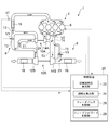
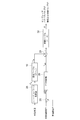
- FIG. 1 is a schematic view showing an entire configuration of a supercharging system (two-stage turbo system) 2 of an internal combustion engine 1 according to an embodiment of the present invention.
- the internal combustion engine 1 is, for example, a four-cylinder diesel engine, and motive power is generated by compression-ignition combustion of the intake air taken in from the intake system 4 with fuel supplied from a common rail (not shown) in the combustion chamber 6. Exhaust gas generated in the combustion chamber 6 is exhausted to the outside through the exhaust system 8. Needless to say, a gasoline engine may be used as the internal combustion engine 1.
- the supercharging system 2 has a first turbocharger 10A and a second turbocharger 10B.
- the first turbocharger 10A includes a turbo compressor 12A and an exhaust turbine 14A.
- the second turbocharger 10B includes a turbo compressor 12B and an exhaust turbine 14B.
- These two turbochargers 10A and 10B are turbochargers of substantially the same turbine capacity, and in the case of the series supercharging mode, the first turbocharger 10A located on the upstream side of the exhaust flow path is The second turbocharger 10B, which functions as a high pressure turbocharger and is located downstream of the exhaust passage, is configured to function as a low pressure turbocharger.
- the intake system 4 includes an intake series flow passage T1 externally connected to the internal combustion engine 1 via the turbo compressor 12A of the first turbocharger 10A and the turbo compressor 12B of the second turbocharger 10B,
- An intake bypass channel T2 is provided, which connects the outlet side of the turbo compressor 12A of the first turbocharger 10A to the outlet side of the turbo compressor 12B of the second turbocharger 10B.
- a compressor bypass valve V1 which is an intake flow path switching valve is provided in the intake bypass flow path T2.
- the compressor bypass valve V1 is a proportional control valve, and the flow rate can be continuously controlled according to the opening degree.
- an intercooler for cooling the charge air that is compressed and heated by the turbocharger is provided.
- a cooler 16 is provided.
- an air cleaner 18 for purifying intake air is provided.
- the exhaust system 8 includes an exhaust serial flow passage T3 from the internal combustion engine 1 to the outside through the exhaust turbine 14B of the second turbocharger 10B and the exhaust turbine 14A of the first turbocharger 10A; An exhaust first bypass passage T4 connecting the inlet side of the exhaust turbine 14B of the second turbocharger 10B and the inlet side of the exhaust turbine 14A of the first turbocharger 10A, and the exhaust first bypass An exhaust second bypass passage T5 connecting the downstream side of the downstream connection point between the flow passage T4 and the exhaust serial passage T3 and the outlet side of the exhaust turbine 14B of the second turbocharger 10B Prepare. Further, an exhaust flow control valve V2 is provided in the first exhaust bypass flow passage T4, and a waste gate valve V3 is provided in the second exhaust bypass flow passage T5.
- the exhaust flow control valve V2 and the waste gate valve V3 are both exhaust switching valves, and as the proportional control valve, the flow can be controlled continuously according to the opening degree.
- a muffler 19 for silencing is provided downstream of the junction 21 on the downstream side of the exhaust serial flow passage T3 and the exhaust second bypass flow passage T5 in the exhaust system 8.
- the supercharging system 1 includes a control device 20 which is a control unit.
- the control device 20 is an arithmetic processing unit, and is constituted of an arithmetic processing device such as a microprocessor, for example.
- the control device 20 is configured to be able to switch the flow paths of the intake system 4 and the exhaust system 8 by controlling the compressor bypass valve V1, the exhaust flow control valve V2 and the waste gate valve V3.
- control device 20 detects the supercharging pressure of the turbocharger, and the target supercharging pressure calculation unit 22 that calculates the target boost pressure based on the operating state in order to perform control described later.
- a feedback control unit 26 feedback-controls a first control index corresponding to the opening degree of the compressor bypass valve V1 and the exhaust flow control valve V2 based on the difference between the feed pressure detection unit 24 and the target additional pressure and the supercharging pressure.
- the feedback control is, for example, PID control.
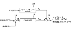
- FIG. 2 is a schematic view showing control logic in the control device 20 of FIG. 1 by functional blocks.
- a first control index ⁇ is introduced for collectively controlling the compressor bypass valve and the exhaust flow control valve.
- the degree of opening of the compressor bypass valve V1 moves, for example, in the range of 0 to 100%.
- ⁇ (0 to 1 as value) is introduced.
- the degree of opening of the exhaust flow control valve V2 moves, for example, in the range of 0 to 100%.
- the relationship between the opening degree of the compressor bypass valve V1, the opening degree of the exhaust flow control valve V2, and ⁇ is as shown in FIG.
- FIG. 3 is a graph showing the relationship between the first control index and the degree of opening of the compressor bypass valve V1 and the exhaust flow control valve V2.
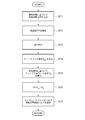
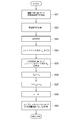
- FIG. 4 is a flowchart showing the control method implemented by the control logic of FIG. 2 in each step.
- the target boost pressure calculation unit 22 obtains a target boost pressure Pt corresponding to the operating state (step S11).
- the operating state is grasped by, for example, the fuel injection amount and the engine rotational speed, and the target boost pressure Pt is determined according to the operating state.
- the target boost pressure Pt also increases as the fuel injection amount and the engine speed increase.
- Such a relationship between the target boost pressure Pt and the operating state is stored in advance as a map (not shown) in a storage device such as a memory, and the target boost pressure Pt can be calculated by reading the map. It is done.
- the supercharging pressure detection unit 24 obtains a detection signal from the supercharging pressure sensor 17 provided downstream of the junction 13 in the intake pipe 4 to obtain the actually measured value of the supercharging pressure (hereinafter referred to as appropriate).
- the “actual boost pressure” P) is acquired (step S12).
- the subtractor 25 acquires the target supercharging pressure Pt determined in step S11 and the actual supercharging pressure P acquired in step S12, and outputs the deviation ⁇ P (step S13).
- the deviation ⁇ P is input to the PID controller 26, and the feedback component ⁇ pid is output by calculation (step S14).
- the first term on the right side is a proportional term
- the second term is an integral term
- the third term is a differential term.
- the coefficients Kp, Ki, and Kd in the above equation may be set by obtaining optimum values from the results of actual control by cut and try. For example, known methods such as step response method and limit sensitivity method are used. be able to.
- a feedforward control unit 28 is provided as an additional element.
- the feedforward control unit 28 acquires a disturbance factor, and outputs a feedforward component ⁇ ff to suppress the fluctuation (turbulation) of the charging pressure caused by the disturbance factor (step S15).
- the compressor bypass valve V1 and the exhaust flow control valve V2 are controlled based on the first control index ⁇ calculated based on the above equation (3) (step S17). As described above, in the present embodiment, by regarding the compressor bypass valve V1 and the exhaust flow control valve V2 as one body for control based on the first control index ⁇ , it is possible to smoothly carry out a plurality of valve controls.
- Example 2 In the first embodiment described above, the compressor bypass valve V1 and the exhaust flow control valve V2 are controlled by outputting the feedback component from the PID control unit 26 as the first control index ⁇ . Since the control index ⁇ has nonlinear characteristics with respect to the supercharging pressure, there is room for improvement in controllability. This can be solved by the second embodiment described below.
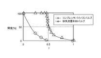
- FIG. 5 is a characteristic graph showing the relationship between the second control index ⁇ and the supercharging pressure P
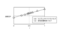
- FIG. 6 is a graph showing the relationship between the second control index ⁇ , the compressor bypass valve V1 and the exhaust flow control valve V2.
- FIG. 7 is a graph showing the relationship between the first control index ⁇ and the second control index ⁇ .
- the round (white) symbol corresponds to the compressor bypass valve V1
- the triangular (white) symbol indicates data corresponding to the exhaust flow control valve V2.
- the feedback output of the PID control unit 26 is output as a second control index ⁇ having a linear characteristic with respect to the charging pressure.
- the second control index ⁇ has a linear characteristic with respect to the supercharging pressure as shown in FIG. Further, as shown in FIG. 6, the second control index ⁇ has a characteristic with respect to the opening degree of the compressor bypass valve V1 and the exhaust flow control valve V2.
- Such second control index ⁇ is configured to be mutually convertible with respect to the above-described first control index ⁇ .
- the conversion table 30 defining the relationship between the first control index ⁇ and the second control index ⁇ is stored in advance in a storage device such as a memory, and read appropriately. It is configured to be possible. Since the conversion equation from the first control index ⁇ having the nonlinear characteristic to the second control index having the linear characteristic is generally complicated, the processing load can be reduced by defining the conversion table 30 in advance in this manner. By reducing the memory capacity and improving the processing speed, good responsiveness can be obtained.
- FIG. 8 is a schematic diagram showing control logic in the control device 20 of the second embodiment in functional blocks
- FIG. 9 is a flowchart showing a control method implemented by the control logic of FIG. Steps S21 to S23 in FIG. 8 are the same as steps S11 to S13 in FIG. 4 (Example 1), and thus redundant description will be omitted.
- the PID controller 26 obtains the deviation ⁇ P output from the subtractor 25 and calculates the feedback component ⁇ pid by calculation (step S24).
- the first term on the right side is a proportional term
- the second term is an integral term
- the third term is a differential term.
- the coefficients kp, ki, and kd in the above equation may be set by obtaining optimum values from the results of actual control by cut and try. For example, known methods such as step response method and limit sensitivity method may be used. be able to.
- the feedforward control unit 28 outputs the feedforward component ⁇ ff generated due to the disturbance factor as in the first embodiment (step S25).
- the feedforward component ⁇ ff is converted into a feedforward component ⁇ ff corresponding to the second control index ⁇ by the conversion table 30 (step S 26), and then added to the feedback component ⁇ pid in the adder 29.
- the second control index ⁇ obtained in this way is converted to the first control index ⁇ using the conversion table 30 (step S 27), and the second control index ⁇ is converted to the first control index ⁇ ( Step S28). Then, the compressor bypass valve V1 and the exhaust flow control valve V1 are controlled based on the first control index ⁇ (step S29).
- the compressor bypass valve V1 and the exhaust flow control valve V2 can be controlled based on the second control index ⁇ having linear characteristics with respect to the supercharging pressure, a plurality of valves can be provided. It can be controlled smoothly with good responsiveness.
- the present disclosure is applicable to a supercharging system of an internal combustion engine that performs supercharging over multiple stages and a control method of the supercharging system.
Landscapes
- Engineering & Computer Science (AREA)
- Chemical & Material Sciences (AREA)
- Combustion & Propulsion (AREA)
- Mechanical Engineering (AREA)
- General Engineering & Computer Science (AREA)
- Supercharger (AREA)
Abstract
Description
例えば、「ある方向に」、「ある方向に沿って」、「平行」、「直交」、「中心」、「同心」或いは「同軸」等の相対的或いは絶対的な配置を表す表現は、厳密にそのような配置を表すのみならず、公差、若しくは、同じ機能が得られる程度の角度や距離をもって相対的に変位している状態も表すものとする。
また例えば、四角形状や円筒形状等の形状を表す表現は、幾何学的に厳密な意味での四角形状や円筒形状等の形状を表すのみならず、同じ効果が得られる範囲で、凹凸部や面取り部等を含む形状も表すものとする。
一方、一の構成要素を「備える」、「具える」、「具備する」、「含む」、又は、「有する」という表現は、他の構成要素の存在を除外する排他的な表現ではない。
内燃機関1は、例えば4気筒ディーゼルエンジンであり、吸気系4から取り込まれた吸気が燃焼室6においてコモンレール(不図示)から供給された燃料と圧縮着火燃焼されることによって、動力が発生する。燃焼室6で生じた排気ガスは、排気系8を介して外部に排出される。
尚、内燃機関1としてガソリンエンジンであってもよいことは言うまでもない。
尚、排気系8のうち排気用直列流路T3と排気用第2バイパス流路T5との下流側の合流地点21より下流側には、消音用のマフラー19が設けられている。
尚、フィードバック制御は例えばPID制御である。
図2は図1の制御装置20における制御ロジックを機能ブロックで示す模式図である。実施例1では、コンプレッサバイパスバルブ及び排気流量制御バルブをまとめて制御するための第1の制御指標θを導入する。コンプレッサバイパスバルブV1の開度は例えば0~100%の範囲で動く。これを標準化するためにθ(値としては0~1)を導入する。排気流量制御バルブV2の開度は例えば0~100%の範囲で動く。これを標準化するためにθ(値としては1~2)を導入する。コンプレッサバイパスバルブV1の開度、排気流量制御バルブV2の開度、θの関係は図3のようになる。
操作量θpid=Kp×偏差+Ki×偏差の累積値+Kd×前回偏差との差 (2)
により行われる。ここで右辺の第1項は比例項であり、第2項は積分項であり、第3項は微分項である。尚、上式における係数Kp、Ki、Kdはカットアンドトライで実際に制御した結果から最適な値を求めることにより設定するとよく、例えばステップ応答法、限界感度法等のような公知の手法を用いることができる。
θ=θpid+θff (3)
によって求められる(ステップS16)。このようにフィードフォワード制御部28を備えることにより、外乱入力に対する応答性が向上する。
上述の実施例1では、PID制御部26からのフィードバック成分を第1の制御指標θとして出力することで、コンプレッサバイパスバルブV1及び排気流量制御バルブV2を制御しているが、一般的に第1の制御指標θは過給圧に対して非線形特性を有するため、制御性に改善の余地が残されている。これは、以下に説明する実施例2によって解消することができる。
尚、図5乃至図7では、丸形状(白抜き)のシンボルはコンプレッサバイパスバルブV1に対応し、三角形状(白抜き)のシンボルは排気流量制御バルブV2に対応したデータをそれぞれ示している。
尚、図8のステップS21乃至S23は、図4(実施例1)のステップS11乃至S13と同様であるため、重複する説明は割愛する。
操作量τpid=kp×偏差+ki×偏差の累積値+kd×前回偏差との差 (4)
により算出される。ここで右辺の第1項は比例項であり、第2項は積分項であり、第3項は微分項である。尚、上式における係数kp、ki、kdはカットアンドトライで実際に制御した結果から最適な値を求めることにより設定するとよく、例えばステップ応答法、限界感度法等のような公知の手法を用いることができる。
τ=τpid+τff (5)
が得られる(ステップS27)。
2 内燃機関(エンジン)
4 吸気系
6 燃焼室
8 排気系
10A 高圧側ターボ過給機
10B 低圧側ターボ過給機
12A 高圧側ターボコンプレッサ
12B 低圧側ターボコンプレッサ
13 合流地点
14A 高圧側排気タービン
14B 低圧側排気タービン
16 インタークーラ
18 エアクリーナ
19 マフラー
20 制御装置
21 合流地点
22 目標過給圧算出部
24 過給圧検出部
25 減算器
26 PID制御部
28 フィードフォワード制御部
29 加算器
30 変換テーブル
Claims (6)
- 内燃機関と、
前記内燃機関からの排気ガスにより駆動される複数のターボ過給機と、
前記内燃機関の吸気流路を切換可能に構成された吸気流路切換弁と、
前記内燃機関の排気流路を切換可能に構成された排気流路切換弁と
前記内燃機関の運転状態に基づいて目標過給圧を算出する目標加給圧算出部と、
前記複数のターボ過給機の過給圧を検出する過給圧検出部と、
前記目標加給圧及び前記過給圧に基づいて算出される前記第1の制御指標に基づいて前記吸気流路切換弁及び前記排気流路切換弁を制御する制御部と
を備え、
前記第1の制御指標は、前記吸気流路切換弁及び前記排気流路切換弁の開度を変数として含む演算式により算出されることを特徴とする内燃機関の過給システム。 - 前記第1の制御指標を前記過給圧に対して線形特性を有する第2の制御指標に変換するための変換テーブルを更に備え、
前記制御部は、前記目標加給圧及び前記過給圧に基づいて算出される前記第2の制御指標を前記変換テーブルによって前記第1の制御指標に変換し、当該第1の制御指標に基づいて前記吸気流路切換弁及び前記排気流路切換弁を制御することを特徴とする請求項1に記載の内燃機関の過給システム。 - 前記第2の制御指標は、該第2の制御指標が増加するに従って、前記吸気流路切換弁の開度が最大値から単調減少した後、前記排気流路切換弁が最大値から単調減少するように規定されることを特徴とする請求項2に記載の内燃機関の過給システム。
- 前記複数のターボ過給機は、
前記吸気流路に設けられた第1のターボコンプレッサ及び前記排気流路に設けられた第1の排気タービンを備える第1のターボ過給機と、
前記吸気流路において前記第1のターボコンプレッサより上流側に設けられた第2のターボコンプレッサ及び前記排気流路において前記第1の排気タービンより下流側に設けられた第2の排気タービンを備える第2のターボ過給機と
を含むことを特徴とする請求項1から3のいずれか1項に記載の内燃機関の過給システム。 - 前記吸気流路は、
外部から前記第1のターボコンプレッサ及び前記第2のターボコンプレッサを介して、前記内燃機関に接続される吸気用直列流路と、
前記第1のターボコンプレッサの出口側を前記第2のターボコンプレッサの出口側に接続する吸気用バイパス流路と
を備え、
前記排気流路は、
前記内燃機関から前記第2の排気タービン及び前記第1の排気タービンを介して外部に至るまでの排気用直列流路と、
前記第2の排気タービンの入口側と前記第1の排気タービンの入口側とを接続する排気用第1バイパス流路と、
前記排気用第1バイパス流路と前記排気用直列流路との下流側の接続ポイントより下流側と前記第2の排気タービンの出口側とを接続する排気用第2バイパス流路と
を備え、
前記吸気流路切換弁は前記吸気用バイパス流路に設けられたコンプレッサバイパスバルブであり、
前記排気用切換弁は前記排気用第1バイパス流路に設けられた排気流量制御バルブであることを特徴とする請求項4に記載の内燃機関の過給システム。 - 内燃機関と、
前記内燃機関からの排気ガスにより駆動される複数のターボ過給機と、
前記内燃機関の吸気流路を切換可能に構成された吸気流路切換弁と、
前記内燃機関の排気流路を切換可能に構成された排気流路切換弁と
を備える内燃機関の過給システムの制御方法であって、
前記内燃機関の運転状態に基づいて目標過給圧を算出する目標加給圧算出工程と、
前記複数のターボ過給機の過給圧を検出する過給圧検出工程と、
前記目標加給圧及び前記過給圧に基づいて算出される前記第1の制御指標に基づいて前記吸気流路切換弁及び前記排気流路切換弁を制御する制御工程と
を備え、
前記第1の制御指標は、前記吸気流路切換弁及び前記排気流路切換弁の開度を変数として含む演算式により算出されることを特徴とする内燃機関の過給システムの制御方法。
Priority Applications (5)
| Application Number | Priority Date | Filing Date | Title |
|---|---|---|---|
| JP2016572965A JP6314255B2 (ja) | 2015-02-02 | 2015-02-02 | 内燃機関の過給システム及び過給システムの制御方法 |
| US15/535,564 US10533490B2 (en) | 2015-02-02 | 2015-02-02 | Supercharging system of internal combustion engine and method of controlling supercharging system |
| PCT/JP2015/052864 WO2016125238A1 (ja) | 2015-02-02 | 2015-02-02 | 内燃機関の過給システム及び過給システムの制御方法 |
| CN201580071277.6A CN107110008B (zh) | 2015-02-02 | 2015-02-02 | 内燃机的增压系统及增压系统的控制方法 |
| EP15881055.6A EP3236042B1 (en) | 2015-02-02 | 2015-02-02 | Supercharging system for internal combustion engine and control method for supercharging system |
Applications Claiming Priority (1)
| Application Number | Priority Date | Filing Date | Title |
|---|---|---|---|
| PCT/JP2015/052864 WO2016125238A1 (ja) | 2015-02-02 | 2015-02-02 | 内燃機関の過給システム及び過給システムの制御方法 |
Publications (1)
| Publication Number | Publication Date |
|---|---|
| WO2016125238A1 true WO2016125238A1 (ja) | 2016-08-11 |
Family
ID=56563603
Family Applications (1)
| Application Number | Title | Priority Date | Filing Date |
|---|---|---|---|
| PCT/JP2015/052864 Ceased WO2016125238A1 (ja) | 2015-02-02 | 2015-02-02 | 内燃機関の過給システム及び過給システムの制御方法 |
Country Status (5)
| Country | Link |
|---|---|
| US (1) | US10533490B2 (ja) |
| EP (1) | EP3236042B1 (ja) |
| JP (1) | JP6314255B2 (ja) |
| CN (1) | CN107110008B (ja) |
| WO (1) | WO2016125238A1 (ja) |
Families Citing this family (3)
| Publication number | Priority date | Publication date | Assignee | Title |
|---|---|---|---|---|
| JP6575554B2 (ja) * | 2017-04-03 | 2019-09-18 | トヨタ自動車株式会社 | 排気タービン発電システムとその制御装置 |
| CN109854394A (zh) * | 2017-11-30 | 2019-06-07 | 中国人民解放军陆军军事交通学院 | 变海拔双vgt二级可调增压控制方法 |
| JP6941652B2 (ja) * | 2019-10-16 | 2021-09-29 | 本田技研工業株式会社 | 過給圧設定装置 |
Citations (4)
| Publication number | Priority date | Publication date | Assignee | Title |
|---|---|---|---|---|
| JPH05288111A (ja) * | 1992-04-03 | 1993-11-02 | Fuji Heavy Ind Ltd | シーケンシャルターボエンジンの空燃比制御方法 |
| JP2010203426A (ja) * | 2009-03-06 | 2010-09-16 | Toyota Motor Corp | 過給機付き内燃機関の制御装置 |
| JP2011099338A (ja) * | 2009-11-04 | 2011-05-19 | Toyota Motor Corp | 内燃機関の制御弁異常判定装置 |
| JP2014015846A (ja) * | 2012-07-05 | 2014-01-30 | Toyota Motor Corp | 過給機付内燃機関の制御装置、過給機付内燃機関を搭載した車両 |
Family Cites Families (13)
| Publication number | Priority date | Publication date | Assignee | Title |
|---|---|---|---|---|
| US4691521A (en) | 1984-04-25 | 1987-09-08 | Nissan Motor Co., Ltd. | Supercharger pressure control system for internal combustion engine with turbocharger |
| JPH0754086B2 (ja) * | 1986-09-12 | 1995-06-07 | 株式会社東芝 | 蒸気加減弁の制御装置 |
| JP2000110571A (ja) * | 1998-10-01 | 2000-04-18 | Mazda Motor Corp | ターボ過給機付エンジンの制御装置 |
| JP2005207234A (ja) * | 2004-01-20 | 2005-08-04 | Denso Corp | エンジン制御システム |
| JP4935094B2 (ja) | 2006-02-02 | 2012-05-23 | いすゞ自動車株式会社 | ディーゼルエンジンの2段式過給システム |
| JP4375387B2 (ja) * | 2006-11-10 | 2009-12-02 | トヨタ自動車株式会社 | 内燃機関 |
| FR2917128B1 (fr) * | 2007-06-05 | 2009-07-31 | Renault Sas | Systeme de regulation de la pression de suralimentation pour moteur a combustion interne a deux turbocompresseurs etages. |
| US7757549B2 (en) | 2008-02-21 | 2010-07-20 | Cummins Ip, Inc | Apparatus, system, and method for predictive control of a turbocharger |
| JP5324961B2 (ja) | 2009-02-27 | 2013-10-23 | 三菱重工業株式会社 | 内燃機関の過給システム |
| US8468821B2 (en) | 2009-11-19 | 2013-06-25 | GM Global Technology Operations LLC | Dual-loop control systems and methods for a sequential turbocharger |
| US8666636B2 (en) * | 2011-01-14 | 2014-03-04 | Toyota Jidosha Kabushiki Kaisha | Control apparatus for internal combustion engine with supercharger |
| JP6377340B2 (ja) * | 2013-12-04 | 2018-08-22 | 三菱重工業株式会社 | 過給システムの制御装置 |
| JP6589932B2 (ja) * | 2017-05-10 | 2019-10-16 | トヨタ自動車株式会社 | 過給機付き内燃機関の制御装置 |
-
2015
- 2015-02-02 US US15/535,564 patent/US10533490B2/en not_active Expired - Fee Related
- 2015-02-02 WO PCT/JP2015/052864 patent/WO2016125238A1/ja not_active Ceased
- 2015-02-02 JP JP2016572965A patent/JP6314255B2/ja active Active
- 2015-02-02 EP EP15881055.6A patent/EP3236042B1/en not_active Not-in-force
- 2015-02-02 CN CN201580071277.6A patent/CN107110008B/zh not_active Expired - Fee Related
Patent Citations (4)
| Publication number | Priority date | Publication date | Assignee | Title |
|---|---|---|---|---|
| JPH05288111A (ja) * | 1992-04-03 | 1993-11-02 | Fuji Heavy Ind Ltd | シーケンシャルターボエンジンの空燃比制御方法 |
| JP2010203426A (ja) * | 2009-03-06 | 2010-09-16 | Toyota Motor Corp | 過給機付き内燃機関の制御装置 |
| JP2011099338A (ja) * | 2009-11-04 | 2011-05-19 | Toyota Motor Corp | 内燃機関の制御弁異常判定装置 |
| JP2014015846A (ja) * | 2012-07-05 | 2014-01-30 | Toyota Motor Corp | 過給機付内燃機関の制御装置、過給機付内燃機関を搭載した車両 |
Also Published As
| Publication number | Publication date |
|---|---|
| EP3236042B1 (en) | 2020-04-01 |
| JPWO2016125238A1 (ja) | 2017-07-06 |
| CN107110008B (zh) | 2019-07-30 |
| US20170356332A1 (en) | 2017-12-14 |
| US10533490B2 (en) | 2020-01-14 |
| EP3236042A1 (en) | 2017-10-25 |
| JP6314255B2 (ja) | 2018-04-18 |
| CN107110008A (zh) | 2017-08-29 |
| EP3236042A4 (en) | 2018-07-18 |
Similar Documents
| Publication | Publication Date | Title |
|---|---|---|
| KR101390542B1 (ko) | 내연기관의 터보과급 시스템 | |
| US8806869B2 (en) | Method for controlling a turbocharger system of an internal combustion engine, and turbocharger system | |
| CN101845986B (zh) | 通过调节涡轮增压器旁通阀和可变几何涡轮机对气道压力极限的基于模型的控制 | |
| JP5018975B2 (ja) | 内燃機関の過給機制御装置 | |
| WO2012057191A1 (ja) | ターボ過給システム | |
| JP2008196332A (ja) | ターボチャージャ付内燃機関の制御装置 | |
| KR102625569B1 (ko) | 배기가스 구동식 과급기의 과급기 액추에이터를 위한 조작 변수를 결정하기 위한 방법 및 장치 | |
| JP4306703B2 (ja) | 過給機付き内燃機関の制御装置 | |
| JP2012229621A (ja) | 内燃機関の制御装置 | |
| CN100476175C (zh) | 在具有两级涡轮增压器的内燃机中的排气控制 | |
| KR101563831B1 (ko) | 내연 기관의 제어 장치 | |
| RU2614050C1 (ru) | Устройство управления для двигателя внутреннего сгорания | |
| JP5035097B2 (ja) | 多段式ターボ過給システムのサージ回避制御システム | |
| JP4835474B2 (ja) | ターボ過給機制御システム | |
| CN111206995B (zh) | 用于控制增压系统的方法 | |
| JP5035275B2 (ja) | 内燃機関の制御装置 | |
| JP6314255B2 (ja) | 内燃機関の過給システム及び過給システムの制御方法 | |
| JP2016130489A (ja) | 内燃機関の制御装置 | |
| US20130060450A1 (en) | Method and device for performing a control, in particular for use in a motor vehicle | |
| JPWO2016129036A1 (ja) | 内燃機関の過給システム及び過給システムの制御方法 | |
| JP2014118883A (ja) | 内燃機関の制御装置 | |
| JP6540659B2 (ja) | 内燃機関の制御システム | |
| JP7159980B2 (ja) | 過給システム | |
| JP5716764B2 (ja) | エンジン制御装置 | |
| JP6019864B2 (ja) | エンジンの制御装置 |
Legal Events
| Date | Code | Title | Description |
|---|---|---|---|
| 121 | Ep: the epo has been informed by wipo that ep was designated in this application |
Ref document number: 15881055 Country of ref document: EP Kind code of ref document: A1 |
|
| ENP | Entry into the national phase |
Ref document number: 2016572965 Country of ref document: JP Kind code of ref document: A |
|
| WWE | Wipo information: entry into national phase |
Ref document number: 15535564 Country of ref document: US |
|
| REEP | Request for entry into the european phase |
Ref document number: 2015881055 Country of ref document: EP |
|
| NENP | Non-entry into the national phase |
Ref country code: DE |