WO2016125296A1 - 植物栽培装置 - Google Patents
植物栽培装置 Download PDFInfo
- Publication number
- WO2016125296A1 WO2016125296A1 PCT/JP2015/053347 JP2015053347W WO2016125296A1 WO 2016125296 A1 WO2016125296 A1 WO 2016125296A1 JP 2015053347 W JP2015053347 W JP 2015053347W WO 2016125296 A1 WO2016125296 A1 WO 2016125296A1
- Authority
- WO
- WIPO (PCT)
- Prior art keywords
- leaf
- medium holding
- culture medium
- leaf support
- plant cultivation
- Prior art date
- Legal status (The legal status is an assumption and is not a legal conclusion. Google has not performed a legal analysis and makes no representation as to the accuracy of the status listed.)
- Ceased
Links
Images


Classifications
-
- A—HUMAN NECESSITIES
- A01—AGRICULTURE; FORESTRY; ANIMAL HUSBANDRY; HUNTING; TRAPPING; FISHING
- A01G—HORTICULTURE; CULTIVATION OF VEGETABLES, FLOWERS, RICE, FRUIT, VINES, HOPS OR SEAWEED; FORESTRY; WATERING
- A01G31/00—Soilless cultivation, e.g. hydroponics
-
- A—HUMAN NECESSITIES
- A01—AGRICULTURE; FORESTRY; ANIMAL HUSBANDRY; HUNTING; TRAPPING; FISHING
- A01G—HORTICULTURE; CULTIVATION OF VEGETABLES, FLOWERS, RICE, FRUIT, VINES, HOPS OR SEAWEED; FORESTRY; WATERING
- A01G9/00—Cultivation in receptacles, forcing-frames or greenhouses; Edging for beds, lawn or the like
- A01G9/02—Receptacles, e.g. flower-pots or boxes; Glasses for cultivating flowers
- A01G9/029—Receptacles for seedlings
- A01G9/0295—Units comprising two or more connected receptacles
-
- A—HUMAN NECESSITIES
- A01—AGRICULTURE; FORESTRY; ANIMAL HUSBANDRY; HUNTING; TRAPPING; FISHING
- A01G—HORTICULTURE; CULTIVATION OF VEGETABLES, FLOWERS, RICE, FRUIT, VINES, HOPS OR SEAWEED; FORESTRY; WATERING
- A01G27/00—Self-acting watering devices, e.g. for flower-pots
- A01G27/005—Reservoirs connected to flower-pots through conduits
-
- A—HUMAN NECESSITIES
- A01—AGRICULTURE; FORESTRY; ANIMAL HUSBANDRY; HUNTING; TRAPPING; FISHING
- A01G—HORTICULTURE; CULTIVATION OF VEGETABLES, FLOWERS, RICE, FRUIT, VINES, HOPS OR SEAWEED; FORESTRY; WATERING
- A01G3/00—Cutting implements specially adapted for horticultural purposes; Delimbing standing trees
-
- A—HUMAN NECESSITIES
- A01—AGRICULTURE; FORESTRY; ANIMAL HUSBANDRY; HUNTING; TRAPPING; FISHING
- A01G—HORTICULTURE; CULTIVATION OF VEGETABLES, FLOWERS, RICE, FRUIT, VINES, HOPS OR SEAWEED; FORESTRY; WATERING
- A01G31/00—Soilless cultivation, e.g. hydroponics
- A01G31/02—Special apparatus therefor
- A01G31/04—Hydroponic culture on conveyors
-
- A—HUMAN NECESSITIES
- A01—AGRICULTURE; FORESTRY; ANIMAL HUSBANDRY; HUNTING; TRAPPING; FISHING
- A01G—HORTICULTURE; CULTIVATION OF VEGETABLES, FLOWERS, RICE, FRUIT, VINES, HOPS OR SEAWEED; FORESTRY; WATERING
- A01G7/00—Botany in general
- A01G7/04—Electric or magnetic or acoustic treatment of plants for promoting growth
- A01G7/045—Electric or magnetic or acoustic treatment of plants for promoting growth with electric lighting
-
- A—HUMAN NECESSITIES
- A01—AGRICULTURE; FORESTRY; ANIMAL HUSBANDRY; HUNTING; TRAPPING; FISHING
- A01G—HORTICULTURE; CULTIVATION OF VEGETABLES, FLOWERS, RICE, FRUIT, VINES, HOPS OR SEAWEED; FORESTRY; WATERING
- A01G9/00—Cultivation in receptacles, forcing-frames or greenhouses; Edging for beds, lawn or the like
- A01G9/12—Supports for plants; Trellis for strawberries or the like
-
- A—HUMAN NECESSITIES
- A01—AGRICULTURE; FORESTRY; ANIMAL HUSBANDRY; HUNTING; TRAPPING; FISHING
- A01G—HORTICULTURE; CULTIVATION OF VEGETABLES, FLOWERS, RICE, FRUIT, VINES, HOPS OR SEAWEED; FORESTRY; WATERING
- A01G9/00—Cultivation in receptacles, forcing-frames or greenhouses; Edging for beds, lawn or the like
- A01G9/24—Devices or systems for heating, ventilating, regulating temperature, illuminating, or watering, in greenhouses, forcing-frames, or the like
- A01G9/249—Lighting means
-
- Y—GENERAL TAGGING OF NEW TECHNOLOGICAL DEVELOPMENTS; GENERAL TAGGING OF CROSS-SECTIONAL TECHNOLOGIES SPANNING OVER SEVERAL SECTIONS OF THE IPC; TECHNICAL SUBJECTS COVERED BY FORMER USPC CROSS-REFERENCE ART COLLECTIONS [XRACs] AND DIGESTS
- Y02—TECHNOLOGIES OR APPLICATIONS FOR MITIGATION OR ADAPTATION AGAINST CLIMATE CHANGE
- Y02P—CLIMATE CHANGE MITIGATION TECHNOLOGIES IN THE PRODUCTION OR PROCESSING OF GOODS
- Y02P60/00—Technologies relating to agriculture, livestock or agroalimentary industries
- Y02P60/20—Reduction of greenhouse gas [GHG] emissions in agriculture, e.g. CO2
- Y02P60/21—Dinitrogen oxide [N2O], e.g. using aquaponics, hydroponics or efficiency measures
Definitions
- the present invention relates to a plant cultivation apparatus.
- Patent Document 2 describes moving in one direction as the plant grows. That is, seeds or seedlings are located on the upstream side in the moving direction of the plant, and fully grown plants are located on the downstream side in the moving direction. Moreover, it positions so that the space
- Patent Document 3 it is described that the light source changes the height as the plant grows. Further, Patent Document 4 discloses a protective member for growing plant flower buds straightly upward.
- leafy plants such as lettuce
- An object of the present invention is to provide a plant cultivation apparatus that can improve the workability of cutting the root of a leaf.
- the plant cultivation apparatus is a plant cultivation apparatus for obtaining a leaf part by cutting the root of a leaf part from the root part in a grown plant, forming a flow path for circulating a culture solution, and an upper surface
- a flow path member having a plurality of through-holes formed at predetermined intervals along the flow path, a seedling culture medium in which seeds of the plant are arranged, a cylindrical shape, and containing the seedling culture medium
- a medium holding part that is disposed in the through hole of the flow path member and absorbs the culture solution into the seedling culture medium, and is formed in a cylindrical shape, provided on the upper side of the medium holding part, from the seed
- a leaf support portion that supports the grown leaf portion from the periphery.
- the culture medium holding part and the leaf support part are formed so that a blade used for separation of the seedling culture medium and the leaf part can be inserted from the outside at the boundary between the culture medium holding part and the leaf support part.
- the plant cultivation apparatus can suppress drooping of the grown leaves by including a cylindrical leaf support portion. Furthermore, the leaf support part and the culture medium holding part are formed so that a blade used for separating the seedling culture medium and the leaf part can be inserted from the outside at the boundary between the culture medium holding part and the leaf support part. Therefore, the workability of cutting the leaf portion from the root portion is improved while suppressing the drooping of the leaf.
- FIG. 1 is a view when the lighting device is omitted.
- FIG. 2 is a sectional view taken along line 2-2 of FIG. It is the figure which looked at the plant cultivation apparatus of FIG. 1 from the right. It is a figure which shows the state conveyed by the conveyance mechanism from the state of FIG. In the plant at the time of completion
- the leaf part is the state supported by the leaf support part. It is a figure which shows the state which took out the cut
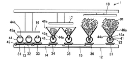
- the plant cultivation apparatus 1 includes a pair of rails 11 and 12, a transport mechanism 13-15, an illumination device 16-18, a culture solution supply unit 21, a culture solution as previously installed parts.
- a recovery unit 22 is provided.
- the plant cultivation apparatus 1 includes a transport unit 31-37 for holding a plant as a moving body. The transport units 31-37 are sequentially moved in the transport direction.
- the pair of rails 11 and 12 are provided in parallel so as to extend in the moving direction of the transport units 31-37 (the arrow direction in FIG. 1).
- the pair of rails 11 and 12 serve as guides for transporting the transport units 31-37.
- the transport mechanism 13-15 is disposed between the pair of rails 11 and 12 as shown in FIGS. 2 and 4, and moves the transport unit 31-37 in the transport direction.
- the first transport mechanism 13 transports the transport units 31 and 32 to the next position.
- the second transport mechanism 14 is arranged in series downstream of the first transport mechanism 13 in the transport direction.
- the second transport mechanism 14 transports the transport units 33 and 34 to the next position.
- the third transport mechanism 15 is arranged in series downstream of the second transport mechanism 14 in the transport direction.
- the third transport mechanism 15 transports the transport units 35-37 to the next position.
- the transport mechanism 13-15 is configured as a so-called one-way clutch so that the state shown in FIG. 4 can be returned to the state shown in FIG.
- the transport distance by the transport mechanism 13-15 becomes longer in the order of the first transport mechanism 13, the second transport mechanism 14, and the third transport mechanism 15. That is, the distance between adjacent transport units 31-33 is the shortest, the distance between adjacent transport units 33-35 is the next shortest, and the distance between adjacent transport units 35-37 is the longest. In this way, the transport mechanism 13-15 transports the transport unit 31-37 so as to change the distance between the adjacent transport units 31-37.
- the lighting device 16-18 gives light to the plants held in the transport unit 31-37 to be transported.
- the installation heights of the illumination devices 16-18 are different.
- the first lighting device 16 is provided at a position corresponding to the transport units 31-33, and is provided at the lowest position.
- the second illumination device 17 is provided at a position corresponding to the transport units 34 and 35 and is provided at a position higher than the first illumination device 16.
- the third lighting device 18 is provided at a position corresponding to the transport units 36 and 37 and is provided at a position higher than the second lighting device 17.
- the culture solution supply unit 21 is provided on one of the outer sides (lower side in FIG. 1) of the pair of rails 11 and 12 facing each other (up and down direction in FIG. 1), and constitutes each of the positioned transport units 31-37.
- the culture solution is supplied to the flow path member 41 that performs the operation.
- the culture medium recovery unit 22 is provided on the other outer side (upper side in FIG. 1) of the pair of rails 11 and 12 in the opposing direction, and is discharged from the flow path member 41 constituting each of the positioned transport units 31-37. Collect the culture medium.
- Each of the transport units 34-37 includes a channel member 41, support members 42, 43, a seedling culture medium 44a-44c, a medium holding part 45a-45c, and a leaf support part 46a-46c.
- the flow path member 41 is formed in a cylindrical shape and forms a flow path through which the culture solution is circulated.
- the flow path member 41 has a circular cylindrical shape, but is not limited thereto, and may be, for example, a rectangular cylindrical shape.
- a plurality of through holes 41a-41c are formed on the upper surface of the flow path member 41 at predetermined intervals along the flow path.
- the through holes 41a-41c are circular holes.
- On the upper surface of one end of the flow path member 41 a hole for allowing the culture solution supplied from the culture solution supply unit 21 to flow is formed.
- a through hole (not shown) for discharging the culture medium to the culture medium recovery unit 22 is formed on the other end surface of the flow path member 41. The culture solution flows from one end of the flow path member 41 toward the other end.
- the support members 42 and 43 are provided on the lower surface of the flow path member 41 and are located at positions corresponding to the pair of rails 11 and 12.
- the support member 42 moves on the pair of rails 11 and 12. Further, the support member 42 is locked in the transport direction by the transport mechanism 13-15, and moves with the operation of the transport mechanism 13-15. That is, when the support members 42 and 43 move in the transport direction, the flow path member 41 moves in the transport direction.
- the seedling medium 44a-44c is arranged with plant seeds.
- the seedling culture media 44a to 44c are formed in a columnar shape.
- the seedling culture media 44a-44c are formed of a material that absorbs the culture solution flowing through the inside of the flow path member 41.
- the culture medium holding parts 45a to 45c are formed in a cylindrical shape by, for example, PP resin or PET resin.
- the culture medium holding parts 45a to 45c are formed to have a flexible film thickness, for example, several mm.
- the medium holding units 45a-45c store and hold the seedling-raising medium 44a-44c.
- the culture medium holding portions 45a to 45c are disposed in the through holes 41a to 41c of the flow path member 41. At this time, a part of the culture medium holding part 45a-45c protrudes upward from the through hole 41a-41c.
- the remaining part of the culture medium holding parts 45 a to 45 c is immersed in the culture solution flowing through the flow path member 41. Therefore, the medium holding parts 45a-45c are located at positions where the culture medium 44a-44c absorbs the culture solution.
- the leaf support portions 46a-46c are formed in a cylindrical shape by, for example, PP resin or PET resin.
- the leaf support portions 46a-46c are provided above the culture medium holding portions 45a-45c.
- the upper opening of the leaf support portions 46a-46c is formed larger than the lower opening.
- the leaf support portions 46a-46c are formed separately from the medium holding portions 45a-45c, and are detachably provided on the medium holding portions 45a-45c.
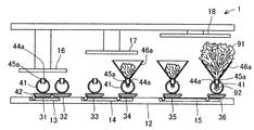
- the leaf support portions 46a to 46c support the leaf portion 91 grown from the seed from the periphery. That is, the leaf support portions 46a to 46c suppress the drooping of the leaf portion 91.
- the leaf support portions 46a to 46c are formed in a tapered cylindrical shape.
- the leaf support portions 46a-46c are provided on the culture medium holding portions 45a-45c so that the small diameter opening portion faces downward.
- the tapered cylindrical small-diameter opening part side of the leaf support parts 46a-46c is connected to the upper opening edge of the culture medium holding part 45a-45c.
- the transport unit 31-33 located on the upstream side in the transport direction has a configuration in which the leaf support portions 46a-46c are removed from the transport unit 34-37 described above. That is, the leaf support portions 46a-46c are attached when the leaf portion 91 of the plant begins to grow.
- the transport units 31-33 are close to each other in the transport direction because the leaf support portions 46a-46c are not attached.
- the transport units 34-37 located on the downstream side in the transport direction have a positional relationship apart in the transport direction because the leaf support portions 46a-46c are attached.
- the transport units 36 and 37 are so large that the leaf portion 91 grows beyond the leaf support portions 46a to 46c, and therefore, the transport units 36 and 37 have a positional relationship that is larger than the separation distance of the transport units 34 and 35.
- the first lighting device 16 corresponding to the transport unit 31-33 is located at a position closest to the seedling culture medium 44a-44c before the leaf support parts 46a-46c are attached to the medium holding parts 45a-45c.
- the second lighting device 17 corresponding to the transport units 34 and 35 has the height of the leaf support portions 46a to 46c in the state where the leaf support portions 46a to 46c are attached to the culture medium holding portions 45a to 45c.
- Light is applied at a position far from -44c.
- the third lighting device 18 corresponding to the transport units 36 and 37 provides light at a position farthest from the seedling culture medium 44a-44c in a state where the leaf support sections 46a-46c are mounted on the culture medium holding sections 45a-45c. . That is, the lighting devices 16-18 are provided at a height corresponding to the height of plant growth.
- the operator uses the blade 50 to separate the seedling culture medium 44 and the leaf portion 91 from each other. Specifically, the operator lifts the leaf support portion 46 upward and separates the leaf support portion 46 from the upper edge of the culture medium holding portion 45. That is, the leaf support part 46 is in a state of supporting the leaf part 91 and detaching from the culture medium holding part 45 to form a gap with the culture medium holding part 45. In this state, the operator can insert the blade 50 from the outside at the boundary between the culture medium holding part 45 and the leaf support part 46. The operator cuts the root of the leaf portion 91 from the root portion 92 present in the seedling culture medium 44. Then, as shown in FIG. 5B, the leaf portion 91 is in a free state with respect to the root portion 92 and is held by the leaf support portion 46.
- the culture medium holding part 45 and the leaf support part 46 are separated from each other over the entire circumference, the operability of the blade 50 is improved and the root of the leaf part 91 is easily cut. That is, the medium holding part 45 and the leaf support part 46 are detachably provided, so that the blade 50 can be inserted from the outside at the boundary between the medium holding part 45 and the leaf support part 46.
- the worker can transport the leaf portion 91 to another place in a state where the leaf portion 91 is supported by the leaf support portion 46. That is, the leaf support portion 46 functions as a transport protection member that protects the leaf portion 91 when the cut leaf portion 91 is transported.
- the leaf support portion 46 as a transport protection member is effective in hygiene management.
- the leaf support part 46 as a conveyance protection member is removed from the leaf part 91, and only the leaf part 91 of a plant is obtained as shown in FIG. 5C.
- the obtained leaf portion 91 is packaged with a packaging material and shipped, for example.
- the culture medium holding part 45 and the leaf support part 46 are provided separately and detachably, the culture medium holding part 45 and the leaf support part 46 are integrally formed, and the culture medium holding part 45 is provided.
- a hole (slit) penetrating from the outside toward the inside may be formed at the boundary between the leaf support portion 46 and the leaf support portion 46. In this case, the operator inserts the blade 50 from the outside of the hole portion and cuts the root of the leaf portion 91 existing inside.
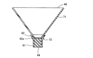
- the culture medium holding part 45 includes a cylindrical part 61 that penetrates and a flange part 62 that expands from the upper end of the cylindrical part 61.
- the cylinder part 61 is formed in a cylindrical shape.
- the cylinder portion 61 holds the seedling culture medium 44.
- the flange part 62 is formed in the shape of an inverted cone projecting radially outward and upward. More specifically, the flange portion 62 is formed in a tapered cylindrical shape.
- the flange portion 62 engages with the upper opening edge of the through holes 41a-41c (shown in FIG. 1) of the flow path member 41.
- a plurality of positioning holes 62a are formed in the flange portion 62 at equal intervals in the circumferential direction.
- Each positioning hole 62a is formed in a rectangular shape.
- a slit 62b is formed so as to extend in the circumferential direction from the lower end of each positioning hole 62a.
- the culture medium holding part 45 is formed by press molding a resin.
- the leaf support portion 46 includes a cylindrical portion 71 that penetrates and a locking claw 72 that protrudes radially outward from the lower end of the cylindrical portion 71.
- the leaf support portion 46 includes a plurality of locking claws 72 formed at equal intervals in the circumferential direction. Each locking claw 72 is formed at a position corresponding to each positioning hole 62a.
- each locking claw 72 causes each locking claw 72 to enter each positioning hole 62a from above. Then, each locking claw 72 is placed on the lower edge of each positioning hole 62a. Subsequently, the operator rotates the leaf support unit 46 relative to the culture medium holding unit 45. Then, each latching claw 72 enters each slit 62b from each positioning hole 62a. Therefore, the leaf support portion 46 is positioned on the culture medium holding portion 45. Further, the leaf support part 46 is detached from the culture medium holding part 45 when the worker rotates the leaf support part 46 relative to the culture medium holding part 45 in the opposite direction.
- the plant cultivation apparatus 1 in this embodiment obtains the leaf portion 91 by cutting the root of the leaf portion 91 from the root portion 92 in the grown plant.
- the plant cultivation apparatus 1 includes a flow path member 41 having a flow path through which a culture solution is circulated and having a plurality of through holes 41a-41c formed on the upper surface at predetermined intervals along the flow path.
- a seedling culture medium 44a-44c formed in a cylindrical shape, containing and holding the seedling culture medium 44a-44c, disposed in the through holes 41a-41c of the flow path member 41, and raising the culture solution Medium holders 45, 45a-45c to be absorbed by the culture mediums 44, 44a-44c, and a cylindrical shape, provided above the culture medium holders 45, 45a-45c, and supporting the leaf portion 91 grown from seeds from the surroundings Leaf support portions 46, 46a-46c.
- the medium holding parts 45, 45a-45c and the leaf support parts 46, 46a-46c are used for separating the blade 50 used for separating the seedling culture mediums 44, 44a-44c and the leaf part 91 from the medium holding parts 45, 45a-45c and the leaf support. It is formed so as to be insertable from the outside at the boundary between the portions 46 and 46a-46c.
- the leaf support portions 46, 46a-46c By providing the cylindrical leaf support portions 46, 46a-46c, it is possible to prevent the grown leaves from drooping. Further, the leaf support portions 46, 46a-46c and the medium holding portions 45, 45a-45c are used to separate the blade 50 used for separating the seedling culture media 44, 44a-44c and the leaf portion 91 from the medium holding portions 45, 45a-45c. It is formed so that it can be inserted from the outside at the boundary between the leaf support portions 46 and 46a-46c. Therefore, the workability of cutting the leaf portion 91 from the root portion 92 is improved while suppressing the drooping of the leaf.
- the leaf support portions 46, 46a-46c are formed separately from the medium holding portions 45, 45a-45c, are detachably provided on the medium holding portions 45, 45a-45c, and the leaf support portions 46, 46a.
- -46c supports the leaf portion 91 and is detached from the medium holding portions 45, 45a-45c to form a gap between the medium holding portions 45, 45a-45c, and the blade 50 is inserted from the outside at the boundary portion It is possible. Since the culture medium holding part 45, 45a-45c and the leaf support part 46, 46a-46c are separated from each other over the entire circumference, the operability of the blade 50 is improved and the root of the leaf part 91 can be easily cut. Become.
- the leaf support portions 46, 46a-46c are formed in a tapered cylindrical shape, and the small diameter opening side of the tapered cylindrical shape is connected to the culture medium holding portions 45, 45a-45c. It is suppressed reliably that the leaf part 91 of a plant droops. Further, the operator can bring the blade 50 closer to the root of the leaf portion 91 when cutting the root of the leaf portion 91. Therefore, the workability of cutting by the operator is very good.
- One of the leaf support portions 46, 46a-46c and the culture medium holding portions 45, 45a-45c is a locking claw that is locked to the other of the leaf support portions 46, 46a-46c and the culture medium holding portions 45, 45a-45c. 72.
- the engaging claw 72 By the engaging claw 72, the leaf support portions 46, 46a-46c and the culture medium holding portions 45, 45a-45c are configured to be easily detachable.
- the leaf support portions 46, 46a-46c include a cylindrical portion 71, and locking claws 72 that protrude radially outward from the lower end of the cylindrical portion 71 and are locked to the culture medium holding portions 45, 45a-45c.
- the culture medium holding portions 45 and 45a to 45c include a cylindrical portion 61 and an inverted conical flange portion 62 that protrudes radially outward from the upper end of the cylindrical portion 61.
- the flange portion 62 is formed so as to extend in the circumferential direction from the positioning hole 62a formed at a position corresponding to the locking claw 72, and the leaf support portions 46, 46a-46c are connected to the culture medium holding portions 45, 45a.
- the leaf support portions 46, 46a-46c and the culture medium holding portions 45, 45a-45c are configured to be easily detachable.
- the flange portion 62 engages with the upper opening edge of the through holes 41a-41c of the flow path member 41. That is, the flange portion 62 has a connecting function with the leaf support portions 46 and 46a-46c and an engaging function with the upper opening edge of the through holes 41a-41c of the flow path member 41.
- the leaf support portions 46 and 46a to 46c function as a transport protection member that protects the leaf portion 91 when the cut leaf portion 91 is transported. Since the worker does not directly touch the leaf portion 91 of the plant, the leaf support portion 46 as a transport protection member is effective in hygiene management.
- the plant cultivation apparatus 1 includes an illumination device 16-18 that applies light from the upper side of the seedling culture media 44, 44a-44c.
- the lighting device 16-18 gives light at a position close to the seedling culture mediums 44, 44a-44c in a state before the leaf support parts 46, 46a-46c are attached to the culture medium holding parts 45, 45a-45c, In a state where the leaf support portions 46 and 46a to 46c are attached to the culture medium holding portions 45 and 45a to 45c, light is applied at positions far from the seedling culture media 44 and 44a to 44c. Since light is imparted to the plant at a position corresponding to the growth state, the growth of the leaf portion 91 of the plant is short-term.
- the culture medium holding parts 45, 45a-45c and the leaf support parts 46, 46a-46c are made of resin and are formed to have a flexible film thickness. The force applied to the leaf portion 91 of the plant by the leaf support portions 46 and 46a to 46c can be reduced. In addition, it becomes easy for the operator to connect and disconnect the leaf support portions 46, 46a-46c to the culture medium holding portions 45, 45a-45c.
- the leaf support portions 46, 46a-46c are integrally formed with the medium holding portions 45, 45a-45c, and have holes that penetrate from the outside toward the inside at the boundary with the medium holding portions 45, 45a-45c. .
- the workability of cutting the leaf portion 91 from the root portion 92 is sufficiently good while suppressing the drooping of the leaf.
Landscapes
- Life Sciences & Earth Sciences (AREA)
- Environmental Sciences (AREA)
- Biodiversity & Conservation Biology (AREA)
- Ecology (AREA)
- Forests & Forestry (AREA)
- Botany (AREA)
- Engineering & Computer Science (AREA)
- Water Supply & Treatment (AREA)
- Hydroponics (AREA)
- Cultivation Of Plants (AREA)
- Cultivation Receptacles Or Flower-Pots, Or Pots For Seedlings (AREA)
- Supports For Plants (AREA)
Abstract
Description
植物栽培装置1の全体構成について、図1-図4を参照して説明する。図1及び図2に示す植物栽培装置1において、搬送ユニット31-37が図の左から右に向かって(図1の矢印方向に)搬送される。作業者は、図の左側にて新たな搬送ユニット31を投入し、図の右側にて搬送ユニット37を回収する。
搬送ユニット34-37のそれぞれは、流路部材41、支持部材42,43、育苗培地44a-44c、培地保持部45a-45c、及び、葉支持部46a-46cを備える。
次に、植物が生育した後における作業者による処理について、図5A-図5Cを参照して説明する。図5Aに示すように、植物の葉部91は、葉支持部46の上側開口部よりもさらに上側へ飛び出すほどに生育する。
次に、培地保持部45及び葉支持部46の詳細構成について説明する。まず、培地保持部45について、図6A-図6Cを参照して説明する。培地保持部45は、貫通する筒部61と、筒部61の上端から拡開するフランジ部62とを備える。本実施形態においては、筒部61は、円筒状に形成される。筒部61は、育苗培地44を保持する。また、フランジ部62は、径方向外方且つ上側に張り出す逆錐状に形成される。より詳細には、フランジ部62は、テーパ筒状に形成される。フランジ部62は、流路部材41の貫通穴41a-41c(図1に示す)の上側開口縁に係合する。フランジ部62には、周方向に等間隔に複数の位置決め穴62aが形成される。各位置決め穴62aは、矩形に形成される。さらに、各位置決め穴62aの下端から周方向に延びるようにスリット62bが形成される。培地保持部45は、樹脂をプレス成形することにより形成される。
本実施形態における植物栽培装置1は、生育させた植物において葉部91の根元を根部92から切断して葉部91を得る。植物栽培装置1は、培養液を流通させる流路を形成し、且つ、上面に流路に沿って所定間隔ごとに複数の貫通穴41a-41cが形成された流路部材41と、植物の種子が配置される育苗倍地44a-44cと、筒状に形成され、育苗培地44a-44cを収容して保持し、流路部材41の貫通穴41a-41cに配置され、且つ、培養液を育苗培地44,44a-44cに吸収させる培地保持部45,45a-45cと、筒状に形成され、培地保持部45,45a-45cの上側に設けられ、種子から生長した葉部91を周囲から支持する葉支持部46,46a-46cとを備える。
Claims (10)
- 生育させた植物において葉部の根元を根部から切断して前記葉部を得る植物栽培装置であって、
培養液を流通させる流路を形成し、且つ、上面に前記流路に沿って所定間隔ごとに複数の貫通穴が形成された流路部材と、
前記植物の種子が配置される育苗倍地と、
筒状に形成され、前記育苗培地を収容して保持し、前記流路部材の貫通穴に配置され、且つ、前記培養液を前記育苗培地に吸収させる培地保持部と、
筒状に形成され、前記培地保持部の上側に設けられ、前記種子から生長した前記葉部を周囲から支持する葉支持部と、
を備え、
前記培地保持部及び前記葉支持部は、前記育苗培地と前記葉部との分離に用いる刃物を、前記培地保持部と前記葉支持部との境界部において外側から挿入可能に形成される、植物栽培装置。 - 前記葉支持部は、前記培地保持部と別体に形成され、前記培地保持部に着脱可能に設けられ、並びに、前記葉支持部が前記葉部を支持し且つ前記培地保持部から離脱して前記培地保持部との間に隙間を形成する状態において、前記刃物を前記境界部において外側から挿入可能とされる、請求項1に記載の植物栽培装置。
- 前記葉支持部は、テーパ筒状に形成され、前記テーパ筒状の小径開口部側を前記培地保持部に連結される、請求項2に記載の植物栽培装置。
- 前記葉支持部及び前記培地保持部の一方は、前記葉支持部及び前記培地保持部の他方に係止される係止爪を備える、請求項2又は3に記載の植物栽培装置。
- 前記葉支持部は、筒部と、前記筒部の下端から径方向外方に突出し前記培地保持部に係止される前記係止爪とを備え、
前記培地保持部は、筒部と、前記筒部の上端から径方向外方に張り出す逆錐状のフランジ部とを備え、
前記フランジ部は、
前記係止爪に対応する位置に形成される位置決め穴と、
前記位置決め穴から周方向に延びるように形成され、前記葉支持部を前記培地保持部に対して軸線回りに相対回転させることにより前記係止爪を前記位置決め穴から進入させるスリットと、
を備える、請求項4に記載の植物栽培装置。 - 前記フランジ部は、前記流路部材の貫通穴の上側開口縁に係合する、請求項5に記載の植物栽培装置。
- 前記葉支持部は、切断された前記葉部の搬送時において前記葉部を保護する搬送保護部材である、請求項2-6の何れか一項に記載の植物栽培装置。
- 前記植物栽培装置は、前記育苗培地の上側から光を付与する照明装置を備え、
前記照明装置は、
前記葉支持部が前記培地保持部に装着される前の状態において、前記育苗培地に近い位置にて光を付与し、
前記葉支持部が前記培地保持部に装着された状態において、前記育苗培地から遠い位置にて光を付与する、請求項2-7の何れか一項に記載の植物栽培装置。 - 前記葉支持部は、前記培地保持部に一体形成され、前記培地保持部との境界部に外側から内側に向かって貫通する穴部を有する、請求項1に記載の植物栽培装置。
- 前記培地保持部及び前記葉支持部は、樹脂製であり可撓性を有する膜厚に形成される、請求項1-9の何れか一項に記載の植物栽培装置。
Priority Applications (9)
| Application Number | Priority Date | Filing Date | Title |
|---|---|---|---|
| RU2017130743A RU2670163C1 (ru) | 2015-02-06 | 2015-02-06 | Устройство для выращивания растений |
| AU2015381089A AU2015381089B2 (en) | 2015-02-06 | 2015-02-06 | Plant cultivation device |
| SG11201706259XA SG11201706259XA (en) | 2015-02-06 | 2015-02-06 | Plant cultivation device |
| MYPI2017702838A MY184713A (en) | 2015-02-06 | 2015-02-06 | Plant cultivation device |
| JP2016573152A JP6480961B2 (ja) | 2015-02-06 | 2015-02-06 | 植物栽培装置 |
| PCT/JP2015/053347 WO2016125296A1 (ja) | 2015-02-06 | 2015-02-06 | 植物栽培装置 |
| US15/548,528 US10912261B2 (en) | 2015-02-06 | 2015-02-06 | Plant cultivation device |
| CN201580075284.3A CN107205348B (zh) | 2015-02-06 | 2015-02-06 | 植物栽培装置 |
| EP15881113.3A EP3254556B1 (en) | 2015-02-06 | 2015-02-06 | Plant cultivation device |
Applications Claiming Priority (1)
| Application Number | Priority Date | Filing Date | Title |
|---|---|---|---|
| PCT/JP2015/053347 WO2016125296A1 (ja) | 2015-02-06 | 2015-02-06 | 植物栽培装置 |
Publications (1)
| Publication Number | Publication Date |
|---|---|
| WO2016125296A1 true WO2016125296A1 (ja) | 2016-08-11 |
Family
ID=56563660
Family Applications (1)
| Application Number | Title | Priority Date | Filing Date |
|---|---|---|---|
| PCT/JP2015/053347 Ceased WO2016125296A1 (ja) | 2015-02-06 | 2015-02-06 | 植物栽培装置 |
Country Status (9)
| Country | Link |
|---|---|
| US (1) | US10912261B2 (ja) |
| EP (1) | EP3254556B1 (ja) |
| JP (1) | JP6480961B2 (ja) |
| CN (1) | CN107205348B (ja) |
| AU (1) | AU2015381089B2 (ja) |
| MY (1) | MY184713A (ja) |
| RU (1) | RU2670163C1 (ja) |
| SG (1) | SG11201706259XA (ja) |
| WO (1) | WO2016125296A1 (ja) |
Cited By (3)
| Publication number | Priority date | Publication date | Assignee | Title |
|---|---|---|---|---|
| CN106416990A (zh) * | 2016-09-23 | 2017-02-22 | 福建省农业科学院科技干部培训中心 | 一种工厂化水培蔬菜装置及其工作方法 |
| US20180325054A1 (en) * | 2015-06-30 | 2018-11-15 | Green Production Systems Bvba | Cultivation system |
| CN114711057A (zh) * | 2022-04-11 | 2022-07-08 | 杨钰鸿 | 一种农业用育苗装置 |
Families Citing this family (9)
| Publication number | Priority date | Publication date | Assignee | Title |
|---|---|---|---|---|
| EP3259984A4 (en) * | 2015-02-18 | 2018-02-28 | Fuji Seiko Co., Ltd. | Plant cultivation equipment |
| US20190259108A1 (en) * | 2018-02-20 | 2019-08-22 | Osram Gmbh | Controlled Agricultural Systems and Methods of Managing Agricultural Systems |
| CN108901806B (zh) * | 2018-07-11 | 2020-10-27 | 福建省中科生物股份有限公司 | 一种植物水培装置及植物水培方法 |
| CN109169023B (zh) * | 2018-10-22 | 2021-03-02 | 北京工业大学 | 一种自动化蔬菜培育的流水线 |
| CN109328729A (zh) * | 2018-10-28 | 2019-02-15 | 北京工业大学 | 一种对向移动农业作物种植循环流水线 |
| TWI719451B (zh) * | 2019-04-18 | 2021-02-21 | 邱鈺礎 | 植株槽生產設備及植株槽傳送機構 |
| IT201900006823A1 (it) * | 2019-05-14 | 2020-11-14 | Nicola Triolone | Dispositivo e metodo di trasformazione di fiori |
| WO2021257746A1 (en) * | 2020-06-17 | 2021-12-23 | SynchroSystems, Inc. | Container gardening structures and management thereof |
| JP7108979B2 (ja) * | 2020-09-14 | 2022-07-29 | 株式会社安川電機 | 植物栽培システム及び植物栽培方法 |
Citations (7)
| Publication number | Priority date | Publication date | Assignee | Title |
|---|---|---|---|---|
| JPS6255029A (ja) * | 1985-09-04 | 1987-03-10 | 三菱電機株式会社 | 植物栽培装置 |
| JPS63240731A (ja) * | 1987-03-28 | 1988-10-06 | 高柳 栄夫 | 植物栽培方法および植物栽培装置 |
| JPH11155373A (ja) * | 1997-11-21 | 1999-06-15 | Et Harvest:Kk | 植物栽培方法及び装置 |
| JP2001095383A (ja) * | 1999-10-04 | 2001-04-10 | Cosmo Plant Kk | 植物の栽培装置 |
| WO2002003777A1 (en) * | 2000-07-07 | 2002-01-17 | Cosmo Plant Co.,Ltd | Method of producing plants, plant cultivating device, and light-emitting panel |
| JP2003265048A (ja) * | 2002-03-14 | 2003-09-24 | Kaneya Sangyo Kk | 植物の花芽等の育成保護方法及びその保護部材 |
| JP2013201984A (ja) * | 2012-03-28 | 2013-10-07 | Kobe Univ | 軟白部を有する葉菜類の生産方法 |
Family Cites Families (17)
| Publication number | Priority date | Publication date | Assignee | Title |
|---|---|---|---|---|
| US3058263A (en) * | 1960-07-14 | 1962-10-16 | Alfred O Reynolds | Plant grower assembly |
| US4369598A (en) * | 1981-03-19 | 1983-01-25 | Beckwith Thomas F | Container element combination for seed sprouting or plant culture |
| US4476651A (en) * | 1983-01-27 | 1984-10-16 | Geoffrey Drury | Apparatus and method for transporting growing plants |
| US4669217A (en) * | 1984-11-17 | 1987-06-02 | Aeroponics, Associates-1983 Ltd. | Plant propagation system and apparatus |
| DE3602035A1 (de) | 1985-01-31 | 1986-08-07 | Mitsubishi Denki K.K., Tokio/Tokyo | Anlage zum anbauen und zuechten von pflanzen |
| JP2545029B2 (ja) * | 1992-10-22 | 1996-10-16 | 矢野原 良民 | 要水性生物用培養液の流動方法 |
| EP0937385A1 (en) * | 1997-06-13 | 1999-08-25 | E.T. Harvest Co., Ltd | Plant cultivation method and apparatus |
| RU8870U1 (ru) * | 1998-02-13 | 1999-01-16 | Широков Юрий Иванович | Гидропонная установка бессубстратного выращивания растений |
| FR2819984B1 (fr) * | 2001-01-26 | 2003-09-05 | Capelle | Dispositif pour la preparation de racines d'endives destinees a la production de chicons |
| US20090199470A1 (en) * | 2003-05-13 | 2009-08-13 | Larry Capen | Device and Method for Observing Plant Health |
| US20070113472A1 (en) | 2005-11-02 | 2007-05-24 | Michael Plowman | Aeroponic system and method for plant propagation |
| CN201294791Y (zh) * | 2008-12-08 | 2009-08-26 | 天津市农业资源与环境研究所 | 无土水培毛管法栽培槽 |
| WO2011125965A1 (ja) * | 2010-04-06 | 2011-10-13 | 有限会社シマテック | 水耕栽培装置 |
| TWM411103U (en) * | 2010-11-29 | 2011-09-11 | B & F Internat Inc | Assembled container and flowerpot |
| KR101240249B1 (ko) * | 2011-02-17 | 2013-03-07 | 박영환 | 식물재배시스템 |
| US20140223818A1 (en) * | 2013-02-13 | 2014-08-14 | Ryan Coghlan | Filtration system for use in aquariums |
| CN203840881U (zh) * | 2014-04-02 | 2014-09-24 | 蔡凯伦 | 配置切根转盘的豆芽种植器 |
-
2015
- 2015-02-06 SG SG11201706259XA patent/SG11201706259XA/en unknown
- 2015-02-06 JP JP2016573152A patent/JP6480961B2/ja not_active Expired - Fee Related
- 2015-02-06 MY MYPI2017702838A patent/MY184713A/en unknown
- 2015-02-06 CN CN201580075284.3A patent/CN107205348B/zh not_active Expired - Fee Related
- 2015-02-06 AU AU2015381089A patent/AU2015381089B2/en not_active Ceased
- 2015-02-06 WO PCT/JP2015/053347 patent/WO2016125296A1/ja not_active Ceased
- 2015-02-06 RU RU2017130743A patent/RU2670163C1/ru active
- 2015-02-06 EP EP15881113.3A patent/EP3254556B1/en not_active Not-in-force
- 2015-02-06 US US15/548,528 patent/US10912261B2/en not_active Expired - Fee Related
Patent Citations (7)
| Publication number | Priority date | Publication date | Assignee | Title |
|---|---|---|---|---|
| JPS6255029A (ja) * | 1985-09-04 | 1987-03-10 | 三菱電機株式会社 | 植物栽培装置 |
| JPS63240731A (ja) * | 1987-03-28 | 1988-10-06 | 高柳 栄夫 | 植物栽培方法および植物栽培装置 |
| JPH11155373A (ja) * | 1997-11-21 | 1999-06-15 | Et Harvest:Kk | 植物栽培方法及び装置 |
| JP2001095383A (ja) * | 1999-10-04 | 2001-04-10 | Cosmo Plant Kk | 植物の栽培装置 |
| WO2002003777A1 (en) * | 2000-07-07 | 2002-01-17 | Cosmo Plant Co.,Ltd | Method of producing plants, plant cultivating device, and light-emitting panel |
| JP2003265048A (ja) * | 2002-03-14 | 2003-09-24 | Kaneya Sangyo Kk | 植物の花芽等の育成保護方法及びその保護部材 |
| JP2013201984A (ja) * | 2012-03-28 | 2013-10-07 | Kobe Univ | 軟白部を有する葉菜類の生産方法 |
Cited By (4)
| Publication number | Priority date | Publication date | Assignee | Title |
|---|---|---|---|---|
| US20180325054A1 (en) * | 2015-06-30 | 2018-11-15 | Green Production Systems Bvba | Cultivation system |
| US10849288B2 (en) * | 2015-06-30 | 2020-12-01 | Green Production Systems Bvba | Cultivation system |
| CN106416990A (zh) * | 2016-09-23 | 2017-02-22 | 福建省农业科学院科技干部培训中心 | 一种工厂化水培蔬菜装置及其工作方法 |
| CN114711057A (zh) * | 2022-04-11 | 2022-07-08 | 杨钰鸿 | 一种农业用育苗装置 |
Also Published As
| Publication number | Publication date |
|---|---|
| RU2670163C1 (ru) | 2018-10-18 |
| US20180014473A1 (en) | 2018-01-18 |
| SG11201706259XA (en) | 2017-08-30 |
| AU2015381089A1 (en) | 2017-08-17 |
| JP6480961B2 (ja) | 2019-03-13 |
| MY184713A (en) | 2021-04-19 |
| EP3254556A4 (en) | 2018-01-24 |
| JPWO2016125296A1 (ja) | 2017-11-09 |
| EP3254556A1 (en) | 2017-12-13 |
| US10912261B2 (en) | 2021-02-09 |
| CN107205348B (zh) | 2021-03-12 |
| EP3254556B1 (en) | 2018-12-05 |
| CN107205348A (zh) | 2017-09-26 |
| AU2015381089B2 (en) | 2020-04-09 |
Similar Documents
| Publication | Publication Date | Title |
|---|---|---|
| JP6480961B2 (ja) | 植物栽培装置 | |
| JP6523343B2 (ja) | 植物栽培装置 | |
| JP6195230B2 (ja) | 収穫機 | |
| MY179206A (en) | Wafer processing method | |
| US8887438B2 (en) | System and method for transferring and singularizing plant material in a container, container for plant material, use of a container for plant material | |
| US20150342127A1 (en) | Growing Tray and Cap for Rotating Hydroponic Gardening | |
| US20170027108A1 (en) | Device for growing seedlings, and device for producing grafted seedlings provided with device for growing seedlings | |
| WO2009100361A3 (en) | Apparatus and method for slicing vegetables | |
| US20180325053A1 (en) | Growing Tray and Cap for Rotating Hydroponic Gardening | |
| CN102395716A (zh) | 碳化硅单晶的制造装置和碳化硅单晶的制造方法 | |
| KR102067768B1 (ko) | 유량 조정 기구 | |
| KR20180085758A (ko) | 식물의 대량 생산 방법 및 대량 생산 설비, 및 그들에 사용하는 배양 주머니 | |
| US20160165808A1 (en) | Method and Apparatus for Growing Plants | |
| FR3022183B1 (fr) | Procede de fabrication d'un support de donnees multicouche a marquage de securite et pouvant etre marque par laser | |
| CN106470542A (zh) | 植物移植装置 | |
| JP2020054297A5 (ja) | ||
| CN106457578B (zh) | 苗床把持单元 | |
| CN109475095A (zh) | 用于在水面上从种子种植出植物的系统 | |
| US10471621B2 (en) | Cutting device with exchanging device for the cutter bar | |
| US20160360710A1 (en) | Pot-tray securing member and method | |
| ITPG20130017A1 (it) | Ruota seminatrice pneumatica per la messa a dimora di granaglie per colture sotto film plastico. | |
| ES2293840A1 (es) | Mejoras introducidas en la patente principal n 200503190 maquina para troceado y extraccion del tronco de vegetales con estructura arborescente y metodo de troceado y extraccion del tronco de dicha maquina. | |
| CN209969870U (zh) | 管件的激光切割装置 | |
| ES2497265B1 (es) | Sistema automatizado para el cultivo de vegetales, perfeccionado | |
| JP2015119650A (ja) | きのこ収穫装置 |
Legal Events
| Date | Code | Title | Description |
|---|---|---|---|
| 121 | Ep: the epo has been informed by wipo that ep was designated in this application |
Ref document number: 15881113 Country of ref document: EP Kind code of ref document: A1 |
|
| ENP | Entry into the national phase |
Ref document number: 2016573152 Country of ref document: JP Kind code of ref document: A |
|
| WWE | Wipo information: entry into national phase |
Ref document number: 11201706259X Country of ref document: SG |
|
| WWE | Wipo information: entry into national phase |
Ref document number: 15548528 Country of ref document: US |
|
| NENP | Non-entry into the national phase |
Ref country code: DE |
|
| REEP | Request for entry into the european phase |
Ref document number: 2015881113 Country of ref document: EP |
|
| ENP | Entry into the national phase |
Ref document number: 2015381089 Country of ref document: AU Date of ref document: 20150206 Kind code of ref document: A |
|
| ENP | Entry into the national phase |
Ref document number: 2017130743 Country of ref document: RU Kind code of ref document: A |