WO2016125376A1 - 発電制御装置、電力変換器制御装置、発電制御方法およびプログラム - Google Patents
発電制御装置、電力変換器制御装置、発電制御方法およびプログラム Download PDFInfo
- Publication number
- WO2016125376A1 WO2016125376A1 PCT/JP2015/083891 JP2015083891W WO2016125376A1 WO 2016125376 A1 WO2016125376 A1 WO 2016125376A1 JP 2015083891 W JP2015083891 W JP 2015083891W WO 2016125376 A1 WO2016125376 A1 WO 2016125376A1
- Authority
- WO
- WIPO (PCT)
- Prior art keywords
- power
- generator
- converter
- control device
- electric power
- Prior art date
- Legal status (The legal status is an assumption and is not a legal conclusion. Google has not performed a legal analysis and makes no representation as to the accuracy of the status listed.)
- Ceased
Links
Images


Classifications
-
- H—ELECTRICITY
- H02—GENERATION; CONVERSION OR DISTRIBUTION OF ELECTRIC POWER
- H02P—CONTROL OR REGULATION OF ELECTRIC MOTORS, ELECTRIC GENERATORS OR DYNAMO-ELECTRIC CONVERTERS; CONTROLLING TRANSFORMERS, REACTORS OR CHOKE COILS
- H02P9/00—Arrangements for controlling electric generators for the purpose of obtaining a desired output
- H02P9/04—Control effected upon non-electric prime mover and dependent upon electric output value of the generator
-
- H—ELECTRICITY
- H02—GENERATION; CONVERSION OR DISTRIBUTION OF ELECTRIC POWER
- H02J—ELECTRIC POWER NETWORKS; CIRCUIT ARRANGEMENTS OR SYSTEMS FOR SUPPLYING OR DISTRIBUTING ELECTRIC POWER; SYSTEMS FOR STORING ELECTRIC ENERGY
- H02J3/00—Circuit arrangements for AC mains or AC distribution networks
- H02J3/36—Arrangements for transfer of electric power between AC networks via high-voltage DC [HVDC] links; Arrangements for transfer of electric power between generators and networks via HVDC links
-
- H—ELECTRICITY
- H02—GENERATION; CONVERSION OR DISTRIBUTION OF ELECTRIC POWER
- H02J—ELECTRIC POWER NETWORKS; CIRCUIT ARRANGEMENTS OR SYSTEMS FOR SUPPLYING OR DISTRIBUTING ELECTRIC POWER; SYSTEMS FOR STORING ELECTRIC ENERGY
- H02J3/00—Circuit arrangements for AC mains or AC distribution networks
- H02J3/38—Arrangements for feeding a single network from two or more generators or sources in parallel; Arrangements for feeding already energised networks from additional generators or sources in parallel
-
- H—ELECTRICITY
- H02—GENERATION; CONVERSION OR DISTRIBUTION OF ELECTRIC POWER
- H02P—CONTROL OR REGULATION OF ELECTRIC MOTORS, ELECTRIC GENERATORS OR DYNAMO-ELECTRIC CONVERTERS; CONTROLLING TRANSFORMERS, REACTORS OR CHOKE COILS
- H02P9/00—Arrangements for controlling electric generators for the purpose of obtaining a desired output
- H02P9/006—Means for protecting the generator by using control
-
- F—MECHANICAL ENGINEERING; LIGHTING; HEATING; WEAPONS; BLASTING
- F03—MACHINES OR ENGINES FOR LIQUIDS; WIND, SPRING, OR WEIGHT MOTORS; PRODUCING MECHANICAL POWER OR A REACTIVE PROPULSIVE THRUST, NOT OTHERWISE PROVIDED FOR
- F03D—WIND MOTORS
- F03D7/00—Controlling wind motors
-
- F—MECHANICAL ENGINEERING; LIGHTING; HEATING; WEAPONS; BLASTING
- F03—MACHINES OR ENGINES FOR LIQUIDS; WIND, SPRING, OR WEIGHT MOTORS; PRODUCING MECHANICAL POWER OR A REACTIVE PROPULSIVE THRUST, NOT OTHERWISE PROVIDED FOR
- F03D—WIND MOTORS
- F03D9/00—Adaptations of wind motors for special use; Combinations of wind motors with apparatus driven thereby; Wind motors specially adapted for installation in particular locations
- F03D9/20—Wind motors characterised by the driven apparatus
- F03D9/25—Wind motors characterised by the driven apparatus the apparatus being an electrical generator
- F03D9/255—Wind motors characterised by the driven apparatus the apparatus being an electrical generator connected to electrical distribution networks; Arrangements therefor
-
- H—ELECTRICITY
- H02—GENERATION; CONVERSION OR DISTRIBUTION OF ELECTRIC POWER
- H02P—CONTROL OR REGULATION OF ELECTRIC MOTORS, ELECTRIC GENERATORS OR DYNAMO-ELECTRIC CONVERTERS; CONTROLLING TRANSFORMERS, REACTORS OR CHOKE COILS
- H02P2101/00—Special adaptation of control arrangements for generators
- H02P2101/15—Special adaptation of control arrangements for generators for wind-driven turbines
-
- Y—GENERAL TAGGING OF NEW TECHNOLOGICAL DEVELOPMENTS; GENERAL TAGGING OF CROSS-SECTIONAL TECHNOLOGIES SPANNING OVER SEVERAL SECTIONS OF THE IPC; TECHNICAL SUBJECTS COVERED BY FORMER USPC CROSS-REFERENCE ART COLLECTIONS [XRACs] AND DIGESTS
- Y02—TECHNOLOGIES OR APPLICATIONS FOR MITIGATION OR ADAPTATION AGAINST CLIMATE CHANGE
- Y02E—REDUCTION OF GREENHOUSE GAS [GHG] EMISSIONS, RELATED TO ENERGY GENERATION, TRANSMISSION OR DISTRIBUTION
- Y02E10/00—Energy generation through renewable energy sources
- Y02E10/70—Wind energy
- Y02E10/72—Wind turbines with rotation axis in wind direction
-
- Y—GENERAL TAGGING OF NEW TECHNOLOGICAL DEVELOPMENTS; GENERAL TAGGING OF CROSS-SECTIONAL TECHNOLOGIES SPANNING OVER SEVERAL SECTIONS OF THE IPC; TECHNICAL SUBJECTS COVERED BY FORMER USPC CROSS-REFERENCE ART COLLECTIONS [XRACs] AND DIGESTS
- Y02—TECHNOLOGIES OR APPLICATIONS FOR MITIGATION OR ADAPTATION AGAINST CLIMATE CHANGE
- Y02E—REDUCTION OF GREENHOUSE GAS [GHG] EMISSIONS, RELATED TO ENERGY GENERATION, TRANSMISSION OR DISTRIBUTION
- Y02E10/00—Energy generation through renewable energy sources
- Y02E10/70—Wind energy
- Y02E10/76—Power conversion electric or electronic aspects
Definitions
- the present invention relates to a power generation control device, a power converter control device, a power generation control method, and a program.
- HVDC high voltage direct current
- AC transmission is common when the shore distance is short (several tens of kilometers (km) or less), but DC power transmission is used when the shore distance is long.
- DC power is transmitted from a power generation facility such as an offshore windmill to the power system, if an accident such as a short circuit or ground fault occurs at the connection point with the power system and the voltage at the connection point decreases, power is supplied to the power system. It becomes impossible to transmit power.
- the power generation facility continues to generate power because the power generation facility such as a windmill cannot detect an accident. As a result, the power of the DC power transmission unit becomes excessive, and the voltage of the DC power transmission unit increases. Failures such as equipment destruction may occur due to voltage rise.
- Patent Document 1 as a method for reducing the braking resistance and the capacity of the semiconductor switch for the offshore wind turbine, the power from the offshore wind turbine flowing into the offshore AC / DC converter is limited. A method for reducing the AC side voltage of the converter is shown.
- Patent Document 1 The method described in Patent Document 1 is based on the premise that the offshore wind turbine has a power converter and the maximum value of the output current is limited by the power converter.
- grid connection by synchronous generators is the mainstream.
- a wind turbine has been proposed for grid connection using a synchronous generator.
- the synchronous generator has a larger current (short-circuit current) when the output is short-circuited than the power converter. For this reason, even if the wind turbine side AC / DC converter attempts to lower the AC side voltage, the wind turbine does not decrease the voltage due to a large current flow, and as a result, the wind turbine may not be able to detect an accident.
- the present invention has an accident (more specifically, direct current power transmission) on the power generation facility side, such as a connection point with the power system, on the power generation facility side.
- a power generation control device, a power converter control device, a power generation control method, and a program that can detect an accident on the power system side of a power converter that connects a power supply unit and a power system are provided.
- the power converter that connects the generator and the DC power transmission unit that transmits DC power stops the power transmission from the generator by the DC power transmission unit.
- the balance between the torque input to the generator and the active power output from the generator which is generated by lowering the set value of the active power received by the power converter from the generator.
- the event detection unit detects an event indicating at least one of an increase in the number of revolutions of the generator and an increase in the frequency of a power system to which the generator is connected as an event caused by the loss of balance. It may be.
- the event detection unit may detect an increase in deviation between the active power from the generator and the torque command for the prime mover as an event caused by the loss of balance.
- the event detection unit As an event caused by the loss of balance A voltage increase in the DC bus may be detected.
- the power generation facility side has more power than the power converter connecting the DC power transmission unit and the power system An accident on the grid side can be detected.
- the number of windmills provided in the shipping power system 1 is not limited to two but may be one or more.
- the power generation equipment in the first embodiment is not limited to a windmill.
- the dispatch electric power system 1 may include a power generation facility other than a windmill such as a thermal power generation facility or a hydroelectric power generation facility.
- the dispatch electric power system 1 may be provided with multiple types of power generation equipment, such as provided with a windmill and a thermal power generation equipment.
- the windmill 10 receives wind power and generates power, and supplies the generated power to the power system 90 via the DC power transmission unit 50.
- the windmill 10 is an offshore windmill installed in the ocean, for example. However, the installation location of the windmill 10 is not limited to the ocean and may be on land.
- the hydraulic pump 12 is driven by wind energy received by the blades 11, the hydraulic motor 14 is driven by the hydraulic pump 12, and the synchronous generator 15 is driven by mechanical energy from the hydraulic motor 14. That is, when the blade 11 receives wind force and rotates, the hydraulic pump 12 is driven by the rotational energy from the blade 11 to generate hydraulic pressure.
- the hydraulic motor 14 is driven by the hydraulic pressure from the hydraulic pump 12 to rotate the rotor of the synchronous generator 15.
- the synchronous generator 15 generates AC power with this rotational energy.
- the accumulator 13 stores oil for oil pressure transmission. As described above, in the first embodiment, the case where the wind turbine 10 operates the synchronous generator 15 by hydraulic driving is described as an example.
- the combination of the blade 11, the hydraulic pump 12, the accumulator 13, and the hydraulic motor 14 corresponds to an example of a prime mover, and by outputting torque (mechanical torque) input to the synchronous generator 15, the synchronous generator 15
- the rotor is rotated.
- the prime mover here is a device that converts energy existing in nature into mechanical energy.
- the energy existing in nature may be various energies.
- the energy existing in the natural world may be thermal energy by fuel such as coal or oil, thermal energy such as geothermal or solar heat, or light energy such as sunlight. However, it may be kinetic energy or potential energy such as wind power or hydraulic power.
- the transformer 16 transforms the electric power generated by the synchronous generator 15 to the voltage of the AC bus 20 and outputs it to the AC bus 20.
- the AC bus 20 transmits electric power output from each of the wind turbines 10 to the transformer 30.
- the transformer 30 performs voltage conversion on the electric power from the AC bus 20 and outputs the voltage to the first converter 41.
- the first converter 41 connects the generator and a DC power transmission unit that transmits DC power, converts the power (AC power) from the transformer 30 into DC power, and outputs the DC power to the DC power transmission unit 50.
- the first control device 42 controls power conversion by the first converter 41.
- the first control device 42 detects a malfunction that should stop power transmission by the DC power transmission unit 50, such as an accident at a connection point with the power system 90, for example.
- the first control device 42 reduces the set value (active power command) of the active power that the first converter 41 receives from the synchronous generator 15.
- the first control device 42 corresponds to an example of a power converter control device.
- the first control device 42 detects that the voltage of the DC power transmission unit 50 has risen above a predetermined threshold due to the inability to output power from the DC power transmission unit 50 to the power system 90. Then, the set value of the active power that the first converter 41 receives from the synchronous generator 15 is lowered. In addition, interruption
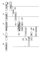
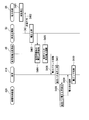
- FIG. 2 is a schematic block diagram showing a functional configuration of the first control device 42.
- the first control device 42 includes a voltage control unit 421, an interruption time command output unit 422, an event detection unit 423, a command switching unit 424, and a current control unit 425.
- the shutoff time command output unit 422 is referred to as an output unit 422.
- the voltage control unit 421 outputs a current command to the current control unit 425 at the normal time.
- the current command output by the voltage control unit 421 is generated so as to make the AC voltage and frequency offshore constant.
- the first converter 41 is controlled based on the voltage command controlled by the current control unit 425 based on the current command.
- the current control unit 425 generates a voltage command so that the current value of the first converter 41 becomes the current command value of the voltage control unit 421, and outputs the generated voltage command to the first converter 41.
- the output unit 422 outputs a command for cutting off or reducing the active power as a command at the time of abnormality. Note that when the effective power received by the first converter 41 is set to 0, it can also be realized by stopping the first converter 41.
- the abnormal time is, for example, a time when a failure should occur to stop power transmission by the DC power transmission unit 50.
- the command for cutting off the active power is, for example, a command for setting the active power received by the first converter 41 to zero.
- the event detection unit 423 detects the occurrence of a problem that should stop power transmission by the DC power transmission unit 50. For example, the event detection unit 423 detects the occurrence of a malfunction that should stop power transmission by the DC power transmission unit 50 by detecting that the voltage of the DC power transmission unit 50 has risen above a predetermined threshold.
- the method for the event detection unit 423 to detect a problem that should stop power transmission by the DC power transmission unit 50 is not limited to the method for detecting a voltage increase in the DC power transmission unit 50.
- the event detection unit 423 may receive a notification of occurrence of a failure through communication.
- the command switching unit 424 switches commands for the first converter 41. Specifically, in a state where the event detection unit 423 has not detected that the voltage of the DC power transmission unit 50 has risen above a predetermined threshold, the command switching unit 424 receives the current command from the voltage control unit 421. 1 to the converter 41. On the other hand, when the event detection unit 423 detects that the voltage of the DC power transmission unit 50 has risen above a predetermined threshold, the command switching unit 424 sends the current command from the output unit 422 to the first converter 41. Output to.
- the DC power transmission unit 50 transmits the power output from the first converter 41 to the second converter 71 using DC power.
- the braking resistor 62 is an electrical resistor for consuming surplus power when an accident occurs.
- the semiconductor switch 61 is normally open (off) and does not pass current. On the other hand, when surplus power is generated when an accident occurs, the semiconductor switch 61 is closed (ON), current is passed through the braking resistor 62, and the surplus power is consumed by the semiconductor switch 61.
- the second converter 71 converts the DC output from the DC power transmission unit 50 into AC power and outputs the AC power to the transformer 80.
- the second control device 72 controls power conversion by the second converter 71.
- the transformer 80 transforms the electric power from the second converter 71 to the voltage of the electric power system 90 and outputs it to the electric power system 90.
- the electric power system 90 is an electric power system of an electric power company, and transmits electric power from each power generation facility.
- the power generation control device 100 controls the torque of the hydraulic motor 14 (torque output from the hydraulic motor 14 to the synchronous generator 15).
- the power generation control device 100 reduces a torque command (a torque command to be output to the hydraulic motor 14) to the hydraulic motor 14 when an accident occurs.
- the power generation control device 100 controls power generation by the synchronous generator 15.
- the reduction here includes interruption (to zero). Therefore, the power generation control device 100 may issue a command to cut off the torque from the hydraulic motor 14 to the synchronous generator 15, or may issue a command to reduce this torque to a value larger than zero.
- blocking of the torque from the hydraulic motor 14 to the synchronous generator 15 is demonstrated to an example.
- the torque command for the hydraulic motor 14 is multiplied by the rotation speed of the synchronous generator 15, the torque command becomes equal to the active power command for the synchronous generator 15.
- the active power command and the torque command can be replaced.
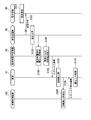
- FIG. 3 is a schematic block diagram illustrating a functional configuration of the power generation control device 100.
- the power generation control device 100 includes a blade pitch control unit 110, a pump control unit 120, a motor control unit 130, and a generator control unit 140.
- the motor control unit 130 includes a torque control unit 131, a cutoff command output unit 132, an event detection unit 133, and a command switching unit 134.
- the shut-off time command output unit 132 is referred to as an output unit 132.
- the blade pitch control unit 110 controls the pitch of the blades 11 (the angle of the blades 11).
- the pump control unit 120 controls the hydraulic pump 12.
- the motor control unit 130 controls the hydraulic motor 14.
- the torque control unit 131 generates a torque command for the hydraulic motor 14 at the normal time.
- the hydraulic motor 14 operates to output the torque of the command value (torque command) output from the torque control unit 131 to the synchronous generator 15.
- the output unit 132 outputs a torque command value 0 as a torque command to the hydraulic motor 14 at the time of abnormality.
- the hydraulic motor 14 blocks the torque output from the hydraulic motor 14 to the synchronous generator 15 based on the command value 0 output from the output unit 132.
- the event detection unit 133 balances the input torque to the synchronous generator 15 and the effective power output by the synchronous generator 15 that is generated by lowering the set value of the active power that the first converter 41 receives from the synchronous generator 15. Detect events caused by the collapse of Specifically, by reducing the set value of the active power that the first converter 41 receives from the synchronous generator 15, the input torque to the synchronous generator 15 is reduced with respect to the active power output by the synchronous generator 15. Become excessive. Thereby, the rotation speed of the synchronous generator 15 and the frequency of the electric power system to which the synchronous generator 15 is connected are increased, and the event detection unit 133 detects that the rotation speed is equal to or higher than a predetermined threshold value. Or you may make it the event detection part 133 detect that the frequency of the electric power grid
- the command switching unit 134 switches commands for the hydraulic motor 14. Specifically, in a state where the event detection unit 133 has not detected that the frequency of the power system to which the synchronous generator 15 is connected has exceeded a predetermined threshold value, the command switching unit 134 includes the torque control unit 131. Is output to the hydraulic motor 14. On the other hand, in a state where the event detection unit 133 detects that the frequency of the power system to which the synchronous generator 15 is connected has exceeded a predetermined threshold value, the command switching unit 134 outputs a command from the output unit 132. Output to the hydraulic motor 14.
- the command switching unit 134 corresponds to an example of a torque command lowering unit.
- the motor control unit 130 issues an input torque command to the hydraulic motor 14. Reduce. This is because by suppressing the mechanical torque from the hydraulic motor 14, an increase in the rotational speed of the synchronous generator 15 due to an excess of torque is avoided.
- the generator control unit 140 controls the synchronous generator 15.
- FIG. 4 is a diagram illustrating an example of processing performed by the dispatching power system 1 when an accident occurs.
- the first converter 41 controls the AC voltage and frequency between the wind turbine 10 and the first converter 41 to be constant.
- the event detection unit 133 constantly monitors the generator speed (or offshore system frequency), and the generator speed (or offshore system frequency) is a predetermined threshold (for example, 110 percent (%) of the rated speed). )) Is exceeded (step S108). Then, the command switching unit 134 blocks the input torque command to the hydraulic motor 14 (step S109). The surplus torque is accumulated in the rotor rotational speed of the wind turbine 10 (the rotational speed of the blades 11 and the rotating shaft). That is, the rotor speed increases.
- the blade pitch control is performed in the wind turbine 10 so as to keep the rotor rotational speed constant (step S110).
- the blade pitch control is performed in the wind turbine 10 so as to keep the rotor rotational speed constant (step S110).
- the 1st converter 41 which connects the synchronous generator 15 and the DC power transmission part 50 detects the malfunction which should stop the power transmission by the DC power transmission part 50 from the synchronous generator 15, 1st conversion
- the device 41 reduces the set value of the active power received from the synchronous generator 15.
- the event detection unit 133 detects an event caused by the balance breakdown between the torque input to the synchronous generator 15 and the active power output from the synchronous generator 15 caused thereby.
- the command switching unit 134 blocks the input torque command to the hydraulic motor 14.
- event detection part 133 detects the event resulting from a loss of balance, and 2nd converter 71, such as a connection point with electric power system 90, etc. It is possible to detect an accident on the electric power system 90 side.
- the event detection unit 133 has at least one of an increase in the number of revolutions of the synchronous generator 15 and an increase in the offshore system frequency (the frequency of the system to which the synchronous generator 15 is connected) as an event caused by the loss of balance. An event indicating that is detected.
- the event detection unit 133 is a simple process of monitoring the offshore system frequency such as the rotation speed of the synchronous generator 15 or the power generation frequency of the synchronous generator 15, and the power system 90 side from the second converter 71. Accidents can be detected.
- FIG. 5 is a diagram illustrating an example of processing performed by the dispatching power system 1 when an accident is removed.
- step S201 When the grid fault that occurred at the connection point with the power system 90 is removed (step S201) and power transmission is restored (step S202), the voltage of the DC power transmission unit 50 is restored to a steady state (step S203). While the system fault was continuing, the input torque to the synchronous generator 15 was excessive with respect to the active power output from the synchronous generator 15, and the rotational speed of the synchronous generator 15 was increasing.
- the first converter 41 detects that the voltage of the DC power transmission unit 50 has recovered to a steady state (step S204)
- the capacity of the first converter 41 and the output fluctuation of the synchronous generator 15 are allowed. Within the range, the frequency is quickly lowered (step S206). Specifically, by increasing the effective power received from the synchronous generator 15, the effective power output by the synchronous generator 15 is increased, thereby reducing the rotational speed and offshore system frequency of the synchronous generator 15.
- step S207 When the event detection unit 133 monitors the offshore frequency and detects that the offshore frequency is lower than the set value (system fault removal determination frequency) (step S207), the command switching unit 134 inputs to the hydraulic motor 14. Stopping the torque command is completed, and the torque control unit 131 resumes outputting the input torque command to the hydraulic motor 14 (step S208).
- the rotational speed of the rotor (the rotational speed of the blades 11 and the rotating shaft) and the rotational speed of the hydraulic pump 12 decrease as the torque output of the hydraulic motor 14 resumes, but the rotational speed of the rotor and the rotational speed of the hydraulic pump 12 remain constant as usual.
- the blade pitch control is performed as follows (step S209).
- the first converter 41 gradually lowers the frequency to the rating when the active power is stabilized (step S210).
- FIG. 6 is a graph showing an example of changes in offshore frequency, active power, and input torque command to the hydraulic motor 14 when the accident is removed.
- the horizontal axis in FIG. 6 indicates time.
- a line L11 indicates an offshore frequency
- a line L12 indicates an active power in the first converter 41
- a line L13 indicates an input torque command for the hydraulic motor 14.
- T ⁇ b> 11 when it is detected that a grid fault has occurred and the voltage of the DC power transmission unit 50 has risen above a predetermined threshold, the first converter 41 cuts off the output of active power to the DC power transmission unit 50. Or decrease (line L12). This increases the offshore frequency (line L11).
- the command switching unit 134 cuts off the torque from the hydraulic motor 14 to the synchronous generator 15 (line L11). Further, when the system fault is removed at time T13, the first converter 41 outputs active power to the DC power transmission unit 50 (line L12) and reduces the offshore frequency (line L13). At time T14, when the offshore frequency becomes equal to or lower than the threshold value (system fault removal determination frequency), the command switching unit 134 ends the cutoff of the torque from the hydraulic motor 14 to the synchronous generator 15, and the torque control unit 131 Is output to the wind turbine 10 (line L13). At time T15, the output restart from the wind turbine 10 is completed (line L13), and then the first converter 41 gradually reduces the offshore frequency to the rating (line L11).
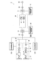
- FIG. 7 is a schematic block diagram showing a functional configuration of a dispatch power system in the fourth embodiment of the present invention.
- the same reference numerals (10 to 16, 20, 30, 41, 42, 50, 61, 62, 71, 72, 80, 90, 100) and description thereof is omitted.
- the first control device 42 and the power generation control device 100 communicate.
- FIG. 8 is a diagram illustrating an example of processing performed by the dispatching power system 2 when an accident is removed. Steps S301 to S304 in FIG. 8 are the same as steps S201 to S204 in FIG. After step S304, the first converter 41 operates so that the frequency of the offshore system at that time becomes constant (step S305). Further, the controller 300 transmits an output restart command via communication to the power generation control device 100 (step S306). Based on this command, the power generation control device 100 resumes outputting the input torque command to the hydraulic motor 14 that has been shut off (step S307). The rotor rotational speed decreases with the restart of the power output of the synchronous generator 15, but the blade pitch control is performed so that the rotor rotational speed is constant as usual (step S308). After the windmill 10 restarts the output, the first converter 41 reduces the offshore frequency to the rating according to the capacity of the first converter 41 (step S309).
- FIG. 9 is a graph illustrating an example of a change in frequency offshore frequency and a change in input torque command to the hydraulic motor 14 when communication is performed when an accident is removed.
- the horizontal axis in FIG. 9 indicates time.
- a line L21 indicates an offshore frequency
- a line L22 indicates an input torque command for the hydraulic motor 14.
- the command switching unit 134 blocks the input torque command to the hydraulic motor 14 (line L22). Further, when the system fault is removed at time T23, the first converter 41 operates to keep the offshore frequency constant (line L21). Further, the controller 300 transmits an output restart command to the power generation control device 100, and the power generation control device 100 restarts output of the input torque command to the synchronous generator 15 (line L22). At time T24, the output restart from the windmill 10 is completed (line L22), and then the first converter 41 gradually reduces the offshore frequency to the rating (line L21).
- the power converter When the power converter which connects a generator and the direct current power transmission part which transmits direct-current power detects the malfunction which should stop transmission by the direct current power transmission part from the generator, the power converter An event detector that detects an event caused by a loss of balance between the torque input to the generator and the active power output by the generator, which is generated by lowering the set value of the active power received from the generator. And a torque command lowering unit that reduces a torque command for a prime mover that outputs the torque input to the generator when the event detection unit detects an event caused by the loss of balance.
- an event detector that detects an event caused by a loss of balance between the torque input to the generator and the active power output by the generator, which is generated by lowering the set value of the active power received from the generator.
- a torque command lowering unit that reduces a torque command for a prime mover that outputs the torque input to the generator when the event detection unit detects an event caused by the loss of balance.
Landscapes
- Engineering & Computer Science (AREA)
- Power Engineering (AREA)
- Control Of Eletrric Generators (AREA)
Abstract
この発電制御装置は、発電機と直流電力を送電する直流送電部とを接続する電力変換器が、前記発電機からの前記直流送電部による送電を中止すべき不具合を検出した場合に、前記電力変換器が前記発電機から受け入れる有効電力の設定値を低下させて生じる、前記発電機へ入力されるトルクと前記発電機が出力する有効電力とのバランスの崩れに起因する事象を検出する事象検出部と、前記事象検出部が前記バランスの崩れに起因する事象を検出した場合、前記発電機へ入力される前記トルクを出力する原動機に対するトルク指令を低下させるトルク指令低下部と、を備える。
Description
本発明は、発電制御装置、電力変換器制御装置、発電制御方法およびプログラムに関する。
本願は、2015年2月3日に、日本に出願された特願2015-019695号に基づき優先権を主張し、その内容をここに援用する。
本願は、2015年2月3日に、日本に出願された特願2015-019695号に基づき優先権を主張し、その内容をここに援用する。
遠距離から大電力を送るための高圧直流送電(HVDC:High Voltage Direct Current)の採用が進んでいる。例えば洋上風車では、離岸距離が近い場合(数十キロメートル(km)以下)は交流送電が一般的だが、離岸距離が遠い場合、直流送電が用いられる。
洋上風車などの発電設備から電力系統への直流送電を行う場合において、電力系統との連系点に短絡又は地絡などの事故が発生し連係点の電圧が低下した場合、電力系統に電力を送電することができなくなる。一方、何も対策を行わない場合、風車などの発電設備側では事故を検知することができないため発電設備が発電を継続する。その結果、直流送電部の電力が過剰となり、直流送電部の電圧が上昇する。電圧上昇により、機器破壊などの障害が発生する可能性がある。
洋上風車などの発電設備から電力系統への直流送電を行う場合において、電力系統との連系点に短絡又は地絡などの事故が発生し連係点の電圧が低下した場合、電力系統に電力を送電することができなくなる。一方、何も対策を行わない場合、風車などの発電設備側では事故を検知することができないため発電設備が発電を継続する。その結果、直流送電部の電力が過剰となり、直流送電部の電圧が上昇する。電圧上昇により、機器破壊などの障害が発生する可能性がある。
かかる電圧上昇を防止するために、直流送電部に制動抵抗および半導体スイッチを設け、余剰電力を消散させる方法が考えられている。しかし、余剰電力の全てを消散させようとすると、制動抵抗、半導体スイッチともに容量が非常に大きくなり、コスト、重量、寸法の増加を招く。これは、直流送電を含む発電システム全体の発電コストを上昇させる一因となってしまう。
これに対し、特許文献1では、洋上風車を対象に、制動抵抗および半導体スイッチの容量を小さくする方法として、洋上の交流/直流変換器へ流入する洋上風車からの電力を制限するために、洋上変換器の交流側電圧を下げる方法が示されている。
特許文献1に記載の方法は、洋上風車が電力変換器を有しており、その出力電流の最大値が電力変換器で制限されることが前提となっている。
一方、一般的な発電設備では同期発電機による系統連系が主流である。また、風車でも同期発電機を用いて系統連系する方式が提案されている。ここで、同期発電機は電力変換器と比較して出力短絡時の電流(短絡電流)が大きい。そのため、風車側の交流/直流変換器が交流側電圧を下げようとしても、風車が電流を大きく流すことで電圧が下がらず、結果として風車が事故を検知できない可能性がある。
一方、一般的な発電設備では同期発電機による系統連系が主流である。また、風車でも同期発電機を用いて系統連系する方式が提案されている。ここで、同期発電機は電力変換器と比較して出力短絡時の電流(短絡電流)が大きい。そのため、風車側の交流/直流変換器が交流側電圧を下げようとしても、風車が電流を大きく流すことで電圧が下がらず、結果として風車が事故を検知できない可能性がある。
本発明は、風車などの発電設備における短絡電流が大きい場合でも、発電設備側で、電力系統との連系点など、直流送電部よりも電力系統側における事故(より具体的には、直流送電部と電力系統とを接続する電力変換器よりも電力系統側における事故)を検知することができる発電制御装置、電力変換器制御装置、発電制御方法およびプログラムを提供する。
本発明の第1の態様によれば、発電制御装置は、発電機と直流電力を送電する直流送電部とを接続する電力変換器が、前記発電機からの前記直流送電部による送電を中止すべき不具合を検出した場合に、前記電力変換器が前記発電機から受け入れる有効電力の設定値を低下させて生じる、前記発電機へ入力されるトルクと前記発電機が出力する有効電力とのバランスの崩れに起因する事象を検出する事象検出部と、前記事象検出部が前記バランスの崩れに起因する事象を検出した場合、前記発電機へ入力される前記トルクを出力する原動機に対するトルク指令を低下させるトルク指令低下部と、を備える。
前記事象検出部は、前記バランスの崩れに起因する事象として、前記発電機の回転数の増加または前記発電機が接続された電力系統の周波数の増加の少なくともいずれかを示す事象を検出するようにしてもよい。
前記事象検出部は、前記バランスの崩れに起因する事象として、前記発電機からの有効電力と前記原動機に対するトルク指令との偏差の増加を検出するようにしてもよい。
前記発電機と前記電力変換器との間に、前記発電機からの電力を直流電力にて通電させる直流バスが設けられており、前記事象検出部は、前記バランスの崩れに起因する事象として、前記直流バスにおける電圧の上昇を検出するようにしてもよい。
本発明の第2の態様によれば、電力変換器制御装置は、発電機と直流電力を送電する直流送電部とを接続する電力変換器を制御する電力変換器制御装置であって、前記発電機からの前記直流送電部による送電を中止すべき不具合を検出した場合に、前記電力変換器が前記発電機から受け入れる有効電力の設定値を低下させる。
本発明の第3の態様によれば、発電制御方法は、発電機と直流電力を送電する直流送電部とを接続する電力変換器が、前記発電機からの前記直流送電部による送電を中止すべき不具合を検出した場合に、前記電力変換器が前記発電機から受け入れる有効電力の設定値を低下させて生じる、前記発電機へ入力されるトルクと前記発電機が出力する有効電力とのバランスの崩れに起因する事象を検出するステップと、前記バランスの崩れに起因する事象を検出した場合、前記発電機へ入力される前記トルクを出力する原動機に対するトルク指令を低下させるステップと、を有する。
本発明の第4の態様によれば、プログラムは、コンピュータに、発電機と直流電力を送電する直流送電部とを接続する電力変換器が、前記発電機からの前記直流送電部による送電を中止すべき不具合を検出した場合に、前記電力変換器が前記発電機から受け入れる有効電力の設定値を低下させて生じる、前記発電機へ入力されるトルクと前記発電機が出力する有効電力とのバランスの崩れに起因する事象を検出するステップと、前記バランスの崩れに起因する事象を検出した場合、前記発電機へ入力される前記トルクを出力する原動機に対するトルク指令を低下させるステップと、を実行させるためのプログラムである。
上記した発電制御装置、電力変換器、発電制御方法およびプログラムによれば、発電設備における短絡電流が大きい場合でも、発電設備側で、直流送電部と電力系統とを接続する電力変換器よりも電力系統側における事故を検知することができる。
以下、本発明の実施形態を説明するが、以下の実施形態は請求の範囲にかかる発明を限定しない。また、実施形態の中で説明されている特徴の組み合わせの全てが発明の解決手段に必須であるとは限らない。
<第1の実施形態>
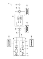
図1は、本発明の第1の実施形態における発送電システムの機能構成を示す概略ブロック図である。図1において、発送電システム1は、風車10と、交流母線20と、変圧器30と、風車側電力変換器41と、風車側変換器制御装置42と、直流送電部50と、半導体スイッチ61と、制動抵抗62と、系統側電力変換器71と、系統側変換器制御装置72と変圧器80と、発電制御装置100とを備える。風車10は、翼11と、油圧ポンプ12と、アキュムレータ13と、油圧モータ14と、同期発電機15と、変圧器16とを備える。以下、風車側電力変換器41を第1変換器41と称する。風車側変換器制御装置42を第1制御装置42と称する。系統側電力変換器71を第2変換器71と称する。系統側変換器制御装置72を第2制御装置72と称する。
発送電システム1は、変圧器80にて電力系統90と接続されている。
後述するように、発送電システム1が半導体スイッチ61と制動抵抗62とを備えない構成となる場合もある。
発送電システム1が備える風車の数は2つに限らず1つ以上であればよい。
また、第1の実施形態における発電設備は風車に限らない。例えば、発送電システム1が、火力発電設備または水力発電設備など風車以外の発電設備を備えていてもよい。また、発送電システム1が、風車と火力発電設備とを備えるなど、複数種類の発電設備を備えていてもよい。
また、第1の実施形態における発電設備は風車に限らない。例えば、発送電システム1が、火力発電設備または水力発電設備など風車以外の発電設備を備えていてもよい。また、発送電システム1が、風車と火力発電設備とを備えるなど、複数種類の発電設備を備えていてもよい。
風車10は、風力を受けて発電し、発電した電力を、直流送電部50を介して電力系統90へ供給する。風車10は、例えば海洋に設置される洋上風車である。但し、風車10の設置場所は洋上に限らず陸上であってもよい。
風車10において、翼11が受ける風力エネルギーによって油圧ポンプ12が駆動され、油圧ポンプ12によって油圧モータ14が駆動され、油圧モータ14からの機械的エネルギーによって同期発電機15が駆動される。すなわち、翼11が風力を受けて回転すると、翼11からの回転エネルギーによって油圧ポンプ12が駆動され、油圧を生じさせる。油圧ポンプ12からの油圧により油圧モータ14が駆動されて同期発電機15のロータを回転させる。この回転エネルギーにより同期発電機15が交流電力を発電する。なお、アキュムレータ13には油圧伝達用の油が蓄えられている。このように、第1の実施形態では、風車10が油圧駆動により同期発電機15を動作させる場合を例に説明している。
風車10において、翼11が受ける風力エネルギーによって油圧ポンプ12が駆動され、油圧ポンプ12によって油圧モータ14が駆動され、油圧モータ14からの機械的エネルギーによって同期発電機15が駆動される。すなわち、翼11が風力を受けて回転すると、翼11からの回転エネルギーによって油圧ポンプ12が駆動され、油圧を生じさせる。油圧ポンプ12からの油圧により油圧モータ14が駆動されて同期発電機15のロータを回転させる。この回転エネルギーにより同期発電機15が交流電力を発電する。なお、アキュムレータ13には油圧伝達用の油が蓄えられている。このように、第1の実施形態では、風車10が油圧駆動により同期発電機15を動作させる場合を例に説明している。
翼11と、油圧ポンプ12と、アキュムレータ13と、油圧モータ14との組み合わせは原動機の例に該当し、同期発電機15へ入力されるトルク(機械トルク)を出力することで、同期発電機15のロータを回転駆動させる。
ここでいう原動機は、自然界に存在するエネルギーを機械的エネルギーに変換する機器である。ここでいう自然界に存在するエネルギーは、様々なエネルギーであってよい。例えば、自然界に存在するエネルギーは、石炭または石油などの燃料による熱エネルギーであってもよいし、地熱または太陽熱などの熱エネルギーであってもよいし、太陽光などの光エネルギーであってもよいし、風力または水力などの運動エネルギーまたは位置エネルギーであってもよい。第1の実施形態では、自然界に存在するエネルギーが風力である場合を例に説明する。
同期発電機15が発電した電力に対し、変圧器16が交流母線20の電圧への変圧を行って交流母線20へ出力する。
交流母線20は、風車10の各々から出力される電力を変圧器30へ伝送する。
変圧器30は、交流母線20からの電力に対して電圧変換を行って第1変換器41へ出力する。
第1変換器41は、発電機と直流電力を送電する直流送電部とを接続し、変圧器30からの電力(交流電力)を直流電力に変換して直流送電部50へ出力する。
第1変換器41は、発電機と直流電力を送電する直流送電部とを接続し、変圧器30からの電力(交流電力)を直流電力に変換して直流送電部50へ出力する。
第1制御装置42は、第1変換器41による電力変換を制御する。特に、第1制御装置42が、例えば電力系統90との連系点における事故など、直流送電部50による送電を中止すべき不具合を検出した場合について説明する。この場合、第1制御装置42は、第1変換器41が同期発電機15から受け入れる有効電力の設定値(有効電力指令)を低下させる。第1制御装置42は、電力変換器制御装置の例に該当する。
例えば、第1制御装置42は、直流送電部50から電力系統90へ電力を出力できないことにより、直流送電部50の電圧が所定の閾値以上に上昇したことを検出する。すると、第1変換器41が同期発電機15から受け入れる有効電力の設定値を低下させる。なお、ここでの低下には遮断も含まれる。有効電力の設定値の遮断とは、有効電力の設定値を0にすることである。従って、第1制御装置42が、第1変換器41に、同期発電機15から受け入れる有効電力を遮断させるようにしてもよいし、この有効電力を0よりも大きい値に低減させるようにしてもよい。以下では、第1制御装置42が、第1変換器41に、同期発電機15から受け入れる有効電力を遮断させる場合を例に説明する。
図2は、第1制御装置42の機能構成を示す概略ブロック図である。図2において、第1制御装置42は、電圧制御部421と、遮断時指令出力部422と、事象検出部423と、指令切替部424と、電流制御部425とを備える。以下、遮断時指令出力部422を出力部422と称する。
電圧制御部421は、通常時における電流制御部425への電流指令を出力する。電圧制御部421が出力する電流指令は、洋上の交流電圧及び周波数を一定にするように生成される。通常時において、第1変換器41は、この電流指令に基づいて電流制御部425で制御された電圧指令に基づいて制御される。すなわち、電流制御部425は、第1変換器41の電流値が電圧制御部421の電流指令値になるように電圧指令を生成し、生成した電圧指令を第1変換器41に出力する。
出力部422は、異常時における指令として、有効電力を遮断する指令または低下させる指令を出力する。なお、第1変換器41が受け入れる有効電力を0にする場合は、第1変換器41を停止することでも実現可能である。異常時とは、例えば、直流送電部50による送電を中止すべき不具合発生時である。有効電力を遮断する指令とは、例えば、第1変換器41が受け入れる有効電力を0にする指令である。
事象検出部423は、直流送電部50による送電を中止すべき不具合の発生を検出する。例えば、事象検出部423は、直流送電部50の電圧が所定の閾値以上に上昇したことを検出することにより、直流送電部50による送電を中止すべき不具合の発生を検出する。
但し、事象検出部423が、直流送電部50による送電を中止すべき不具合を検出する方法は、直流送電部50の電圧上昇を検出する方法に限らない。例えば、事象検出部423が通信により不具合発生の通知を受けるようにしてもよい。
但し、事象検出部423が、直流送電部50による送電を中止すべき不具合を検出する方法は、直流送電部50の電圧上昇を検出する方法に限らない。例えば、事象検出部423が通信により不具合発生の通知を受けるようにしてもよい。
指令切替部424は、第1変換器41に対する指令の切替を行う。具体的には、事象検出部423が、直流送電部50の電圧が所定の閾値以上に上昇したことを検出していない状態では、指令切替部424は、電圧制御部421からの電流指令を第1変換器41へ出力する。一方、事象検出部423が、直流送電部50の電圧が所定の閾値以上に上昇したことを検出している状態では、指令切替部424は、出力部422からの電流指令を第1変換器41へ出力する。
直流送電部50は、第1変換器41から出力される電力を直流電力にて第2変換器71へ送電する。
制動抵抗62は、事故発生時に余剰電力を消費させるための電気抵抗である。
半導体スイッチ61は、通常時は開状態(オフ)になっており、電流を流さない。一方、事故発生時に余剰電力が生じると、半導体スイッチ61は、閉状態(オン)になって制動抵抗62に電流を流し、余剰電力を半導体スイッチ61に消費させる。
制動抵抗62は、事故発生時に余剰電力を消費させるための電気抵抗である。
半導体スイッチ61は、通常時は開状態(オフ)になっており、電流を流さない。一方、事故発生時に余剰電力が生じると、半導体スイッチ61は、閉状態(オン)になって制動抵抗62に電流を流し、余剰電力を半導体スイッチ61に消費させる。
第2変換器71は、直流送電部50からの直流出力を交流電力に変換して変圧器80へ出力する。
第2制御装置72は、第2変換器71による電力変換を制御する。
変圧器80は、第2変換器71からの電力に対し電力系統90の電圧への変圧を行って電力系統90へ出力する。
電力系統90は、電力会社の電力系統であり、各発電設備からの電力を送電する。
第2制御装置72は、第2変換器71による電力変換を制御する。
変圧器80は、第2変換器71からの電力に対し電力系統90の電圧への変圧を行って電力系統90へ出力する。
電力系統90は、電力会社の電力系統であり、各発電設備からの電力を送電する。
発電制御装置100は、油圧モータ14のトルク(油圧モータ14が同期発電機15へ出力するトルク)を制御する。特に、発電制御装置100は、事故発生時に、油圧モータ14に対するトルク指令(油圧モータ14に出力させるトルクの指令)を低下させる。これにより、発電制御装置100は、同期発電機15による発電を制御する。
なお、ここでの低下には遮断(0にすること)も含まれる。従って、発電制御装置100が、油圧モータ14から同期発電機15へのトルクの遮断を指令するようにしてもよいし、このトルクを0よりも大きい値に低減させる指令を行うようにしてもよい。以下では、発電制御装置100が、油圧モータ14から同期発電機15へのトルクの遮断を指令する場合を例に説明する。
ここで、油圧モータ14に対するトルク指令に同期発電機15の回転数を乗算すると、同期発電機15に対する有効電力指令に等しくなる。このように、有効電力指令とトルク指令とを読み替えることができる。
なお、ここでの低下には遮断(0にすること)も含まれる。従って、発電制御装置100が、油圧モータ14から同期発電機15へのトルクの遮断を指令するようにしてもよいし、このトルクを0よりも大きい値に低減させる指令を行うようにしてもよい。以下では、発電制御装置100が、油圧モータ14から同期発電機15へのトルクの遮断を指令する場合を例に説明する。
ここで、油圧モータ14に対するトルク指令に同期発電機15の回転数を乗算すると、同期発電機15に対する有効電力指令に等しくなる。このように、有効電力指令とトルク指令とを読み替えることができる。
図3は、発電制御装置100の機能構成を示す概略ブロック図である。図3において、発電制御装置100は、翼ピッチ制御部110と、ポンプ制御部120と、モータ制御部130と、発電機制御部140とを備える。モータ制御部130は、トルク制御部131と、遮断時指令出力部132と、事象検出部133と、指令切替部134とを備える。以下、遮断時指令出力部132を出力部132と称する。
翼ピッチ制御部110は、翼11のピッチ(翼11の角度)を制御する。
ポンプ制御部120は、油圧ポンプ12を制御する。
翼ピッチ制御部110は、翼11のピッチ(翼11の角度)を制御する。
ポンプ制御部120は、油圧ポンプ12を制御する。
モータ制御部130は、油圧モータ14を制御する。
トルク制御部131は、通常時における油圧モータ14に対するトルク指令を生成する。通常時において、油圧モータ14は、トルク制御部131が出力する指令値(トルク指令)のトルクを同期発電機15へ出力するよう動作する。
出力部132は、異常時における油圧モータ14へのトルク指令として、トルクの指令値0を出力する。異常時において、油圧モータ14は、出力部132が出力する指令値0に基づいて、油圧モータ14から同期発電機15へのトルクの出力を遮断する。
トルク制御部131は、通常時における油圧モータ14に対するトルク指令を生成する。通常時において、油圧モータ14は、トルク制御部131が出力する指令値(トルク指令)のトルクを同期発電機15へ出力するよう動作する。
出力部132は、異常時における油圧モータ14へのトルク指令として、トルクの指令値0を出力する。異常時において、油圧モータ14は、出力部132が出力する指令値0に基づいて、油圧モータ14から同期発電機15へのトルクの出力を遮断する。
事象検出部133は、第1変換器41が同期発電機15から受け入れる有効電力の設定値を低下させて生じる、同期発電機15への入力トルクと同期発電機15が出力する有効電力とのバランスの崩れに起因する事象を検出する。具体的には、第1変換器41が同期発電機15から受け入れる有効電力の設定値を低下させることで、同期発電機15への入力トルクが、同期発電機15が出力する有効電力に対して過剰になる。これにより同期発電機15の回転数、および、同期発電機15が接続された電力系統の周波数が上昇し、事象検出部133は、この回転数が所定の閾値以上になったことを検出する。
あるいは、事象検出部133が、同期発電機15が接続された電力系統の周波数が所定の閾値以上になったことを検出するようにしてもよい。
あるいは、事象検出部133が、同期発電機15が接続された電力系統の周波数が所定の閾値以上になったことを検出するようにしてもよい。
指令切替部134は、油圧モータ14に対する指令の切替を行う。具体的には、事象検出部133が、同期発電機15が接続された電力系統の周波数が所定の閾値以上になったことを検出していない状態では、指令切替部134は、トルク制御部131からの指令を油圧モータ14へ出力する。一方、事象検出部133が、同期発電機15が接続された電力系統の周波数が所定の閾値以上になったことを検出している状態では、指令切替部134は、出力部132からの指令を油圧モータ14へ出力する。指令切替部134は、トルク指令低下部の例に該当する。
このように、モータ制御部130は、事象検出部133が、同期発電機15が接続された電力系統の周波数が所定の閾値以上になったことを検出すると、油圧モータ14への入力トルク指令を低下させる。油圧モータ14からの機械トルクを抑制することで、トルクの余剰による同期発電機15の回転数上昇を回避するためである。
発電機制御部140は、同期発電機15を制御する。
発電機制御部140は、同期発電機15を制御する。
次に、図4を参照して発送電システム1の動作について説明する。
図4は、事故発生時に発送電システム1が行う処理の例を示す図である。
通常時においては、第1変換器41は、風車10と第1変換器41との間の交流電圧および周波数が一定になるよう制御している。
図4は、事故発生時に発送電システム1が行う処理の例を示す図である。
通常時においては、第1変換器41は、風車10と第1変換器41との間の交流電圧および周波数が一定になるよう制御している。
一方、例えば電力系統との連系点で系統事故が発生するなど(ステップS101)、電力系統への送電ができなくなると(ステップS102)、直流送電部50の電力が過剰となり直流送電部50の電圧が上昇する(ステップS103)。
第1変換器41は、直流送電部50の電圧が所定の閾値以上に上昇したことを検知すると(ステップS104)、第1変換器41が風車10から受け入れる有効電力の設定値を低下させる(ステップS105)。これにより、同期発電機15への入力トルクが、同期発電機15が出力する有効電力に対して過剰になることで(ステップS106)、同期発電機15の回転数が上昇する(ステップS107)。同期発電機15の回転数の上昇に伴い、発電の周波数(洋上系統周波数)も上昇する。ここでいう洋上系統は、風車10から第1変換器41までの電力系統である。
第1変換器41は、直流送電部50の電圧が所定の閾値以上に上昇したことを検知すると(ステップS104)、第1変換器41が風車10から受け入れる有効電力の設定値を低下させる(ステップS105)。これにより、同期発電機15への入力トルクが、同期発電機15が出力する有効電力に対して過剰になることで(ステップS106)、同期発電機15の回転数が上昇する(ステップS107)。同期発電機15の回転数の上昇に伴い、発電の周波数(洋上系統周波数)も上昇する。ここでいう洋上系統は、風車10から第1変換器41までの電力系統である。
発電制御装置100において事象検出部133が、発電機回転数(または洋上系統周波数)を常時監視し、発電機回転数(または洋上系統周波数)が所定の閾値(例えば定格回転数の110パーセント(%))を超えたことを検出する(ステップS108)。すると、指令切替部134が、油圧モータ14への入力トルク指令を遮断する(ステップS109)。
余剰となったトルクは風車10のロータ回転数(翼11および回転軸の回転数)に蓄積される。すなわちロータ回転数が上昇する。
余剰となったトルクは風車10のロータ回転数(翼11および回転軸の回転数)に蓄積される。すなわちロータ回転数が上昇する。
ここで、一般の風車と同様、風車10では、ロータ回転数を一定にするように翼ピッチ制御が実施されている(ステップS110)。この翼ピッチ制御で入力エネルギーを低減させることにより、風車10の過回転による停止(トリップ)を防止することが可能である。
以上のように、同期発電機15と直流送電部50とを接続する第1変換器41が、同期発電機15からの直流送電部50による送電を中止すべき不具合を検出した場合、第1変換器41は、同期発電機15から受け入れる有効電力の設定値を低下させる。そして、事象検出部133は、これによって生じる、同期発電機15へ入力されるトルクと同期発電機15が出力する有効電力とのバランスの崩れに起因する事象を検出する。
そして、事象検出部133がバランスの崩れに起因する事象を検出した場合、指令切替部134は、油圧モータ14への入力トルク指令を遮断する。
このように、事象検出部133が、バランスの崩れに起因する事象を検出することで、同期発電機15の短絡電流が大きい場合でも、電力系統90との連系点など、第2変換器71よりも電力系統90側における事故を検知することができる。
そして、事象検出部133がバランスの崩れに起因する事象を検出した場合、指令切替部134は、油圧モータ14への入力トルク指令を遮断する。
このように、事象検出部133が、バランスの崩れに起因する事象を検出することで、同期発電機15の短絡電流が大きい場合でも、電力系統90との連系点など、第2変換器71よりも電力系統90側における事故を検知することができる。
また、事象検出部133は、バランスの崩れに起因する事象として、同期発電機15の回転数の増加または洋上系統周波数(同期発電機15が接続されている系統の周波数)の増加の少なくともいずれかを示す事象を検出する。
これにより、事象検出部133は、同期発電機15の回転数、または、同期発電機15の発電周波数など洋上系統周波数を監視するという簡単な処理で、第2変換器71よりも電力系統90側における事故を検知することができる。
これにより、事象検出部133は、同期発電機15の回転数、または、同期発電機15の発電周波数など洋上系統周波数を監視するという簡単な処理で、第2変換器71よりも電力系統90側における事故を検知することができる。
また、直流送電部50の電圧上昇に基づき、第1変換器41が直流送電部50へ流れ込む有効電力を低下させるので、直流送電部50に設置される半導体スイッチ61、制動抵抗62ともに、容量低減が可能、もしくは設置不要となる。半導体スイッチ61および制動抵抗62の設置要否は、風車10における回転数(同期発電機15や回転軸等の回転数)の上昇がどこまで許容されるかに依存する。
また、異常伝達に周波数を使用するため、風車10と第1変換器41とが離れて設置されていても、風車10と第1変換器41と間の電力ケーブルが正常に接続され、かつ、事象検出部133が備える周波数検出器が正常であれば異常を検出することが可能である。通信で異常を伝達する方式も考えられるが、通信ケーブル断線、ノイズによる通信エラー等により異常伝達ができなくなるリスクが考えられる。この点において、事象検出部133がバランスの崩れに起因する事象を検出する方が通信で異常を伝達するよりも信頼性が高い。
<第2の実施形態>
事象検出部が異常を検出する方法は、周波数による方法に限らない。第2の実施形態では、事象検出部が有効電力の指令値と測定値との偏差に基づいて異常を検出する場合について説明する。
第2の実施形態における装置の構成は図1~図3と同様であり、図示および説明を省略する。第2の実施形態では、事象検出部133(図3)が異常を検出する処理が、第1の実施形態の場合と異なる。
事象検出部133は、同期発電機15に対する有効電力指令と、有効電力の測定値との偏差に基づいて異常(直流送電部50による送電を中止すべき不具合)を検出する。
ここで、発電機の周波数と有効電力との関係は、式(1)のように示される。
事象検出部が異常を検出する方法は、周波数による方法に限らない。第2の実施形態では、事象検出部が有効電力の指令値と測定値との偏差に基づいて異常を検出する場合について説明する。
第2の実施形態における装置の構成は図1~図3と同様であり、図示および説明を省略する。第2の実施形態では、事象検出部133(図3)が異常を検出する処理が、第1の実施形態の場合と異なる。
事象検出部133は、同期発電機15に対する有効電力指令と、有効電力の測定値との偏差に基づいて異常(直流送電部50による送電を中止すべき不具合)を検出する。
ここで、発電機の周波数と有効電力との関係は、式(1)のように示される。

但し、「M」は慣性定数を表し、「PW」は発電機への機械入力(単位はワット[W])を表し、「PG」は発電機有効電力(単位はワット)を表す。
また、「ω」は発電機の回転角速度(単位はラジアン毎秒(rad/s))を表し、式(2)のように示される。
また、「ω」は発電機の回転角速度(単位はラジアン毎秒(rad/s))を表し、式(2)のように示される。

但し、「f」は発電機の回転数(単位はヘルツ(Hz))を表す。
また、慣性定数「M」は式(3)のように示される。
また、慣性定数「M」は式(3)のように示される。

但し、「J」は慣性モーメント(単位はキログラム平方メートル(kg・m2)を表し、「ωs」は発電機同期速度(単位はラジアン毎秒)を表す。
式(1)を参照すると、発電機の回転角速度ωの微分と、発電機への機械入力から発電機の有効電力を減算した差とが比例している。このことから、事故発生時に発電機の回転角速度が徐々に上昇するのに対し、発電機への機械入力から発電機の有効電力を減算した差は、すぐに変化する。
式(1)を参照すると、発電機の回転角速度ωの微分と、発電機への機械入力から発電機の有効電力を減算した差とが比例している。このことから、事故発生時に発電機の回転角速度が徐々に上昇するのに対し、発電機への機械入力から発電機の有効電力を減算した差は、すぐに変化する。
また、風車では通常、風速やロータ回転数に基づいて風車が出力すべき有効電力指令PW0
(ref)(またはトルク指令)は常時計算されている。また、発電機の有効電力PGは測定されている。
事象検出部133は、有効電力に基づいて、異常(直流送電部50による送電を中止すべき不具合)を検出する。具体的には、有効電力偏差(風車10が出力すべき有効電力の指令値と実際の有効電力との差)の閾値εpを予め設定し、式(4)に基づいて異常の有無を判定する。
事象検出部133は、有効電力に基づいて、異常(直流送電部50による送電を中止すべき不具合)を検出する。具体的には、有効電力偏差(風車10が出力すべき有効電力の指令値と実際の有効電力との差)の閾値εpを予め設定し、式(4)に基づいて異常の有無を判定する。

すなわち、事象検出部133が、有効電力指令PW0
(ref)と発電機有効電力計測値PGとの偏差がεpよりも大きくなったことを検出した場合に、指令切替部134が指令を切り替えて、有効電力を遮断する。なお、判定の誤動作防止のためにフィルタ処理を付加してもよい。
以上のように、事象検出部133は、バランスの崩れに起因する事象として、同期発電機15からの有効電力と同期発電機15に対する有効電力指令との偏差の増加を検出する。
これにより、事象検出部133は、周波数に基づく場合よりも速やかに異常を検知し得る。
なお、第2の実施形態と第1の実施形態とは両立し得る。例えば、事象検出部が、周波数に基づく異常検出、有効電力に基づく異常検出の両方を行うようにしてもよい。
これにより、事象検出部133は、周波数に基づく場合よりも速やかに異常を検知し得る。
なお、第2の実施形態と第1の実施形態とは両立し得る。例えば、事象検出部が、周波数に基づく異常検出、有効電力に基づく異常検出の両方を行うようにしてもよい。
<第3の実施形態>
第3の実施形態では、第1の実施形態の構成(図1)における、事故が除去された際の処理について説明する。なお、第2の実施形態の構成における、事故が除去された際の処理も同様とすることができる。
第3の実施形態における装置の構成は図1と同様であり、図示および説明を省略する。
第3の実施形態では、第1の実施形態の構成(図1)における、事故が除去された際の処理について説明する。なお、第2の実施形態の構成における、事故が除去された際の処理も同様とすることができる。
第3の実施形態における装置の構成は図1と同様であり、図示および説明を省略する。
図5は、事故が除去された際に発送電システム1が行う処理の例を示す図である。
電力系統90との連系点で発生した系統事故が除去され(ステップS201)、送電が回復した場合(ステップS202)、直流送電部50の電圧が定常状態に回復する(ステップS203)。
系統事故が継続している間は同期発電機15への入力トルクが、同期発電機15が出力する有効電力に対して過剰になることで、同期発電機15の回転数が上昇していた。これに対し、第1変換器41は、直流送電部50の電圧が定常状態に回復したことを検知すると(ステップS204)直ちに、第1変換器41の容量および同期発電機15の出力変動の許容範囲内で、迅速に周波数を下げるよう動作する(ステップS206)。具体的には、同期発電機15から受け入れる有効電力を増加させることで、同期発電機15が出力する有効電力を増加させ、これにより同期発電機15の回転数および洋上系統周波数を低下させる。
事象検出部133が、洋上周波数を監視しておき、洋上周波数が設定値(系統事故除去判定周波数)を下回ったことを検出すると(ステップS207)、指令切替部134が、油圧モータ14への入力トルク指令の遮断を終了し、トルク制御部131が、油圧モータ14への入力トルク指令の出力を再開する(ステップS208)。
油圧モータ14のトルク出力再開に伴ってロータ回転数(翼11および回転軸の回転数)および油圧ポンプ12の回転数が下がってくるが、通常通りロータ回転数および油圧ポンプ12の回転数を一定とするように翼ピッチ制御が実施される(ステップS209)。
第1変換器41は、有効電力が安定した時点で、徐々に周波数を定格まで下げる(ステップS210)。
油圧モータ14のトルク出力再開に伴ってロータ回転数(翼11および回転軸の回転数)および油圧ポンプ12の回転数が下がってくるが、通常通りロータ回転数および油圧ポンプ12の回転数を一定とするように翼ピッチ制御が実施される(ステップS209)。
第1変換器41は、有効電力が安定した時点で、徐々に周波数を定格まで下げる(ステップS210)。
図6は、事故が除去された際の、洋上周波数、有効電力および油圧モータ14への入力トルク指令の変化の例を示すグラフである。
図6の横軸は時刻を示す。また、線L11は洋上周波数を示し、線L12は第1変換器41における有効電力を示し、線L13は油圧モータ14に対する入力トルク指令を示す。
時刻T11において、系統事故が発生して直流送電部50の電圧が所定の閾値以上に上昇したことを検知すると、第1変換器41は、直流送電部50への有効電力の出力を遮断する、または低下させる(線L12)。これにより、洋上周波数が上昇する(線L11)。
図6の横軸は時刻を示す。また、線L11は洋上周波数を示し、線L12は第1変換器41における有効電力を示し、線L13は油圧モータ14に対する入力トルク指令を示す。
時刻T11において、系統事故が発生して直流送電部50の電圧が所定の閾値以上に上昇したことを検知すると、第1変換器41は、直流送電部50への有効電力の出力を遮断する、または低下させる(線L12)。これにより、洋上周波数が上昇する(線L11)。
時刻T12において、洋上周波数が閾値(系統事故判定周波数)よりも上昇すると、指令切替部134が、油圧モータ14から同期発電機15へのトルクを遮断させる(線L11)。
また、時刻T13において、系統事故が除去されると、第1変換器41が有効電力を直流送電部50へ出力して(線L12)、洋上周波数を低減させる(線L13)。
時刻T14において、洋上周波数が閾値(系統事故除去判定周波数)以下になると、指令切替部134が油圧モータ14から同期発電機15へのトルクの遮断を終了し、トルク制御部131が、油圧モータ14へのトルク指令を風車10へ出力する(線L13)。
時刻T15において、風車10からの出力再開を完了し(線L13)、その後、第1変換器41が、洋上周波数を定格まで徐々に下げていく(線L11)。
また、時刻T13において、系統事故が除去されると、第1変換器41が有効電力を直流送電部50へ出力して(線L12)、洋上周波数を低減させる(線L13)。
時刻T14において、洋上周波数が閾値(系統事故除去判定周波数)以下になると、指令切替部134が油圧モータ14から同期発電機15へのトルクの遮断を終了し、トルク制御部131が、油圧モータ14へのトルク指令を風車10へ出力する(線L13)。
時刻T15において、風車10からの出力再開を完了し(線L13)、その後、第1変換器41が、洋上周波数を定格まで徐々に下げていく(線L11)。
以上の処理により、発送電システム1は、連系点で発生した系統事故が除去され、出力再開が可能となった際に、系統周波数を安定に保ちながら出力を再開することが可能となる。
<第4の実施形態>
事故が除去されたことの通知は、上記のように洋上周波数による通知に限らない。第4の実施形態では、事故が除去されたことを通信にて通知する例について説明する。第4の実施形態も、第1の実施形態、第2の実施形態の何れにも適用し得る。
図7は、本発明の第4の実施形態における発送電システムの機能構成を示す概略ブロック図である。
図7において、図1の各部に対応して同様の機能を有する部分には同一の符号(10~16、20、30、41、42、50、61、62、71、72、80、90、100)を付し、説明を省略する。
事故が除去されたことの通知は、上記のように洋上周波数による通知に限らない。第4の実施形態では、事故が除去されたことを通信にて通知する例について説明する。第4の実施形態も、第1の実施形態、第2の実施形態の何れにも適用し得る。
図7は、本発明の第4の実施形態における発送電システムの機能構成を示す概略ブロック図である。
図7において、図1の各部に対応して同様の機能を有する部分には同一の符号(10~16、20、30、41、42、50、61、62、71、72、80、90、100)を付し、説明を省略する。
図7に示される発送電システム2では、図1の構成に加えて、第1制御装置42と発電制御装置100とが通信を行う。
図8は、事故が除去された際に発送電システム2が行う処理の例を示す図である。
図8のステップS301~304は、図5のステップS201~204と同様である。
ステップS304の後、第1変換器41は、その時点での洋上系統の周波数が一定となるように動作する(ステップS305)。また、制御器300が、発電制御装置100に対し通信経由で出力再開指令を送信する(ステップS306)。発電制御装置100は、この指令に基づいて、遮断していた油圧モータ14への入力トルク指令の出力を再開する(ステップS307)。
同期発電機15の電力出力再開に伴ってロータ回転数が下がってくるが、通常通りロータ回転数を一定とするように翼ピッチ制御が実施される(ステップS308)。
風車10が出力を再開した後、第1変換器41は、第1変換器41の容量の余力に応じて洋上の周波数を定格まで低下させる(ステップS309)。
図9は、事故が除去された際に通信による場合の、周波数洋上周波数の変化、および、油圧モータ14への入力トルク指令の変化の例を示すグラフである。
図9の横軸は時刻を示す。また、線L21は洋上周波数を示し、線L22は油圧モータ14に対する入力トルク指令を示す。
時刻T21において、系統事故が発生すると、第1変換器41が直流送電部50への有効電力の出力を遮断し、洋上周波数が上昇する(線L21)。
図9の横軸は時刻を示す。また、線L21は洋上周波数を示し、線L22は油圧モータ14に対する入力トルク指令を示す。
時刻T21において、系統事故が発生すると、第1変換器41が直流送電部50への有効電力の出力を遮断し、洋上周波数が上昇する(線L21)。
時刻T22において、洋上周波数が閾値(系統事故判定周波数)よりも上昇すると、指令切替部134が、油圧モータ14への入力トルク指令を遮断する(線L22)。
また、時刻T23において、系統事故が除去されると、第1変換器41は、洋上周波数を一定に保つよう動作する(線L21)。また、制御器300が発電制御装置100へ出力再開指令を送信し、発電制御装置100が同期発電機15への入力トルク指令の出力を再開する(線L22)。
時刻T24において、風車10からの出力再開を完了し(線L22)、その後、第1変換器41が、洋上周波数を定格まで徐々に下げていく(線L21)。
また、時刻T23において、系統事故が除去されると、第1変換器41は、洋上周波数を一定に保つよう動作する(線L21)。また、制御器300が発電制御装置100へ出力再開指令を送信し、発電制御装置100が同期発電機15への入力トルク指令の出力を再開する(線L22)。
時刻T24において、風車10からの出力再開を完了し(線L22)、その後、第1変換器41が、洋上周波数を定格まで徐々に下げていく(線L21)。
以上の処理により、連系点で発生した系統事故が除去され、出力再開が可能となった際に、系統周波数を安定に保ちながら出力を再開することが可能となる。
<第5の実施形態>
第1の実施形態における制御は、電力変換器を用いて連系する風車にも適用可能である。第5の実施形態ではこの点について説明する。
図10は、本発明の第5の実施形態における発送電システムの機能構成を示す概略ブロック図である。
図10において、図1の各部に対応して同様の機能を有する部分には同一の符号(11、16、20、30、41、42、50、61、62、71、72、80、90)を付し、説明を省略する。
第1の実施形態における制御は、電力変換器を用いて連系する風車にも適用可能である。第5の実施形態ではこの点について説明する。
図10は、本発明の第5の実施形態における発送電システムの機能構成を示す概略ブロック図である。
図10において、図1の各部に対応して同様の機能を有する部分には同一の符号(11、16、20、30、41、42、50、61、62、71、72、80、90)を付し、説明を省略する。
図10に示される発送電システム3は、風車410の構成、および、発電制御装置100が行う処理において、発送電システム1(図1)と異なる。
風車410は、発電機として永久磁石同期発電機411を有し、また、交流直流変換器412と、直流バス413と、直流交流変換器414とを有している。但し、風車410が有する発電機は永久磁石同期発電機に限らない。例えば、風車410が、永久磁石同期発電機に代えて誘導発電機を有していてもよい。
永久磁石同期発電機411が発電した電力は、交流直流変換器412で直流に変換され、直流バス413を経由した後、直流交流変換器414にて交流に変換される。このように、直流バス413は、永久磁石同期発電機411からの電力を直流電力にて直流交流変換器414に通電させる。
発電制御装置100は、バランスの崩れに起因する事象として、直流バス413の電圧上昇を検出する。
図11は、事故発生時に発送電システム3が行う処理の例を示す図である。
図11のステップS401~S406は、図1のステップS101~S106と同様である。ステップS406でのバランスの崩れにより、直流バス電圧(直流バス413の電圧)が上昇する(ステップS407)。
発電制御装置100は、直流バス電圧を常時監視しており、直流バス電圧があらかじめ設定するしきい値(例えば定格の105パーセント)を超えた場合に(ステップS408)、風車の電力変換器のうち風車側の交流直流変換器への電力指令を遮断する(ステップS409)。
ステップS410は、図1のステップS110と同様である。
図11のステップS401~S406は、図1のステップS101~S106と同様である。ステップS406でのバランスの崩れにより、直流バス電圧(直流バス413の電圧)が上昇する(ステップS407)。
発電制御装置100は、直流バス電圧を常時監視しており、直流バス電圧があらかじめ設定するしきい値(例えば定格の105パーセント)を超えた場合に(ステップS408)、風車の電力変換器のうち風車側の交流直流変換器への電力指令を遮断する(ステップS409)。
ステップS410は、図1のステップS110と同様である。
以上より、電力変換器を用いて連系する風車でも、電圧を変化させずに対応することが可能となる。
なお、発電制御装置100の全部または一部の機能を実現するためのプログラムをコンピュータ読み取り可能な記録媒体に記録して、この記録媒体に記録されたプログラムをコンピュータシステムに読み込ませ、実行することにより各部の処理を行ってもよい。なお、ここでいう「コンピュータシステム」とは、OSや周辺機器等のハードウェアを含むものとする。
また、「コンピュータシステム」は、WWWシステムを利用している場合であれば、ホームページ提供環境(あるいは表示環境)も含むものとする。
また、「コンピュータ読み取り可能な記録媒体」とは、フレキシブルディスク、光磁気ディスク、ROM、CD-ROM等の可搬媒体、コンピュータシステムに内蔵されるハードディスク等の記憶装置のことをいう。さらに「コンピュータ読み取り可能な記録媒体」とは、インターネット等のネットワークや電話回線等の通信回線を介してプログラムを送信する場合の通信線のように、短時間の間、動的にプログラムを保持するもの、その場合のサーバやクライアントとなるコンピュータシステム内部の揮発性メモリのように、一定時間プログラムを保持しているものも含むものとする。また上記プログラムは、前述した機能の一部を実現するためのものであっても良く、さらに前述した機能をコンピュータシステムにすでに記録されているプログラムとの組み合わせで実現できるものであってもよい。
以上、本発明の実施形態について図面を参照して詳述してきたが、具体的な構成はこの実施形態に限られるものではなく、この発明の要旨を逸脱しない範囲の設計変更等も含まれる。
本発明は、発電機と直流電力を送電する直流送電部とを接続する電力変換器が、前記発電機からの前記直流送電部による送電を中止すべき不具合を検出した場合に、前記電力変換器が前記発電機から受け入れる有効電力の設定値を低下させて生じる、前記発電機へ入力されるトルクと前記発電機が出力する有効電力とのバランスの崩れに起因する事象を検出する事象検出部と、前記事象検出部が前記バランスの崩れに起因する事象を検出した場合、前記発電機へ入力される前記トルクを出力する原動機に対するトルク指令を低下させるトルク指令低下部と、を備える発電制御装置に関する。
本発明によれば、発電設備における短絡電流が大きい場合でも、発電設備側で、直流送電部と電力系統とを接続する電力変換器よりも電力系統側における事故を検知することができる。
本発明によれば、発電設備における短絡電流が大きい場合でも、発電設備側で、直流送電部と電力系統とを接続する電力変換器よりも電力系統側における事故を検知することができる。
1、2、3 発送電システム
10、410 風車
11 翼
12 油圧ポンプ
13 アキュムレータ
14 油圧モータ
15 同期発電機
16、30、80 変圧器
20 交流母線
41 風車側電力変換器
42 風車側変換器制御装置
421 電圧制御部
422 遮断時指令出力部
423 事象検出部
424 指令切替部
50 直流送電部
61 半導体スイッチ
62 制動抵抗
71 系統側電力変換器
72 系統側変換器制御装置
100 発電制御装置
110 翼ピッチ制御部
120 ポンプ制御部
130 モータ制御部
131 トルク制御部
132 遮断時指令出力部
133 事象検出部
134 指令切替部
140 発電機制御部
411 永久磁石同期発電機
412 交流直流変換器
413 直流バス
414 直流交流変換器
90 電力系統
Claims (7)
- 発電機と直流電力を送電する直流送電部とを接続する電力変換器が、前記発電機からの前記直流送電部による送電を中止すべき不具合を検出した場合に、前記電力変換器が前記発電機から受け入れる有効電力の設定値を低下させて生じる、前記発電機へ入力されるトルクと前記発電機が出力する有効電力とのバランスの崩れに起因する事象を検出する事象検出部と、
前記事象検出部が前記バランスの崩れに起因する事象を検出した場合、前記発電機へ入力される前記トルクを出力する原動機に対するトルク指令を低下させるトルク指令低下部と、
を備える発電制御装置。 - 前記事象検出部は、前記バランスの崩れに起因する事象として、前記発電機の回転数の増加または前記発電機が接続された電力系統の周波数の増加の少なくともいずれかを示す事象を検出する、請求項1に記載の発電制御装置。
- 前記事象検出部は、前記バランスの崩れに起因する事象として、前記発電機からの有効電力と前記原動機に対するトルク指令との偏差の増加を検出する、請求項1または請求項2に記載の発電制御装置。
- 前記発電機と前記電力変換器との間に、前記発電機からの電力を直流電力にて通電させる直流バスが設けられており、
前記事象検出部は、前記バランスの崩れに起因する事象として、前記直流バスにおける電圧の上昇を検出する、請求項1から3のいずれか1項に記載の発電制御装置。 - 発電機と直流電力を送電する直流送電部とを接続する電力変換器を制御する電力変換器制御装置であって、
前記発電機からの前記直流送電部による送電を中止すべき不具合を検出した場合に、前記電力変換器が前記発電機から受け入れる有効電力の設定値を低下させる、電力変換器制御装置。 - 発電制御装置の発電制御方法であって、
発電機と直流電力を送電する直流送電部とを接続する電力変換器が、前記発電機からの前記直流送電部による送電を中止すべき不具合を検出した場合に、前記電力変換器が前記発電機から受け入れる有効電力の設定値を低下させて生じる、前記発電機へ入力されるトルクと前記発電機が出力する有効電力とのバランスの崩れに起因する事象を検出するステップと、
前記バランスの崩れに起因する事象を検出した場合、前記発電機へ入力される前記トルクを出力する原動機に対するトルク指令を低下させるステップと、
を有する発電制御方法。 - コンピュータに、
発電機と直流電力を送電する直流送電部とを接続する電力変換器が、前記発電機からの前記直流送電部による送電を中止すべき不具合を検出した場合に、前記電力変換器が前記発電機から受け入れる有効電力の設定値を低下させて生じる、前記発電機へ入力されるトルクと前記発電機が出力する有効電力とのバランスの崩れに起因する事象を検出するステップと、
前記バランスの崩れに起因する事象を検出した場合、前記発電機へ入力される前記トルクを出力する原動機に対するトルク指令を低下させるステップと、
を実行させるためのプログラム。
Priority Applications (3)
| Application Number | Priority Date | Filing Date | Title |
|---|---|---|---|
| DK15881193.5T DK3255777T3 (da) | 2015-02-03 | 2015-12-02 | Styringsapparat for generering af elektrisk effekt, fremgangsmåde og program til styring af elektrisk effekt |
| US15/547,318 US10707790B2 (en) | 2015-02-03 | 2015-12-02 | Electric power generation control device for causing a reduction in a torque command, electric power generation control method and program |
| EP15881193.5A EP3255777B1 (en) | 2015-02-03 | 2015-12-02 | Electric power generation control device, electric power generation control method and program |
Applications Claiming Priority (2)
| Application Number | Priority Date | Filing Date | Title |
|---|---|---|---|
| JP2015-019695 | 2015-02-03 | ||
| JP2015019695A JP6362270B2 (ja) | 2015-02-03 | 2015-02-03 | 発電制御装置、電力変換器制御装置、発電制御方法およびプログラム |
Publications (1)
| Publication Number | Publication Date |
|---|---|
| WO2016125376A1 true WO2016125376A1 (ja) | 2016-08-11 |
Family
ID=56563733
Family Applications (1)
| Application Number | Title | Priority Date | Filing Date |
|---|---|---|---|
| PCT/JP2015/083891 Ceased WO2016125376A1 (ja) | 2015-02-03 | 2015-12-02 | 発電制御装置、電力変換器制御装置、発電制御方法およびプログラム |
Country Status (5)
| Country | Link |
|---|---|
| US (1) | US10707790B2 (ja) |
| EP (1) | EP3255777B1 (ja) |
| JP (1) | JP6362270B2 (ja) |
| DK (1) | DK3255777T3 (ja) |
| WO (1) | WO2016125376A1 (ja) |
Cited By (1)
| Publication number | Priority date | Publication date | Assignee | Title |
|---|---|---|---|---|
| WO2019043777A1 (ja) * | 2017-08-29 | 2019-03-07 | 株式会社東芝 | 直流送電システム |
Families Citing this family (6)
| Publication number | Priority date | Publication date | Assignee | Title |
|---|---|---|---|---|
| JP6362270B2 (ja) * | 2015-02-03 | 2018-07-25 | 三菱重工業株式会社 | 発電制御装置、電力変換器制御装置、発電制御方法およびプログラム |
| US11239664B2 (en) * | 2018-04-12 | 2022-02-01 | Mitsubishi Electric Corporation | Power conversion system |
| CN108808733B (zh) * | 2018-06-29 | 2021-07-30 | 华北水利水电大学 | 一种消除鼠笼型风力发电机电磁转矩过冲现象的控制方法 |
| GB2579405B (en) | 2018-11-30 | 2022-09-14 | Si Group Switzerland Chaa Gmbh | Antioxidant compositions |
| JP7340707B2 (ja) * | 2020-04-02 | 2023-09-07 | ヒタチ・エナジー・スウィツァーランド・アクチェンゲゼルシャフト | 電力グリッド用の電力サポート装置 |
| CN113808814B (zh) * | 2021-11-19 | 2022-04-05 | 山东晨宇电气股份有限公司 | 一种节能型抗短路冲击的海上风电变压器 |
Citations (2)
| Publication number | Priority date | Publication date | Assignee | Title |
|---|---|---|---|---|
| JP2014128159A (ja) * | 2012-12-27 | 2014-07-07 | Mitsubishi Heavy Ind Ltd | 発電施設及びその運転方法、並びに発電施設の制御装置 |
| WO2014112033A1 (ja) * | 2013-01-15 | 2014-07-24 | 三菱重工業株式会社 | 風力発電施設及びその運転方法、並びにウィンドファームの制御装置 |
Family Cites Families (6)
| Publication number | Priority date | Publication date | Assignee | Title |
|---|---|---|---|---|
| EP2140534B1 (en) | 2007-04-27 | 2018-07-18 | ABB Schweiz AG | Method and system to influence the power generation of an adjustable speed generator |
| ES2623631T3 (es) | 2010-01-04 | 2017-07-11 | Vestas Wind Systems A/S | Método para hacer funcionar una unidad de disipación de potencia en una turbina eólica |
| CN102985686A (zh) * | 2010-11-30 | 2013-03-20 | 三菱重工业株式会社 | 可再生能源型的发电装置及其操作方法 |
| GB2485987A (en) * | 2010-11-30 | 2012-06-06 | Mitsubishi Heavy Ind Ltd | Renewable energy extraction device tolerant of grid failures |
| JP5988750B2 (ja) | 2012-07-30 | 2016-09-07 | 株式会社日立製作所 | 発電システム |
| JP6362270B2 (ja) * | 2015-02-03 | 2018-07-25 | 三菱重工業株式会社 | 発電制御装置、電力変換器制御装置、発電制御方法およびプログラム |
-
2015
- 2015-02-03 JP JP2015019695A patent/JP6362270B2/ja not_active Expired - Fee Related
- 2015-12-02 WO PCT/JP2015/083891 patent/WO2016125376A1/ja not_active Ceased
- 2015-12-02 US US15/547,318 patent/US10707790B2/en active Active
- 2015-12-02 DK DK15881193.5T patent/DK3255777T3/da active
- 2015-12-02 EP EP15881193.5A patent/EP3255777B1/en active Active
Patent Citations (2)
| Publication number | Priority date | Publication date | Assignee | Title |
|---|---|---|---|---|
| JP2014128159A (ja) * | 2012-12-27 | 2014-07-07 | Mitsubishi Heavy Ind Ltd | 発電施設及びその運転方法、並びに発電施設の制御装置 |
| WO2014112033A1 (ja) * | 2013-01-15 | 2014-07-24 | 三菱重工業株式会社 | 風力発電施設及びその運転方法、並びにウィンドファームの制御装置 |
Non-Patent Citations (1)
| Title |
|---|
| See also references of EP3255777A4 * |
Cited By (1)
| Publication number | Priority date | Publication date | Assignee | Title |
|---|---|---|---|---|
| WO2019043777A1 (ja) * | 2017-08-29 | 2019-03-07 | 株式会社東芝 | 直流送電システム |
Also Published As
| Publication number | Publication date |
|---|---|
| US10707790B2 (en) | 2020-07-07 |
| US20180026562A1 (en) | 2018-01-25 |
| EP3255777A4 (en) | 2018-08-22 |
| JP2016144348A (ja) | 2016-08-08 |
| DK3255777T3 (da) | 2021-01-04 |
| JP6362270B2 (ja) | 2018-07-25 |
| EP3255777B1 (en) | 2020-09-30 |
| EP3255777A1 (en) | 2017-12-13 |
Similar Documents
| Publication | Publication Date | Title |
|---|---|---|
| JP6362270B2 (ja) | 発電制御装置、電力変換器制御装置、発電制御方法およびプログラム | |
| US8664788B1 (en) | Method and systems for operating a wind turbine using dynamic braking in response to a grid event | |
| Sourkounis et al. | Grid code requirements for wind power integration in Europe | |
| AU2004208135B2 (en) | Wind turbine generator with a low voltage ride through controller and a method for controlling wind turbine components | |
| EP2400150A2 (en) | Overspeed protection system and method for wind turbines | |
| US20150311696A1 (en) | System and method for protecting electrical machines | |
| US9551323B2 (en) | Power plant control during a low voltage or a high voltage event | |
| CN103683318A (zh) | 响应于高压电网事件控制双馈感应发电机的系统和方法 | |
| EP2902621B1 (en) | Wind farm and operation method for the same | |
| EP2908004B1 (en) | Wind power generation facility, method for operating same, and wind farm control device | |
| EP2863512B1 (en) | Power system, operation method thereof and control device for power system | |
| Akhmatov | An aggregated model of a large wind farm with variable-speed wind turbines equipped with doubly-fed induction generators | |
| CN106505609A (zh) | 风力涡轮机及风力涡轮机的保护系统 | |
| CA2883166A1 (en) | System and method for detecting islanding of electrical machines and protecting same | |
| JP2016116305A (ja) | 発電システムまたは風力発電システム | |
| JP2014128159A (ja) | 発電施設及びその運転方法、並びに発電施設の制御装置 | |
| CN119948253A (zh) | 用于在电网事件后将功率振荡转移到能量缓冲器的系统和方法 | |
| Divya et al. | Performance of DFIG wind turbine with speed tracking control under various faults |
Legal Events
| Date | Code | Title | Description |
|---|---|---|---|
| 121 | Ep: the epo has been informed by wipo that ep was designated in this application |
Ref document number: 15881193 Country of ref document: EP Kind code of ref document: A1 |
|
| REEP | Request for entry into the european phase |
Ref document number: 2015881193 Country of ref document: EP |
|
| WWE | Wipo information: entry into national phase |
Ref document number: 15547318 Country of ref document: US |
|
| NENP | Non-entry into the national phase |
Ref country code: DE |