WO2016125526A1 - 微多孔ポリオレフィン樹脂シートの製造装置および製造方法 - Google Patents
微多孔ポリオレフィン樹脂シートの製造装置および製造方法 Download PDFInfo
- Publication number
- WO2016125526A1 WO2016125526A1 PCT/JP2016/050396 JP2016050396W WO2016125526A1 WO 2016125526 A1 WO2016125526 A1 WO 2016125526A1 JP 2016050396 W JP2016050396 W JP 2016050396W WO 2016125526 A1 WO2016125526 A1 WO 2016125526A1
- Authority
- WO
- WIPO (PCT)
- Prior art keywords
- sheet
- cooling device
- cast cooling
- cast
- decompression chamber
- Prior art date
- Legal status (The legal status is an assumption and is not a legal conclusion. Google has not performed a legal analysis and makes no representation as to the accuracy of the status listed.)
- Ceased
Links
Images




Classifications
-
- B—PERFORMING OPERATIONS; TRANSPORTING
- B29—WORKING OF PLASTICS; WORKING OF SUBSTANCES IN A PLASTIC STATE IN GENERAL
- B29C—SHAPING OR JOINING OF PLASTICS; SHAPING OF MATERIAL IN A PLASTIC STATE, NOT OTHERWISE PROVIDED FOR; AFTER-TREATMENT OF THE SHAPED PRODUCTS, e.g. REPAIRING
- B29C48/00—Extrusion moulding, i.e. expressing the moulding material through a die or nozzle which imparts the desired form; Apparatus therefor
- B29C48/25—Component parts, details or accessories; Auxiliary operations
- B29C48/92—Measuring, controlling or regulating
-
- B—PERFORMING OPERATIONS; TRANSPORTING
- B29—WORKING OF PLASTICS; WORKING OF SUBSTANCES IN A PLASTIC STATE IN GENERAL
- B29C—SHAPING OR JOINING OF PLASTICS; SHAPING OF MATERIAL IN A PLASTIC STATE, NOT OTHERWISE PROVIDED FOR; AFTER-TREATMENT OF THE SHAPED PRODUCTS, e.g. REPAIRING
- B29C41/00—Shaping by coating a mould, core or other substrate, i.e. by depositing material and stripping-off the shaped article; Apparatus therefor
- B29C41/24—Shaping by coating a mould, core or other substrate, i.e. by depositing material and stripping-off the shaped article; Apparatus therefor for making articles of indefinite length
- B29C41/26—Shaping by coating a mould, core or other substrate, i.e. by depositing material and stripping-off the shaped article; Apparatus therefor for making articles of indefinite length by depositing flowable material on a rotating drum
-
- B—PERFORMING OPERATIONS; TRANSPORTING
- B29—WORKING OF PLASTICS; WORKING OF SUBSTANCES IN A PLASTIC STATE IN GENERAL
- B29C—SHAPING OR JOINING OF PLASTICS; SHAPING OF MATERIAL IN A PLASTIC STATE, NOT OTHERWISE PROVIDED FOR; AFTER-TREATMENT OF THE SHAPED PRODUCTS, e.g. REPAIRING
- B29C41/00—Shaping by coating a mould, core or other substrate, i.e. by depositing material and stripping-off the shaped article; Apparatus therefor
- B29C41/34—Component parts, details or accessories; Auxiliary operations
-
- B—PERFORMING OPERATIONS; TRANSPORTING
- B29—WORKING OF PLASTICS; WORKING OF SUBSTANCES IN A PLASTIC STATE IN GENERAL
- B29C—SHAPING OR JOINING OF PLASTICS; SHAPING OF MATERIAL IN A PLASTIC STATE, NOT OTHERWISE PROVIDED FOR; AFTER-TREATMENT OF THE SHAPED PRODUCTS, e.g. REPAIRING
- B29C48/00—Extrusion moulding, i.e. expressing the moulding material through a die or nozzle which imparts the desired form; Apparatus therefor
- B29C48/001—Combinations of extrusion moulding with other shaping operations
- B29C48/0018—Combinations of extrusion moulding with other shaping operations combined with shaping by orienting, stretching or shrinking, e.g. film blowing
-
- B—PERFORMING OPERATIONS; TRANSPORTING
- B29—WORKING OF PLASTICS; WORKING OF SUBSTANCES IN A PLASTIC STATE IN GENERAL
- B29C—SHAPING OR JOINING OF PLASTICS; SHAPING OF MATERIAL IN A PLASTIC STATE, NOT OTHERWISE PROVIDED FOR; AFTER-TREATMENT OF THE SHAPED PRODUCTS, e.g. REPAIRING
- B29C48/00—Extrusion moulding, i.e. expressing the moulding material through a die or nozzle which imparts the desired form; Apparatus therefor
- B29C48/022—Extrusion moulding, i.e. expressing the moulding material through a die or nozzle which imparts the desired form; Apparatus therefor characterised by the choice of material
-
- B—PERFORMING OPERATIONS; TRANSPORTING
- B29—WORKING OF PLASTICS; WORKING OF SUBSTANCES IN A PLASTIC STATE IN GENERAL
- B29C—SHAPING OR JOINING OF PLASTICS; SHAPING OF MATERIAL IN A PLASTIC STATE, NOT OTHERWISE PROVIDED FOR; AFTER-TREATMENT OF THE SHAPED PRODUCTS, e.g. REPAIRING
- B29C48/00—Extrusion moulding, i.e. expressing the moulding material through a die or nozzle which imparts the desired form; Apparatus therefor
- B29C48/03—Extrusion moulding, i.e. expressing the moulding material through a die or nozzle which imparts the desired form; Apparatus therefor characterised by the shape of the extruded material at extrusion
- B29C48/07—Flat, e.g. panels
- B29C48/08—Flat, e.g. panels flexible, e.g. films
-
- B—PERFORMING OPERATIONS; TRANSPORTING
- B29—WORKING OF PLASTICS; WORKING OF SUBSTANCES IN A PLASTIC STATE IN GENERAL
- B29C—SHAPING OR JOINING OF PLASTICS; SHAPING OF MATERIAL IN A PLASTIC STATE, NOT OTHERWISE PROVIDED FOR; AFTER-TREATMENT OF THE SHAPED PRODUCTS, e.g. REPAIRING
- B29C48/00—Extrusion moulding, i.e. expressing the moulding material through a die or nozzle which imparts the desired form; Apparatus therefor
- B29C48/14—Extrusion moulding, i.e. expressing the moulding material through a die or nozzle which imparts the desired form; Apparatus therefor characterised by the particular extruding conditions, e.g. in a modified atmosphere or by using vibration
- B29C48/147—Extrusion moulding, i.e. expressing the moulding material through a die or nozzle which imparts the desired form; Apparatus therefor characterised by the particular extruding conditions, e.g. in a modified atmosphere or by using vibration after the die nozzle
- B29C48/1472—Extrusion moulding, i.e. expressing the moulding material through a die or nozzle which imparts the desired form; Apparatus therefor characterised by the particular extruding conditions, e.g. in a modified atmosphere or by using vibration after the die nozzle at the die nozzle exit zone
-
- B—PERFORMING OPERATIONS; TRANSPORTING
- B29—WORKING OF PLASTICS; WORKING OF SUBSTANCES IN A PLASTIC STATE IN GENERAL
- B29C—SHAPING OR JOINING OF PLASTICS; SHAPING OF MATERIAL IN A PLASTIC STATE, NOT OTHERWISE PROVIDED FOR; AFTER-TREATMENT OF THE SHAPED PRODUCTS, e.g. REPAIRING
- B29C48/00—Extrusion moulding, i.e. expressing the moulding material through a die or nozzle which imparts the desired form; Apparatus therefor
- B29C48/25—Component parts, details or accessories; Auxiliary operations
- B29C48/254—Sealing means
-
- B—PERFORMING OPERATIONS; TRANSPORTING
- B29—WORKING OF PLASTICS; WORKING OF SUBSTANCES IN A PLASTIC STATE IN GENERAL
- B29C—SHAPING OR JOINING OF PLASTICS; SHAPING OF MATERIAL IN A PLASTIC STATE, NOT OTHERWISE PROVIDED FOR; AFTER-TREATMENT OF THE SHAPED PRODUCTS, e.g. REPAIRING
- B29C48/00—Extrusion moulding, i.e. expressing the moulding material through a die or nozzle which imparts the desired form; Apparatus therefor
- B29C48/25—Component parts, details or accessories; Auxiliary operations
- B29C48/30—Extrusion nozzles or dies
- B29C48/305—Extrusion nozzles or dies having a wide opening, e.g. for forming sheets
-
- B—PERFORMING OPERATIONS; TRANSPORTING
- B29—WORKING OF PLASTICS; WORKING OF SUBSTANCES IN A PLASTIC STATE IN GENERAL
- B29C—SHAPING OR JOINING OF PLASTICS; SHAPING OF MATERIAL IN A PLASTIC STATE, NOT OTHERWISE PROVIDED FOR; AFTER-TREATMENT OF THE SHAPED PRODUCTS, e.g. REPAIRING
- B29C48/00—Extrusion moulding, i.e. expressing the moulding material through a die or nozzle which imparts the desired form; Apparatus therefor
- B29C48/25—Component parts, details or accessories; Auxiliary operations
- B29C48/36—Means for plasticising or homogenising the moulding material or forcing it through the nozzle or die
- B29C48/50—Details of extruders
- B29C48/76—Venting, drying means; Degassing means
- B29C48/768—Venting, drying means; Degassing means outside the apparatus, e.g. after the die
-
- B—PERFORMING OPERATIONS; TRANSPORTING
- B29—WORKING OF PLASTICS; WORKING OF SUBSTANCES IN A PLASTIC STATE IN GENERAL
- B29C—SHAPING OR JOINING OF PLASTICS; SHAPING OF MATERIAL IN A PLASTIC STATE, NOT OTHERWISE PROVIDED FOR; AFTER-TREATMENT OF THE SHAPED PRODUCTS, e.g. REPAIRING
- B29C48/00—Extrusion moulding, i.e. expressing the moulding material through a die or nozzle which imparts the desired form; Apparatus therefor
- B29C48/25—Component parts, details or accessories; Auxiliary operations
- B29C48/88—Thermal treatment of the stream of extruded material, e.g. cooling
- B29C48/911—Cooling
- B29C48/9135—Cooling of flat articles, e.g. using specially adapted supporting means
- B29C48/914—Cooling drums
-
- B—PERFORMING OPERATIONS; TRANSPORTING
- B29—WORKING OF PLASTICS; WORKING OF SUBSTANCES IN A PLASTIC STATE IN GENERAL
- B29C—SHAPING OR JOINING OF PLASTICS; SHAPING OF MATERIAL IN A PLASTIC STATE, NOT OTHERWISE PROVIDED FOR; AFTER-TREATMENT OF THE SHAPED PRODUCTS, e.g. REPAIRING
- B29C48/00—Extrusion moulding, i.e. expressing the moulding material through a die or nozzle which imparts the desired form; Apparatus therefor
- B29C48/25—Component parts, details or accessories; Auxiliary operations
- B29C48/88—Thermal treatment of the stream of extruded material, e.g. cooling
- B29C48/911—Cooling
- B29C48/9135—Cooling of flat articles, e.g. using specially adapted supporting means
- B29C48/915—Cooling of flat articles, e.g. using specially adapted supporting means with means for improving the adhesion to the supporting means
- B29C48/916—Cooling of flat articles, e.g. using specially adapted supporting means with means for improving the adhesion to the supporting means using vacuum
-
- C—CHEMISTRY; METALLURGY
- C08—ORGANIC MACROMOLECULAR COMPOUNDS; THEIR PREPARATION OR CHEMICAL WORKING-UP; COMPOSITIONS BASED THEREON
- C08J—WORKING-UP; GENERAL PROCESSES OF COMPOUNDING; AFTER-TREATMENT NOT COVERED BY SUBCLASSES C08B, C08C, C08F, C08G or C08H
- C08J9/00—Working-up of macromolecular substances to porous or cellular articles or materials; After-treatment thereof
- C08J9/28—Working-up of macromolecular substances to porous or cellular articles or materials; After-treatment thereof by elimination of a liquid phase from a macromolecular composition or article, e.g. drying of coagulum
-
- B—PERFORMING OPERATIONS; TRANSPORTING
- B29—WORKING OF PLASTICS; WORKING OF SUBSTANCES IN A PLASTIC STATE IN GENERAL
- B29C—SHAPING OR JOINING OF PLASTICS; SHAPING OF MATERIAL IN A PLASTIC STATE, NOT OTHERWISE PROVIDED FOR; AFTER-TREATMENT OF THE SHAPED PRODUCTS, e.g. REPAIRING
- B29C2948/00—Indexing scheme relating to extrusion moulding
- B29C2948/92—Measuring, controlling or regulating
- B29C2948/92009—Measured parameter
- B29C2948/92114—Dimensions
- B29C2948/92171—Distortion, shrinkage, dilatation, swell or warpage
-
- B—PERFORMING OPERATIONS; TRANSPORTING
- B29—WORKING OF PLASTICS; WORKING OF SUBSTANCES IN A PLASTIC STATE IN GENERAL
- B29C—SHAPING OR JOINING OF PLASTICS; SHAPING OF MATERIAL IN A PLASTIC STATE, NOT OTHERWISE PROVIDED FOR; AFTER-TREATMENT OF THE SHAPED PRODUCTS, e.g. REPAIRING
- B29C2948/00—Indexing scheme relating to extrusion moulding
- B29C2948/92—Measuring, controlling or regulating
- B29C2948/92323—Location or phase of measurement
- B29C2948/92447—Moulded article
-
- B—PERFORMING OPERATIONS; TRANSPORTING
- B29—WORKING OF PLASTICS; WORKING OF SUBSTANCES IN A PLASTIC STATE IN GENERAL
- B29C—SHAPING OR JOINING OF PLASTICS; SHAPING OF MATERIAL IN A PLASTIC STATE, NOT OTHERWISE PROVIDED FOR; AFTER-TREATMENT OF THE SHAPED PRODUCTS, e.g. REPAIRING
- B29C2948/00—Indexing scheme relating to extrusion moulding
- B29C2948/92—Measuring, controlling or regulating
- B29C2948/92504—Controlled parameter
- B29C2948/92523—Force; Tension
-
- B—PERFORMING OPERATIONS; TRANSPORTING
- B29—WORKING OF PLASTICS; WORKING OF SUBSTANCES IN A PLASTIC STATE IN GENERAL
- B29C—SHAPING OR JOINING OF PLASTICS; SHAPING OF MATERIAL IN A PLASTIC STATE, NOT OTHERWISE PROVIDED FOR; AFTER-TREATMENT OF THE SHAPED PRODUCTS, e.g. REPAIRING
- B29C2948/00—Indexing scheme relating to extrusion moulding
- B29C2948/92—Measuring, controlling or regulating
- B29C2948/92504—Controlled parameter
- B29C2948/9258—Velocity
-
- B—PERFORMING OPERATIONS; TRANSPORTING
- B29—WORKING OF PLASTICS; WORKING OF SUBSTANCES IN A PLASTIC STATE IN GENERAL
- B29C—SHAPING OR JOINING OF PLASTICS; SHAPING OF MATERIAL IN A PLASTIC STATE, NOT OTHERWISE PROVIDED FOR; AFTER-TREATMENT OF THE SHAPED PRODUCTS, e.g. REPAIRING
- B29C2948/00—Indexing scheme relating to extrusion moulding
- B29C2948/92—Measuring, controlling or regulating
- B29C2948/92504—Controlled parameter
- B29C2948/92609—Dimensions
- B29C2948/92666—Distortion, shrinkage, dilatation, swell or warpage
-
- B—PERFORMING OPERATIONS; TRANSPORTING
- B29—WORKING OF PLASTICS; WORKING OF SUBSTANCES IN A PLASTIC STATE IN GENERAL
- B29C—SHAPING OR JOINING OF PLASTICS; SHAPING OF MATERIAL IN A PLASTIC STATE, NOT OTHERWISE PROVIDED FOR; AFTER-TREATMENT OF THE SHAPED PRODUCTS, e.g. REPAIRING
- B29C2948/00—Indexing scheme relating to extrusion moulding
- B29C2948/92—Measuring, controlling or regulating
- B29C2948/92819—Location or phase of control
- B29C2948/92933—Conveying, transporting or storage of articles
-
- B—PERFORMING OPERATIONS; TRANSPORTING
- B29—WORKING OF PLASTICS; WORKING OF SUBSTANCES IN A PLASTIC STATE IN GENERAL
- B29K—INDEXING SCHEME ASSOCIATED WITH SUBCLASSES B29B, B29C OR B29D, RELATING TO MOULDING MATERIALS OR TO MATERIALS FOR MOULDS, REINFORCEMENTS, FILLERS OR PREFORMED PARTS, e.g. INSERTS
- B29K2023/00—Use of polyalkenes or derivatives thereof as moulding material
-
- B—PERFORMING OPERATIONS; TRANSPORTING
- B29—WORKING OF PLASTICS; WORKING OF SUBSTANCES IN A PLASTIC STATE IN GENERAL
- B29K—INDEXING SCHEME ASSOCIATED WITH SUBCLASSES B29B, B29C OR B29D, RELATING TO MOULDING MATERIALS OR TO MATERIALS FOR MOULDS, REINFORCEMENTS, FILLERS OR PREFORMED PARTS, e.g. INSERTS
- B29K2091/00—Use of waxes as moulding material
-
- B—PERFORMING OPERATIONS; TRANSPORTING
- B29—WORKING OF PLASTICS; WORKING OF SUBSTANCES IN A PLASTIC STATE IN GENERAL
- B29K—INDEXING SCHEME ASSOCIATED WITH SUBCLASSES B29B, B29C OR B29D, RELATING TO MOULDING MATERIALS OR TO MATERIALS FOR MOULDS, REINFORCEMENTS, FILLERS OR PREFORMED PARTS, e.g. INSERTS
- B29K2105/00—Condition, form or state of moulded material or of the material to be shaped
- B29K2105/04—Condition, form or state of moulded material or of the material to be shaped cellular or porous
- B29K2105/041—Microporous
-
- B—PERFORMING OPERATIONS; TRANSPORTING
- B29—WORKING OF PLASTICS; WORKING OF SUBSTANCES IN A PLASTIC STATE IN GENERAL
- B29L—INDEXING SCHEME ASSOCIATED WITH SUBCLASS B29C, RELATING TO PARTICULAR ARTICLES
- B29L2007/00—Flat articles, e.g. films or sheets
- B29L2007/008—Wide strips, e.g. films, webs
Definitions
- the present invention relates to a production apparatus for a microporous polyolefin resin sheet and a production method using the production apparatus.
- a manufacturing method is disclosed in which a touch roll is used as a sheet adhesion technique to a cast surface for eliminating air flowing between the sheet and the cast cooling device accompanying the increase in speed, thereby preventing air entrainment failure ( Patent Document 2).
- a technique for sucking air between the sheet and the cast cooling device 2 in a decompression chamber is disclosed.
- air flow disturbances such as air vortex flow and stagnation occur due to suction of the decompression chamber in the vicinity of the surface of the sheet extruded from the die 1 that is upstream in the conveying direction.
- Patent Document 3 a unique vortex is generated at the end of the decompression chamber due to the intake of outside air.
- a rectifying plate is provided at the end of the base 1 in the sheet width direction to restrict the flow of air flowing from the end of the base toward the sheet width (Patent Document). 4).
- the sucked air contains volatile component gases from low molecular weight components, diluents and additives contained in the sheet.
- this sucked air comes into contact with an upper plate which is a non-heating part other than a heating part such as a base of a decompression chamber, it is condensed and liquefied.
- the upper plate of the decompression chamber is integrated with the base that is the heating body, and a receiving plate that faces the cast cooling device surface is provided on the portion of the upper plate of the non-heating body that is the minimum necessary for providing the suction port.
- the sheet is lifted by the increase in the air pressure at the seating point of the sheet, making it difficult to form the sheet.
- the precipitation of diluent such as liquid paraffin between the sheet and the cast differs due to a slight adhesion failure due to air biting between the sheet and the cast. This is because the sheet is cooled at the portion in close contact with the cast surface, so that the diluent is further precipitated.
- the bad heat conductivity of a diluent influences and it becomes difficult to cool a sheet
- Patent Document 2 air can be eliminated because the sheet is physically pressed against the cast by the touch roll, but periodic thickness unevenness due to the eccentricity of the touch roll, and touch roll pressing to the molten sheet It becomes difficult to adjust the thickness of the base in the sheet width direction due to the change in the thickness profile.
- a sheet containing a volatile component has a touch roll contamination due to a volatile component that oozes out from the sheet, making long-term operation difficult.
- the thickness unevenness beyond a certain level is not improved, and the liquid droplets of the diluent liquefied in the decompression chamber are likely to be scattered due to the disturbance of the air flow in the decompression chamber.
- the surface facing the device will be contaminated.
- the pressure at which the air enters the cast cooling device at the sheet landing point increases as the film forming speed increases, so the suction pressure in the decompression chamber is also reduced relative to the atmospheric pressure.
- the air sucked in the decompression chamber increases, and the flow velocity of the air flowing in from the vicinity of the sheet increases, so that the airflow in the vicinity of the sheet becomes more unstable.
- the vibration of the sheet due to the air vibration in the vicinity of the sheet, and the accompanying thickness unevenness and physical property unevenness increase.
- the increase in the amount of resin accompanying the increase in speed increases the gas of volatile components from low molecular weight components, diluents, additives and the like generated from the sheet.
- the dilution from the sheet reduces the gas concentration of the volatile components on the back side of the sheet, that is, near the surface where the sheet contacts the cast cooling device, to maintain the gas concentration equilibrium.
- the generation amount of gas of volatile components such as agents and additives is further increased.
- the amount of volatile components such as diluents and additives flowing into the decompression chamber is overwhelmingly increased, and the amount of droplets of volatile components adhering to the decompression chamber is increased.
- the turbulence of the air flow in the decompression chamber due to the increase in the amount of air sucked in the decompression chamber promotes the scattering of droplets, and further increases the contamination of the cast cooling device surface.
- the present invention provides that the low-molecular-weight component and diluent gas of the resin vaporized around the sheet and the decompression chamber are contained in the decompression chamber even at a predetermined casting speed or higher.
- a microporous polyolefin resin that uses a vacuum chamber that can prevent the dripping of resin low molecular weight components, diluents, and plasticizers into a cast cooling device when it is sucked and liquefied in a vacuum chamber, and that enables stable sheet molding.
- a sheet manufacturing apparatus and a manufacturing method using the manufacturing apparatus are provided.
- the apparatus for producing a microporous polyolefin resin sheet of the present invention that solves the above problems is a cooling device that conveys a base that discharges a resin in which a polyolefin resin and a diluent are mixed into a sheet, and a sheet that is discharged from the base.
- a cast cooling device for solidifying, and a decompression chamber that is installed on the upstream side of the die in the transport direction of the cast cooling device and sucks air between the sheet discharged from the die and the cast cooling device.
- An apparatus for producing a microporous polyolefin resin sheet which is discharged from the die at a position downstream of the lip of the die and in the conveyance direction of the cast cooling device and outside the widthwise end of the sheet discharged from the lip.
- a rectifying plate installed so as to close a gap between the sheet to be cast and the cast surface, and the decompression chamber is connected to the cast cooling device.
- a sealing material provided at least around part of the surfaces and the casting cooling system physical contact, and a partition plate provided over the sheet width direction in the vicinity of the opening portion opposed to the base.
- the decompression chamber main body is an upper plate inclined downward from the horizontal toward the upstream side in the transport direction of the cast cooling device, and the inclination with respect to the horizontal direction.
- the upper plate having a constant angle or increasing toward the upstream side in the transport direction of the cast cooling device, and a receiving plate extending from the upper plate to the lower part of the suction port of the decompression chamber body and extending over the entire width of the decompression chamber body.
- the sealing material is a porous resin or rubber.
- the method for producing a microporous polyolefin resin sheet of the present invention uses the microporous polyolefin resin sheet production apparatus of the present invention to discharge molten resin from a die in a sheet shape onto a cast cooling device, and from the die.
- the air between the sheet and the cast cooling device is sucked by the main body of the decompression chamber, the sheet and the cast cooling device are brought into close contact, and the sheet is cooled and solidified while being conveyed by the cast cooling device.
- the method for producing a microporous polyolefin resin sheet of the present invention that solves the above-described problem is a method in which a resin in which a polyolefin resin and a diluent are mixed is discharged from a base into a sheet shape, and the sheet discharged from the base is transported by a cast cooling device.
- a “lip” refers to a slit opening for extruding a molten resin from a die into a sheet shape.
- Longitudinal direction refers to the longitudinal direction of the sheet
- width direction refers to the width direction of the sheet
- upstream refers to upstream in the conveyance direction of the cast sheet.
- Downstream refers to the downstream in the conveyance direction of the cast sheet.
- the surface of the decompression chamber body facing the cast cooling device refers to a gap in the casing of the decompression chamber where air can flow in between the casing and the cast cooling device (however, the decompression of the upstream portion of the seat) The surface on the side of the casing facing the cast cooling device surface (excluding the chamber opening).
- the polyolefin resin sheet containing the diluent discharged from the die is sucked by the decompression chamber with the airflow flowing into the gap between the sheet and the cast cooling device at a predetermined casting speed or higher. It can be stably cast on the cast cooling device surface.
- FIG. 3 is a cross-sectional view taken along the line AA of the polyolefin resin sheet manufacturing apparatus of FIG.
- FIG. 3 is a cross-sectional view taken along the line AA of the polyolefin resin sheet manufacturing apparatus of FIG.
- FIG. 3 is a cross-sectional view taken along the line AA of the polyolefin resin sheet manufacturing apparatus of FIG.
- It is the schematic of the conventional sheet manufacturing apparatus. It is the schematic of the sheet manufacturing apparatus by the conventional pressure reduction chamber.
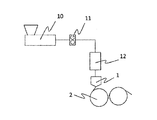
- FIG. 1 is a schematic view of a polyolefin resin sheet manufacturing apparatus according to an embodiment of the present invention.
- a sheet manufacturing apparatus cools and solidifies a base 1 for discharging a resin melted by an extruder into a sheet and a sheet 3 discharged from the base 1 while picking up and conveying the base 3.
- the cast cooling device 2 is provided. The discharged sheet is cast on the surface of the traveling cast cooling device. Further, when the sheet containing the diluent is cooled by the cast cooling device, at least a diluent such as liquid paraffin remains on the cast surface after the sheet is separated from the cast cooling device.
- the cast cooling device may be a roll or a belt, and the scraping device may be a rubber plate scraper or a resin doctor blade.
- a decompression chamber 4 having a shape along the outer peripheral surface of the cast cooling device 2 is adjacent to the base 1 on the back side of the base 1, that is, on the upstream side in the sheet conveying direction from the landing point of the sheet 3 on the cast surface. Is provided.
- a negative pressure region is generated on the back side of the sheet 3, that is, on the surface side where the sheet 3 contacts the cast cooling device 2.
- the decompression chamber body 4 has an opening and a decompression chamber, and the opening is formed over the entire width of the sheet in the immediate vicinity of the portion where the sheet 3 starts to adhere to the outer peripheral surface of the cast cooling device 2.
- the air in the decompression chamber is sucked by the suction device, and accordingly, the air in the close contact portion between the sheet and the cast cooling device 2 is sucked from the opening of the decompression chamber body 4.
- the contact portion is depressurized, and the air caught between the sheet and the cast cooling device 2 is excluded.
- the degree of decompression to a predetermined value, the molten resin sheet 3 can be stably adhered to the cast cooling device 2.
- This decompression chamber constitutes a close contact means.
- the degree of decompression in the decompression chamber body 4 is preferably controlled to a predetermined value according to the film forming conditions such as the viscosity of the molten resin, the thickness of the sheet, and the sheet conveyance speed of the cast cooling device.
- the suction pressure with respect to the atmospheric pressure in the decompression chamber body 4 is preferably in the range of ⁇ 2500 Pa to ⁇ 20 Pa.
- the lower limit of the suction pressure with respect to the atmospheric pressure in the decompression chamber body 4 is more preferably ⁇ 1500 Pa or more, and the upper limit is more preferably ⁇ 50 Pa or less.
- the air sucked by the decompression chamber 4 contains a low molecular weight component contained in the sheet, a gas of a volatile component from a diluent having high evaporation and condensation properties, and a particulate liquefied product.
- This volatile component is likely to condense as the temperature decreases.
- the device can be easily used regardless of whether the object to be contacted is a heated body. Adhere to. When a certain amount of the adhering material accumulates, it drops and contaminates the cast cooling device surface 2 and contaminates the surface of the sheet facing the cast cooling device.
- the sheet manufacturing apparatus of the present invention also includes means for preventing such contamination.
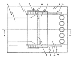
- FIG. 2 is a top view of FIG. 1
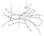
- FIG. 3 is a side view of FIG. 1
- FIG. 4 is a cross-sectional view along AA of FIG.
- the decompression chamber main body 4 when the decompression chamber main body 4 is fixed at a predetermined position, the decompression chamber main body 4 is prevented from entering excess air into the decompression chamber main body 4 during suction.
- the surface facing the cast cooling device 2 is disposed at a position slightly away from the cast cooling device 2.
- a sealing material 7b for preventing the inflow of air from this slight gap is provided on the peripheral portion of this surface of the decompression chamber body 4. This sealing material is sandwiched between the side plate and the pressing plate of the decompression chamber body 4 and is fastened and fixed by bolts at predetermined intervals.
- the above-mentioned attachment method is an example and you may employ
- a groove may be provided on the surface of the decompression chamber body 4 facing the cast cooling device 2 and a sealing material may be embedded in the groove.
- a groove may be provided in the sealing material 7b and fitted into the housing of the decompression chamber main body 4.
- a bolt fixing hole may be provided in the sealing material 7b, and the bolt may be fixed with a bolt hole provided on the surface of the decompression chamber body 4 facing the cast cooling device 2.
- the diluent remains on the cast surface, and even if a scraping device is used, the cast surface layer is still a thin diluent liquid.
- the film remains.
- wear of the seal material and scratches on the cast surface due to biting into the seal material such as abrasion powder occur, but this remaining thin liquid film improves friction by reducing the sliding property of the seal material. It is possible to prevent the sealing material from being damaged.
- the air flow inside the decompression chamber is rectified, and dripping due to fluctuations in the air flow of droplets such as diluent deposited inside can be prevented.
- the sealing material 7b is preferably a porous resin or rubber that has a small compressive load and can ensure the sealing performance of the sealing surface with a low load.
- the rubber material foams of NBR, CR, MSR, fluorine, butyl, urethane, and silicon are preferable, and foams of closed cells are more preferable.
- it is a non-conductive silicone sponge rubber that does not impart conductivity to the product even if wear powder is mixed into the product.
- the hardness is preferably Shore E10 to 35, which can provide sealability with a low load. More preferably, the shores E25 to 35 have a small deformation amount of the contact surface even when subjected to a shearing force due to the rotation of the cast cooling device.
- the pressing force of the sealing material 7b to the cast cooling device 2 is preferably 0.3 kgf or more in order to maintain the sealing performance even under reduced pressure. It is preferable to secure 0.5 mm or more for the amount of crushing of the sealing material 7b to the cast cooling device 2 in order to prevent deterioration of the sealing performance due to wear during film formation. More preferably, the thickness is 0.5 to 1.5 mm in order to suppress the shape change of the crushing allowance.
- a sealing material 7 a that contacts the base 1 is disposed on the downstream edge of the upper plate 4 a of the decompression chamber body 4 in the transport direction.
- the sealing material 7a is preferably porous resin or rubber.
- the above-mentioned attachment method is an example and you may employ
- the edge of the upper plate 4a may be attached to the base 1 body by welding, and the edge of the base 1 and the upper plate 4a may be fixedly installed by a bracket. Alternatively, it may be configured integrally with the base 1.
- the partition plate 5 is preferably formed in a plate shape so as to extend in the width direction of the sheet, and is formed from one side plate to the other side plate in the decompression chamber 4 so as to close the vicinity of the opening. Further, the partition plate 5 is disposed so that there is a space between the upper surface of the partition plate 5 and the lower surface of the base 1, and the gap is preferably 1 mm or more, and more preferably 5 mm or more. The air sucked from the opening of the decompression chamber 4 stays in a vortex in a space formed by the base 1, the partition plate 5 and the sheet. This stagnation of air leads to sheet fluctuation. By making a gap between the upper surface of the partition plate 5 and the lower surface of the base 1, it is possible to prevent air from staying.
- the partition plate 5 it is preferable to arrange the partition plate 5 so that there is a space between the lower surface of the partition plate 5 and the cast cooling device 2 surface, and the gap is preferably 1 mm or more, and more preferably 5 mm or more. preferable.
- the partition plate 5 is preferably located 1 to 10 mm upstream from the base lip in the sheet conveying direction, and more preferably 1 to 5 mm. Thereby, the space area formed with the partition plate 5, the sheet
- Rectifying plates 6 installed so as to close the gap with the device 2 are provided at both ends of the base in the width direction.
- the side plate of the base 1 is provided with a screw hole.
- the rectifying plate 6 is held by the bracket 13 and is attached to the base 1 by passing a bolt through a hole provided in the bracket 13 and tightening it in a screw hole of the base side plate.
- the above-mentioned attachment method is an example and you may employ
- the bracket 13 may be attached to the decompression chamber body 4.
- the decompression chamber 4 or the base 1 and the bracket may be used.
- the upper plate 4a of the decompression chamber body 4 is inclined downward from the horizontal toward the upstream side in the sheet conveying direction.
- the inclination angle is preferably 5 degrees or more, more preferably 10 degrees or more, downward from the horizontal direction over the entire upper plate 4a. This forcibly induces the droplets that condense or adhere to the receiving plate 9 described later to prevent the droplets from staying on the upper plate.
- the flow velocity of the droplet becomes slower in that portion, and the droplet flowing from the downstream side in the sheet conveyance direction catches up. A droplet grows and it becomes easy to drop a droplet.
- the inclination angle is constant or increases toward the upstream side in the transport direction.
- the lower surface edge of the upper plate 4a downstream in the sheet conveying direction is continuous with the extension of the lower surface of the lip of the base.
- it is preferable to increase the surface energy because the lower surface of the upper plate 4a corresponding to the reduced pressure region side inhibits the liquid from growing into a liquid pool that drops.
- the surface of the upper plate on the decompression region side is roughened by sandblasting.
- the surface roughness is preferably in accordance with JIS B0601-1994, centerline average roughness (Ra): 0.2 to 20 ⁇ m, and ten-point average height (Rz): 1 to 120 ⁇ m.
- the method described above is an example, and a method different from the method described above may be employed. For example, there is a method of improving the familiarity between the casing surface of the decompression chamber and the liquid droplets by applying hydrophilic treatment to the lipophilic oil and the comb.
- a plurality of suction ports are provided in the upstream portion of the upper plate of the decompression chamber body 4 in order to make the suction air uniform in the sheet width direction, and the air from each suction port is provided between the suction port and the suction device.
- a valve is provided for adjusting the amount.
- the suction device for sucking the air inside the decompression chamber body 4 may be a blower or a vacuum pump.
- a receiving plate 9 that extends from the upper plate 4a and extends over the entire width of the nozzle is provided below the suction port of the decompression chamber.
- the shape of the receiving plate 9 is preferably U-shaped.
- the U shape may be a shape having at least two bending points from the upper plate, a curved shape such as a C shape, or a shape combining these two shapes. Good.
- it is preferable that at least a part of the surface facing the cast surface is upward from the horizontal toward the downstream side in the sheet conveyance direction.
- the surface of the receiving plate 9 facing the cast cooling device 2 is longer downstream in the sheet conveying direction than directly below the suction port.
- the suction pressure from the atmospheric pressure is greatly reduced in the decompression chamber as the speed increases, and the volatilization of the diluent and the like from the back of the sheet becomes excessive, and the number of droplets attached to the decompression chamber increases.
- the resin supplied to the die 1 may be a polyolefin solution resin prepared by mixing a polyolefin resin such as polyethylene, polypropylene, polystyrene, or polymethylpentene with a diluent and heating and melting the resin.
- the diluent determines the structure for microporous formation of the microporous plastic film, and also improves the stretchability when stretching the film (for example, reduction of plaque at the stretch ratio for strength development). Contribute.
- the diluent is not particularly limited as long as it is a substance that can be mixed or dissolved in the polyolefin resin. In the melt-kneaded state, it is miscible with the polyolefin, but a solid solvent may be mixed with the diluent at room temperature. Examples of such a solid diluent include stearyl alcohol, seryl alcohol, and paraffin wax.
- the diluent is preferably a liquid at room temperature in order to prevent unevenness in stretching and to be applied later.
- Liquid diluents include nonane, decane, decalin, paraxylene, undecane, dodecane, liquid paraffins and other aliphatic, cycloaliphatic or aromatic hydrocarbons, and mineral oils with boiling points in the range of these compounds.
- a phthalic acid ester which is liquid at room temperature such as a distillate and dibutyl phthalate or dioctyl phthalate can be mentioned.
- liquid paraffin In order to obtain a gel-like sheet having a stable liquid diluent content, it is more preferable to use liquid paraffin.
- the viscosity of the liquid diluent is preferably 20 to 200 cSt at 40 ° C.
- the blending ratio of the polyolefin resin and the diluent is preferably 10 to 50% by mass from the viewpoint of improving the extrudate moldability by setting the total of the polyolefin resin and the diluent to 100% by mass.
- the uniform melt-kneading process of a polyolefin solution is not specifically limited, A calendar, various mixers, an extruder with a screw, etc. are mentioned.
- Example 1 The specific sheet manufacturing method in the present embodiment is as follows.
- Sheet material High density polyethylene (HDPE), viscosity 1000 Pa ⁇ s.
- the viscosity was measured by the method of JIS K7117-2 under the conditions of a shear rate of 100 / s and a temperature of 200 ° C. -Liquid paraffin (LP), kinematic viscosity 51 cSt (at 40 ° C. mm 2 / s).
- Cast cooling device A mirror sheet forming roll was used as a cast cooling device. After extruding into a sheet form from the sheet forming die, the roll temperature was set to 35 ° C. with a cooling roll, and then molded at a casting speed of 3 m / min.
- Depressurization chamber The clearance between the sheet forming die and the sheet forming roll was 40 mm, and the inclination angle of the upper plate of the depressurization chamber was constant at 10 degrees downward from the horizontal direction over the entire upper plate. As shown in FIG. 2, the installation position of the rectifying plate was adjusted so as to be an extension of the side surface of the decompression chamber main body, and the lip position of the base was arranged on the top of the roll, and then the decompression chamber was installed. Expanded PTFE was used as the sealing material with the die, and silicon sponge rubber: hardness (type E) 30 degrees, non-conductive was used as the sealing material with the cast surface. The degree of vacuum was set to -100 Pa with respect to atmospheric pressure.
- the “thickness unevenness R” is a ratio obtained by dividing a value obtained by subtracting the minimum sheet thickness from the maximum sheet thickness in the sheet conveyance direction by the average sheet thickness.
- the “horizontal dan” means that the sheet discharged from the base is subjected to air vibrations due to the influence of the surrounding air current due to suction in the decompression chamber before landing on the cast cooling device. It means that periodic thickness unevenness occurs in the sheet conveying direction. This unevenness in thickness is a problem in quality because the visibility is high and conspicuous as a streak that runs in the sheet conveyance direction in the sheet conveyance direction on the sheet surface.
- Example 2 The specific sheet manufacturing method in the present embodiment is as follows.
- Sheet material The same material as in Example 1 was used.
- Preparation Example 1 was the same as Example 1 except that the apparatus temperature up to the die was set to 200 ° C.
- Sheet forming die Using a base with a slit width of 300 mm, the resin was discharged at a flow rate of 250 kg / hr. The LP concentration in the resin is 70% by mass, and 175 kg / hr is LP. As described above, LP of about 0.1% of the resin flow rate is volatilized from the sheet, and about 6.0 kg of volatile LP per day is sucked into the decompression chamber together with the surrounding air.
- Cast cooling device The same as Example 1 except that the casting speed was 10 m / min.
- Vacuum chamber The same vacuum chamber as in Example 1 was used. The degree of vacuum was set to ⁇ 500 Pa with respect to atmospheric pressure.
- Example 3 The specific sheet manufacturing method in the present embodiment is as follows. (1) Sheet material: The same material as in Example 1 was used. (2) Preparation: Example 1 was the same as Example 1 except that the apparatus temperature up to the die was set to 200 ° C. (3) Sheet forming die: A base having a slit width of 400 mm was used. The resin was discharged from the base at a flow rate of 300 kg / hr. The LP concentration in the resin is 70% by mass, and 210 kg / hr is LP. Further, as described above, about 0.1% of the resin flow rate is volatilized from the sheet, and about 7.2 kg of volatile LP is sucked into the decompression chamber together with the ambient air in one day.
- Example 2 The same as Example 1 except that the casting speed was 16 m / min.
- Decompression chamber The same depressurization chamber as in Example 1 was used except that the depressurized region surface was roughened by a sand blaster. The degree of vacuum was set to -1200 Pa with respect to atmospheric pressure.
- Example 1 The specific sheet manufacturing method in the present embodiment is as follows.
- Sheet material The same material as in Example 1 was used.
- Preparation Example 1 was the same as Example 1 except that the apparatus temperature up to the die was set to 220 ° C.
- Sheet forming die Using a die with a slit width of 300 mm, the resin was discharged at a flow rate of 100 kg / hr.
- the LP concentration in the resin is 70% by mass, and 70 kg / hr is LP. Further, as described above, about 0.1% of the resin flow rate is volatilized from the sheet, and about 2.4 kg of volatile LP is sucked into the decompression chamber together with the ambient air in one day.
- Cast cooling device Same as Example 1. (5) Vacuum chamber No vacuum chamber was installed.
- Example 2 The specific sheet manufacturing method in the present embodiment is as follows.
- Sheet material The same material as in Example 1 was used.
- Preparation Example 1 was the same as Example 1 except that the apparatus temperature up to the die was set to 220 ° C.
- Sheet forming die Using a die with a slit width of 300 mm, the resin was discharged at a flow rate of 100 kg / hr. The LP concentration in the resin is 70% by mass, and 70 kg / hr is LP. Further, as described above, about 0.1% of the resin flow rate is volatilized from the sheet, and about 2.4 kg of volatile LP is sucked into the decompression chamber together with the ambient air in one day.
- Cast cooling device Same as Example 1.
- Depressurization chamber It was the same as Example 3 except that the current plate was not installed. The degree of vacuum was set to ⁇ 600 Pa with respect to atmospheric pressure.
- Example 3 The specific sheet manufacturing method in the present embodiment is as follows.
- Sheet material The same material as in Example 1 was used.
- Preparation Example 1 was the same as Example 1 except that the apparatus temperature up to the die was set to 220 ° C.
- Sheet forming die Using a die with a slit width of 300 mm, the resin was discharged at a flow rate of 100 kg / hr. The LP concentration in the resin is 70% by mass, and 70 kg / hr is LP. Further, as described above, about 0.1% of the resin flow rate is volatilized from the sheet, and about 2.4 kg of volatile LP is sucked into the decompression chamber together with the ambient air in one day.
- Cast cooling device Same as Example 1.
- Depressurization chamber Same as Example 3 except that no partition plate was installed. The degree of vacuum was set to ⁇ 1100 Pa with respect to atmospheric pressure.
- Example 4 The specific sheet manufacturing method in the present embodiment is as follows. (1) Sheet material: The same material as in Example 1 was used. (2) Preparation: Example 1 was the same as Example 1 except that the apparatus temperature up to the die was set to 220 ° C. (3) Sheet forming die: Using a slit width of 300 mm, the resin was discharged at a flow rate of 100 kg / hr. The LP concentration in the resin is 70% by mass, and 70 kg / hr is LP. Further, as described above, about 0.1% of the resin flow rate is volatilized from the sheet, and about 2.4 kg of volatile LP is sucked into the decompression chamber together with the ambient air in one day. (4) Cast cooling device: Same as Example 1. (5) Decompression chamber It was the same as Example 3 except that no sealant was installed between the rolls. The degree of decompression was set to ⁇ 1700 Pa with respect to atmospheric pressure.
- the present invention can be applied not only to a polyolefin resin sheet manufacturing method but also to a solution resin sheet manufacturing method and die coating, but the application range is not limited thereto.
Landscapes
- Engineering & Computer Science (AREA)
- Mechanical Engineering (AREA)
- Chemical & Material Sciences (AREA)
- Thermal Sciences (AREA)
- Physics & Mathematics (AREA)
- Manufacturing & Machinery (AREA)
- Organic Chemistry (AREA)
- Polymers & Plastics (AREA)
- Medicinal Chemistry (AREA)
- Chemical Kinetics & Catalysis (AREA)
- Health & Medical Sciences (AREA)
- Materials Engineering (AREA)
- Extrusion Moulding Of Plastics Or The Like (AREA)
- Moulding By Coating Moulds (AREA)
- Coating Apparatus (AREA)
- Application Of Or Painting With Fluid Materials (AREA)
Abstract
Description
「長手方向」とはシートの長手方向を指し、「幅方向」とはシートの幅方向を指し、「上流」とはキャストシートの搬送方向における上流を指す。
「下流」とはキャストシートの搬送方向における下流をいう。
「減圧チャンバ本体のキャスト冷却装置と対向する面」とは、減圧チャンバの筐体においてキャスト冷却装置との間で筐体周囲部分の空気の流入が発生し得る間隙(ただし、シート上流部の減圧チャンバ開口部を除く)のキャスト冷却装置面に対向する筐体側の面をいう。
本実施形態における具体的なシートの製造方法は以下のとおりである。
・高密度ポリエチレン(HDPE)、粘度1000Pa・s。ここで、粘度は、せん断速度100/s、温度200℃の条件で、JIS K7117-2の方法で測定した。
・流動パラフィン(LP)、動粘度51cSt(40℃mm2/sのとき)。
シート材料を乾燥後、押出機に供給し、ギアポンプ、フィルターを介した後に、シート成形口金に供給した。また、口金に至るまでの装置温度は230℃に設定した。
スリット幅300mmの口金を使用し、上記樹脂を流量70kg/hrで吐出させた。
なお樹脂中のLP濃度は70質量%とし、49kg/hrがLPである。またシート幅、および減圧度にもよるがシートからは樹脂流量の約0.1%のLPが揮発しており、1日で約1.7kgの揮発LPが減圧チャンバの内部に周辺空気とともに吸引されている。
キャスト冷却装置として、鏡面のシート成形ロールを使用した。シート成形口金からシート状に押出した後、冷却ロールでロール温度を35℃に設定した上で、キャスト速度3m/分で成形した。
シート成形口金とシート成形ロール間のクリアランスを40mm、減圧チャンバの上部板の傾斜角度を上部板全体にわたって水平方向から下向きに10度で一定としたものを使用した。整流板は図2に示すように減圧チャンバ本体の側面の延長上になるよう設置位置を調整し、さらに口金のリップ位置をロールの頂上に配した上で、減圧チャンバを設置した。口金とのシール材は延伸PTFEを使用し、またキャスト面とのシール材にはシリコンスポンジゴム:硬度(タイプE)30度、非導電性のものを使用した。また減圧度は大気圧に対して-100Paになるように設定した。
本実施形態における具体的なシートの製造方法は以下のとおりである。
(1)シート材料:
実施例1と同じ材料を使用した。
(2)仕込み:
口金に至るまでの装置温度を200℃に設定した以外は、実施例1と同じとした。
(3)シート成形口金:
スリット幅300mmの口金を使用し、上記樹脂を流量250kg/hrで吐出させた。なお樹脂中のLP濃度は70質量%とし、175kg/hrがLPである。また先述したようにシートからは樹脂流量の約0.1%のLPが揮発しており、1日で約6.0kgの揮発LPが減圧チャンバの内部に周辺空気とともに吸引されている。
(4)キャスト冷却装置:
キャスト速度を10m/分にした以外は実施例1と同じとした。
(5)減圧チャンバ
実施例1と同じ減圧チャンバを使用した。また減圧度は大気圧に対して-500Paになるように設定した。
本実施形態における具体的なシートの製造方法は以下のとおりである。
(1)シート材料:
実施例1と同じ材料を使用した。
(2)仕込み:
口金に至るまでの装置温度を200℃に設定した以外は、実施例1と同じとした。
(3)シート成形口金:
スリット幅400mmの口金を使用した。口金から上記樹脂を流量300kg/hrで吐出させた。なお樹脂中のLP濃度は70質量%とし、210kg/hrがLPである。また先述したようにシートからは樹脂流量の約0.1%のLPが揮発しており、1日で約7.2kgの揮発LPが減圧チャンバの内部に周辺空気とともに吸引されている。
(4)キャスト冷却装置:
キャスト速度を16m/分にした以外は実施例1と同じとした。
(5)減圧チャンバ
減圧領域面がサンドブラスターにより粗面化されている以外は、実施例1と同じ減圧チャンバを使用した。また減圧度は大気圧に対して-1200Paになるように設定した。
本実施形態における具体的なシートの製造方法は以下のとおりである。
(1)シート材料:
実施例1と同じ材料を使用した。
(2)仕込み:
口金に至るまでの装置温度を220℃に設定した以外は、実施例1と同じとした。
(3)シート成形口金:
スリット幅300mmの口金を使用し、上記樹脂を流量100kg/hrで吐出させた。なお樹脂中のLP濃度は70質量%とし、70kg/hrがLPである。また先述したようにシートからは樹脂流量の約0.1%のLPが揮発しており、1日で約2.4kgの揮発LPが減圧チャンバの内部に周辺空気とともに吸引されている。
(4)キャスト冷却装置:
実施例1と同じとした。
(5)減圧チャンバ
減圧チャンバは設置しなかった。
本実施形態における具体的なシートの製造方法は以下のとおりである。
(1)シート材料:
実施例1と同じ材料を使用した。
(2)仕込み:
口金に至るまでの装置温度を220℃に設定した以外は、実施例1と同じとした。
(3)シート成形口金:
スリット幅300mmの口金を使用し、上記樹脂を流量100kg/hrで吐出させた。
なお樹脂中のLP濃度は70質量%とし、70kg/hrがLPである。また先述したようにシートからは樹脂流量の約0.1%のLPが揮発しており、1日で約2.4kgの揮発LPが減圧チャンバの内部に周辺空気とともに吸引されている。
(4)キャスト冷却装置:
実施例1と同じとした。
(5)減圧チャンバ
整流板を設置しない以外は実施例3と同じとした。また減圧度は大気圧に対して-600Paになるように設定した。
本実施形態における具体的なシートの製造方法は以下のとおりである。
(1)シート材料:
実施例1と同じ材料を使用した。
(2)仕込み:
口金に至るまでの装置温度を220℃に設定した以外は、実施例1と同じとした。
(3)シート成形口金:
スリット幅300mmの口金を使用し、上記樹脂を流量100kg/hrで吐出させた。
なお樹脂中のLP濃度は70質量%とし、70kg/hrがLPである。また先述したようにシートからは樹脂流量の約0.1%のLPが揮発しており、1日で約2.4kgの揮発LPが減圧チャンバの内部に周辺空気とともに吸引されている。
(4)キャスト冷却装置:
実施例1と同じとした。
(5)減圧チャンバ
仕切り板を設置しない以外は実施例3と同じとした。また減圧度は大気圧に対して-1100Paになるように設定した。
本実施形態における具体的なシートの製造方法は以下のとおりである。
(1)シート材料:
実施例1と同じ材料を使用した。
(2)仕込み:
口金に至るまでの装置温度を220℃に設定した以外は、実施例1と同じとした。
(3)シート成形口金:
スリット幅300mmを使用し、上記樹脂を流量100kg/hrで吐出させた。
なお樹脂中のLP濃度は70質量%とし、70kg/hrがLPである。また先述したようにシートからは樹脂流量の約0.1%のLPが揮発しており、1日で約2.4kgの揮発LPが減圧チャンバの内部に周辺空気とともに吸引されている。
(4)キャスト冷却装置:
実施例1と同じとした。
(5)減圧チャンバ
ロールとの間のシール材を設置しない以外は実施例3と同じとした。また減圧度は大気圧に対して-1700Paになるように設定した。
2 キャスト冷却装置
3 シート
4 減圧チャンバ本体
4a 上部板
4b 側面板
5 仕切板
6 整流板
7 シール材
7a シール材(口金部)
7b シール材(キャスト冷却装置部)
8 押え板
9 受け板
10 押出機
11 ギアポンプ
12 フィルター
13 ブラケット
14 シートとキャスト冷却装置間の隙間
15 減圧チャンバとキャスト冷却装置間の隙間
16 タッチロール
17 掻き取り装置
Claims (5)
- ポリオレフィン樹脂と希釈剤とが混合された樹脂をシート状に吐出するための口金と、
前記口金から吐出されるシートを搬送しながら冷却し固化するためのキャスト冷却装置と、
前記口金よりも前記キャスト冷却装置の搬送方向上流側に設置され、前記口金から吐出される前記シートと前記キャスト冷却装置との間の空気を吸引するための減圧チャンバと、を備えた微多孔ポリオレフィン樹脂シートの製造装置であって、
前記口金のリップよりも前記キャスト冷却装置の搬送方向下流で、このリップから吐出されるシートの幅方向端部よりも外側に、前記口金から吐出されるシートとキャスト面との隙間を塞ぐように設置された整流板をさらに備え、
前記減圧チャンバは、前記キャスト冷却装置と対向する面の少なくとも周囲部分に設けられキャスト冷却装置と物理的に接触するシール材と、口金に対向する開口部近傍にシート幅方向にわたって設けられた仕切板と、を備えた微多孔ポリオレフィン樹脂シートの製造装置。 - 前記減圧チャンバ本体が、前記キャスト冷却装置の搬送方向上流側に向けて水平より下向きに傾斜している上部板であって水平方向に対するその傾斜角度が一定または前記キャスト冷却装置の搬送方向上流側に向かうにつれて大きくなっている前記上部板と、前記減圧チャンバ本体の吸引口の下部に前記上部板から連なり前記減圧チャンバ本体全幅にわたる受け板と、を備えた、請求項1に記載の微多孔ポリオレフィン樹脂シート製造装置。
- 前記シール材が多孔質の樹脂またはゴムである、請求項1または2に記載の微多孔ポリオレフィン樹脂シートの製造装置。
- 請求項1~3のいずれか一項に記載の微多孔ポリオレフィン樹脂シート製造装置を用い、
前記口金から溶融樹脂を前記キャスト冷却装置上にシート状に吐出し、
前記口金から吐出されたシートと前記キャスト冷却装置との間の空気を前記減圧チャンバ本体で吸引して、前記シートと前記キャスト冷却装置とを密着させ、
前記シートを前記キャスト冷却装置により搬送しながら冷却して固化させる、微多孔ポリオレフィン樹脂シート製造方法。 - ポリオレフィン樹脂と希釈剤とが混合された樹脂を口金からシート状に吐出し、
前記口金から吐出されたシートをキャスト冷却装置により搬送速度3m/分以上で搬送しながら冷却固化し、
前記口金よりも前記キャスト冷却装置の搬送方向上流側において、前記口金から吐出された前記シートと前記キャスト冷却装置との間の空気を吸引するための減圧チャンバ本体により前記シートを前記キャスト冷却装置に密着させる、微多孔ポリオレフィン樹脂シート製造方法。
Priority Applications (4)
| Application Number | Priority Date | Filing Date | Title |
|---|---|---|---|
| JP2016533218A JP6047264B1 (ja) | 2015-02-04 | 2016-01-07 | 微多孔ポリオレフィン樹脂シートの製造装置および製造方法 |
| EP16746357.9A EP3130446B1 (en) | 2015-02-04 | 2016-01-07 | Device and method for producing microporous polyolefin resin sheet |
| CN201680002225.8A CN106794617B (zh) | 2015-02-04 | 2016-01-07 | 微多孔聚烯烃树脂薄片的制造装置和制造方法 |
| KR1020167030696A KR101716341B1 (ko) | 2015-02-04 | 2016-01-07 | 미세 다공 폴리올레핀 수지 시트의 제조 장치 및 제조 방법 |
Applications Claiming Priority (2)
| Application Number | Priority Date | Filing Date | Title |
|---|---|---|---|
| JP2015019864 | 2015-02-04 | ||
| JP2015-019864 | 2015-02-04 |
Publications (1)
| Publication Number | Publication Date |
|---|---|
| WO2016125526A1 true WO2016125526A1 (ja) | 2016-08-11 |
Family
ID=56563877
Family Applications (1)
| Application Number | Title | Priority Date | Filing Date |
|---|---|---|---|
| PCT/JP2016/050396 Ceased WO2016125526A1 (ja) | 2015-02-04 | 2016-01-07 | 微多孔ポリオレフィン樹脂シートの製造装置および製造方法 |
Country Status (6)
| Country | Link |
|---|---|
| EP (1) | EP3130446B1 (ja) |
| JP (1) | JP6047264B1 (ja) |
| KR (1) | KR101716341B1 (ja) |
| CN (1) | CN106794617B (ja) |
| HU (1) | HUE042687T2 (ja) |
| WO (1) | WO2016125526A1 (ja) |
Cited By (8)
| Publication number | Priority date | Publication date | Assignee | Title |
|---|---|---|---|---|
| JP2018144480A (ja) * | 2017-03-03 | 2018-09-20 | 住友化学株式会社 | フィルム製造装置およびフィルム製造方法 |
| JP2020037235A (ja) * | 2018-09-05 | 2020-03-12 | 東レ株式会社 | 減圧チャンバー、キャスト冷却装置、樹脂シートの製造装置及び樹脂シートの製造方法 |
| WO2020137530A1 (ja) | 2018-12-26 | 2020-07-02 | 東レ株式会社 | シートの製造方法、ポリオレフィン微多孔膜の製造方法、混練計量装置及び吐出装置 |
| CN112238589A (zh) * | 2019-07-18 | 2021-01-19 | 布鲁克纳机械有限责任两合公司 | 用于制造熔体膜和/或塑料膜的方法和设备 |
| CN113459370A (zh) * | 2021-06-16 | 2021-10-01 | 广东金明精机股份有限公司 | 薄膜拉伸厚度控制方法 |
| WO2022168546A1 (ja) * | 2021-02-08 | 2022-08-11 | 東レ株式会社 | 微多孔ポリオレフィン樹脂シートの製造方法および微多孔ポリオレフィン樹脂シートの製造装置 |
| JP2023020052A (ja) * | 2021-07-30 | 2023-02-09 | 東レ株式会社 | 微多孔ポリオレフィン樹脂シートの製造方法および製造装置 |
| WO2025100108A1 (ja) | 2023-11-06 | 2025-05-15 | 東レ株式会社 | 微多孔ポリオレフィン樹脂シートの製造装置および微多孔ポリオレフィン樹脂シートの製造方法 |
Families Citing this family (4)
| Publication number | Priority date | Publication date | Assignee | Title |
|---|---|---|---|---|
| KR20180093559A (ko) | 2017-02-14 | 2018-08-22 | 에스케이씨 주식회사 | 고분자 필름 제조를 위한 고속 캐스팅 방법 |
| CN112659432B (zh) * | 2021-01-21 | 2022-08-23 | 扬州苏伟新材料科技有限公司 | 一种聚酰亚胺薄膜流涎机补偿进风装置 |
| KR102487448B1 (ko) * | 2022-11-15 | 2023-01-11 | (주)오성기업 | 이형지 엣지 코팅액 스크래퍼 장치를 구비하는 이형지 제조장치 |
| CN120268312B (zh) * | 2025-06-06 | 2025-08-12 | 山东河清化工科技有限公司 | 一种无水哌嗪结片装置及其结片方法 |
Citations (2)
| Publication number | Priority date | Publication date | Assignee | Title |
|---|---|---|---|---|
| JP2004508979A (ja) * | 2000-09-24 | 2004-03-25 | スリーエム イノベイティブ プロパティズ カンパニー | 微孔性フィルムを製造するための押出方法および装置 |
| JP2012500130A (ja) * | 2008-08-15 | 2012-01-05 | 東レ東燃機能膜合同会社 | 微多孔膜の製造方法および微多孔膜の製造装置 |
Family Cites Families (13)
| Publication number | Priority date | Publication date | Assignee | Title |
|---|---|---|---|---|
| US3579735A (en) * | 1967-07-31 | 1971-05-25 | Crown Zellerbach Corp | Apparatus for balancing pressure applied to film-forming material in the deposition thereof onto a casting surface |
| US4310295A (en) * | 1981-01-28 | 1982-01-12 | E. I. Du Pont De Nemours And Company | Device for uniform web pinning |
| FR2698580B1 (fr) * | 1992-12-01 | 1995-02-24 | Albert Plastiques | Dispositif pour plaquer sur un cylindre de refroidissement le film sortant d'une filière plate. |
| US5618568A (en) * | 1995-02-01 | 1997-04-08 | Extrusion Dies, Inc. | Dual-chamber vacuum box |
| ID20180A (id) * | 1997-04-21 | 1998-10-22 | Mitsubishi Heavy Ind Ltd | Peralatan pencetakan untuk pembentukan membran yang dibuat dari resin |
| JP2000225627A (ja) | 1999-02-08 | 2000-08-15 | Toray Ind Inc | フイルムの製造装置 |
| JP2002096370A (ja) * | 2000-09-26 | 2002-04-02 | Toray Ind Inc | 口金、シートならびにその製造装置および製造方法 |
| JP4464582B2 (ja) | 2001-05-30 | 2010-05-19 | 株式会社日本製鋼所 | 樹脂シートの製造方法及び樹脂シート成形用キャスティング装置 |
| JP2008188941A (ja) | 2007-02-07 | 2008-08-21 | Fujifilm Corp | 溶液製膜方法及び溶液製膜設備 |
| JP5312450B2 (ja) * | 2007-08-31 | 2013-10-09 | 東レバッテリーセパレータフィルム株式会社 | ポリオレフィン多層微多孔膜、その製造方法、電池用セパレータ及び電池 |
| CN102744851A (zh) * | 2011-04-20 | 2012-10-24 | 住友化学株式会社 | 结晶性树脂薄膜制造方法和结晶性树脂薄膜制造装置 |
| JP2013212673A (ja) | 2012-04-04 | 2013-10-17 | Japan Steel Works Ltd:The | セパレータフィルムの湿式製造装置及び方法 |
| JP6217744B2 (ja) * | 2013-03-12 | 2017-10-25 | コニカミノルタ株式会社 | 樹脂フィルムの製造方法 |
-
2016
- 2016-01-07 CN CN201680002225.8A patent/CN106794617B/zh active Active
- 2016-01-07 HU HUE16746357A patent/HUE042687T2/hu unknown
- 2016-01-07 EP EP16746357.9A patent/EP3130446B1/en active Active
- 2016-01-07 KR KR1020167030696A patent/KR101716341B1/ko active Active
- 2016-01-07 JP JP2016533218A patent/JP6047264B1/ja active Active
- 2016-01-07 WO PCT/JP2016/050396 patent/WO2016125526A1/ja not_active Ceased
Patent Citations (2)
| Publication number | Priority date | Publication date | Assignee | Title |
|---|---|---|---|---|
| JP2004508979A (ja) * | 2000-09-24 | 2004-03-25 | スリーエム イノベイティブ プロパティズ カンパニー | 微孔性フィルムを製造するための押出方法および装置 |
| JP2012500130A (ja) * | 2008-08-15 | 2012-01-05 | 東レ東燃機能膜合同会社 | 微多孔膜の製造方法および微多孔膜の製造装置 |
Non-Patent Citations (1)
| Title |
|---|
| See also references of EP3130446A4 * |
Cited By (17)
| Publication number | Priority date | Publication date | Assignee | Title |
|---|---|---|---|---|
| JP2018144480A (ja) * | 2017-03-03 | 2018-09-20 | 住友化学株式会社 | フィルム製造装置およびフィルム製造方法 |
| JP7234541B2 (ja) | 2018-09-05 | 2023-03-08 | 東レ株式会社 | 減圧チャンバー、キャスト冷却装置、樹脂シートの製造装置及び樹脂シートの製造方法 |
| JP2020037235A (ja) * | 2018-09-05 | 2020-03-12 | 東レ株式会社 | 減圧チャンバー、キャスト冷却装置、樹脂シートの製造装置及び樹脂シートの製造方法 |
| WO2020137530A1 (ja) | 2018-12-26 | 2020-07-02 | 東レ株式会社 | シートの製造方法、ポリオレフィン微多孔膜の製造方法、混練計量装置及び吐出装置 |
| KR20200118216A (ko) | 2018-12-26 | 2020-10-14 | 도레이 카부시키가이샤 | 시트의 제조 방법, 폴리올레핀 미다공막의 제조 방법, 혼련 계량 장치 및 토출 장치 |
| US11712832B2 (en) | 2019-07-18 | 2023-08-01 | Brückner Maschinenbau GmbH | Method and device for producing a melt and/or plastic film |
| CN112238589B (zh) * | 2019-07-18 | 2022-11-29 | 布鲁克纳机械有限责任两合公司 | 用于制造熔体膜和/或塑料膜的方法和设备 |
| JP2021017058A (ja) * | 2019-07-18 | 2021-02-15 | ブリュックナー・マシーネンバウ・ゲーエムベーハー・ウント・コー・カーゲー | 溶融薄膜及び/又は樹脂薄膜の製法と製造装置 |
| CN112238589A (zh) * | 2019-07-18 | 2021-01-19 | 布鲁克纳机械有限责任两合公司 | 用于制造熔体膜和/或塑料膜的方法和设备 |
| US11951668B2 (en) | 2019-07-18 | 2024-04-09 | Bruckner Maschinenbau Gmbh | Method and device for producing a melt and/or plastic film |
| WO2022168546A1 (ja) * | 2021-02-08 | 2022-08-11 | 東レ株式会社 | 微多孔ポリオレフィン樹脂シートの製造方法および微多孔ポリオレフィン樹脂シートの製造装置 |
| JPWO2022168546A1 (ja) * | 2021-02-08 | 2022-08-11 | ||
| JP7800418B2 (ja) | 2021-02-08 | 2026-01-16 | 東レ株式会社 | 微多孔ポリオレフィン樹脂シートの製造方法および微多孔ポリオレフィン樹脂シートの製造装置 |
| CN113459370A (zh) * | 2021-06-16 | 2021-10-01 | 广东金明精机股份有限公司 | 薄膜拉伸厚度控制方法 |
| JP2023020052A (ja) * | 2021-07-30 | 2023-02-09 | 東レ株式会社 | 微多孔ポリオレフィン樹脂シートの製造方法および製造装置 |
| JP7658208B2 (ja) | 2021-07-30 | 2025-04-08 | 東レ株式会社 | 微多孔ポリオレフィン樹脂シートの製造方法および製造装置 |
| WO2025100108A1 (ja) | 2023-11-06 | 2025-05-15 | 東レ株式会社 | 微多孔ポリオレフィン樹脂シートの製造装置および微多孔ポリオレフィン樹脂シートの製造方法 |
Also Published As
| Publication number | Publication date |
|---|---|
| EP3130446A1 (en) | 2017-02-15 |
| CN106794617B (zh) | 2018-06-05 |
| JP6047264B1 (ja) | 2016-12-21 |
| CN106794617A (zh) | 2017-05-31 |
| KR20160132124A (ko) | 2016-11-16 |
| EP3130446B1 (en) | 2018-11-14 |
| HUE042687T2 (hu) | 2019-07-29 |
| JPWO2016125526A1 (ja) | 2017-04-27 |
| EP3130446A4 (en) | 2017-06-07 |
| KR101716341B1 (ko) | 2017-03-14 |
Similar Documents
| Publication | Publication Date | Title |
|---|---|---|
| JP6047264B1 (ja) | 微多孔ポリオレフィン樹脂シートの製造装置および製造方法 | |
| US7169445B2 (en) | Method and apparatus for curtain coating | |
| US6982003B2 (en) | Method and apparatus for curtain coating | |
| CN106660253B (zh) | 微多孔聚烯烃树脂薄片的制造装置和制造方法 | |
| WO2015146580A1 (ja) | 微多孔プラスチックフィルムの製造方法 | |
| CN1147216A (zh) | 组合滚筒和印模涂层方法以及具有改进印模唇部的装置 | |
| US20150165470A1 (en) | Die coater and method for producing coated film | |
| CN101041153A (zh) | 涂敷液的涂敷方法、该方法所用的涂敷装置及其设计方法 | |
| CN105983511A (zh) | 涂布装置和涂布方法 | |
| JP7234541B2 (ja) | 減圧チャンバー、キャスト冷却装置、樹脂シートの製造装置及び樹脂シートの製造方法 | |
| US7867567B2 (en) | Coating method of coating solution | |
| JPH07114997B2 (ja) | 塗布方法 | |
| JPWO2018062028A1 (ja) | 熱可塑性樹脂フィルムの製造方法 | |
| JP6047265B1 (ja) | シート製造装置およびシート製造方法 | |
| KR20230138453A (ko) | 미다공 폴리올레핀 수지 시트의 제조 방법 및 미다공폴리올레핀 수지 시트의 제조 장치 | |
| JP2003053232A (ja) | 高粘度分散液の塗布装置及び塗布方法 | |
| JP2006272130A (ja) | 塗布液の塗布方法、塗布液の塗布装置、光学フィルム、および反射防止フィルム | |
| JP2014108555A (ja) | 光学フィルムの製造方法 | |
| JP5899916B2 (ja) | 薄膜の形成方法 | |
| JP6217676B2 (ja) | グリーンシートの成形装置 | |
| JPS61272123A (ja) | 厚さ精度の優れたポリエステルフィルムの製造方法 |
Legal Events
| Date | Code | Title | Description |
|---|---|---|---|
| ENP | Entry into the national phase |
Ref document number: 2016533218 Country of ref document: JP Kind code of ref document: A |
|
| 121 | Ep: the epo has been informed by wipo that ep was designated in this application |
Ref document number: 16746357 Country of ref document: EP Kind code of ref document: A1 |
|
| ENP | Entry into the national phase |
Ref document number: 20167030696 Country of ref document: KR Kind code of ref document: A |
|
| REEP | Request for entry into the european phase |
Ref document number: 2016746357 Country of ref document: EP |
|
| WWE | Wipo information: entry into national phase |
Ref document number: 2016746357 Country of ref document: EP |
|
| NENP | Non-entry into the national phase |
Ref country code: DE |