WO2016125575A1 - Ni合金鋳造品の製造方法及びNi合金鋳造品 - Google Patents
Ni合金鋳造品の製造方法及びNi合金鋳造品 Download PDFInfo
- Publication number
- WO2016125575A1 WO2016125575A1 PCT/JP2016/051361 JP2016051361W WO2016125575A1 WO 2016125575 A1 WO2016125575 A1 WO 2016125575A1 JP 2016051361 W JP2016051361 W JP 2016051361W WO 2016125575 A1 WO2016125575 A1 WO 2016125575A1
- Authority
- WO
- WIPO (PCT)
- Prior art keywords
- alloy
- casting
- crystal
- mold
- cobalt
- Prior art date
- Legal status (The legal status is an assumption and is not a legal conclusion. Google has not performed a legal analysis and makes no representation as to the accuracy of the status listed.)
- Ceased
Links
Images


Classifications
-
- B—PERFORMING OPERATIONS; TRANSPORTING
- B22—CASTING; POWDER METALLURGY
- B22D—CASTING OF METALS; CASTING OF OTHER SUBSTANCES BY THE SAME PROCESSES OR DEVICES
- B22D27/00—Treating the metal in the mould while it is molten or ductile ; Pressure or vacuum casting
- B22D27/20—Measures not previously mentioned for influencing the grain structure or texture; Selection of compositions therefor
-
- B—PERFORMING OPERATIONS; TRANSPORTING
- B22—CASTING; POWDER METALLURGY
- B22D—CASTING OF METALS; CASTING OF OTHER SUBSTANCES BY THE SAME PROCESSES OR DEVICES
- B22D21/00—Casting non-ferrous metals or metallic compounds so far as their metallurgical properties are of importance for the casting procedure; Selection of compositions therefor
- B22D21/002—Castings of light metals
- B22D21/005—Castings of light metals with high melting point, e.g. Be 1280 degrees C, Ti 1725 degrees C
-
- B—PERFORMING OPERATIONS; TRANSPORTING
- B22—CASTING; POWDER METALLURGY
- B22D—CASTING OF METALS; CASTING OF OTHER SUBSTANCES BY THE SAME PROCESSES OR DEVICES
- B22D27/00—Treating the metal in the mould while it is molten or ductile ; Pressure or vacuum casting
- B22D27/04—Influencing the temperature of the metal, e.g. by heating or cooling the mould
- B22D27/045—Directionally solidified castings
-
- C—CHEMISTRY; METALLURGY
- C22—METALLURGY; FERROUS OR NON-FERROUS ALLOYS; TREATMENT OF ALLOYS OR NON-FERROUS METALS
- C22C—ALLOYS
- C22C1/00—Making non-ferrous alloys
- C22C1/02—Making non-ferrous alloys by melting
-
- C—CHEMISTRY; METALLURGY
- C22—METALLURGY; FERROUS OR NON-FERROUS ALLOYS; TREATMENT OF ALLOYS OR NON-FERROUS METALS
- C22C—ALLOYS
- C22C19/00—Alloys based on nickel or cobalt
- C22C19/03—Alloys based on nickel or cobalt based on nickel
- C22C19/05—Alloys based on nickel or cobalt based on nickel with chromium
-
- F—MECHANICAL ENGINEERING; LIGHTING; HEATING; WEAPONS; BLASTING
- F01—MACHINES OR ENGINES IN GENERAL; ENGINE PLANTS IN GENERAL; STEAM ENGINES
- F01D—NON-POSITIVE DISPLACEMENT MACHINES OR ENGINES, e.g. STEAM TURBINES
- F01D5/00—Blades; Blade-carrying members; Heating, heat-insulating, cooling or antivibration means on the blades or the members
- F01D5/12—Blades
- F01D5/28—Selecting particular materials; Particular measures relating thereto; Measures against erosion or corrosion
-
- F—MECHANICAL ENGINEERING; LIGHTING; HEATING; WEAPONS; BLASTING
- F04—POSITIVE - DISPLACEMENT MACHINES FOR LIQUIDS; PUMPS FOR LIQUIDS OR ELASTIC FLUIDS
- F04D—NON-POSITIVE-DISPLACEMENT PUMPS
- F04D29/00—Details, component parts, or accessories
- F04D29/26—Rotors specially for elastic fluids
- F04D29/32—Rotors specially for elastic fluids for axial flow pumps
- F04D29/38—Blades
-
- F—MECHANICAL ENGINEERING; LIGHTING; HEATING; WEAPONS; BLASTING
- F05—INDEXING SCHEMES RELATING TO ENGINES OR PUMPS IN VARIOUS SUBCLASSES OF CLASSES F01-F04
- F05D—INDEXING SCHEME FOR ASPECTS RELATING TO NON-POSITIVE-DISPLACEMENT MACHINES OR ENGINES, GAS-TURBINES OR JET-PROPULSION PLANTS
- F05D2230/00—Manufacture
- F05D2230/20—Manufacture essentially without removing material
- F05D2230/21—Manufacture essentially without removing material by casting
-
- F—MECHANICAL ENGINEERING; LIGHTING; HEATING; WEAPONS; BLASTING
- F05—INDEXING SCHEMES RELATING TO ENGINES OR PUMPS IN VARIOUS SUBCLASSES OF CLASSES F01-F04
- F05D—INDEXING SCHEME FOR ASPECTS RELATING TO NON-POSITIVE-DISPLACEMENT MACHINES OR ENGINES, GAS-TURBINES OR JET-PROPULSION PLANTS
- F05D2300/00—Materials; Properties thereof
- F05D2300/10—Metals, alloys or intermetallic compounds
- F05D2300/17—Alloys
- F05D2300/177—Ni - Si alloys
Definitions
- the present disclosure relates to a method for manufacturing a Ni alloy casting and a Ni alloy casting.
- a turbine blade cast with a Ni alloy the wing portion is required to have creep strength and the dovetail portion is required to have fatigue strength. For this reason, a turbine blade having excellent strength characteristics can be cast by making the blade portion of the turbine blade have a columnar crystal structure and the dovetail portion has an equiaxed crystal structure.
- Patent Document 1 in a method for manufacturing a turbine rotor blade made of a Ni-based alloy in which a blade portion has a columnar crystal structure and a dovetail portion has an equiaxed crystal structure, an amount equal to the volume of the blade portion in the first casting.
- the alloy is cast and solidified in one direction to form a columnar crystal structure, followed by additional charging to form an equiaxed crystal structure by performing the second casting.
- Patent Document 1 when a Ni alloy cast product having a columnar crystal structure and an equiaxed crystal structure is manufactured by performing a plurality of times of casting, an increase in the number of times of casting or casting work is performed. There is a possibility that the productivity of the cast Ni alloy product is reduced due to the complexity.
- an object of the present disclosure is to provide a method for manufacturing a Ni alloy cast product and a Ni alloy cast product capable of improving the productivity of the Ni alloy cast product.
- the method for producing a Ni alloy cast according to an embodiment of the present invention includes a casting process in which a molten Ni alloy is poured into a cavity of a mold and the mold in which the molten Ni alloy is poured is heated at a solid-liquid interface.
- the mold has a crystal grain refinement layer containing a crystal grain refiner made of a cobalt compound on the cavity side of the mold,
- the temperature gradient of the solid-liquid interface is set to 80 ° C./cm or more.
- the mold includes a grain refinement layer including a grain refiner made of a cobalt compound in a region where an equiaxed crystal is formed on the cavity side of the mold. And the crystal grain refinement layer is not provided in a region where columnar crystals are formed on the cavity side of the mold.
- the crystal grain refining agent is cobalt aluminate, cobalt oxide, cobalt acetate, cobalt sulfate, cobalt chloride, cobalt sulfonate, ammonium cobalt sulfate, cobalt thiocyanate. Or cobalt nitrate.
- the Ni alloy cast is a turbine blade, a blade portion of the turbine blade is formed of a columnar crystal, and a dovetail portion of the turbine blade is equiaxed. Formed with crystals.
- the Ni alloy casting according to the embodiment of the present invention is a crystal of columnar crystals perpendicular to the drawing direction in the Ni alloy casting manufactured by the method for manufacturing a Ni alloy casting described in any one of the above.
- the particle size is 0.45 mm to 0.55 mm.
- the productivity of the Ni alloy cast product can be improved.
- it is a flowchart which shows the structure of the manufacturing method of Ni alloy castings.
- it is a figure which shows the structure of a casting apparatus.
- it is a figure which shows the structure of a casting_mold
- it is a figure for demonstrating the casting process.
- it is a figure for demonstrating a columnar crystal formation process.
- it is a figure for demonstrating an equiaxed crystal formation process.
- it is a figure which shows the structure of another casting_mold
- it is a mimetic diagram showing composition of a turbine blade.
- it is a photograph which shows the external appearance observation result of Ni alloy castings.
- it is a photograph which shows the microstructure observation result of Ni alloy castings.
- FIG. 1 is a flowchart showing the configuration of a method for producing a Ni alloy casting.
- the manufacturing method of the Ni alloy casting includes a casting step (S10), a columnar crystal forming step (S12), and an equiaxed crystal forming step (S14).
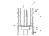
- FIG. 2 is a diagram illustrating a configuration of the casting apparatus 10.
- the casting apparatus 10 includes a chamber (not shown) such as a vacuum chamber and a melting crucible (not shown) for melting the Ni alloy raw material.
- the casting apparatus 10 is provided with a heating zone 14 for heating the mold 12 and a cooling zone 16 for cooling the mold 12.
- the heating zone 14 includes a heater 18 and a susceptor 20.
- the cooling zone 16 includes a water-cooled chill ring 22, a water-cooled chill plate 24, and an elevating body 26.
- the water-cooled chill plate 24 is attached to the elevating body 26 and is configured to be able to move the mold 12 placed on the water-cooled chill plate 24 to the heating zone 14 and the cooling zone 16.
- a heat shielding plate 28 for heat shielding is provided.
- the general casting apparatus used when performing unidirectional solidification casting of metal materials, such as Ni alloy can be used.
- FIG. 3 is a diagram showing the configuration of the mold 12.
- the mold 12 includes a cavity 12a into which molten Ni alloy is poured.
- the mold 12 has a crystal grain refinement layer 12b provided on the cavity 12a side and a backup layer 12c provided outside the crystal grain refinement layer 12b.
- the crystal grain refinement layer 12b is formed of a mixture of a crystal grain refiner made of a cobalt compound and a refractory material, and has a function of miniaturizing crystal grains.
- a crystal grain refining agent made of a cobalt compound functions as a nucleation substance that generates a large number of crystal nuclei when in contact with molten Ni alloy. Since the crystal grain refinement layer 12b provided on the cavity 12a side of the mold 12 contains a crystal grain refiner made of a cobalt compound, many crystal nuclei are generated at the initial stage of solidification of the Ni alloy melt. The grain can be refined.
- cobalt compounds such as cobalt aluminate, cobalt oxide, cobalt acetate, cobalt sulfate, cobalt chloride, cobalt sulfonate, ammonium cobalt sulfate, cobalt thiocyanate, and cobalt nitrate can be used.
- cobalt compounds such as cobalt aluminate, cobalt oxide, cobalt acetate, cobalt sulfate, cobalt chloride, cobalt sulfonate, ammonium cobalt sulfate, cobalt thiocyanate, and cobalt nitrate can be used.
- cobalt compounds such as cobalt aluminate, cobalt oxide, cobalt acetate, cobalt sulfate, cobalt chloride, cobalt sulfonate, ammonium cobalt sulfate, cobalt thiocyanate, and cobalt nit
- ceramics such as alumina, zircon (zirconium silicate), zirconia, and yttria can be used.
- the backup layer 12c is formed of a refractory material and has a function of maintaining the mold strength.
- a refractory material ceramics such as alumina, zircon (zirconium silicate), silica, and mullite having high mechanical strength can be used.
- a general lost wax method or the like can be used as a method for manufacturing the mold 12.
- a slurry containing a grain refiner made of a cobalt compound is applied to a wax model such as a turbine blade, and then a slurry for a backup layer is applied. It may be fired after drying and dewaxing.
- the casting step (S10) is a step in which molten Ni alloy is poured into the cavity 12a of the mold 12 and cast.
- FIG. 4 is a diagram for explaining the casting step (S10).
- the chamber is evacuated to create a vacuum atmosphere.
- the degree of vacuum is, for example, 0.013 Pa (1 ⁇ 10 ⁇ 4 Torr) to 0.13 Pa (1 ⁇ 10 ⁇ 3 Torr).
- an inert gas atmosphere may be formed by introducing an inert gas such as an argon gas into the chamber after the chamber is evacuated.
- the melting crucible is tilted, and the molten Ni alloy 30 is poured into the cavity 12 a of the mold 12.
- the casting temperature is preferably + 100 ° C. or higher and + 150 ° C. or lower with respect to the liquidus of the Ni alloy. This is because if the casting temperature is lower than + 100 ° C. with respect to the liquidus of the Ni alloy, casting defects are likely to occur due to poor hot water. This is because when the casting temperature is higher than + 150 ° C. with respect to the Ni alloy liquidus, the crystal grains are likely to be coarsened.
- Rene 77 which is a Ni-based superalloy
- the liquidus temperature is about 1380 ° C., and therefore, the casting temperature is preferably 1480 ° C. or higher and 1530 ° C. or lower.
- Rene77 As reported in, for example, U.S. Pat. No. 4,478,638, 14.2% by mass to 15.8% by mass Co (cobalt) and 14.0% by mass to 15.3% by mass Cr (chromium), 4.0 mass% to 4.6 mass% Al (aluminum), 3.0 mass% to 3.7 mass% Ti (titanium), 3.9 mass% to 4. 5 wt% Mo (molybdenum), 0.05 wt% to 0.09 wt% C (carbon), 0.012 wt% to 0.02 wt% B (boron), 0.5 wt% % Of Fe (iron) and 0.2 mass% or less of Si (silicon), with the balance being made up of Ni (nickel) and inevitable impurities.
- the mold temperature is preferably + 20 ° C. or higher and + 50 ° C. or lower with respect to the liquid phase line of the Ni alloy.
- the mold temperature is lower than + 20 ° C. with respect to the Ni alloy liquidus, solidification starts from the crystal grain refinement layer 12 b of the mold 12, and the Ni alloy molten metal 30 is integrated from the upper surface of the water-cooled chill plate 24. This is because it may not solidify in the direction.
- the mold temperature is higher than + 50 ° C. with respect to the liquidus of the Ni alloy, the crystal grain refining agent made of a cobalt compound contained in the crystal grain refined layer 12b is dissolved in the Ni alloy melt 30. This is because the crystal grain refinement effect may be reduced.
- Rene 77 which is a Ni-based superalloy
- the liquidus temperature is about 1380 ° C.
- the mold temperature is preferably 1400 ° C. or higher and 1430 ° C. or lower.
- FIG. 5 is a diagram for explaining the columnar crystal forming step (S12).
- the water-cooled chill plate 24 is lowered, and the mold 12 poured with the molten Ni alloy 30 is added at a drawing speed of 100 mm / hour or more and 400 mm / hour or less by providing a temperature gradient at the solid-liquid interface (position of the heat shield plate 28).
- a drawing speed 100 mm / hour or more and 400 mm / hour or less.
- the reason why the drawing speed is 400 mm / hour or less is that when it is larger than 400 mm / hour, the coagulation speed becomes high, so that equiaxed crystals may be formed.
- the drawing speed is preferably 150 mm / hour or more and 250 mm / hour or less.
- the temperature gradient of the solid-liquid interface (solidification interface) to 80 ° C./cm or more in order to suppress the generation of crystal nuclei by the crystal grain refinement layer 12b of the template 12.
- the drawing speed is 100 mm / hour or more and 400 mm / hour or less
- the temperature gradient at the solid-liquid interface is smaller than 80 ° C./cm, it is difficult to suppress the generation of crystal nuclei by the crystal grain refinement layer 12b. This is because equiaxed crystals may be formed.
- the position of the bottom surface of the mold 12 is previously set by a predetermined amount from the reference position (the position of the heat shielding plate 28) to the cooling zone 16 side.
- the mold 12 may be positioned by moving it. Thereby, the temperature gradient of the solid-liquid interface can be made larger than when unidirectional solidification is started using the position of the bottom surface of the mold 12 as the reference position (position of the heat shielding plate 28).
- the amount of movement of the mold 12 toward the cooling zone 16 differs depending on the temperature gradient of the solid-liquid interface, but when the temperature gradient of the solid-liquid interface is 80 ° C./cm or more, it may be 20 mm to 30 mm. .
- the position adjustment of the mold 12 can be adjusted by lowering the water-cooled chill plate 24.
- the length of columnar crystals can be controlled by the drawing time. For example, when the length of the columnar crystal is 200 mm and the drawing is performed at a drawing speed of 200 mm / hour, the drawing time may be set to 1 hour.
- the equiaxed crystal forming step (S14) is a step of forming equiaxed crystals by continuously drawing and solidifying at a drawing speed of 1000 mm / min or more after the columnar crystal forming step (S12).
- FIG. 6 is a diagram for explaining the equiaxed crystal formation step (S14).
- the columnar crystals are continuously formed after the columnar crystal forming step (S12) and solidified by drawing at a drawing speed of 1000 mm / min or more to form equiaxed crystals.
- the drawing speed is 1000 mm / min or more because if the drawing speed is less than 1000 mm / min, the coagulation speed becomes small and it is difficult to form equiaxed crystals. Since the crystal grain refinement layer 12b is provided in the mold 12, it is possible to form equiaxed crystals with crystal grains refined.
- FIG. 7 is a diagram showing a configuration of another mold 40.
- a region where columnar crystals are formed is provided with a refractory material layer 40b made of a refractory material such as alumina and not containing a crystal grain refining agent made of a cobalt compound.
- a crystal grain refinement layer 40c formed with a crystal grain refiner containing a cobalt compound is provided in the region where the equiaxed crystal on the cavity 40a side is formed.
- a backup layer 40d is provided outside the crystal grain refinement layer 40c.
- the mold 40 has the crystal grain refinement layer 40 c containing the crystal grain refiner made of the cobalt compound in the region where the equiaxed crystal is formed on the cavity 40 a side of the mold 40. Since the grain refinement layer 40c is not provided in the region where the columnar crystals are formed on the 40a side, it is not necessary to increase the temperature gradient at the solid-liquid interface in order to suppress the generation of crystal nuclei during columnar crystal formation. There is no need to perform mold positioning work or the like.
- a general lost wax method or the like can be used as a method for manufacturing the mold 40.
- a slurry such as alumina that does not contain a crystal grain refining agent made of a cobalt compound only in a region where a columnar crystal of a wax model such as a turbine blade is formed.
- a slurry containing a crystal grain refining agent made of a cobalt compound is applied to a region where the equiaxed crystal of the wax model is formed, and then a slurry for a backup layer is applied, dried, and dewaxed. It may be fired later.
- Ni alloy for casting Ni alloy castings it is not specifically limited,
- Ni base superalloys such as an Inconel alloy used for a turbine blade etc.
- the Ni alloy casting is not particularly limited, but is preferably a turbine blade.
- FIG. 8 is a schematic diagram showing the configuration of the turbine blade 42.
- the casting process in which the molten Ni alloy is poured into the mold cavity and the mold in which the molten Ni alloy is poured is provided with a temperature gradient at the solid-liquid interface, and the drawing speed is 100 mm / hour.
- a columnar crystal forming step for forming columnar crystals By pulling and solidifying at 400 mm / hour or less, a columnar crystal forming step for forming columnar crystals, and after the columnar crystal forming step, by drawing and solidifying at a drawing speed of 1000 mm / min or more continuously, equiaxed crystals are formed. Since the equiaxed crystal forming step is formed, the columnar crystals and the equiaxed crystals are formed continuously, so that it is not necessary to perform casting a plurality of times. Thereby, casting work is reduced and the productivity of Ni alloy castings can be improved.
- the mold has the crystal grain refinement layer containing the crystal grain refiner made of the cobalt compound on the cavity side of the mold, and the columnar crystal formation step is performed from the crystal grain refinement layer.
- the temperature gradient at the solid-liquid interface is set to 80 ° C./cm or more. Therefore, the generation of crystal nuclei from the crystal grain refinement layer of the template is suppressed during columnar crystal formation. Further, when forming equiaxed crystals, crystal nuclei are generated from the crystal grain refinement layer of the template, so that fine equiaxed crystal grains can be formed.
- the grain refinement layer is provided in the region where the columnar crystals on the cavity side of the mold are formed, the columnar crystals and the fine equiaxed crystals can be cast continuously.
- the productivity of Ni alloy castings can be improved.
- the mold can be easily manufactured and the productivity of the Ni alloy cast product is improved.
- a vibration device or the like for refining the crystal grains is unnecessary, the production cost of the Ni alloy casting can be reduced.
- the template is provided with the crystal grain refinement layer including the crystal grain refiner made of the cobalt compound only in the region where the equiaxed crystal is formed on the cavity side of the mold, columnar crystal formation is performed. Sometimes the generation of crystal nuclei is suppressed. At the time of equiaxed crystal formation, crystal nuclei are generated from the crystal grain refined layer, and fine equiaxed crystals can be formed. Thereby, since columnar crystals and fine equiaxed crystals can be cast continuously, the productivity of Ni alloy castings can be improved. In addition, when forming columnar crystals, it is not necessary to increase the temperature gradient at the solid-liquid interface in order to suppress the generation of crystal nuclei, and it is not necessary to adjust the position of the mold to increase the temperature gradient. Product productivity is improved.
- Ni alloy casting For the Ni alloy casting, a rectangular sheet was cast. For the Ni alloy, Rene77, which is a Ni-based superalloy, was used. About the casting apparatus, the thing similar to the structure of the casting apparatus 10 shown in FIG. 2 was used. As the template, a template having the same structure as the template 12 shown in FIG. 3 was used. Cobalt aluminate was used for the cobalt compound contained in the grain refinement layer. The backup layer was made of alumina.
- the water-cooled chill plate was lowered and the mold was positioned at a position withdrawn 20 mm toward the cooling zone in order to increase the temperature gradient at the solid-liquid interface during columnar crystal formation.
- a molten Ni alloy was poured into the cavity of the mold.
- the casting temperature was 1530 ° C.
- the mold temperature was 1430 ° C.
- the temperature of the water-cooled chill plate was 300 ° C.
- the degree of vacuum was set to 0.013 Pa (1 ⁇ 10 ⁇ 4 Torr).
- the casting mold filled with Ni alloy melt is drawn from the heating zone to the cooling zone with a temperature gradient at the solid-liquid interface and solidified by drawing from the heating zone to 250 mm / hour. Columnar crystals were formed.
- the temperature gradient at the solid-liquid interface was set to 80 ° C./cm to 100 ° C./cm.
- a columnar crystal was formed by lowering the water-cooled chill plate, and then an equiaxed crystal was formed by drawing from the heating zone to the cooling zone at a drawing speed of 1000 mm / min and solidifying.
- FIG. 9 is a photograph showing the appearance observation result of the Ni alloy casting.
- columnar crystals were formed on the lower side of the Ni alloy casting, and fine equiaxed crystals were formed on the upper side of the Ni alloy casting.
- fine equiaxed crystals were formed continuously with the columnar crystals.
- no equiaxed crystal was observed in the region where columnar crystals were formed. From this, it was found that the generation of crystal nuclei due to the grain refinement layer can be suppressed by increasing the temperature gradient at the solid-liquid interface during columnar crystal formation.
- FIG. 10 is a photograph showing the microstructure observation result of the Ni alloy casting
- FIG. 10 (a) is a photograph showing the microstructure observation result of the columnar crystal region
- FIG. 10 (b) is equiaxed. It is a photograph which shows the microstructure observation result of the area
- the metal structure perpendicular to the drawing direction of the Ni alloy casting was observed.
- the crystal grain sizes of columnar crystals and equiaxed crystals were obtained by measuring the crystal grain sizes of a plurality of crystal grains in a metal structure perpendicular to the drawing direction of the Ni alloy casting, and averaging these. .
- the crystal grain size of the columnar crystals was 0.45 mm to 0.55 mm
- the crystal grain size of the equiaxed crystals was 1 mm to 4 mm.
- the present disclosure is useful for production of Ni alloy castings such as turbine blades because the equiaxed crystals are continuously formed after the columnar crystals are formed by continuously changing the drawing speed after casting. .
Landscapes
- Engineering & Computer Science (AREA)
- Mechanical Engineering (AREA)
- Chemical & Material Sciences (AREA)
- Materials Engineering (AREA)
- Metallurgy (AREA)
- Organic Chemistry (AREA)
- General Engineering & Computer Science (AREA)
- Turbine Rotor Nozzle Sealing (AREA)
- Structures Of Non-Positive Displacement Pumps (AREA)
Abstract
Ni合金鋳造品の製造方法は、Ni合金溶湯を鋳型のキャビティに注湯して鋳込む鋳込み工程(S10)と、Ni合金溶湯を注湯した鋳型を、固液界面に温度勾配を設けて引抜速度100mm/時間以上400mm/時間以下で引き抜いて凝固させることにより、柱状晶を形成する柱状晶形成工程(S12)と、柱状晶形成工程の後に連続して引抜速度1000mm/分以上で引き抜いて凝固させることにより等軸晶を形成する等軸晶形成工程(S14)と、を備える。
Description
本開示は、Ni合金鋳造品の製造方法及びNi合金鋳造品に関する。
Ni合金鋳造品、例えば、Ni合金で鋳造されたタービンブレードでは、翼部にはクリープ強度が要求され、ダブテール部には疲労強度が要求される。このため、タービンブレードの翼部を柱状晶組織とし、ダブテール部を等軸晶組織とすることにより、強度特性に優れたタービンブレードを鋳造することができる。
特許文献1には、翼部が柱状晶組織であり、ダブテール部が等軸晶組織であるNi基合金製のタービン用動翼の製造方法において、1回目の鋳込みで翼部の体積と等しい量の合金を鋳込み、一方向凝固させて柱状晶組織を形成した後に、追加チャージして2回目の鋳込みを行うことにより等軸晶組織を形成することが記載されている。
ところで、特許文献1に記載されているように、複数回の鋳込みを行って柱状晶組織と等軸晶組織とからなるNi合金鋳造品を製造する場合には、鋳込み回数の増加や鋳込み作業の煩雑等により、Ni合金鋳造品の生産性が低下する可能性がある。
そこで本開示の目的は、Ni合金鋳造品の生産性を向上させることが可能なNi合金鋳造品の製造方法及びNi合金鋳造品を提供することである。
本発明の実施形態に係るNi合金鋳造品の製造方法は、Ni合金溶湯を鋳型のキャビティに注湯して鋳込む鋳込み工程と、前記Ni合金溶湯を注湯した鋳型を、固液界面に温度勾配を設けて引抜速度100mm/時間以上400mm/時間以下で引き抜いて凝固させることにより、柱状晶を形成する柱状晶形成工程と、前記柱状晶形成工程の後に連続して引抜速度1000mm/分以上で引き抜いて凝固させることにより等軸晶を形成する等軸晶形成工程と、を備える。
本発明の実施形態に係るNi合金鋳造品の製造方法において、前記鋳型は、前記鋳型のキャビティ側に、コバルト化合物からなる結晶粒微細化剤を含む結晶粒微細化層を有しており、前記柱状晶形成工程は、固液界面の温度勾配を80℃/cm以上にする。
本発明の実施形態に係るNi合金鋳造品の製造方法において、前記鋳型は、前記鋳型のキャビティ側における等軸晶を形成する領域にコバルト化合物からなる結晶粒微細化剤を含む結晶粒微細化層を有しており、前記鋳型のキャビティ側における柱状晶を形成する領域に前記結晶粒微細化層を有していない。
本発明の実施形態に係るNi合金鋳造品の製造方法において、前記結晶粒微細化剤は、アルミン酸コバルト、酸化コバルト、酢酸コバルト、硫酸コバルト、塩化コバルト、スルフォン酸コバルト、硫酸アンモニウムコバルト、チオシアン酸コバルトまたは硝酸コバルトである。
本発明の実施形態に係るNi合金鋳造品の製造方法において、前記Ni合金鋳造品は、タービンブレードであり、前記タービンブレードの翼部が柱状晶で形成され、前記タービンブレードのダブテール部が等軸晶で形成される。
本発明の実施形態に係るNi合金鋳造品は、上記のいずれか1つに記載のNi合金鋳造品の製造方法で製造されたNi合金鋳造品における引抜方向に対して直交方向の柱状晶の結晶粒径が、0.45mmから0.55mmである。
上記構成によれば、鋳込み後の引抜速度を連続して変えることにより、柱状晶を形成した後に連続して等軸晶を形成するので、Ni合金鋳造品の生産性を向上させることができる。
以下に本発明の実施の形態について図面を用いて詳細に説明する。図1は、Ni合金鋳造品の製造方法の構成を示すフローチャートである。Ni合金鋳造品の製造方法は、鋳込み工程(S10)と、柱状晶形成工程(S12)と、等軸晶形成工程(S14)と、を備えている。
まず、Ni合金鋳造品を鋳造するための鋳造装置について説明する。図2は、鋳造装置10の構成を示す図である。
鋳造装置10は、真空チャンバ等のチャンバ(図示せず)と、Ni合金原料を溶解するための溶解坩堝(図示せず)と、を備えている。鋳造装置10には、鋳型12を加熱するための加熱帯14と、鋳型12を冷却するための冷却帯16とが設けられている。加熱帯14は、ヒータ18と、サセプタ20とを含んで構成されている。冷却帯16は、水冷チルリング22と、水冷チルプレート24と、昇降体26とを含んで構成されている。水冷チルプレート24は、昇降体26に取り付けられており、水冷チルプレート24に載置された鋳型12を加熱帯14や冷却帯16に移動可能に構成されている。加熱帯14と冷却帯16との間には、熱遮蔽するための熱遮蔽板28が設けられている。鋳造装置10については、Ni合金等の金属材料の一方向凝固鋳造を行うときに用いられる一般的な鋳造装置を用いることができる。
次に、鋳型12について説明する。図3は、鋳型12の構成を示す図である。鋳型12は、Ni合金溶湯が注湯されるキャビティ12aを備えている。鋳型12は、キャビティ12a側に設けられた結晶粒微細化層12bと、結晶粒微細化層12bの外側に設けられたバックアップ層12cと、を有している。
結晶粒微細化層12bは、コバルト化合物からなる結晶粒微細化剤と、耐火材との混合物により形成されており、結晶粒を微細化する機能を有している。コバルト化合物からなる結晶粒微細化剤は、Ni合金溶湯と接触することにより、多くの結晶核を発生させる核発生物質として機能する。鋳型12のキャビティ12a側に設けられた結晶粒微細化層12bがコバルト化合物からなる結晶粒微細化剤を含むことにより、Ni合金溶湯の凝固の初期段階に多くの結晶核が発生するので、結晶粒を微細化することができる。
結晶粒微細化剤については、アルミン酸コバルト、酸化コバルト、酢酸コバルト、硫酸コバルト、塩化コバルト、スルフォン酸コバルト、硫酸アンモニウムコバルト、チオシアン酸コバルト、硝酸コバルト等のコバルト化合物を用いることが可能である。これらのコバルト化合物については、一般的な市販品を用いることができる。
耐火材については、アルミナ、ジルコン(珪酸ジルコニウム)、ジルコニア、イットリア等のセラミックスを用いることが可能である。
バックアップ層12cは、耐火材で形成されており、鋳型強度を保持する機能を有している。耐火材には、機械的強度が大きいアルミナ、ジルコン(珪酸ジルコニウム)、シリカ、ムライト等のセラミックスを用いることができる。
鋳型12の製造方法については、一般的なロストワックス法等を用いることが可能である。鋳型12をロストワックス法で製造する場合には、例えば、タービンブレード等の蝋型模型に、コバルト化合物からなる結晶粒微細化剤を含むスラリを塗布した後に、バックアップ層用のスラリを塗布して乾燥し、脱蝋した後に焼成すればよい。
鋳込み工程(S10)は、Ni合金溶湯を鋳型12のキャビティ12aに注湯して鋳込む工程である。図4は、鋳込み工程(S10)を説明するための図である。
まず、チャンバ内を排気して、チャンバ内を真空雰囲気にする。真空度については、例えば、0.013Pa(1×10⁻⁴Torr)から0.13Pa(1×10⁻³Torr)である。なお、チャンバ内を排気した後に、チャンバ内にアルゴンガス等の不活性ガスを導入して不活性ガス雰囲気としてもよい。次に、溶解坩堝を傾動させて、鋳型12のキャビティ12aにNi合金溶湯30を注湯する。
鋳込み温度については、Ni合金の液相線に対して+100℃以上+150℃以下であることが好ましい。鋳込み温度がNi合金の液相線に対して+100℃より低温である場合には、湯廻り不良等により鋳造欠陥が生じ易いからである。鋳込み温度がNi合金の液相線に対して+150℃より高温である場合には、結晶粒が粗大化し易いからである。例えば、Ni合金にNi基超合金であるRene77を用いた場合には、液相線温度が約1380℃であるので、鋳込み温度については、1480℃以上1530℃以下とすることが好ましい。なお、Rene77については、例えば米国特許第4478638号に報告されているように、14.2質量%から15.8質量%のCo(コバルト)と、14.0質量%から15.3質量%のCr(クロム)と、4.0質量%から4.6質量%のAl(アルミニウム)と、3.0質量%から3.7質量%のTi(チタン)と、3.9質量%から4.5質量%のMo(モリブデン)と、0.05質量%から0.09質量%のC(炭素)と、0.012質量%から0.02質量%のB(ホウ素)と、0.5質量%以下のFe(鉄)と、0.2質量%以下のSi(珪素)と、を含み、残部がNi(ニッケル)と不可避的不純物とから構成されている。
鋳型温度については、Ni合金の液相線に対して+20℃以上+50℃以下であることが好ましい。鋳型温度がNi合金の液相線に対して+20℃より低温である場合には、鋳型12の結晶粒微細化層12bからも凝固が始まり、水冷チルプレート24の上面からNi合金溶湯30が一方向に凝固しない可能性があるからである。鋳型温度がNi合金の液相線に対して+50℃より高温である場合には、結晶粒微細化層12bに含まれるコバルト化合物からなる結晶粒微細化剤がNi合金溶湯30に溶け込むことで、結晶粒の微細化効果が低減する可能性があるからである。例えば、Ni合金にNi基超合金であるRene77を用いた場合には、液相線温度が約1380℃であるので、鋳型温度については、1400℃以上1430℃以下とすることが好ましい。
柱状晶形成工程(S12)は、Ni合金溶湯30を注湯した鋳型12を、固液界面(凝固界面)に温度勾配を設けて引抜速度100mm/時間以上400mm/時間以下で引き抜いて凝固させることにより、柱状晶を形成する工程である。図5は、柱状晶形成工程(S12)を説明するための図である。
水冷チルプレート24を下降させて、Ni合金溶湯30を注湯した鋳型12を、固液界面(熱遮蔽板28の位置)に温度勾配を設けて引抜速度100mm/時間以上400mm/時間以下で加熱帯14から冷却帯16へ引き抜いて凝固させることにより、水冷チルプレート24の上面から鋳型12の上方に向けて一方向に冷却されて凝固し、結晶粒が一方向に成長して柱状晶が形成される。引抜速度が100mm/時間以上であるのは、100mm/時間より小さい場合には、凝固速度が小さくなるのでNi合金鋳造品の生産性が低下するからである。引抜速度が400mm/時間以下であるのは、400mm/時間より大きい場合には、凝固速度が大きくなるので等軸晶が形成される可能性があるからである。引抜速度については、150mm/時間以上250mm/時間以下であることが好ましい。
柱状晶形成時には、鋳型12の結晶粒微細化層12bによる結晶核の発生を抑制するために、固液界面(凝固界面)の温度勾配を80℃/cm以上とすることが好ましい。引抜速度が100mm/時間以上400mm/時間以下の場合において、固液界面の温度勾配が80℃/cmより小さい場合には、結晶粒微細化層12bによる結晶核の発生を抑制し難くなるので、等軸晶が形成される可能性があるからである。固液界面の温度勾配と、引抜速度と、金属組織との関係においては、固液界面の温度勾配がより大きく、引抜速度がより小さい(凝固速度が小さい)ほど柱状晶が形成されやすく、固液界面の温度勾配がより小さく、引抜速度がより大きい(凝固速度が大きい)ほど等軸晶が形成されやすい。このため、引抜速度が100mm/時間以上400mm/時間以下の場合において、固液界面の温度勾配を80℃/cm以上とすることにより、一般的な一方向凝固を行う場合の固液界面の温度勾配より大きくすることで、結晶粒微細化層12bによる結晶核の発生を抑制することが可能となる。
固液界面の温度勾配を大きくするためには、例えば、鋳込み工程(S10)において、予め、鋳型12の底面の位置を基準位置(熱遮蔽板28の位置)から冷却帯16側へ所定量だけ移動させて、鋳型12を位置決めしておけばよい。これにより、鋳型12の底面の位置を基準位置(熱遮蔽板28の位置)として一方向凝固を開始する場合よりも、固液界面の温度勾配を大きくすることができる。鋳型12の冷却帯16側への移動量については、固液界面の温度勾配により相違するが、固液界面の温度勾配を80℃/cm以上とする場合には、20mmから30mmとすればよい。鋳型12の位置調整については、水冷チルプレート24を下降させることにより調整可能である。
柱状晶の長さについては、引抜時間で制御することが可能である。例えば、柱状晶の長さを200mmとする場合において、引抜速度200mm/時間で引き抜く場合には、引抜時間を1時間とすればよい。
等軸晶形成工程(S14)は、柱状晶形成工程(S12)の後に連続して引抜速度1000mm/分以上で引き抜いて凝固させることにより等軸晶を形成する工程である。図6は、等軸晶形成工程(S14)を説明するための図である。
水冷チルプレート24を下降させることにより、柱状晶形成工程(S12)の後に連続して引抜速度1000mm/分以上で引き抜いて凝固させることにより、柱状晶32に連続して等軸晶を形成することができる。引抜速度が1000mm/分以上であるのは、引抜速度が1000mm/分より小さいと凝固速度が小さくなるので等軸晶を形成し難くなるからである。鋳型12には結晶粒微細化層12bが設けられているので、結晶粒が微細化した等軸晶を形成することが可能となる。
また、上記構成の鋳型12に代えて、他の鋳型を用いることが可能である。図7は、他の鋳型40の構成を示す図である。鋳型40では、鋳型40のキャビティ40a側において、柱状晶が形成される領域には、コバルト化合物からなる結晶粒微細化剤を含まず、アルミナ等の耐火材で形成された耐火材層40bが設けられており、キャビティ40a側の等軸晶が形成される領域には、コバルト化合物を含む結晶粒微細化剤で形成された結晶粒微細化層40cが設けられている。また、結晶粒微細化層40cの外側には、バックアップ層40dが設けられている。このように、鋳型40は、鋳型40のキャビティ40a側における等軸晶を形成する領域にコバルト化合物からなる結晶粒微細化剤を含む結晶粒微細化層40cを有しており、鋳型40のキャビティ40a側における柱状晶を形成する領域に結晶粒微細化層40cを有していないことにより、柱状晶形成時に結晶核の発生を抑制するために固液界面の温度勾配を大きくする必要がないので、鋳型の位置決め作業等を行う必要がない。
鋳型40の製造方法については、一般的なロストワックス法等を用いることが可能である。鋳型40をロストワックス法で製造する場合には、例えば、タービンブレード等の蝋型模型の柱状晶を形成する領域のみに、コバルト化合物からなる結晶粒微細化剤が含まれていないアルミナ等のスラリを塗布した後に、蝋型模型の等軸晶を形成する領域にコバルト化合物からなる結晶粒微細化剤を含むスラリを塗布し、次にバックアップ層用のスラリを塗布して乾燥し、脱蝋した後に焼成すればよい。
なお、Ni合金鋳造品を鋳造するためのNi合金については、特に限定されることなく、例えば、タービンブレード等に用いられるインコネル合金等のNi基超合金を用いることができる。Ni合金鋳造品については、特に限定されないが、タービンブレードであることが好ましい。図8は、タービンブレード42の構成を示す模式図である。タービンブレード42の翼部44を柱状晶で形成し、ダブテール部46を等軸晶で形成することにより、翼部44ではクリープ強度が向上し、ダブテール部46では疲労強度が向上した優れた強度特性を有するタービンブレード42を製造できる。
以上、上記構成によれば、Ni合金溶湯を鋳型のキャビティに注湯して鋳込む鋳込み工程と、Ni合金溶湯を注湯した鋳型を、固液界面に温度勾配を設けて引抜速度100mm/時間以上400mm/時間以下で引き抜いて凝固させることにより、柱状晶を形成する柱状晶形成工程と、柱状晶形成工程の後に連続して引抜速度1000mm/分以上で引き抜いて凝固させることにより等軸晶を形成する等軸晶形成工程と、を備えていることから、柱状晶と等軸晶とが連続して形成されるので、複数回の鋳込みを行う必要がない。これにより鋳込み作業が軽減されてNi合金鋳造品の生産性を向上させることができる。
上記構成によれば、鋳型は、鋳型のキャビティ側に、コバルト化合物からなる結晶粒微細化剤を含む結晶粒微細化層を有しており、柱状晶形成工程は、結晶粒微細化層からの結晶核の発生を抑制するために、固液界面の温度勾配を80℃/cm以上にしているので、柱状晶形成時には、鋳型の結晶粒微細化層からの結晶核の発生が抑制される。また、等軸晶形成時には、鋳型の結晶粒微細化層から結晶核が発生するので微細な等軸晶の結晶粒を形成することができる。このように、鋳型のキャビティ側の柱状晶が形成される領域に結晶粒微細化層が設けられている場合でも、柱状晶と、微細な等軸晶とを連続して鋳造可能であることから、Ni合金鋳造品の生産性を向上させることができる。また、鋳型のキャビティ側の柱状晶が形成される領域に結晶粒微細化層が設けられている場合でも鋳造可能であることから鋳型製造が容易となり、Ni合金鋳造品の生産性が向上する。更に、結晶粒を微細化するための振動装置等が不要であることから、Ni合金鋳造品の生産コストを低減することができる。
上記構成によれば、鋳型は、鋳型のキャビティ側における等軸晶を形成する領域にのみ、コバルト化合物からなる結晶粒微細化剤を含む結晶粒微細化層が設けられているので、柱状晶形成時には結晶核の発生が抑制される。等軸晶形成時では、結晶粒微細化層から結晶核が発生し、微細な等軸晶を形成することができる。これにより、柱状晶と、微細な等軸晶とを連続して鋳造可能であることから、Ni合金鋳造品の生産性を向上させることができる。また、柱状晶形成時には、結晶核の発生を抑制するために固液界面の温度勾配を大きくする必要がなく、温度勾配を大きくするための鋳型の位置調整作業が不要になるので、Ni合金鋳造品の生産性が向上する。
Ni合金鋳造品について鋳造試験を行った。
(鋳造方法)
Ni合金鋳造品については、矩形状シートを鋳造した。Ni合金については、Ni基超合金であるRene77を用いた。鋳造装置については、図2に示す鋳造装置10の構成と同様のものを使用した。鋳型については、図3に示す鋳型12と同様の構成の鋳型を用いた。結晶粒微細化層に含まれるコバルト化合物については、アルミン酸コバルトを用いた。バックアップ層については、アルミナで形成した。
Ni合金鋳造品については、矩形状シートを鋳造した。Ni合金については、Ni基超合金であるRene77を用いた。鋳造装置については、図2に示す鋳造装置10の構成と同様のものを使用した。鋳型については、図3に示す鋳型12と同様の構成の鋳型を用いた。結晶粒微細化層に含まれるコバルト化合物については、アルミン酸コバルトを用いた。バックアップ層については、アルミナで形成した。
鋳型を水冷チルプレートに載置した後に、水冷チルプレートを下降させて、柱状晶形成時における固液界面の温度勾配を大きくするために、冷却帯側に20mm引き抜いた位置で鋳型を位置決めした。鋳型のキャビティに、Ni合金溶湯を注湯した。鋳込み温度については1530℃とし、鋳型温度については1430℃とした。水冷チルプレートの温度については300℃とした。真空度については、0.013Pa(1×10⁻⁴Torr)とした。
水冷チルプレートを下降させることにより、Ni合金溶湯を注湯した鋳型を、固液界面に温度勾配を設けて引抜速度150mm/時間から250mm/時間で加熱帯から冷却帯へ引き抜いて凝固させることにより、柱状晶を形成した。固液界面の温度勾配については80℃/cmから100℃/cmとした。
水冷チルプレートを下降させることにより、柱状晶を形成した後に連続して、引抜速度1000mm/分で加熱帯から冷却帯へ引き抜いて凝固させることにより、等軸晶を形成した。
(外観観察)
Ni合金鋳造品について外観観察を行った。図9は、Ni合金鋳造品の外観観察結果を示す写真である。図9に示すように、Ni合金鋳造品の下側では柱状晶が形成されており、Ni合金鋳造品の上側では微細な等軸晶が形成された。このように、Ni合金鋳造品では、柱状晶に連続して微細な等軸晶が形成されていた。また、Ni合金鋳造品において、柱状晶が形成されている領域には、等軸晶が認められなかった。このことから、柱状晶形成時に固液界面の温度勾配を大きくすることにより、結晶粒微細化層による結晶核の発生を抑制できることがわかった。
Ni合金鋳造品について外観観察を行った。図9は、Ni合金鋳造品の外観観察結果を示す写真である。図9に示すように、Ni合金鋳造品の下側では柱状晶が形成されており、Ni合金鋳造品の上側では微細な等軸晶が形成された。このように、Ni合金鋳造品では、柱状晶に連続して微細な等軸晶が形成されていた。また、Ni合金鋳造品において、柱状晶が形成されている領域には、等軸晶が認められなかった。このことから、柱状晶形成時に固液界面の温度勾配を大きくすることにより、結晶粒微細化層による結晶核の発生を抑制できることがわかった。
(ミクロ組織観察)
Ni合金鋳造品について光学顕微鏡によりミクロ組織観察を行った。図10は、Ni合金鋳造品のミクロ組織観察結果を示す写真であり、図10(a)は、柱状晶の領域のミクロ組織観察結果を示す写真であり、図10(b)は、等軸晶の領域のミクロ組織観察結果を示す写真である。ミクロ組織観察については、Ni合金鋳造品の引抜方向に対して直交方向の金属組織を観察した。また、柱状晶及び等軸晶の結晶粒径については、Ni合金鋳造品の引抜方向に対して直交方向の金属組織において複数の結晶粒の結晶粒径を測定し、これらを平均して求めた。この結果、柱状晶の結晶粒径については、0.45mmから0.55mmであり、等軸晶の結晶粒径については、1mmから4mmであった。
Ni合金鋳造品について光学顕微鏡によりミクロ組織観察を行った。図10は、Ni合金鋳造品のミクロ組織観察結果を示す写真であり、図10(a)は、柱状晶の領域のミクロ組織観察結果を示す写真であり、図10(b)は、等軸晶の領域のミクロ組織観察結果を示す写真である。ミクロ組織観察については、Ni合金鋳造品の引抜方向に対して直交方向の金属組織を観察した。また、柱状晶及び等軸晶の結晶粒径については、Ni合金鋳造品の引抜方向に対して直交方向の金属組織において複数の結晶粒の結晶粒径を測定し、これらを平均して求めた。この結果、柱状晶の結晶粒径については、0.45mmから0.55mmであり、等軸晶の結晶粒径については、1mmから4mmであった。
本開示は、鋳込み後の引抜速度を連続して変えることにより、柱状晶を形成した後に連続して等軸晶を形成するので、タービンブレード等のNi合金鋳造品の生産に有用なものである。
Claims (10)
- Ni合金鋳造品の製造方法であって、
Ni合金溶湯を鋳型のキャビティに注湯して鋳込む鋳込み工程と、
前記Ni合金溶湯を注湯した鋳型を、固液界面に温度勾配を設けて引抜速度100mm/時間以上400mm/時間以下で引き抜いて凝固させることにより、柱状晶を形成する柱状晶形成工程と、
前記柱状晶形成工程の後に連続して引抜速度1000mm/分以上で引き抜いて凝固させることにより等軸晶を形成する等軸晶形成工程と、
を備える、Ni合金鋳造品の製造方法。 - 請求項1に記載のNi合金鋳造品の製造方法であって、
前記鋳型は、前記鋳型のキャビティ側に、コバルト化合物からなる結晶粒微細化剤を含む結晶粒微細化層を有しており、
前記柱状晶形成工程は、固液界面の温度勾配を80℃/cm以上にする、Ni合金鋳造品の製造方法。 - 請求項1に記載のNi合金鋳造品の製造方法であって、
前記鋳型は、前記鋳型のキャビティ側における等軸晶を形成する領域にコバルト化合物からなる結晶粒微細化剤を含む結晶粒微細化層を有しており、前記鋳型のキャビティ側における柱状晶を形成する領域に前記結晶粒微細化層を有していない、Ni合金鋳造品の製造方法。 - 請求項2または3に記載のNi合金鋳造品の製造方法であって、
前記結晶粒微細化剤は、アルミン酸コバルト、酸化コバルト、酢酸コバルト、硫酸コバルト、塩化コバルト、スルフォン酸コバルト、硫酸アンモニウムコバルト、チオシアン酸コバルトまたは硝酸コバルトである、Ni合金鋳造品の製造方法。 - 請求項1から3のいずれか1つに記載のNi合金鋳造品の製造方法であって、
前記Ni合金鋳造品は、タービンブレードであり、
前記タービンブレードの翼部が柱状晶で形成され、前記タービンブレードのダブテール部が等軸晶で形成される、Ni合金鋳造品の製造方法。 - 請求項4に記載のNi合金鋳造品の製造方法であって、
前記Ni合金鋳造品は、タービンブレードであり、
前記タービンブレードの翼部が柱状晶で形成され、前記タービンブレードのダブテール部が等軸晶で形成される、Ni合金鋳造品の製造方法。 - 請求項1から3のいずれか1つに記載のNi合金鋳造品の製造方法で製造されたNi合金鋳造品における引抜方向に対して直交方向の柱状晶の結晶粒径が、0.45mmから0.55mmである、Ni合金鋳造品。
- 請求項4に記載のNi合金鋳造品の製造方法で製造されたNi合金鋳造品における引抜方向に対して直交方向の柱状晶の結晶粒径が、0.45mmから0.55mmである、Ni合金鋳造品。
- 請求項5に記載のNi合金鋳造品の製造方法で製造されたNi合金鋳造品における引抜方向に対して直交方向の柱状晶の結晶粒径が、0.45mmから0.55mmである、Ni合金鋳造品。
- 請求項6に記載のNi合金鋳造品の製造方法で製造されたNi合金鋳造品における引抜方向に対して直交方向の柱状晶の結晶粒径が、0.45mmから0.55mmである、Ni合金鋳造品。
Priority Applications (3)
| Application Number | Priority Date | Filing Date | Title |
|---|---|---|---|
| CN201680007038.9A CN107206481B (zh) | 2015-02-03 | 2016-01-19 | Ni合金铸造品的制造方法和Ni合金铸造品 |
| EP16746406.4A EP3241632B1 (en) | 2015-02-03 | 2016-01-19 | METHOD OF MANUFACTURING Ni ALLOY CASTING AND Ni ALLOY CASTING |
| US15/661,513 US10421121B2 (en) | 2015-02-03 | 2017-07-27 | Method of manufacturing Ni alloy casting and Ni alloy casting |
Applications Claiming Priority (2)
| Application Number | Priority Date | Filing Date | Title |
|---|---|---|---|
| JP2015019261A JP6682762B2 (ja) | 2015-02-03 | 2015-02-03 | Ni合金鋳造品の製造方法 |
| JP2015-019261 | 2015-02-03 |
Related Child Applications (1)
| Application Number | Title | Priority Date | Filing Date |
|---|---|---|---|
| US15/661,513 Continuation US10421121B2 (en) | 2015-02-03 | 2017-07-27 | Method of manufacturing Ni alloy casting and Ni alloy casting |
Publications (1)
| Publication Number | Publication Date |
|---|---|
| WO2016125575A1 true WO2016125575A1 (ja) | 2016-08-11 |
Family
ID=56563926
Family Applications (1)
| Application Number | Title | Priority Date | Filing Date |
|---|---|---|---|
| PCT/JP2016/051361 Ceased WO2016125575A1 (ja) | 2015-02-03 | 2016-01-19 | Ni合金鋳造品の製造方法及びNi合金鋳造品 |
Country Status (5)
| Country | Link |
|---|---|
| US (1) | US10421121B2 (ja) |
| EP (1) | EP3241632B1 (ja) |
| JP (1) | JP6682762B2 (ja) |
| CN (1) | CN107206481B (ja) |
| WO (1) | WO2016125575A1 (ja) |
Cited By (1)
| Publication number | Priority date | Publication date | Assignee | Title |
|---|---|---|---|---|
| WO2019002797A1 (fr) * | 2017-06-29 | 2019-01-03 | Safran Aircraft Engines | Procede de fonderie avec coulee en moule chaud |
Families Citing this family (4)
| Publication number | Priority date | Publication date | Assignee | Title |
|---|---|---|---|---|
| CA3068408C (en) * | 2017-06-30 | 2023-01-17 | Siemens Aktiengesellschaft | An additive manufacturing technique for precipitation-hardened superalloy powdered material |
| WO2020203868A1 (ja) * | 2019-04-01 | 2020-10-08 | 株式会社Ihi | タービンホイール及びその製造方法 |
| JP7259659B2 (ja) * | 2019-09-06 | 2023-04-18 | 株式会社Ihi | タービンブレード及びタービンブレードの製造方法 |
| CN114289691A (zh) * | 2021-12-16 | 2022-04-08 | 江苏隆达超合金航材有限公司 | 一种合金锭浇注用复合模管 |
Citations (4)
| Publication number | Priority date | Publication date | Assignee | Title |
|---|---|---|---|---|
| JPS5150814A (ja) * | 1974-10-31 | 1976-05-04 | Mitsubishi Heavy Ind Ltd | Ichihokogyokoimonono seisakuhoho |
| JPS57184572A (en) * | 1981-05-11 | 1982-11-13 | Hitachi Ltd | Production of unidirectionally solidified casting |
| JPH03134201A (ja) * | 1989-10-18 | 1991-06-07 | Hitachi Ltd | ガスタービン用動翼及びその製造方法 |
| JPH05200529A (ja) * | 1991-08-29 | 1993-08-10 | General Electric Co <Ge> | アルミニウム化チタンの方向性凝固鋳造法 |
Family Cites Families (12)
| Publication number | Priority date | Publication date | Assignee | Title |
|---|---|---|---|---|
| US4637448A (en) * | 1984-08-27 | 1987-01-20 | Westinghouse Electric Corp. | Method for production of combustion turbine blade having a single crystal portion |
| US4905752A (en) * | 1988-03-28 | 1990-03-06 | Pcc Airfoils, Inc. | Method of casting a metal article |
| KR920008321A (ko) * | 1990-10-31 | 1992-05-27 | 아더 엠. 킹 | 산업용 가스터어빈 엔진 버킷 및 그 제조 방법 |
| DE69423061T2 (de) * | 1993-08-06 | 2000-10-12 | Hitachi, Ltd. | Gasturbinenschaufel, Verfahren zur Herstellung derselben sowie Gasturbine mit dieser Schaufel |
| US5577547A (en) * | 1994-04-28 | 1996-11-26 | Precision Castparts Corp. | Method of casting a metal article |
| JP2002331353A (ja) * | 2001-05-09 | 2002-11-19 | Mitsubishi Materials Corp | 微細な一方向凝固柱状晶組織を有する鋳造体の製造方法 |
| JP2002331352A (ja) * | 2001-05-09 | 2002-11-19 | Mitsubishi Materials Corp | タービンブレードの製造方法 |
| CN100543164C (zh) * | 2007-04-25 | 2009-09-23 | 中国科学院金属研究所 | 一种定向凝固抗热腐蚀镍基铸造高温合金及其制备方法 |
| US20100071812A1 (en) * | 2008-09-25 | 2010-03-25 | General Electric Company | Unidirectionally-solidification process and castings formed thereby |
| US20130160967A1 (en) | 2011-12-23 | 2013-06-27 | General Electric Company | Casting methods for making articles having a fine equiaxed grain structure |
| US10082032B2 (en) | 2012-11-06 | 2018-09-25 | Howmet Corporation | Casting method, apparatus, and product |
| JP6136210B2 (ja) * | 2012-11-21 | 2017-05-31 | 株式会社Ihi | 鋳型及びその製造方法、精密鋳造装置並びに精密鋳造方法 |
-
2015
- 2015-02-03 JP JP2015019261A patent/JP6682762B2/ja active Active
-
2016
- 2016-01-19 EP EP16746406.4A patent/EP3241632B1/en active Active
- 2016-01-19 WO PCT/JP2016/051361 patent/WO2016125575A1/ja not_active Ceased
- 2016-01-19 CN CN201680007038.9A patent/CN107206481B/zh active Active
-
2017
- 2017-07-27 US US15/661,513 patent/US10421121B2/en active Active
Patent Citations (4)
| Publication number | Priority date | Publication date | Assignee | Title |
|---|---|---|---|---|
| JPS5150814A (ja) * | 1974-10-31 | 1976-05-04 | Mitsubishi Heavy Ind Ltd | Ichihokogyokoimonono seisakuhoho |
| JPS57184572A (en) * | 1981-05-11 | 1982-11-13 | Hitachi Ltd | Production of unidirectionally solidified casting |
| JPH03134201A (ja) * | 1989-10-18 | 1991-06-07 | Hitachi Ltd | ガスタービン用動翼及びその製造方法 |
| JPH05200529A (ja) * | 1991-08-29 | 1993-08-10 | General Electric Co <Ge> | アルミニウム化チタンの方向性凝固鋳造法 |
Non-Patent Citations (1)
| Title |
|---|
| See also references of EP3241632A4 * |
Cited By (3)
| Publication number | Priority date | Publication date | Assignee | Title |
|---|---|---|---|---|
| WO2019002797A1 (fr) * | 2017-06-29 | 2019-01-03 | Safran Aircraft Engines | Procede de fonderie avec coulee en moule chaud |
| FR3068271A1 (fr) * | 2017-06-29 | 2019-01-04 | Safran Aircraft Engines | Procede de fonderie avec coulee en moule chaud |
| US11235379B2 (en) | 2017-06-29 | 2022-02-01 | Safran Aircraft Engines | Foundry process with hot mold casting |
Also Published As
| Publication number | Publication date |
|---|---|
| JP2016140894A (ja) | 2016-08-08 |
| EP3241632A1 (en) | 2017-11-08 |
| CN107206481A (zh) | 2017-09-26 |
| US20170320133A1 (en) | 2017-11-09 |
| US10421121B2 (en) | 2019-09-24 |
| JP6682762B2 (ja) | 2020-04-15 |
| EP3241632A4 (en) | 2018-08-01 |
| CN107206481B (zh) | 2020-09-25 |
| EP3241632B1 (en) | 2021-09-15 |
Similar Documents
| Publication | Publication Date | Title |
|---|---|---|
| US3542120A (en) | Apparatus for producing single crystal metallic alloy objects | |
| US10421121B2 (en) | Method of manufacturing Ni alloy casting and Ni alloy casting | |
| EP2436461B1 (en) | Unidirectional solidification process and apparatus therefor | |
| US9144842B2 (en) | Unidirectional solidification process and apparatus and single-crystal seed therefor | |
| US20100304161A1 (en) | Casting processes, casting apparatuses therefor, and castings produced thereby | |
| JP2010075999A (ja) | 方向性凝固法及び該方法で製造される鋳造品 | |
| CN104878443A (zh) | 一种制造单晶铸件的熔化浇注方法 | |
| CN103131980B (zh) | 一种通过控制球晶稳定化实现细晶凝固方法 | |
| CN104947175A (zh) | 一种激光3d打印制备单晶高温合金块体材料的方法 | |
| Li et al. | The process analysis of seeding-grain selection and its effect on stray grain and orientation control | |
| JP2001246457A (ja) | 鋳造品の結晶粒間隔の制御 | |
| US20150231696A1 (en) | Methods for directional solidification casting | |
| JPWO2024075560A5 (ja) | ||
| Reddy et al. | Numerical simulation of directionally solidified CM247LC high pressure turbine blade | |
| JP6459375B2 (ja) | 金属材料の遠心鋳造方法 | |
| JPH10180435A (ja) | 微細粒状表面の鋳物を製造する方法 | |
| CN108149082B (zh) | 一种Al-Mo中间合金及其制备方法 | |
| Hu et al. | Inhibition of stray grains at melt-back region for re-using seed to prepare Ni-based single crystal superalloys | |
| JPS63177954A (ja) | 鋳造方法及び鋳型 | |
| Baldissera et al. | Single‐Crystal Castability of CM186LC Nickel‐Based Superalloy | |
| Xuan et al. | Formation of Stray Grains in Directionally Solidified Ni-Based Superalloy with Cross-Section Change Regions | |
| JP2002331353A (ja) | 微細な一方向凝固柱状晶組織を有する鋳造体の製造方法 | |
| JP6986945B2 (ja) | 鋳造方法および鋳造品 | |
| JP6365192B2 (ja) | Ni合金鋳造品の鋳造方法 | |
| TW202421305A (zh) | 鈦鋁介金屬的製備方法 |
Legal Events
| Date | Code | Title | Description |
|---|---|---|---|
| 121 | Ep: the epo has been informed by wipo that ep was designated in this application |
Ref document number: 16746406 Country of ref document: EP Kind code of ref document: A1 |
|
| REEP | Request for entry into the european phase |
Ref document number: 2016746406 Country of ref document: EP |
|
| NENP | Non-entry into the national phase |
Ref country code: DE |