WO2016125629A1 - ソレノイド - Google Patents
ソレノイド Download PDFInfo
- Publication number
- WO2016125629A1 WO2016125629A1 PCT/JP2016/052144 JP2016052144W WO2016125629A1 WO 2016125629 A1 WO2016125629 A1 WO 2016125629A1 JP 2016052144 W JP2016052144 W JP 2016052144W WO 2016125629 A1 WO2016125629 A1 WO 2016125629A1
- Authority
- WO
- WIPO (PCT)
- Prior art keywords
- core
- solenoid
- magnetic
- bearing
- peripheral surface
- Prior art date
- Legal status (The legal status is an assumption and is not a legal conclusion. Google has not performed a legal analysis and makes no representation as to the accuracy of the status listed.)
- Ceased
Links
Images


Classifications
-
- H—ELECTRICITY
- H01—ELECTRIC ELEMENTS
- H01F—MAGNETS; INDUCTANCES; TRANSFORMERS; SELECTION OF MATERIALS FOR THEIR MAGNETIC PROPERTIES
- H01F7/00—Magnets
- H01F7/06—Electromagnets; Actuators including electromagnets
- H01F7/08—Electromagnets; Actuators including electromagnets with armatures
- H01F7/081—Magnetic constructions
-
- H—ELECTRICITY
- H01—ELECTRIC ELEMENTS
- H01F—MAGNETS; INDUCTANCES; TRANSFORMERS; SELECTION OF MATERIALS FOR THEIR MAGNETIC PROPERTIES
- H01F7/00—Magnets
- H01F7/06—Electromagnets; Actuators including electromagnets
- H01F7/08—Electromagnets; Actuators including electromagnets with armatures
- H01F7/16—Rectilinearly-movable armatures
-
- H—ELECTRICITY
- H01—ELECTRIC ELEMENTS
- H01F—MAGNETS; INDUCTANCES; TRANSFORMERS; SELECTION OF MATERIALS FOR THEIR MAGNETIC PROPERTIES
- H01F7/00—Magnets
- H01F7/06—Electromagnets; Actuators including electromagnets
- H01F7/08—Electromagnets; Actuators including electromagnets with armatures
- H01F7/16—Rectilinearly-movable armatures
- H01F7/1607—Armatures entering the winding
-
- H—ELECTRICITY
- H01—ELECTRIC ELEMENTS
- H01F—MAGNETS; INDUCTANCES; TRANSFORMERS; SELECTION OF MATERIALS FOR THEIR MAGNETIC PROPERTIES
- H01F7/00—Magnets
- H01F7/06—Electromagnets; Actuators including electromagnets
- H01F7/08—Electromagnets; Actuators including electromagnets with armatures
- H01F7/081—Magnetic constructions
- H01F2007/086—Structural details of the armature
-
- H—ELECTRICITY
- H01—ELECTRIC ELEMENTS
- H01F—MAGNETS; INDUCTANCES; TRANSFORMERS; SELECTION OF MATERIALS FOR THEIR MAGNETIC PROPERTIES
- H01F7/00—Magnets
- H01F7/06—Electromagnets; Actuators including electromagnets
- H01F7/08—Electromagnets; Actuators including electromagnets with armatures
- H01F7/16—Rectilinearly-movable armatures
- H01F7/1607—Armatures entering the winding
- H01F2007/163—Armatures entering the winding with axial bearing
Definitions
- the present invention relates to a solenoid that drives a core in an axial direction by a magnetic action when a coil is energized.
- JP 2010-129679 A (page 4, FIG. 1)
- the present invention has been made paying attention to such problems, and an object thereof is to provide a solenoid capable of reducing vibration and noise during energization.
- the solenoid of the present invention is: A solenoid that drives at least a core composed of the first magnetoresistive portion in the axial direction by a magnetic action when the coil is energized, the shaft mounted on the core, and bearings that support both ends of the core; And a second magnetoresistive portion that generates a force that moves at least the core in the radial direction by the magnetic action.
- the shaft mounted on the core is pressed against the bearing by a force acting at least in the radial direction of the core, so that the vibration of the core can be reduced.
- the solenoid of the present invention is The second magnetoresistive portion is provided at least at one end portion in the axial direction of the core. According to this feature, the shaft mounted on the core can be pressed against the bearing by the force generated at the end of the core.
- the solenoid of the present invention is The second magnetoresistive portion is formed of a notch. According to this feature, it is possible to easily press the shaft mounted on the core against the bearing while minimizing the influence on the entire core.
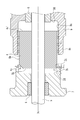
- FIG. 1 is a side cross-sectional view showing a solenoid in Example 1.
- FIG. FIG. 4 is an enlarged view around a center post, a movable part, and a sleeve. It is a sectional side view which shows the modification of a 2nd magnetoresistive part.
- the solenoid 1 includes a coil 2, a movable body 3, a first bearing 6, a second bearing 8, a center post 7, a sleeve 9, a magnetic path plate 10, a body member 11, and a base member 12. Mainly composed.
- each element constituting the solenoid 1 will be described.
- a conductor 2b enamel-coated is wound around a bobbin 2a made of an insulating material a predetermined number of times, and the outer periphery of the wound conductor 2b is covered and protected by a covering 2c made of an insulating material.
- the end of the conductor 2b is connected to the lead wire 13, and the coil 2 generates a magnetic flux when electric power is supplied from a power supply (not shown).
- the movable body 3 is formed by attaching a shaft 5 to a core 4.
- the core 4 includes a first magnetoresistive portion made of a magnetic material such as iron having a low magnetic resistance.
- the core 4 is machined to have a curved outer peripheral surface 4a, a planar end surface 4c (see FIG. 2), and a cut described later. It forms in the substantially cylindrical shape provided with the notch 4b, and the core 4 whole is comprised from the 1st magnetoresistive part.
- an isotropic magnetic powder core formed by substantially mixing iron powder having a low magnetic resistance and a resin into a substantially cylindrical shape may be used. In this case, iron powder comprises a 1st magnetoresistive part.
- the shaft 5 is made of a nonmagnetic material such as stainless steel in order to prevent leakage of magnetic flux and move the movable body efficiently. Further, the shaft 5 has a through hole 5a so that the working fluid around the movable body 3 does not become resistance when the movable body 3 moves in the axial direction, and the working fluid around the movable body 3 passes through the through hole. It can move within 5a.
- the center post 7 is made of a magnetic material such as iron and constitutes a part of a magnetic path described later.
- a recess 7a is formed at the end of the center post 7 outside the solenoid 1
- an annular flange 7b is formed inside the solenoid 1
- the first bearing 6 is non-rotatably mounted in the recess 7a.
- One end of the core 4 is accommodated in the inner space of the portion 7b.
- the sleeve 9 is made of a magnetic material such as iron and constitutes a part of a magnetic path described later.
- a concave portion 9a and a cylindrical portion 9b are formed inside the sleeve 9, and the second bearing 8 is non-rotatably mounted in the concave portion 9a, and the other end portion of the core 4 is accommodated in the inner space of the cylindrical portion 9b. .
- the magnetic path plate 10 is made of a magnetic material such as iron, and is formed in a disk shape having a hole in the center, and forms a part of the magnetic path as will be described later.
- the base member 12 is entirely or partially made of a nonmagnetic material so that the magnetic flux generated by the coil 2 does not leak.
- the body member 11 is comprised with magnetic materials, such as iron, and comprises a part of magnetic path mentioned later. Then, the base member 12 is fitted into the body member 11 in a sealing manner via the sealing member 14 and is assembled integrally.
- the center post 7 is fitted to the body member 11, the sleeve 9 is fitted to the magnetic path plate 10, and the magnetic path plate 10 is fitted to the body member 11.
- a spacer 15 made of a nonmagnetic material such as resin is disposed between the center post 7 and the sleeve 9.
- the outer peripheral surface 4a of the core 4 is not in contact with the annular flange 7b of the center post 7 and the cylindrical portion 9b of the sleeve 9, that is, between the outer peripheral surface 4a and the annular flange 7b and the cylindrical portion 9b.
- the first bearing 6 and the second bearing 8 are supported by the first bearing 6 and the second bearing 8 so as to keep the gap.
- the movable body 3 is pressed against the sleeve 9 by an external force such as an urging force (not shown).
- the center post 7 becomes the N pole and the sleeve becomes the S pole, and the magnetic flux generated in the coil 2 due to the energization flows from the body member 11 to the center post 7, the center post 7 and the core 4.
- the gap between the core 4 and the gap between the core 4 and the sleeve 9 passes from the sleeve 9 to the magnetic path plate 10 and returns to the body member 11.
- the outer peripheral surface 4a of the core 4 is supported by the first bearing 6 and the second bearing 8 so as not to contact the annular flange 7b of the center post 7 and the cylindrical portion 9b of the sleeve 9, there is no resistance.
- the movable body 3 can be driven with a small force.
- the core 4 includes a notch portion 4b as a second magnetoresistive portion that moves the movable body 3 in the radial direction by a magnetic action when the coil 2 is energized.
- a notch portion 4b as a second magnetoresistive portion that moves the movable body 3 in the radial direction by a magnetic action when the coil 2 is energized.
- the core 4 has a notch 4b formed by notching a part of the outer peripheral surface 4a and a part of the core end surface 4c.
- the notch 4b is a gap in which a working fluid such as oil is present and has a large magnetic resistance. Therefore, the magnetic flux generated by energization of the coil is difficult to pass through, and the core 4 is not attracted to the center post.
- the first magnetoresistive portion constituting the core is made of a material having a small magnetic resistance, easily allowing a magnetic flux generated by energizing the coil to pass therethrough, and attracting the core 4 to the center post.
- the gap between the outer peripheral surface 4a of the core 4 and the inner peripheral surface 7c of the annular flange 7b of the center post 7 is small, but the area where the outer peripheral surface 4a and the inner peripheral surface 7c face each other is small.
- the density of the magnetic flux from 4a to the inner peripheral surface 7c increases. Magnetic flux also flows from the end surface 4c of the core 4 to the inner peripheral surface 7c of the annular flange 7b of the center post 7 so as to reduce the magnetic flux density.
- a radial force Fr1 is generated by the magnetic flux between the outer peripheral surface 4a of the core 4 and the inner peripheral surface 7c of the annular flange 7b of the center post 7, and the inner surface of the annular flange 7b of the center post 7 is generated from the end surface 4c of the core 4.
- An axial direction Fra is generated by the magnetic flux between the peripheral surfaces 7c.
- the gap between the outer peripheral surface 4a of the core 4 and the inner peripheral surface 7c of the annular flange portion 7b of the center post 7 becomes large in the portion where the notch 4b exists, and is uneven in the circumferential direction. .
- the non-uniformity in the circumferential direction means that a notch that is the second magnetoresistive portion may be provided at one place in the circumferential direction, or the second magnetoresistive element is not evenly arranged at a plurality of places in the circumferential direction.
- the notch which is a part may be provided.
- the axial magnetic force Fa generated by the magnetic flux between the end surface 4 c of the core 4 and the inner peripheral surface 7 c of the annular flange 7 b of the center post 7 is applied as an actuator of the solenoid 1. It becomes a driving force.
- This driving force is somewhat reduced due to the presence of the notch 4b, but the actuator driving force is hardly affected because the size of the notch 4b is sufficiently smaller than the circumferential length of the outer diameter of the core.
- the notch 4b is provided in the edge part of the core 4,
- both ends of the movable body 3 are supported by the first bearing 6 and the second bearing 8, the outer peripheral surface 4 a of the core 4, the inner peripheral surface 7 c of the annular flange 7 b of the center post 7, and the outer periphery of the core 4
- the gap between the surface 4a and the inner peripheral surface 9c of the cylindrical portion 9b of the sleeve 9 can be kept substantially uniform, the core 4 does not contact the center post 7 and the sleeve 9, and the actuator is always stable. Can be driven by.
- the solenoid 1 can press the shaft 5 against the first bearing 6 and the second bearing 8, and can further reduce vibration and noise of the solenoid 1 when energized.
- the notch 4 b is provided at one end of the core 4.
- the shaft 5 can be sufficiently pressed against both the first bearing 6 and the second bearing 8 by providing notches at both ends of the core 4. As in the above-described embodiment, this is because between the notch 4b ′ of the core 4 and the inner peripheral surface 9c of the cylindrical portion 9b of the sleeve 9, and between the end surface 4c ′ of the core 4 and the cylindrical portion 9b of the sleeve 9.
- the gap between the peripheral surface 9c and the magnetic resistance is high, and most of the magnetic flux generated in the coil 2 when energized passes from the outer peripheral surface 4a of the core 4 to the inside of the cylindrical portion 9b of the sleeve 9 via the gap. Since it flows to the peripheral surface 9c, the magnetic flux flowing from the end face 4c ′ and the notch 4b ′ of the core 4 becomes very small, and an upward magnetic force in the radial direction acts due to the presence of the notch 4b ′. Then, the downwardly acting magnetic force in the radial direction by the notch portion 4b and the upward magnetic force in the radial direction by the notch portion 4b ′ act as a force for rotating the shaft 5 counterclockwise, and the shaft 5 becomes the first bearing. 6 and the second bearing 8 can be pressed with a larger force. Moreover, the notch of the both ends of the core 4 may be provided in the same phase, and a phase difference may be provided. The size and number of notches can be determined according to conditions.
- the notch 4b is provided at one end of the core 4.
- the core 4 may be provided with a convex part made of the same material as the core 4.
Landscapes
- Physics & Mathematics (AREA)
- Electromagnetism (AREA)
- Engineering & Computer Science (AREA)
- Power Engineering (AREA)
- Electromagnets (AREA)
Abstract
Description
コイルに通電したときの磁気作用によって、少なくとも第1磁気抵抗部からなるコアを軸方向に駆動するソレノイドであって、前記コアに装着される軸と、前記コアの両端部を支持する軸受と、を備え、前記磁気作用により少なくとも前記コアを径方向に可動させる力を発生させる第2磁気抵抗部を備えることを特徴としている。
この特徴によれば、通電時に、少なくともコアの径方向に作用する力によって、コアに装着された軸は軸受に押付けられるので、コアの振動を低減することができる。
前記第2磁気抵抗部は、前記第1磁気抵抗部とは異なる磁気抵抗を有することを特徴としている。
この特徴によれば、磁気抵抗の異なる材料を利用して容易に第1磁気抵抗部と第2磁気抵抗部を形成することができる。
前記第2磁気抵抗部は、前記コアの周方向に不均一に設けられていることを特徴としている。
この特徴によれば、コアが周方向の任意の箇所に押付けられ、周方向に不均一な力が加わり、コアの振れや振動を低減できる。
前記第2磁気抵抗部は、前記コアの少なくとも軸方向一方の端部に設けられることを特徴としている。
この特徴によれば、コアの端部に発生する力によって、前記コアに装着された軸を軸受に押付けることができる。
前記第2磁気抵抗部は、切欠きからなることを特徴としている。
この特徴によれば、コア全体に与える影響を最小限にして、容易にコアに装着された軸を軸受に押付けることができる。
2 コイル
3 可動体
3c 軸芯
4 コア(第1磁気抵抗部)
4b 切欠き(第2磁気抵抗部)
5 軸
6 第1軸受(軸受)
8 第2軸受(軸受)
Claims (5)
- コイルに通電したときの磁気作用によって、少なくとも第1磁気抵抗部からなるコアを軸方向に駆動するソレノイドであって、前記コアに装着される軸と、前記コアの両端部を支持する軸受と、を備え、前記磁気作用により少なくとも前記コアを径方向に可動させる力を発生させる第2磁気抵抗部を備えることを特徴とするソレノイド。
- 前記第2磁気抵抗部は、前記第1磁気抵抗部とは異なる磁気抵抗を有することを特徴とする請求項1に記載のソレノイド。
- 前記第2磁気抵抗部は、前記コアの周方向に不均一に設けられていることを特徴とする請求項1または2に記載のソレノイド。
- 前記第2磁気抵抗部は、前記コアの少なくとも軸方向一方の端部に設けられることを特徴とする請求項1ないし3のいずれかに記載のソレノイド。
- 前記第2磁気抵抗部は、切欠きからなることを特徴とする請求項1ないし4のいずれかに記載のソレノイド。
Priority Applications (4)
| Application Number | Priority Date | Filing Date | Title |
|---|---|---|---|
| EP16746460.1A EP3255641B1 (en) | 2015-02-02 | 2016-01-26 | Solenoid |
| CN201680006066.9A CN107210113B (zh) | 2015-02-02 | 2016-01-26 | 螺线管 |
| US15/543,936 US10269480B2 (en) | 2015-02-02 | 2016-01-26 | Solenoid |
| JP2016573293A JP6554492B2 (ja) | 2015-02-02 | 2016-01-26 | ソレノイド |
Applications Claiming Priority (2)
| Application Number | Priority Date | Filing Date | Title |
|---|---|---|---|
| JP2015018813 | 2015-02-02 | ||
| JP2015-018813 | 2015-02-02 |
Publications (1)
| Publication Number | Publication Date |
|---|---|
| WO2016125629A1 true WO2016125629A1 (ja) | 2016-08-11 |
Family
ID=56563980
Family Applications (1)
| Application Number | Title | Priority Date | Filing Date |
|---|---|---|---|
| PCT/JP2016/052144 Ceased WO2016125629A1 (ja) | 2015-02-02 | 2016-01-26 | ソレノイド |
Country Status (5)
| Country | Link |
|---|---|
| US (1) | US10269480B2 (ja) |
| EP (1) | EP3255641B1 (ja) |
| JP (1) | JP6554492B2 (ja) |
| CN (1) | CN107210113B (ja) |
| WO (1) | WO2016125629A1 (ja) |
Cited By (3)
| Publication number | Priority date | Publication date | Assignee | Title |
|---|---|---|---|---|
| JPWO2020137268A1 (ja) * | 2018-12-25 | 2021-11-11 | 日立Astemo株式会社 | 減衰力調整式緩衝器およびソレノイド |
| JPWO2023157503A1 (ja) * | 2022-02-17 | 2023-08-24 | ||
| WO2024224630A1 (ja) * | 2023-04-28 | 2024-10-31 | 日立Astemo株式会社 | ソレノイド |
Citations (2)
| Publication number | Priority date | Publication date | Assignee | Title |
|---|---|---|---|---|
| JP2001317653A (ja) * | 2000-02-29 | 2001-11-16 | Nok Corp | ソレノイド |
| JP2016029270A (ja) * | 2014-07-18 | 2016-03-03 | 株式会社テージーケー | 可変容量圧縮機用制御弁 |
Family Cites Families (16)
| Publication number | Priority date | Publication date | Assignee | Title |
|---|---|---|---|---|
| US2853660A (en) * | 1955-01-14 | 1958-09-23 | Westinghouse Electric Corp | Dust-tight d. c. magnet assembly |
| DE2255272B2 (de) * | 1972-11-11 | 1979-04-05 | Robert Bosch Gmbh, 7000 Stuttgart | Stellmagnet mit einem Gehäuse |
| JPS61168214A (ja) * | 1985-01-21 | 1986-07-29 | Diesel Kiki Co Ltd | 電磁比例ソレノイド |
| FR2593375B1 (fr) * | 1986-01-29 | 1988-04-08 | Seb Sa | Soupape de fonctionnement pour autocuiseur |
| DE4436616C2 (de) * | 1994-10-13 | 1996-10-17 | Kuhnke Gmbh Kg H | Hubmagnet und Verfahren zu seiner Herstellung |
| US5918635A (en) * | 1997-10-08 | 1999-07-06 | Vickers, Incorporated | Low pressure solenoid valve |
| DE10153019A1 (de) * | 2001-10-26 | 2003-05-08 | Ina Schaeffler Kg | Elektromagnet, insbesondere Proportionalmagnet zur Betätigung eines hydraulischen Ventils |
| US6929242B2 (en) * | 2003-02-11 | 2005-08-16 | Thomas Magnete Gmbh | High force solenoid and solenoid-driven actuator |
| US7209020B2 (en) * | 2003-06-09 | 2007-04-24 | Borgwarner Inc. | Variable force solenoid |
| JP4391338B2 (ja) * | 2004-06-29 | 2009-12-24 | 三菱電機株式会社 | 電磁弁 |
| JP4571189B2 (ja) * | 2005-05-31 | 2010-10-27 | ミネベア株式会社 | ロング比例ストロークフォースモータ |
| DE102009046186A1 (de) * | 2008-11-06 | 2010-05-20 | Kayaba Industry Co., Ltd. | Solenoid-Stellglied |
| JP5442980B2 (ja) * | 2008-11-06 | 2014-03-19 | カヤバ工業株式会社 | ソレノイド |
| JP5307517B2 (ja) * | 2008-11-14 | 2013-10-02 | カヤバ工業株式会社 | ソレノイド |
| JP5475982B2 (ja) | 2008-11-26 | 2014-04-16 | カヤバ工業株式会社 | ソレノイド |
| JP5998973B2 (ja) * | 2013-02-12 | 2016-09-28 | トヨタ自動車株式会社 | 電磁弁 |
-
2016
- 2016-01-26 EP EP16746460.1A patent/EP3255641B1/en active Active
- 2016-01-26 WO PCT/JP2016/052144 patent/WO2016125629A1/ja not_active Ceased
- 2016-01-26 CN CN201680006066.9A patent/CN107210113B/zh active Active
- 2016-01-26 US US15/543,936 patent/US10269480B2/en active Active
- 2016-01-26 JP JP2016573293A patent/JP6554492B2/ja active Active
Patent Citations (2)
| Publication number | Priority date | Publication date | Assignee | Title |
|---|---|---|---|---|
| JP2001317653A (ja) * | 2000-02-29 | 2001-11-16 | Nok Corp | ソレノイド |
| JP2016029270A (ja) * | 2014-07-18 | 2016-03-03 | 株式会社テージーケー | 可変容量圧縮機用制御弁 |
Non-Patent Citations (1)
| Title |
|---|
| See also references of EP3255641A4 * |
Cited By (7)
| Publication number | Priority date | Publication date | Assignee | Title |
|---|---|---|---|---|
| JPWO2020137268A1 (ja) * | 2018-12-25 | 2021-11-11 | 日立Astemo株式会社 | 減衰力調整式緩衝器およびソレノイド |
| JP7217756B2 (ja) | 2018-12-25 | 2023-02-03 | 日立Astemo株式会社 | 減衰力調整式緩衝器およびソレノイド |
| JP2023053967A (ja) * | 2018-12-25 | 2023-04-13 | 日立Astemo株式会社 | 減衰力調整式緩衝器およびソレノイド |
| JP7796063B2 (ja) | 2018-12-25 | 2026-01-08 | Astemo株式会社 | 減衰力調整式緩衝器およびソレノイド |
| JPWO2023157503A1 (ja) * | 2022-02-17 | 2023-08-24 | ||
| JP7843339B2 (ja) | 2022-02-17 | 2026-04-09 | Astemo株式会社 | ソレノイド、減衰力調整機構および減衰力調整式緩衝器 |
| WO2024224630A1 (ja) * | 2023-04-28 | 2024-10-31 | 日立Astemo株式会社 | ソレノイド |
Also Published As
| Publication number | Publication date |
|---|---|
| EP3255641A1 (en) | 2017-12-13 |
| EP3255641B1 (en) | 2021-12-29 |
| JP6554492B2 (ja) | 2019-07-31 |
| US20170352462A1 (en) | 2017-12-07 |
| CN107210113B (zh) | 2019-02-05 |
| US10269480B2 (en) | 2019-04-23 |
| CN107210113A (zh) | 2017-09-26 |
| JPWO2016125629A1 (ja) | 2017-11-09 |
| EP3255641A4 (en) | 2018-10-17 |
Similar Documents
| Publication | Publication Date | Title |
|---|---|---|
| JP6554492B2 (ja) | ソレノイド | |
| JP6642485B2 (ja) | 電磁継電器 | |
| JP6305534B2 (ja) | 無励磁作動ブレーキおよび無励磁作動ブレーキ付きモータ | |
| WO2017149726A1 (ja) | ソレノイド | |
| JP6469325B1 (ja) | 電磁アクチュエータおよび油圧調整機構 | |
| JP2011050129A (ja) | 電磁ブレーキ付モータ | |
| US11149808B2 (en) | Excitation operation brake | |
| JP4952955B2 (ja) | 無励磁作動形電磁ブレーキおよびこれを備えたモータ | |
| JP7595419B2 (ja) | ソレノイド | |
| JP6129732B2 (ja) | ブレーキモータ、および巻上機 | |
| JP2016036229A (ja) | リニアアクチュエータのブレーキ装置 | |
| JP2015021519A (ja) | 無励磁作動型電磁ブレーキ | |
| JP2017089679A (ja) | 電磁連結装置 | |
| JP5947946B2 (ja) | 無励磁作動型電磁ブレーキ | |
| JP5383579B2 (ja) | 電磁ブレーキ付き電動機 | |
| JP5810062B2 (ja) | 電磁ブレーキ | |
| US12500478B2 (en) | Rotator | |
| JP2020118214A (ja) | 電磁ブレーキ | |
| JP7236870B2 (ja) | 励磁作動ブレーキ | |
| JP6036131B2 (ja) | 負作動型電磁ブレーキ装置とその制御方法及び制御装置、駆動装置 | |
| CN114207749B (zh) | 螺线管用磁路元件 | |
| JP4807306B2 (ja) | 電磁弁 | |
| JPH0674066U (ja) | ブレーキ付モータ | |
| JP6492937B2 (ja) | 回転伝達装置 | |
| CN108736690A (zh) | 励磁装置及无励磁工作制动器 |
Legal Events
| Date | Code | Title | Description |
|---|---|---|---|
| 121 | Ep: the epo has been informed by wipo that ep was designated in this application |
Ref document number: 16746460 Country of ref document: EP Kind code of ref document: A1 |
|
| ENP | Entry into the national phase |
Ref document number: 2016573293 Country of ref document: JP Kind code of ref document: A |
|
| WWE | Wipo information: entry into national phase |
Ref document number: 15543936 Country of ref document: US |
|
| REEP | Request for entry into the european phase |
Ref document number: 2016746460 Country of ref document: EP |
|
| NENP | Non-entry into the national phase |
Ref country code: DE |