WO2016125647A1 - 制御装置、制御方法及びプログラム - Google Patents
制御装置、制御方法及びプログラム Download PDFInfo
- Publication number
- WO2016125647A1 WO2016125647A1 PCT/JP2016/052273 JP2016052273W WO2016125647A1 WO 2016125647 A1 WO2016125647 A1 WO 2016125647A1 JP 2016052273 W JP2016052273 W JP 2016052273W WO 2016125647 A1 WO2016125647 A1 WO 2016125647A1
- Authority
- WO
- WIPO (PCT)
- Prior art keywords
- refrigerant
- heat exchanger
- pressure
- water
- compressor
- Prior art date
- Legal status (The legal status is an assumption and is not a legal conclusion. Google has not performed a legal analysis and makes no representation as to the accuracy of the status listed.)
- Ceased
Links
Images

Classifications
-
- F—MECHANICAL ENGINEERING; LIGHTING; HEATING; WEAPONS; BLASTING
- F25—REFRIGERATION OR COOLING; COMBINED HEATING AND REFRIGERATION SYSTEMS; HEAT PUMP SYSTEMS; MANUFACTURE OR STORAGE OF ICE; LIQUEFACTION SOLIDIFICATION OF GASES
- F25B—REFRIGERATION MACHINES, PLANTS OR SYSTEMS; COMBINED HEATING AND REFRIGERATION SYSTEMS; HEAT PUMP SYSTEMS
- F25B47/00—Arrangements for preventing or removing deposits or corrosion, not provided for in another subclass
- F25B47/02—Defrosting cycles
- F25B47/022—Defrosting cycles hot gas defrosting
- F25B47/025—Defrosting cycles hot gas defrosting by reversing the cycle
-
- F—MECHANICAL ENGINEERING; LIGHTING; HEATING; WEAPONS; BLASTING
- F25—REFRIGERATION OR COOLING; COMBINED HEATING AND REFRIGERATION SYSTEMS; HEAT PUMP SYSTEMS; MANUFACTURE OR STORAGE OF ICE; LIQUEFACTION SOLIDIFICATION OF GASES
- F25B—REFRIGERATION MACHINES, PLANTS OR SYSTEMS; COMBINED HEATING AND REFRIGERATION SYSTEMS; HEAT PUMP SYSTEMS
- F25B49/00—Arrangement or mounting of control or safety devices
- F25B49/02—Arrangement or mounting of control or safety devices for compression type machines, plants or systems
-
- F—MECHANICAL ENGINEERING; LIGHTING; HEATING; WEAPONS; BLASTING
- F25—REFRIGERATION OR COOLING; COMBINED HEATING AND REFRIGERATION SYSTEMS; HEAT PUMP SYSTEMS; MANUFACTURE OR STORAGE OF ICE; LIQUEFACTION SOLIDIFICATION OF GASES
- F25B—REFRIGERATION MACHINES, PLANTS OR SYSTEMS; COMBINED HEATING AND REFRIGERATION SYSTEMS; HEAT PUMP SYSTEMS
- F25B13/00—Compression machines, plants or systems, with reversible cycle
-
- F—MECHANICAL ENGINEERING; LIGHTING; HEATING; WEAPONS; BLASTING
- F25—REFRIGERATION OR COOLING; COMBINED HEATING AND REFRIGERATION SYSTEMS; HEAT PUMP SYSTEMS; MANUFACTURE OR STORAGE OF ICE; LIQUEFACTION SOLIDIFICATION OF GASES
- F25B—REFRIGERATION MACHINES, PLANTS OR SYSTEMS; COMBINED HEATING AND REFRIGERATION SYSTEMS; HEAT PUMP SYSTEMS
- F25B47/00—Arrangements for preventing or removing deposits or corrosion, not provided for in another subclass
- F25B47/02—Defrosting cycles
-
- F—MECHANICAL ENGINEERING; LIGHTING; HEATING; WEAPONS; BLASTING
- F25—REFRIGERATION OR COOLING; COMBINED HEATING AND REFRIGERATION SYSTEMS; HEAT PUMP SYSTEMS; MANUFACTURE OR STORAGE OF ICE; LIQUEFACTION SOLIDIFICATION OF GASES
- F25D—REFRIGERATORS; COLD ROOMS; ICE-BOXES; COOLING OR FREEZING APPARATUS NOT OTHERWISE PROVIDED FOR
- F25D31/00—Other cooling or freezing apparatus
- F25D31/002—Liquid coolers, e.g. beverage cooler
-
- F—MECHANICAL ENGINEERING; LIGHTING; HEATING; WEAPONS; BLASTING
- F25—REFRIGERATION OR COOLING; COMBINED HEATING AND REFRIGERATION SYSTEMS; HEAT PUMP SYSTEMS; MANUFACTURE OR STORAGE OF ICE; LIQUEFACTION SOLIDIFICATION OF GASES
- F25B—REFRIGERATION MACHINES, PLANTS OR SYSTEMS; COMBINED HEATING AND REFRIGERATION SYSTEMS; HEAT PUMP SYSTEMS
- F25B2339/00—Details of evaporators; Details of condensers
- F25B2339/04—Details of condensers
- F25B2339/047—Water-cooled condensers
-
- F—MECHANICAL ENGINEERING; LIGHTING; HEATING; WEAPONS; BLASTING
- F25—REFRIGERATION OR COOLING; COMBINED HEATING AND REFRIGERATION SYSTEMS; HEAT PUMP SYSTEMS; MANUFACTURE OR STORAGE OF ICE; LIQUEFACTION SOLIDIFICATION OF GASES
- F25B—REFRIGERATION MACHINES, PLANTS OR SYSTEMS; COMBINED HEATING AND REFRIGERATION SYSTEMS; HEAT PUMP SYSTEMS
- F25B2500/00—Problems to be solved
- F25B2500/28—Means for preventing liquid refrigerant entering into the compressor
-
- F—MECHANICAL ENGINEERING; LIGHTING; HEATING; WEAPONS; BLASTING
- F25—REFRIGERATION OR COOLING; COMBINED HEATING AND REFRIGERATION SYSTEMS; HEAT PUMP SYSTEMS; MANUFACTURE OR STORAGE OF ICE; LIQUEFACTION SOLIDIFICATION OF GASES
- F25B—REFRIGERATION MACHINES, PLANTS OR SYSTEMS; COMBINED HEATING AND REFRIGERATION SYSTEMS; HEAT PUMP SYSTEMS
- F25B2700/00—Sensing or detecting of parameters; Sensors therefor
- F25B2700/19—Pressures
- F25B2700/193—Pressures of the compressor
- F25B2700/1931—Discharge pressures
-
- F—MECHANICAL ENGINEERING; LIGHTING; HEATING; WEAPONS; BLASTING
- F25—REFRIGERATION OR COOLING; COMBINED HEATING AND REFRIGERATION SYSTEMS; HEAT PUMP SYSTEMS; MANUFACTURE OR STORAGE OF ICE; LIQUEFACTION SOLIDIFICATION OF GASES
- F25B—REFRIGERATION MACHINES, PLANTS OR SYSTEMS; COMBINED HEATING AND REFRIGERATION SYSTEMS; HEAT PUMP SYSTEMS
- F25B2700/00—Sensing or detecting of parameters; Sensors therefor
- F25B2700/19—Pressures
- F25B2700/193—Pressures of the compressor
- F25B2700/1933—Suction pressures
-
- F—MECHANICAL ENGINEERING; LIGHTING; HEATING; WEAPONS; BLASTING
- F25—REFRIGERATION OR COOLING; COMBINED HEATING AND REFRIGERATION SYSTEMS; HEAT PUMP SYSTEMS; MANUFACTURE OR STORAGE OF ICE; LIQUEFACTION SOLIDIFICATION OF GASES
- F25B—REFRIGERATION MACHINES, PLANTS OR SYSTEMS; COMBINED HEATING AND REFRIGERATION SYSTEMS; HEAT PUMP SYSTEMS
- F25B2700/00—Sensing or detecting of parameters; Sensors therefor
- F25B2700/21—Temperatures
- F25B2700/2103—Temperatures near a heat exchanger
Definitions
- the present invention relates to a control device, a control method, and a program.
- Priority is claimed on Japanese Patent Application No. 2015-018384, filed Feb. 2, 2015, the content of which is incorporated herein by reference.
- Patent Document 1 discloses a related technology.
- the device disclosed in Patent Document 1 performs reverse cycle operation so that the compressor does not suck in the liquid refrigerant which has fallen to the lower temperature among the indoor and outdoor units, and liquid compression and the like that occur when the compressor takes in the liquid refrigerant Prevent oil forming.
- the operation of a cooling cycle in which water is cooled using a water heat exchanger is started when the ambient temperature is low, such as winter.
- the temperature of the refrigerant may decrease, and the water to be cooled may be frozen.
- An object of the present invention is to provide a control device, a control method, and a program that can solve the above-mentioned problems.
- the control device causes the air heat exchanger to send out the refrigerant heat-exchanged with the outside air, and the water and the refrigerant sent out from the air heat exchanger to exchange heat with each other.
- Chilling comprising a water heat exchanger for cooling, a compressor for compressing the refrigerant and delivering the compressed refrigerant, and a first refrigerant pipe for delivering the refrigerant delivered from the compressor to the air heat exchanger
- a controller for a unit, wherein, when the cooling cycle for cooling the water is operated using the water heat exchanger, the pressure of the refrigerant in the first refrigerant pipe causes the compressor and the water heat exchanger to operate.
- the control device in the first aspect detects a pressure of the refrigerant in the first refrigerant pipe, and a first pressure sensor that detects the pressure of the refrigerant in the second refrigerant pipe.
- a second pressure sensor, and the control unit obtains a differential pressure obtained by subtracting the pressure of the refrigerant detected by the first pressure sensor from the pressure of the refrigerant detected by the second pressure sensor.
- the control unit in the control device according to the second aspect, in the case where the chilling unit includes a plurality of sets of air heat exchangers, water heat exchangers and compressors, the control unit is configured to The operation of the reverse cycle of the cooling cycle may be switched to the operation of the cooling cycle at different timings for each.
- the control method comprises: an air heat exchanger for delivering the refrigerant heat-exchanged with the outside air; heat exchange between the refrigerant and the water delivered from the air heat exchanger; Chilling comprising a water heat exchanger for cooling, a compressor for compressing the refrigerant and delivering the compressed refrigerant, and a first refrigerant pipe for delivering the refrigerant delivered from the compressor to the air heat exchanger
- a control method of a controller for a unit comprising: operating a cooling cycle for cooling the water using the water heat exchanger, in a refrigerant pipe between the compressor and the air heat exchanger
- the differential pressure obtained by reducing the pressure of the refrigerant in the refrigerant pipe between the compressor and the water heat exchanger from the pressure of the refrigerant is a state in which the refrigerant circulates and the water does not freeze.
- the chilling unit controls the operation of the reverse cycle of the cooling cycle before controlling the chilling unit to start the operation of the cooling cycle
- the program causes the air heat exchanger to send out the refrigerant that has exchanged heat with the outside air, and causes the heat exchange between the refrigerant and the water sent out from the air heat exchanger to carry out the water.
- Chilling comprising the water heat exchanger to be cooled, a compressor for compressing the refrigerant and delivering the compressed refrigerant, and a first refrigerant pipe for delivering the refrigerant delivered from the compressor to the air heat exchanger
- the computer for the unit is operated in a cooling cycle for cooling the water using the water heat exchanger
- the pressure of the refrigerant in the refrigerant pipe between the compressor and the air heat exchanger causes the compressor to operate.
- control device control method and program, it is possible to prevent the cooling water from freezing when starting the operation of the cooling cycle in the chilling unit.
- FIG. 5 is a diagram showing the configuration of a chilling unit according to an embodiment of the present invention. It is a figure explaining operation of a cooling cycle which a chilling unit performs in one embodiment of the present invention. It is a figure explaining operation of a heating cycle performed before a chilling unit by one embodiment of the present invention starts operation of a cooling cycle.
- the chilling unit 1 includes an air heat exchanger 101, a water heat exchanger 201, a first pressure sensor 202, a second pressure sensor 203, and four directions.
- a valve 207, an accumulator 208, a compressor 209, a compressor motor 210, an expansion valve 215, and a controller 216 are provided.
- the air heat exchanger 101 functions as a condenser when operating a cooling cycle for cooling water by the water heat exchanger 201.
- the air heat exchanger 101 functions as an evaporator when performing the operation of the heating cycle which is the reverse of the cooling cycle.
- the water heat exchanger 201 functions as an evaporator when performing the operation of the cooling cycle.
- the water heat exchanger 201 functions as a condenser when operating the heating cycle.
- the first pressure sensor 202 detects the pressure of the refrigerant in the water heat exchanger 201 connected to the four-way valve 207.
- the first pressure sensor 202 detects the pressure of the refrigerant in the water heat exchanger 201 connected to the four-way valve 207 before starting the operation of the cooling cycle.
- the second pressure sensor 203 detects the pressure of the refrigerant in the air heat exchanger 101 connected to the four-way valve 207.
- the second pressure sensor 203 detects the pressure of the refrigerant in the air heat exchanger 101 connected to the four-way valve 207 before starting the operation of the cooling cycle.
- the four-way valve 207 has four valves. One of the four valves is connected to the water heat exchanger 201. Another one of the four valves is connected to the accumulator 208. Another one of the four valves is connected to the air heat exchanger 101. The remaining one of the four valves is connected to the compressor 209.
- An accumulator 208 is provided between the four-way valve 207 and the compressor motor 210.
- the accumulator 208 prevents the refrigerant that can not be gasified by the evaporator from being sucked into the compressor 209 as a liquid.
- the compressor 209 is provided between the compressor motor 210 and the accumulator 208.
- the compressor 209 uses the compressor motor 210 as a motive power source, and delivers the input gas refrigerant as a gas refrigerant having a temperature higher than that at the time of input and a high pressure.
- the compressor motor 210 is provided between the accumulator 208 and the compressor 209.
- the compressor motor 210 operates the compressor 209.
- Expansion valve 215 is provided between air heat exchanger 101 and water heat exchanger 201.
- the expansion valve 215 makes the liquid refrigerant of the pressure P, which is the input temperature T, a temperature lower than the temperature T and lower than the pressure P.
- the controller 216 includes a controller 217.
- the control unit 217 controls the respective functional units of the chilling unit 1 to set the temperature of the water cooled by the water heat exchanger 201 to a desired temperature.
- the control unit 217 controls the valve opening degree of the expansion valve 215 to perform pressure reduction adjustment and flow rate adjustment.
- the control unit 217 controls the pressure of the refrigerant in the water heat exchanger 201 connected to the four-way valve 207 and the air connected to the four-way valve 207 before starting the operation of the cooling cycle in the chilling unit 1.
- the pressure difference between the heat exchanger 101 and the pressure of the refrigerant is controlled to a predetermined pressure or higher.
- the control unit 217 determines that the differential pressure obtained by subtracting the pressure of the refrigerant detected by the first pressure sensor 202 from the pressure of the refrigerant detected by the second pressure sensor 203 is higher than a predetermined differential pressure. When it is low, the heating cycle is operated in the chilling unit 1. In addition, the control unit 217 causes the differential pressure obtained by subtracting the pressure of the refrigerant detected by the first pressure sensor 202 from the pressure of the refrigerant detected by the second pressure sensor 203 to circulate the refrigerant and prevent the water from freezing. After reaching a predetermined differential pressure or more, the cooling cycle is operated in the chilling unit 1.
- the differential pressure obtained by subtracting the pressure of the refrigerant detected by the first pressure sensor 202 from the pressure of the refrigerant detected by the second pressure sensor 203 causes the chilling unit 1 to reach an equilibrium state.
- the control to switch from the operation of the reverse cycle of the cooling cycle to the operation of the cooling cycle in the chilling unit 1 at the timing of the differential pressure of the predetermined range where the refrigerant of the same circulation flow rate as the circulation flow rate of Do.
- the compressor 209 changes the input gas refrigerant to a high temperature and high pressure gas refrigerant than at the time of input and controls the four-way valve It is delivered to the air heat exchanger 101 via 207.
- the air heat exchanger 101 which functions as a condenser, exchanges heat with the outside air. At this time, the temperature of the refrigerant is higher than the outside air temperature. Therefore, the air heat exchanger 101 converts the input refrigerant into a refrigerant having a temperature lower than that at the time of input and sends it to the expansion valve 215.
- the expansion valve 215 performs pressure reduction adjustment and flow rate adjustment of the input refrigerant, and sends it to the water heat exchanger 201 as a low temperature, low pressure refrigerant.
- the water heat exchanger 201 functioning as an evaporator exchanges heat of the refrigerant input from the expansion valve 215 with water and the outside air. At this time, the temperature of the refrigerant is lower than the temperatures of water and ambient air. Therefore, the water heat exchanger 201 cools the water and raises the temperature and pressure of the refrigerant.
- the water heat exchanger 201 delivers the refrigerant to the accumulator 208 via the four-way valve 207.
- the accumulator 208 prevents the refrigerant that can not be gasified by the evaporator from being sucked into the compressor 209 as a liquid. As a result, the accumulator 208 delivers only the gas refrigerant to the compressor 209 via the compressor motor 210.
- the compressor 209 converts the input gas refrigerant into a gas refrigerant having a temperature higher than that at the time of input and a high pressure, and performs water heat exchange via the four-way valve 207 It sends to the container 201.
- the water heat exchanger 201 which functions as a condenser exchanges heat between the refrigerant and water and the outside air. At this time, the temperature of the refrigerant is higher than the water and the outside air temperature. Therefore, the water heat exchanger 201 sends the input refrigerant to the expansion valve 215 as a refrigerant having a temperature lower than that at the time of input.
- the expansion valve 215 performs pressure reduction adjustment and flow rate adjustment of the input refrigerant, and sends it to the air heat exchanger 101 as a low temperature, low pressure refrigerant.
- the air heat exchanger 101 that functions as an evaporator causes the refrigerant input from the expansion valve 215 to exchange heat with the outside air. At this time, the temperature of the refrigerant is lower than the outside air temperature. Therefore, the air heat exchanger 101 raises the temperature and pressure of the refrigerant.
- the air heat exchanger 101 delivers the refrigerant to the accumulator 208 via the four-way valve 207.
- the accumulator 208 prevents the refrigerant that can not be gasified by the evaporator from being sucked into the compressor 209 as a liquid. As a result, the accumulator 208 delivers only the gas refrigerant to the compressor 209 via the compressor motor 210.
- control unit 217 does not operate the heating cycle before starting the operation of the cooling cycle and explains the case where the control of operating the cooling cycle immediately is performed. Do.
- the compressor 209 converts the input gas refrigerant into a gas refrigerant having a higher temperature and pressure than that at the time of input and makes the four-way valve 207 It sends out to the air heat exchanger 101 via.
- the air heat exchanger 101 which functions as a condenser, exchanges heat with the outside air. At this time, the temperature of the refrigerant is higher than the outside air temperature. Therefore, the air heat exchanger 101 converts the input refrigerant into a refrigerant having a temperature lower than that at the time of input and sends it to the expansion valve 215.
- the expansion valve 215 performs pressure reduction adjustment and flow rate adjustment of the input refrigerant, and sends it to the water heat exchanger 201 as a low temperature, low pressure refrigerant.
- the water heat exchanger 201 functioning as an evaporator exchanges heat of the refrigerant input from the expansion valve 215 with water and the outside air. At this time, the temperature of the refrigerant is lower than the temperatures of water and outside air. Therefore, the water heat exchanger 201 cools the water and raises the temperature and pressure of the refrigerant.
- the water heat exchanger 201 delivers the refrigerant to the accumulator 208 via the four-way valve 207.
- the accumulator 208 prevents the refrigerant that can not be gasified by the evaporator from being sucked into the compressor 209 as a liquid. As a result, the accumulator 208 delivers only the gas refrigerant to the compressor 209 via the compressor motor 210. As a result, the refrigerant flows inside the chilling unit 1 in the direction of the solid arrow shown in FIG.
- operation of the cooling cycle which the chilling unit 1 shown in FIG. 2 performs demonstrates the relationship between the time when the refrigerant flows through the inside of the chilling unit 1 in the direction of the solid arrow shown in FIG. Is shown.
- the horizontal axis is time.
- the vertical axis is the pressure of the refrigerant.
- the pressure P1 is the pressure of the refrigerant detected by the first pressure sensor 202.
- the pressure P2 is the pressure of the refrigerant detected by the second pressure sensor 203.
- Time 0 is a reference time. At time 0, the compressor 209 is not operating. At time 0, the refrigerant in the chilling unit 1 is in an equilibrium state. In the case of FIG.
- Time t1a is the time when the compressor 209 starts operation.
- the time t2a is a time at which the pressure P1 becomes minimum.
- Time t3a is the time at which the pressure P1 returns to 0.7 MPa, which is the pressure at time 0.
- Time t4a is a time when the refrigerant in the chilling unit 1 is in an equilibrium state during operation of the compressor 209. The operation of the chilling unit 1 at each time will be described below.
- the compressor 209 is not operating. From time 0 to time t1a, the compressor 209 is not operating. From time 0 to time t1a, the refrigerant in the chilling unit 1 is in an equilibrium state. When the compressor 209 starts operating at time t1a, the compressor 209 inputs a refrigerant. The compressor 209 turns the refrigerant into a high-pressure refrigerant at a higher temperature than the refrigerant at the time of input, and delivers the refrigerant to the air heat exchanger 101 via the four-way valve 207. At this time, the refrigerant passes through a second pressure sensor 203 provided in a refrigerant pipe between the four-way valve 207 and the air heat exchanger 101.
- the air heat exchanger 101 functioning as a condenser receives the refrigerant that has passed through the second pressure sensor 203.
- the air heat exchanger 101 exchanges the heat of the input refrigerant with the outside air to make it a refrigerant having a temperature lower than that at the time of input.
- the air heat exchanger 101 delivers the refrigerant to the expansion valve 215.
- the expansion valve 215 performs pressure reduction adjustment and flow rate adjustment to make the input refrigerant into a low temperature, low pressure refrigerant, and sends it to the water heat exchanger 201.
- the temperature of the refrigerant at this time is lower than the temperatures of water and outside air in the water heat exchanger 201.
- the water heat exchanger 201 that functions as an evaporator receives refrigerant from the expansion valve 215.
- the air heat exchanger 101 exchanges the heat of the input refrigerant with water and the outside air.
- the temperature of the refrigerant input to the water heat exchanger 201 is lower than the temperatures of water and ambient air in the water heat exchanger 201. Therefore, the temperature and pressure of the refrigerant rise and the water is cooled.
- the water heat exchanger 201 delivers the refrigerant to the accumulator 208 via the four-way valve 207.
- the refrigerant passes through the first pressure sensor 202 provided in the refrigerant pipe between the water heat exchanger 201 and the four-way valve 207.
- the pressure difference obtained by subtracting the pressure of the refrigerant detected by the first pressure sensor 202 from the pressure of the refrigerant detected by the second pressure sensor 203 in the chilling unit 1 Is small. Therefore, the flow rate per unit time of the refrigerant circulating in the chilling unit 1 is small.
- the amount of refrigerant compressed by the compressor 209 is also small, and the compression ratio at which the compressor 209 compresses the refrigerant is low.
- the temperature at which the compressor 209 heats the refrigerant is lower than the temperature at which the air heat exchanger 101 and the expansion valve 215 perform pressure reduction adjustment and flow rate adjustment to cool the refrigerant, and the temperature of the refrigerant detected by the first pressure sensor 202
- the pressure P1 gradually decreases from time t1a.
- the accumulator 208 prevents the refrigerant that can not be gasified by the evaporator from being sucked into the compressor 209 as a liquid. As a result, the accumulator 208 delivers only the gas refrigerant to the compressor 209 via the compressor motor 210.
- the flow rate per unit time of the refrigerant circulating in the chilling unit 1 increases, and the temperature at which the compressor 209 compresses and heats the refrigerant increases. Therefore, the temperature of the refrigerant that the compressor 209 delivers to the air heat exchanger 101 via the four-way valve 207 rises.
- the temperature at which the compressor 209 heats the refrigerant is higher than the temperature at which the air heat exchanger 101 and the expansion valve 215 cool the refrigerant. Therefore, the temperature of the refrigerant in the refrigerant pipe between the water heat exchanger 201 and the four-way valve 207 rises, and the pressure P1 of the refrigerant detected by the first pressure sensor 202 rises.
- the pressure P1 of the refrigerant detected by the first pressure sensor 202 and the pressure P2 of the refrigerant detected by the second pressure sensor 203 rise transiently.
- the pressure P1 of the refrigerant detected by the first pressure sensor 202 becomes 0.7 MPa which is the same as the pressure at time 0 at time t3a and continues to rise.
- Each of the pressure P1 of the refrigerant detected by the first pressure sensor 202 and the pressure P2 of the refrigerant detected by the second pressure sensor 203 becomes a steady state designed for operation of the cooling cycle at time t4a.
- heat exchange in the water heat exchanger 201 may freeze the water. That is, in the chilling unit 1, when the control unit 217 performs control of operating the cooling cycle for cooling water by the water heat exchanger 201 immediately without performing control of operating the heating cycle, it is an object to be cooled. Water may freeze.
- the control unit 217 operates the heating cycle before the control unit 217 starts the operation of the cooling cycle, and the pressure of the refrigerant detected by the second pressure sensor 203 is first A case where the differential pressure obtained by reducing the pressure (P2> P1) of the refrigerant detected by the pressure sensor 202 is controlled to be equal to or higher than a predetermined differential pressure will be described.
- the compressor 209 converts the input gas refrigerant into a gas refrigerant having a higher temperature and pressure than that at the time of input and makes the four-way valve 207 It sends out to the water heat exchanger 201 via.
- the water heat exchanger 201 which functions as a condenser exchanges heat with the water. At this time, the temperature of the refrigerant is higher than the water temperature. Therefore, the water heat exchanger 201 sends the input refrigerant to the expansion valve 215 as a refrigerant having a temperature lower than that at the time of input.
- the expansion valve 215 performs pressure reduction adjustment and flow rate adjustment of the input refrigerant, and sends it to the air heat exchanger 101 as a low temperature, low pressure refrigerant.
- the air heat exchanger 101 that functions as an evaporator causes the refrigerant input from the expansion valve 215 to exchange heat with the outside air. At this time, the temperature of the refrigerant is lower than the outside air temperature. Therefore, the air heat exchanger 101 raises the temperature of the refrigerant. Then, the air heat exchanger 101 delivers the refrigerant to the accumulator 208 via the four-way valve 207.
- the accumulator 208 prevents the refrigerant that can not be gasified by the evaporator from being sucked into the compressor 209 as a liquid.
- the accumulator 208 delivers only the gas refrigerant to the compressor 209 via the compressor motor 210.
- the control unit 217 switches the control for operating the heating cycle to the control for operating the cooling cycle.
- the refrigerant flows inside the chilling unit 1 in the direction of the solid arrow shown in FIG.
- the figure for explaining the operation of the heating cycle performed before the chilling unit 1 shown in FIG. 3 starts the operation of the cooling cycle is the case where the refrigerant flows inside the chilling unit 1 in the direction of the solid arrow shown in FIG.
- the relationship between the time and the pressure of the refrigerant is shown.
- the horizontal axis is time.
- the vertical axis is the pressure of the refrigerant.
- the pressure P1 is the pressure of the refrigerant detected by the first pressure sensor 202.
- the pressure P2 is the pressure of the refrigerant detected by the second pressure sensor 203.
- Time 0 is a reference time. At time 0, the compressor 209 is not operating. At time 0, the refrigerant in the chilling unit 1 is in an equilibrium state. In the case of FIG.
- each of the pressure P1 and the pressure P2 at time 0 is 0.7 MPa.
- Time t1b is the time at which the compressor 209 starts operating.
- Time t2b is a time at which the differential pressure obtained by subtracting the pressure P1 of the refrigerant detected by the first pressure sensor 202 from the pressure P2 of the refrigerant detected by the second pressure sensor 203 becomes maximum.
- the differential pressure obtained by subtracting the pressure P1 of the refrigerant detected by the first pressure sensor 202 from the pressure P2 of the refrigerant detected by the second pressure sensor 203 at time t3b is the difference between the pressure P2 and the pressure P1 at time t2b
- a differential pressure indicating that the refrigerant circulates in the chilling unit 1 and the differential pressure (for example, 0.3 to 0.6 MPa) within a predetermined range where the water to be cooled does not freeze (for example, 0.3 to 0.6 MPa)
- time t3b is the time at which the control unit 217 switches from control for operating the heating cycle to control for operating the cooling cycle.
- the time t4b is a time when the pressure P1 and the pressure P2 coincide with each other.
- Time t5b is the time when the refrigerant in the chilling unit 1 is in an equilibrium state during operation of the compressor 209. The operation of the chilling unit 1 at each time will be described below.
- the compressor 209 is not operating. From time 0 to time t1 b, the compressor 209 is not operating. From time 0 to time t1 b, the refrigerant in the chilling unit 1 is in an equilibrium state.
- the compressor 209 starts operating at time t1b, the compressor 209 inputs a refrigerant.
- the compressor 209 turns the input refrigerant into a refrigerant having a temperature higher than that of the input refrigerant and a high pressure, and sends the refrigerant to the water heat exchanger 201 through the four-way valve 207. At this time, the refrigerant passes through a first pressure sensor 202 provided in a refrigerant pipe between the four-way valve 207 and the water heat exchanger 201.
- the water heat exchanger 201 functioning as a condenser receives the refrigerant that has passed through the first pressure sensor 202.
- the water heat exchanger 201 exchanges the heat of the input refrigerant with water and the outside air, and makes it a refrigerant having a temperature lower than that at the time of input. At this time, the temperature of water rises.
- the water heat exchanger 201 delivers the refrigerant to the expansion valve 215.
- the expansion valve 215 performs pressure reduction adjustment and flow rate adjustment to make the input refrigerant into a low temperature, low pressure refrigerant, and sends it to the air heat exchanger 101.
- the temperature of the refrigerant at this time is lower than the temperature of the outside air in the air heat exchanger 101.
- the air heat exchanger 101 functioning as an evaporator inputs the refrigerant from the expansion valve 215.
- the air heat exchanger 101 exchanges the heat of the input refrigerant with the outside air.
- the temperature of the refrigerant input to the air heat exchanger 101 is lower than the temperature of the outside air in the air heat exchanger 101. Therefore, the temperature and pressure of the refrigerant rise.
- the air heat exchanger 101 delivers the refrigerant to the accumulator 208 via the four-way valve 207.
- the refrigerant passes through a second pressure sensor 203 provided in a refrigerant pipe between the air heat exchanger 101 and the four-way valve 207. Therefore, the pressure P2 of the refrigerant detected by the second pressure sensor 203 gradually decreases from time t1 b.
- the accumulator 208 prevents the refrigerant that can not be gasified by the evaporator from being sucked into the compressor 209 as a liquid. As a result, the accumulator 208 delivers only the gas refrigerant to the compressor 209 via the compressor motor 210.
- the temperature of the refrigerant that the compressor 209 delivers to the water heat exchanger 201 via the four-way valve 207 rises.
- the pressure P1 of the refrigerant detected by the first pressure sensor 202 rises, and the pressure P2 of the refrigerant detected by the second pressure sensor 203 decreases.
- the differential pressure obtained by subtracting the pressure P1 of the refrigerant detected by the first pressure sensor 202 from the pressure P2 of the refrigerant detected by the second pressure sensor 203 becomes maximum.
- the temperature rise of the refrigerant that the compressor 209 sends to the water heat exchanger 201 via the four-way valve 207 becomes larger than the decrease of the temperature of the refrigerant cooled by the water heat exchanger 201 and the expansion valve 215.
- the temperature of the refrigerant in the refrigerant pipe between the air heat exchanger 101 and the four-way valve 207 rises, and the pressure P2 of the refrigerant detected by the second pressure sensor 203 rises.
- the control unit 217 heats up at time t3 b when the refrigerant circulates in the chilling unit 1 and the differential pressure of the water to be cooled does not freeze. Switching from control for operating the cycle to control for operating the cooling cycle.
- the pressure difference obtained by subtracting the pressure P1 of the refrigerant detected by the first pressure sensor 202 from the pressure P2 of the refrigerant detected by the second pressure sensor 203 causes the refrigerant to circulate in the chilling unit 1 and to be cooled
- the controller 217 may switch the control of the operation of the heating cycle to the control of the operation of the cooling cycle as long as the water does not freeze and is in a state not lower than the predetermined differential pressure.
- the refrigerant pipe between the air heat exchanger 101 and the four-way valve 207 is connected to the output of the compressor 209 and the water heat exchanger 201
- the refrigerant pipe between the two-way valve 207 is connected to the input of the compressor 209 via the accumulator 208 and the compressor motor 210.
- the compressor 209 inputs the refrigerant from the refrigerant pipe between the water heat exchanger 201 and the four-way valve 207 via the accumulator 208 and the compressor motor 210.
- the compressor 209 turns the input refrigerant into a refrigerant having a temperature higher than that of the input refrigerant and a high pressure, and sends it to the air heat exchanger 101 via the four-way valve 207.
- the refrigerant passes through a second pressure sensor 203 provided in a refrigerant pipe between the four-way valve 207 and the air heat exchanger 101. Therefore, the pressure P2 of the refrigerant detected by the second pressure sensor 203 is increased.
- the air heat exchanger 101 functioning as a condenser receives the refrigerant that has passed through the second pressure sensor 203.
- the air heat exchanger 101 exchanges the heat of the input refrigerant with the outside air to make it a refrigerant having a temperature lower than that at the time of input.
- the air heat exchanger 101 delivers the refrigerant to the expansion valve 215.
- the expansion valve 215 performs pressure reduction adjustment and flow rate adjustment to make the input refrigerant into a low temperature, low pressure refrigerant, and sends it to the water heat exchanger 201.
- the temperature of the refrigerant at this time is lower than the temperatures of water and outside air in the water heat exchanger 201.
- the water heat exchanger 201 that functions as an evaporator receives refrigerant from the expansion valve 215.
- the water heat exchanger 201 exchanges the heat of the input refrigerant with water and the outside air.
- the temperature of the refrigerant input to the water heat exchanger 201 is lower than the temperatures of water and ambient air in the water heat exchanger 201. Therefore, the temperature and pressure of the refrigerant rise and the water is cooled.
- the water heat exchanger 201 delivers the refrigerant to the accumulator 208 via the four-way valve 207. At this time, the refrigerant passes through the first pressure sensor 202 provided in the refrigerant pipe between the water heat exchanger 201 and the four-way valve 207. Therefore, the pressure P1 of the refrigerant detected by the first pressure sensor 202 decreases from time t3b.
- the accumulator 208 prevents the refrigerant that can not be gasified by the evaporator from being sucked into the compressor 209 as a liquid. As a result, the accumulator 208 delivers only the gas refrigerant to the compressor 209 via the compressor motor 210.
- the temperature of the refrigerant that the compressor 209 delivers to the air heat exchanger 101 via the four-way valve 207 rises.
- the pressure P1 of the refrigerant detected by the first pressure sensor 202 at time t4b matches the pressure P2 of the refrigerant detected by the second pressure sensor 203.
- the pressure P1 of the refrigerant detected by the first pressure sensor 202 and the pressure P2 of the refrigerant detected by the second pressure sensor 203 rise.
- the pressure P1 of the refrigerant detected by the first pressure sensor 202 and the pressure P2 of the refrigerant detected by the second pressure sensor 203 are substantially in equilibrium at time t5b.
- the operation of the heating cycle is performed before the control unit 217 starts the operation of the cooling cycle, and the pressure of the refrigerant detected by the second pressure sensor 203
- the differential pressure obtained by reducing the pressure of the refrigerant detected by the first pressure sensor 202 is controlled to be equal to or higher than a predetermined differential pressure, it is possible to prevent the water to be cooled from freezing.
- the control unit 217 starts the operation of the cooling cycle and cools the water. Before starting the operation of the cooling cycle which cools water using 201, the operation of the heating cycle which is the reverse cycle of the cooling cycle is performed.
- the controller 217 causes the compressor 209 and the water heat exchanger 201 to have a pressure P2 lower than the pressure P2 of the refrigerant from the pressure P2 of the refrigerant in the refrigerant pipe between the compressor 209 and the air heat exchanger 101 when operating the cooling cycle.
- the differential pressure obtained by reducing the pressure P1 of the refrigerant in the refrigerant pipe during the period is controlled to a state of a predetermined differential pressure or more in which the refrigerant circulates and the water does not freeze.
- the control unit 217 balances the pressure difference obtained by subtracting the pressure of the refrigerant detected by the first pressure sensor 202 from the pressure of the refrigerant detected by the second pressure sensor 203 from the chilling unit 1.
- the operation is switched from the operation of the reverse cycle of the cooling cycle to the operation of the cooling cycle at a timing at which the differential pressure of the predetermined range can flow the refrigerant having the same circulation flow rate as the circulation flow rate of the refrigerant when the state is reached.
- the control device 216 can prevent the cooling water from freezing when starting the operation of the cooling cycle without adding a special function in the chilling unit 1.
- the control unit 217 controls the heating cycle operation to the cooling cycle at different timings for each of the plurality of sets. Control to switch to operation. In this way, in the chilling unit 1, the control device 216 performs the operation of the heating cycle on the two or more sets of air heat exchangers 101, the water heat exchanger 201, and the compressor 209, which is the water to be cooled.
- control unit 217 sets the differential pressure obtained by subtracting the pressure of the refrigerant detected by the first pressure sensor 202 from the pressure of the refrigerant detected by the second pressure sensor 203 to be lower than a predetermined differential pressure. , And may perform defrost control. In this way, the control device 216 can prevent the cooling water from freezing when starting the operation of the cooling cycle without adding a special function in the chilling unit 1.
- control device 216 described above has a computer system inside.
- the process of the process described above is stored in the form of a program in a computer readable recording medium, and the process is performed by the computer reading and executing the program.
- the computer-readable recording medium refers to a magnetic disk, a magneto-optical disk, a CD-ROM, a DVD-ROM, a semiconductor memory and the like.
- the computer program may be distributed to a computer through a communication line, and the computer receiving the distribution may execute the program.
- the program may realize part of the functions described above.
- the program may be a file capable of realizing the above-described functions in combination with a program already recorded in a computer system, a so-called difference file (difference program).
- the chilling unit in the chilling unit, it is possible to prevent the water to be cooled from freezing when starting the operation of the cooling cycle.
Landscapes
- Engineering & Computer Science (AREA)
- Physics & Mathematics (AREA)
- Mechanical Engineering (AREA)
- Thermal Sciences (AREA)
- General Engineering & Computer Science (AREA)
- Air Conditioning Control Device (AREA)
- Chemical & Material Sciences (AREA)
- Combustion & Propulsion (AREA)
- Compression-Type Refrigeration Machines With Reversible Cycles (AREA)
Abstract
制御装置(216)は、制御部(217)を備える。制御部は、水熱交換器(201)を用いて水を冷却する冷却サイクルの運転をさせるときに、コンプレッサ(209)と空気熱交換器(101)との間の冷媒管における冷媒の圧力から前記コンプレッサと前記水熱交換器との間の冷媒管における冷媒の圧力を減じることにより得られる差圧を、前記冷媒が循環しかつ前記水が凍結しない所定の差圧以上の状態に制御し、前記冷却サイクルの運転を行う場合に外気温度が前記水を凝固点以下の温度とする外気温度であるとき、チリングユニット(1)に前記冷却サイクルの運転を開始させる前に、前記チリングユニットに前記冷却サイクルの逆サイクルの運転をさせる。
Description
本発明は、制御装置、制御方法及びプログラムに関する。
本願は、2015年2月2日に、日本に出願された特願2015-018384号に基づき優先権を主張し、その内容をここに援用する。
本願は、2015年2月2日に、日本に出願された特願2015-018384号に基づき優先権を主張し、その内容をここに援用する。
水熱交換器により水を冷却する冷却サイクルの運転を行うチリングユニットがある。チリングユニットでは、冷媒を使用して水を冷却する。
特許文献1には、関連する技術が開示されている。特許文献1に開示の装置は、室内外ユニットのうち温度の低い方に寝込んだ液冷媒を、コンプレッサが吸い込まないよう、逆サイクル運転とし、コンプレッサが液冷媒を取り込んだときに発生する液圧縮やオイルフォーミングを防止する。
特許文献1には、関連する技術が開示されている。特許文献1に開示の装置は、室内外ユニットのうち温度の低い方に寝込んだ液冷媒を、コンプレッサが吸い込まないよう、逆サイクル運転とし、コンプレッサが液冷媒を取り込んだときに発生する液圧縮やオイルフォーミングを防止する。
チリングユニットにおいて、冬などの外気温が低い時期に水熱交換器を用いて水を冷却する冷却サイクルの運転を開始する。この場合、冷却サイクルの運転時にコンプレッサの低圧側となる水熱交換器において、冷媒の温度が低下し、冷却対象の水が凍結してしまう可能性がある。
本発明は、上記の課題を解決することのできる制御装置、制御方法及びプログラムを提供することを目的としている。
本発明の第1の態様によれば、制御装置は、外気と熱交換した冷媒を送出する空気熱交換器と、前記空気熱交換器から送出された冷媒と水とを熱交換させて前記水を冷却する水熱交換器と、前記冷媒を圧縮し前記圧縮された冷媒を送出するコンプレッサと、前記コンプレッサから送出された冷媒を前記空気熱交換器に送出する第1冷媒管と、を備えるチリングユニットのための制御装置であって、前記水熱交換器を用いて前記水を冷却する冷却サイクルの運転をさせるときに、前記第1冷媒管における冷媒の圧力から前記コンプレッサと前記水熱交換器との間の第2冷媒管における冷媒の圧力を減じることにより得られる差圧を、前記冷媒が循環しかつ前記水が凍結しない所定の差圧以上の状態に制御し、外気温度が前記水を凝固点以下の温度とする外気温度であるとき、前記チリングユニットに前記冷却サイクルの運転を開始させる前に、前記チリングユニットに前記冷却サイクルの逆サイクルの運転をさせる制御部、を備える。
本発明の第2の態様によれば、第1の態様における制御装置は、前記第2冷媒管における冷媒の圧力を検出する第一の圧力センサと、前記第1冷媒管における冷媒の圧力を検出する第二の圧力センサと、を備え、前記制御部は、前記第二の圧力センサが検出する冷媒の圧力から前記第一の圧力センサが検出する冷媒の圧力を減じることにより得られる差圧が、前記チリングユニットが平衡状態に至った場合の前記冷媒の循環流量と同程度の循環流量の前記冷媒を流すことができる所定範囲の前記差圧となるタイミングに、前記冷却サイクルの逆サイクルの運転から前記冷却サイクルの運転に切り替えてもよい。
本発明の第3の態様によれば、第2の態様における制御装置において、前記チリングユニットが空気熱交換器、水熱交換器及びコンプレッサを複数組備える場合、前記制御部は、前記複数組のそれぞれに対して異なるタイミングで前記冷却サイクルの逆サイクルの運転から前記冷却サイクルの運転に切り替えてもよい。
本発明の第4の態様によれば、制御方法は、外気と熱交換した冷媒を送出する空気熱交換器と、前記空気熱交換器から送出された冷媒と水とを熱交換させて前記水を冷却する水熱交換器と、前記冷媒を圧縮し前記圧縮された冷媒を送出するコンプレッサと、前記コンプレッサから送出された冷媒を前記空気熱交換器に送出する第1冷媒管と、を備えるチリングユニットのための制御装置の制御方法であって、前記水熱交換器を用いて前記水を冷却する冷却サイクルの運転をさせるときに、前記コンプレッサと前記空気熱交換器との間の冷媒管における冷媒の圧力から前記コンプレッサと前記水熱交換器との間の冷媒管における冷媒の圧力を減じることにより得られる差圧を、前記冷媒が循環しかつ前記水が凍結しない所定の差圧以上の状態に制御し、外機温度が前記水を凝固点以下の温度とする外気温度であるとき、前記チリングユニットに前記冷却サイクルの運転を開始させる前に、前記チリングユニットに前記冷却サイクルの逆サイクルの運転をさせること、を含む。
本発明の第5の態様によれば、プログラムは、外気と熱交換した冷媒を送出する空気熱交換器と、前記空気熱交換器から送出された冷媒と水とを熱交換させて前記水を冷却する前記水熱交換器と、前記冷媒を圧縮し前記圧縮された冷媒を送出するコンプレッサと、前記コンプレッサから送出された冷媒を前記空気熱交換器に送出する第1冷媒管と、を備えるチリングユニットのためのコンピュータに、前記水熱交換器を用いて前記水を冷却する冷却サイクルの運転をさせるときに、前記コンプレッサと前記空気熱交換器との間の冷媒管における冷媒の圧力から前記コンプレッサと前記水熱交換器との間の冷媒管における冷媒の圧力を減じることにより得られる差圧を、前記冷媒が循環しかつ前記水が凍結しない所定の差圧以上の状態に制御し、外気温度が前記水を凝固点以下の温度とする外気温度であるとき、前記チリングユニットに前記冷却サイクルの運転を開始させる前に、前記チリングユニットに前記冷却サイクルの逆サイクルの運転をさせること、を実行させる。
上述の制御装置、制御方法及びプログラムによれば、チリングユニットにおいて、冷却サイクルの運転を開始する時に冷却する水が凍結するのを防止することができる。
<実施形態>
以下、図面を参照しながら実施形態について詳しく説明する。
本発明の一実施形態による制御装置を備えるチリングユニットの構成について説明する。
図1で示すように、本発明の一実施形態によるチリングユニット1は、空気熱交換器101と、水熱交換器201と、第一の圧力センサ202と、第二の圧力センサ203と、四方弁207と、アキュムレータ208と、コンプレッサ209と、コンプレッサモータ210と、膨張弁215と、制御装置216と、を備える。
以下、図面を参照しながら実施形態について詳しく説明する。
本発明の一実施形態による制御装置を備えるチリングユニットの構成について説明する。
図1で示すように、本発明の一実施形態によるチリングユニット1は、空気熱交換器101と、水熱交換器201と、第一の圧力センサ202と、第二の圧力センサ203と、四方弁207と、アキュムレータ208と、コンプレッサ209と、コンプレッサモータ210と、膨張弁215と、制御装置216と、を備える。
空気熱交換器101は、水熱交換器201により水を冷却する冷却サイクルの運転を行う時に凝縮器として機能する。空気熱交換器101は、冷却サイクルの逆サイクルである加熱サイクルの運転を行う時に蒸発器として機能する。
水熱交換器201は、冷却サイクルの運転を行う時に蒸発器として機能する。水熱交換器201は、加熱サイクルの運転を行う時に凝縮器として機能する。
第一の圧力センサ202は、四方弁207に接続されている水熱交換器201における冷媒の圧力を検出する。第一の圧力センサ202は、冷却サイクルの運転を開始する前に、四方弁207に接続されている水熱交換器201における冷媒の圧力を検出する。
第二の圧力センサ203は、四方弁207に接続されている空気熱交換器101における冷媒の圧力を検出する。第二の圧力センサ203は、冷却サイクルの運転を開始する前に、四方弁207に接続されている空気熱交換器101における冷媒の圧力を検出する。
四方弁207は、4つの弁を有する。4つの弁のうちの1つは、水熱交換器201に接続されている。4つの弁のうちの別の1つは、アキュムレータ208に接続されている。4つの弁のうちの別の1つは、空気熱交換器101に接続されている。4つの弁のうちの残りの1つは、コンプレッサ209に接続されている。
アキュムレータ208は、四方弁207とコンプレッサモータ210との間に設けられる。アキュムレータ208は、蒸発器でガス化しきれなかった冷媒が液状のままコンプレッサ209に吸入されるのを防止する。
コンプレッサ209は、コンプレッサモータ210とアキュムレータ208との間に設けられる。コンプレッサ209は、コンプレッサモータ210を動力源として、入力したガス冷媒を入力時よりも高温で高圧のガス冷媒にして送出する。
コンプレッサ209は、コンプレッサモータ210とアキュムレータ208との間に設けられる。コンプレッサ209は、コンプレッサモータ210を動力源として、入力したガス冷媒を入力時よりも高温で高圧のガス冷媒にして送出する。
コンプレッサモータ210は、アキュムレータ208とコンプレッサ209との間に設けられる。コンプレッサモータ210は、コンプレッサ209を動作させる。
膨張弁215は、空気熱交換器101と水熱交換器201との間に設けられる。膨張弁215は、入力したある温度Tである圧力Pの液状冷媒を温度Tよりも低温で圧力Pよりも低圧の冷媒にする。
制御装置216は、制御部217を備える。
制御部217は、チリングユニット1の各機能部を制御することにより、水熱交換器201が冷却する水の温度を所望の温度とする。例えば、制御部217は、膨張弁215の弁開度を制御し、減圧調整と流量調整を行う。また、制御部217は、チリングユニット1において、冷却サイクルの運転を開始する前に、四方弁207に接続されている水熱交換器201における冷媒の圧力と、四方弁207に接続されている空気熱交換器101における冷媒の圧力との差圧を所定の差圧以上の状態に制御する。具体的には、制御部217は、第二の圧力センサ203が検出する冷媒の圧力から第一の圧力センサ202が検出する冷媒の圧力を減じることにより得られる差圧が所定の差圧よりも低い場合にチリングユニット1において加熱サイクルの運転をさせる。また、制御部217は、第二の圧力センサ203が検出する冷媒の圧力から第一の圧力センサ202が検出する冷媒の圧力を減じることにより得られる差圧が冷媒が循環しかつ水が凍結しない所定の差圧以上となった後にチリングユニット1において冷却サイクルの運転をさせる。例えば、制御部217は、第二の圧力センサ203が検出する冷媒の圧力から第一の圧力センサ202が検出する冷媒の圧力を減じることにより得られる差圧が、チリングユニット1が平衡状態に至った場合の冷媒の循環流量と同程度の循環流量の冷媒を流すことができる所定範囲の差圧となるタイミングに、チリングユニット1において冷却サイクルの逆サイクルの運転から冷却サイクルの運転に切り替える制御を行う。
制御部217は、チリングユニット1の各機能部を制御することにより、水熱交換器201が冷却する水の温度を所望の温度とする。例えば、制御部217は、膨張弁215の弁開度を制御し、減圧調整と流量調整を行う。また、制御部217は、チリングユニット1において、冷却サイクルの運転を開始する前に、四方弁207に接続されている水熱交換器201における冷媒の圧力と、四方弁207に接続されている空気熱交換器101における冷媒の圧力との差圧を所定の差圧以上の状態に制御する。具体的には、制御部217は、第二の圧力センサ203が検出する冷媒の圧力から第一の圧力センサ202が検出する冷媒の圧力を減じることにより得られる差圧が所定の差圧よりも低い場合にチリングユニット1において加熱サイクルの運転をさせる。また、制御部217は、第二の圧力センサ203が検出する冷媒の圧力から第一の圧力センサ202が検出する冷媒の圧力を減じることにより得られる差圧が冷媒が循環しかつ水が凍結しない所定の差圧以上となった後にチリングユニット1において冷却サイクルの運転をさせる。例えば、制御部217は、第二の圧力センサ203が検出する冷媒の圧力から第一の圧力センサ202が検出する冷媒の圧力を減じることにより得られる差圧が、チリングユニット1が平衡状態に至った場合の冷媒の循環流量と同程度の循環流量の冷媒を流すことができる所定範囲の差圧となるタイミングに、チリングユニット1において冷却サイクルの逆サイクルの運転から冷却サイクルの運転に切り替える制御を行う。
チリングユニット1において、制御部217が冷却サイクルの運転をさせる制御を行う場合、制御部217の制御により、コンプレッサ209は、入力したガス冷媒を入力時よりも高温で高圧のガス冷媒にして四方弁207を介して空気熱交換器101に送出する。凝縮器として機能する空気熱交換器101は、冷媒を外気と熱交換させる。このとき、冷媒の温度は、外気温度よりも高い。そのため、空気熱交換器101は、入力した冷媒を入力時よりも低温の冷媒にして膨張弁215に送出する。膨張弁215は、入力した冷媒を減圧調整と流量調整を行ってさらに低温で低圧の冷媒にして水熱交換器201に送出する。蒸発器として機能する水熱交換器201は、膨張弁215から入力した冷媒を水及び外気と熱交換させる。このとき、冷媒の温度は、水及び外気の温度よりも低い。そのため、水熱交換器201は、水を冷却するとともに、冷媒の温度と圧力を上昇させる。水熱交換器201は、冷媒を四方弁207を介してアキュムレータ208に送出する。アキュムレータ208は、蒸発器でガス化しきれなかった冷媒が液状のままコンプレッサ209に吸入されるのを防止する。これにより、アキュムレータ208は、ガス冷媒のみをコンプレッサモータ210を介してコンプレッサ209に送出する。
チリングユニット1において、制御部217が加熱サイクルの運転をさせる制御を行う場合、コンプレッサ209は、入力したガス冷媒を入力時よりも高温で高圧のガス冷媒にして四方弁207を介して水熱交換器201に送出する。凝縮器として機能する水熱交換器201は、冷媒を水及び外気と熱交換させる。このとき、冷媒の温度は、水及び外気温度よりも高い。そのため、水熱交換器201は、入力した冷媒を入力時よりも低温の冷媒にして膨張弁215に送出する。膨張弁215は、入力した冷媒を減圧調整と流量調整を行ってさらに低温で低圧の冷媒にして空気熱交換器101に送出する。蒸発器として機能する空気熱交換器101は、膨張弁215から入力した冷媒を外気と熱交換させる。このとき、冷媒の温度は、外気温度よりも低い。そのため、空気熱交換器101は、冷媒の温度と圧力を上昇させる。空気熱交換器101は、冷媒を四方弁207を介してアキュムレータ208に送出する。アキュムレータ208は、蒸発器でガス化しきれなかった冷媒が液状のままコンプレッサ209に吸入されるのを防止する。これにより、アキュムレータ208は、ガス冷媒のみをコンプレッサモータ210を介してコンプレッサ209に送出する。
冬などの外気温が低い時期にチリングユニット1において、制御部217は、冷却サイクルの運転を開始する前に、加熱サイクルの運転をさせず、直ちに冷却サイクルの運転をさせる制御を行う場合について説明する。
チリングユニット1において、制御部217が冷却サイクルの運転をさせる制御を行う場合、上述のように、コンプレッサ209は、入力したガス冷媒を入力時よりも高温で高圧のガス冷媒にして四方弁207を介して空気熱交換器101に送出する。凝縮器として機能する空気熱交換器101は、冷媒を外気と熱交換させる。このとき、冷媒の温度は外気温度よりも高い。そのため、空気熱交換器101は、入力した冷媒を入力時よりも低温の冷媒にして膨張弁215に送出する。膨張弁215は、入力した冷媒を減圧調整と流量調整を行ってさらに低温で低圧の冷媒にして水熱交換器201に送出する。蒸発器として機能する水熱交換器201は、膨張弁215から入力した冷媒を水及び外気と熱交換させる。このとき、冷媒の温度は水及び外気の温度よりも低い。そのため、水熱交換器201は、水を冷却するとともに、冷媒の温度と圧力を上昇させる。水熱交換器201は、冷媒を四方弁207を介してアキュムレータ208に送出する。アキュムレータ208は、蒸発器でガス化しきれなかった冷媒が液状のままコンプレッサ209に吸入されるのを防止する。これにより、アキュムレータ208は、ガス冷媒のみをコンプレッサモータ210を介してコンプレッサ209に送出する。その結果、冷媒は、図1に示す実線の矢印の方向にチリングユニット1の内部を流れる。
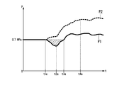
図2に示すチリングユニット1が行う冷却サイクルの運転を説明する図は、冷媒が図1で示した実線の矢印の方向にチリングユニット1の内部を流れたときの時刻と冷媒の圧力との関係を示している。図2において、横軸は時刻である。また、縦軸は冷媒の圧力である。
圧力P1は、第一の圧力センサ202が検出する冷媒の圧力である。また、圧力P2は、第二の圧力センサ203が検出する冷媒の圧力である。
時刻0は、基準となる時刻である。時刻0では、コンプレッサ209は動作していない。時刻0では、チリングユニット1における冷媒は、平衡状態となっている。なお、図2の場合、時刻0における圧力P1と圧力P2のそれぞれは、0.7MPaである。時刻t1aは、コンプレッサ209が動作を開始する時刻である。時刻t2aは、圧力P1が最小となる時刻である。時刻t3aは、圧力P1が時刻0における圧力である0.7MPaに戻る時刻である。時刻t4aは、コンプレッサ209の動作時に、チリングユニット1における冷媒が平衡状態となる時刻である。以下で、各時刻におけるチリングユニット1の動作を説明する。
時刻0から時刻t1aまでの間は、コンプレッサ209は動作していない。時刻0から時刻t1aまでの間は、チリングユニット1における冷媒は平衡状態である。時刻t1aにコンプレッサ209が動作を開始すると、コンプレッサ209は、冷媒を入力する。コンプレッサ209は、冷媒を入力時の冷媒よりも高温で高圧の冷媒にし、四方弁207を介して空気熱交換器101に送出する。このとき、冷媒は、四方弁207と空気熱交換器101の間の冷媒管に設けられた第二の圧力センサ203を通過する。そのため、第二の圧力センサ203が検出する冷媒の圧力P2は、時刻t1aから徐々に上昇する。
凝縮器として機能する空気熱交換器101は、第二の圧力センサ203を通過した冷媒を入力する。空気熱交換器101は、入力した冷媒を外気と熱交換させ、入力時よりも低温の冷媒にする。空気熱交換器101は、冷媒を膨張弁215に送出する。
膨張弁215は、入力した冷媒を減圧調整と流量調整を行ってさらに低温で低圧の冷媒にし、水熱交換器201に送出する。このときの冷媒の温度は、水熱交換器201における水及び外気の温度よりも低温である。
蒸発器として機能する水熱交換器201は、膨張弁215から冷媒を入力する。空気熱交換器101は、入力した冷媒を水及び外気と熱交換させる。水熱交換器201が入力した冷媒の温度は、水熱交換器201における水及び外気の温度よりも低温である。そのため、冷媒は温度と圧力が上昇し、水は冷却される。水熱交換器201は、冷媒を四方弁207を介してアキュムレータ208に送出する。このとき、冷媒は、水熱交換器201と四方弁207の間の冷媒管に設けられた第一の圧力センサ202を通過する。時刻t1aにコンプレッサ209が運転を開始した直後は、チリングユニット1において第二の圧力センサ203が検出する冷媒の圧力から第一の圧力センサ202が検出する冷媒の圧力を減じることにより得られる差圧が小さい。そのため、チリングユニット1内を循環する冷媒の単位時間当たりの流量は少量である。循環する冷媒の単位時間当たりの流量が少量である場合、コンプレッサ209が圧縮する冷媒の量も少量となり、コンプレッサ209が冷媒を圧縮する圧縮率は低い。そのため、コンプレッサ209が冷媒を加熱させる温度は、空気熱交換器101と膨張弁215が減圧調整と流量調整を行って冷媒を冷却させる温度よりも低く、第一の圧力センサ202が検出する冷媒の圧力P1は、時刻t1aから徐々に低下する。
アキュムレータ208は、蒸発器でガス化しきれなかった冷媒が液状のままコンプレッサ209に吸入されるのを防止する。これにより、アキュムレータ208は、ガス冷媒のみをコンプレッサモータ210を介してコンプレッサ209に送出する。
このような冷却サイクルの運転を続けると、チリングユニット1内を循環する冷媒の単位時間当たりの流量が増加し、コンプレッサ209が冷媒を圧縮し加熱する温度が上昇する。そのため、コンプレッサ209が四方弁207を介して空気熱交換器101に送出する冷媒の温度は上昇する。時刻t2aにおいて、コンプレッサ209が冷媒を加熱させる温度は、空気熱交換器101と膨張弁215が冷媒を冷却させる温度よりも高くなる。そのため、水熱交換器201と四方弁207の間の冷媒管における冷媒の温度が上昇し、第一の圧力センサ202が検出する冷媒の圧力P1が上昇する。
その後、第一の圧力センサ202が検出する冷媒の圧力P1と、第二の圧力センサ203が検出する冷媒の圧力P2のそれぞれは、過渡的に上昇する。第一の圧力センサ202が検出する冷媒の圧力P1は、時刻t3aに時刻0における圧力と同一の0.7MPaとなり上昇を続ける。
第一の圧力センサ202が検出する冷媒の圧力P1と、第二の圧力センサ203が検出する冷媒の圧力P2のそれぞれは、時刻t4aに冷却サイクルの運転に対して設計された定常状態となる。
第一の圧力センサ202が検出する冷媒の圧力P1と、第二の圧力センサ203が検出する冷媒の圧力P2のそれぞれは、時刻t4aに冷却サイクルの運転に対して設計された定常状態となる。
蒸発器として機能する水熱交換器201が膨張弁215から冷媒を入力し、冷媒を水及び外気と熱交換させて水を冷却する際、外気温が水の凝固点をわずかに上回る程度の低温である場合、水熱交換器201における熱交換により水が凍結する可能性がある。つまり、チリングユニット1において、制御部217が加熱サイクルの運転をさせる制御を行わずに、水熱交換器201により水を冷却する冷却サイクルの運転をさせる制御を直ちに行った場合、冷却対象である水が凍結してしまう可能性がある。
冬などの外気温が低い時期にチリングユニット1において、制御部217が冷却サイクルの運転を開始する前に、加熱サイクルの運転をさせ、第二の圧力センサ203が検出する冷媒の圧力から第一の圧力センサ202が検出する冷媒の圧力(P2>P1)を減じることにより得られる差圧が所定の差圧以上の状態に制御する場合について説明する。
チリングユニット1において、制御部217が加熱サイクルの運転をさせる制御を行う場合、上述のように、コンプレッサ209は、入力したガス冷媒を入力時よりも高温で高圧のガス冷媒にして四方弁207を介して水熱交換器201に送出する。凝縮器として機能する水熱交換器201は、冷媒を水と熱交換させる。このとき、冷媒の温度は水温よりも高い。そのため、水熱交換器201は、入力した冷媒を入力時よりも低温の冷媒にして膨張弁215に送出する。膨張弁215は、入力した冷媒を減圧調整と流量調整を行ってさらに低温で低圧の冷媒にして空気熱交換器101に送出する。蒸発器として機能する空気熱交換器101は、膨張弁215から入力した冷媒を外気と熱交換させる。このとき、冷媒の温度は、外気温度よりも低い。そのため、空気熱交換器101は、冷媒の温度を上昇させる。そして、空気熱交換器101は、冷媒を四方弁207を介してアキュムレータ208に送出する。アキュムレータ208は、蒸発器でガス化しきれなかった冷媒が液状のままコンプレッサ209に吸入されるのを防止する。これにより、アキュムレータ208は、ガス冷媒のみをコンプレッサモータ210を介してコンプレッサ209に送出する。その結果、冷媒は、図1に示す点線の矢印の方向にチリングユニット1の内部を流れる。
その後、制御部217は、加熱サイクルの運転をさせる制御から冷却サイクルの運転をさせる制御に切り替える。その結果、冷媒は、図1に示す実線の矢印の方向にチリングユニット1の内部を流れる。
その後、制御部217は、加熱サイクルの運転をさせる制御から冷却サイクルの運転をさせる制御に切り替える。その結果、冷媒は、図1に示す実線の矢印の方向にチリングユニット1の内部を流れる。
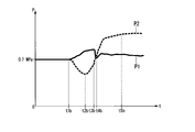
図3に示すチリングユニット1が冷却サイクルの運転を開始する前に行う加熱サイクルの運転を説明する図は、冷媒が図1に示す実線の矢印の方向にチリングユニット1の内部を流れたときの時刻と冷媒の圧力との関係を示している。
図3において、横軸は時刻である。また、縦軸は冷媒の圧力である。
圧力P1は、第一の圧力センサ202が検出する冷媒の圧力である。圧力P2は、第二の圧力センサ203が検出する冷媒の圧力である。
時刻0は、基準となる時刻である。時刻0では、コンプレッサ209は動作していない。時刻0では、チリングユニット1における冷媒は、平衡状態となっている。なお、図3の場合、時刻0における圧力P1と圧力P2のそれぞれは、0.7MPaである。時刻t1bは、コンプレッサ209が動作を開始する時刻である。時刻t2bは、第二の圧力センサ203が検出する冷媒の圧力P2から第一の圧力センサ202が検出する冷媒の圧力P1を減じることにより得られる差圧が最大となる時刻である。時刻t3bにおける第二の圧力センサ203が検出する冷媒の圧力P2から第一の圧力センサ202が検出する冷媒の圧力P1を減じることにより得られる差圧は、時刻t2bにおいて圧力P2と圧力P1の差圧が最大となった以降、冷媒がチリングユニット1内を循環しかつ冷却対象である水が凍結しない所定範囲の差圧(例えば、0.3~0.6MPa)となったことを示す差圧の一例である。本発明の一実施形態では、時刻t3bが、制御部217が加熱サイクルの運転をさせる制御から冷却サイクルの運転をさせる制御に切り替える時刻である。時刻t4bは、圧力P1と圧力P2が一致する時刻である。時刻t5bは、コンプレッサ209の動作時に、チリングユニット1における冷媒が平衡状態となる時刻である。以下で、各時刻におけるチリングユニット1の動作を説明する。
時刻0から時刻t1bまでの間、コンプレッサ209は動作していない。時刻0から時刻t1bまでの間、チリングユニット1における冷媒は平衡状態である。時刻t1bにコンプレッサ209が動作を開始すると、コンプレッサ209は、冷媒を入力する。コンプレッサ209は、入力した冷媒を入力時の冷媒よりも高温で高圧の冷媒にし、四方弁207を介して水熱交換器201に送出する。このとき、冷媒は、四方弁207と水熱交換器201の間の冷媒管に設けられた第一の圧力センサ202を通過する。そのため、第一の圧力センサ202が検出する冷媒の圧力P1は、時刻t1bから徐々に上昇する。
凝縮器として機能する水熱交換器201は、第一の圧力センサ202を通過した冷媒を入力する。水熱交換器201は、入力した冷媒を水及び外気と熱交換させ、入力時よりも低温の冷媒にする。このとき、水の温度は上昇する。水熱交換器201は、冷媒を膨張弁215に送出する。
膨張弁215は、入力した冷媒を減圧調整と流量調整を行ってさらに低温で低圧の冷媒にし、空気熱交換器101に送出する。このときの冷媒の温度は、空気熱交換器101における外気の温度よりも低温である。
蒸発器として機能する空気熱交換器101は、膨張弁215から冷媒を入力する。空気熱交換器101は、入力した冷媒を外気と熱交換させる。空気熱交換器101が入力した冷媒の温度は、空気熱交換器101における外気の温度よりも低温である。そのため、冷媒は温度と圧力が上昇する。空気熱交換器101は、冷媒を四方弁207を介してアキュムレータ208に送出する。このとき、冷媒は、空気熱交換器101と四方弁207の間の冷媒管に設けられた第二の圧力センサ203を通過する。そのため、第二の圧力センサ203が検出する冷媒の圧力P2は、時刻t1bから徐々に低下する。
アキュムレータ208は、蒸発器でガス化しきれなかった冷媒が液状のままコンプレッサ209に吸入されるのを防止する。これにより、アキュムレータ208は、ガス冷媒のみをコンプレッサモータ210を介してコンプレッサ209に送出する。
このような冷却サイクルの運転を続けると、コンプレッサ209が四方弁207を介して水熱交換器201に送出する冷媒の温度は上昇する。時刻t2bになるまで、第一の圧力センサ202が検出する冷媒の圧力P1は上昇し、第二の圧力センサ203が検出する冷媒の圧力P2は低下する。時刻t2bになると、第二の圧力センサ203が検出する冷媒の圧力P2から第一の圧力センサ202が検出する冷媒の圧力P1を減じることにより得られる差圧が最大となる。時刻t2bに、コンプレッサ209が四方弁207を介して水熱交換器201に送出する冷媒の温度上昇は水熱交換器201や膨張弁215により冷却される冷媒の温度の低下よりも大きくなる。空気熱交換器101と四方弁207の間の冷媒管における冷媒の温度は上昇し、第二の圧力センサ203が検出する冷媒の圧力P2は上昇する。
その後、第一の圧力センサ202が検出する冷媒の圧力P1と、第二の圧力センサ203が検出する冷媒の圧力P2のそれぞれは、上昇する。圧力P2と圧力P1の差圧が最大となった以降、冷媒がチリングユニット1内を循環しかつ冷却対象である水が凍結しない所定範囲の差圧となった時刻t3bに、制御部217は加熱サイクルの運転をさせる制御から冷却サイクルの運転をさせる制御に切り替える。なお、第二の圧力センサ203が検出する冷媒の圧力P2から第一の圧力センサ202が検出する冷媒の圧力P1を減じることにより得られる差圧が冷媒がチリングユニット1内を循環しかつ冷却対象である水が凍結しない所定の差圧以上の状態であれば、制御部217は加熱サイクルの運転をさせる制御から冷却サイクルの運転をさせる制御に切り替えてよい。
制御部217が加熱サイクルの運転をさせる制御から冷却サイクルの運転をさせる制御に切り替えると、空気熱交換器101と四方弁207の間の冷媒管がコンプレッサ209の出力につながり、水熱交換器201と四方弁207の間の冷媒管がアキュムレータ208とコンプレッサモータ210とを介してコンプレッサ209の入力につながる。
コンプレッサ209は、アキュムレータ208とコンプレッサモータ210とを介して水熱交換器201と四方弁207の間の冷媒管から冷媒を入力する。コンプレッサ209は、入力した冷媒を入力時の冷媒よりも高温で高圧の冷媒にし、四方弁207を介して空気熱交換器101に送出する。このとき、冷媒は、四方弁207と空気熱交換器101の間の冷媒管に設けられた第二の圧力センサ203を通過する。そのため、第二の圧力センサ203が検出する冷媒の圧力P2は上昇する。
凝縮器として機能する空気熱交換器101は、第二の圧力センサ203を通過した冷媒を入力する。空気熱交換器101は、入力した冷媒を外気と熱交換させ、入力時よりも低温の冷媒にする。空気熱交換器101は、冷媒を膨張弁215に送出する。
膨張弁215は、入力した冷媒を減圧調整と流量調整を行ってさらに低温で低圧の冷媒にし、水熱交換器201に送出する。このときの冷媒の温度は、水熱交換器201における水及び外気の温度よりも低温である。
蒸発器として機能する水熱交換器201は、膨張弁215から冷媒を入力する。水熱交換器201は、入力した冷媒を水及び外気と熱交換させる。水熱交換器201が入力した冷媒の温度は、水熱交換器201における水及び外気の温度よりも低温である。そのため、冷媒は温度と圧力が上昇し、水は冷却される。水熱交換器201は、冷媒を四方弁207を介してアキュムレータ208に送出する。このとき、冷媒は、水熱交換器201と四方弁207の間の冷媒管に設けられた第一の圧力センサ202を通過する。そのため、第一の圧力センサ202が検出する冷媒の圧力P1は、時刻t3bから低下する。
アキュムレータ208は、蒸発器でガス化しきれなかった冷媒が液状のままコンプレッサ209に吸入されるのを防止する。これにより、アキュムレータ208は、ガス冷媒のみをコンプレッサモータ210を介してコンプレッサ209に送出する。
このような冷却サイクルの運転を続けると、コンプレッサ209が四方弁207を介して空気熱交換器101に送出する冷媒の温度が上昇する。時刻t4bに第一の圧力センサ202が検出する冷媒の圧力P1と第二の圧力センサ203が検出する冷媒の圧力P2とが一致する。
その後、第一の圧力センサ202が検出する冷媒の圧力P1と、第二の圧力センサ203が検出する冷媒の圧力P2のそれぞれは、上昇する。
第一の圧力センサ202が検出する冷媒の圧力P1と、第二の圧力センサ203が検出する冷媒の圧力P2のそれぞれは、時刻t5bにほぼ平衡状態となる。
したがって、冬などの外気温が低い時期にチリングユニット1において、制御部217が冷却サイクルの運転を開始する前に、加熱サイクルの運転をさせ、第二の圧力センサ203が検出する冷媒の圧力から第一の圧力センサ202が検出する冷媒の圧力を減じることにより得られる差圧が所定の差圧以上の状態に制御する場合には、冷却対象の水が凍結するのを防止することができる。
第一の圧力センサ202が検出する冷媒の圧力P1と、第二の圧力センサ203が検出する冷媒の圧力P2のそれぞれは、時刻t5bにほぼ平衡状態となる。
したがって、冬などの外気温が低い時期にチリングユニット1において、制御部217が冷却サイクルの運転を開始する前に、加熱サイクルの運転をさせ、第二の圧力センサ203が検出する冷媒の圧力から第一の圧力センサ202が検出する冷媒の圧力を減じることにより得られる差圧が所定の差圧以上の状態に制御する場合には、冷却対象の水が凍結するのを防止することができる。
以上、本発明の一実施形態による制御装置216の処理について説明した。本発明の一実施形態による制御装置216の処理によれば、制御部217は、冷却サイクルの運転を開始し水を冷却すると水が凝固点以下の温度となる外気温度である場合、水熱交換器201を用いて水を冷却する冷却サイクルの運転を開始する前に、冷却サイクルの逆サイクルである加熱サイクルの運転をさせる。制御部217は、冷却サイクルの運転をさせる際に、コンプレッサ209と空気熱交換器101との間の冷媒管における冷媒の圧力P2から冷媒の圧力P2よりも低いコンプレッサ209と水熱交換器201との間の冷媒管における冷媒の圧力P1を減じることにより得られる差圧を、冷媒が循環しかつ前記水が凍結しない所定の差圧以上の状態に制御する。具体的には、制御部217は、第二の圧力センサ203が検出する冷媒の圧力から第一の圧力センサ202が検出する冷媒の圧力を減じることにより得られる差圧が、チリングユニット1が平衡状態に至った場合の冷媒の循環流量と同程度の循環流量の冷媒を流すことができる所定範囲の差圧となるタイミングに、冷却サイクルの逆サイクルの運転から冷却サイクルの運転に切り替える。
このようにすれば、制御装置216は、チリングユニット1において、特別な機能を追加することなく、冷却サイクルの運転を開始する時に冷却する水が凍結するのを防止することができる。
なお、チリングユニット1が空気熱交換器101、水熱交換器201及びコンプレッサ209を複数組備える場合、制御部217は、複数組のそれぞれに対して異なるタイミングで、加熱サイクルの運転から冷却サイクルの運転に切り替える制御を行う。
このようにすれば、制御装置216は、チリングユニット1において、加熱サイクルの運転を2組以降の空気熱交換器101、水熱交換器201及びコンプレッサ209に対して行う場合に冷却対象である水の温度上昇を緩和できるため、加熱サイクルの運転を複数組の空気熱交換器101、水熱交換器201及びコンプレッサ209に対して同時に行う場合に比べ、最終的な水の温度上昇を抑えることができる。
なお、制御部217は、第二の圧力センサ203が検出する冷媒の圧力から第一の圧力センサ202が検出する冷媒の圧力を減じることにより得られる差圧が所定の差圧よりも低い場合に、デフロスト制御を行うものであってもよい。
このようにすれば、制御装置216は、チリングユニット1において、特別な機能を追加することなく、冷却サイクルの運転を開始する時に冷却する水が凍結するのを防止することができる。
このようにすれば、制御装置216は、チリングユニット1において、特別な機能を追加することなく、冷却サイクルの運転を開始する時に冷却する水が凍結するのを防止することができる。
なお、チリングユニット1が空気熱交換器101、水熱交換器201及びコンプレッサ209を複数組備える場合、制御部217は、複数組のそれぞれに対して異なるタイミングで、加熱サイクルの運転から冷却サイクルの運転に切り替える制御を行う。
このようにすれば、制御装置216は、チリングユニット1において、加熱サイクルの運転を2組以降の空気熱交換器101、水熱交換器201及びコンプレッサ209に対して行う場合に冷却対象である水の温度上昇を緩和できるため、加熱サイクルの運転を複数組の空気熱交換器101、水熱交換器201及びコンプレッサ209に対して同時に行う場合に比べ、最終的な水の温度上昇を抑えることができる。
なお、制御部217は、第二の圧力センサ203が検出する冷媒の圧力から第一の圧力センサ202が検出する冷媒の圧力を減じることにより得られる差圧が所定の差圧よりも低い場合に、デフロスト制御を行うものであってもよい。
このようにすれば、制御装置216は、チリングユニット1において、特別な機能を追加することなく、冷却サイクルの運転を開始する時に冷却する水が凍結するのを防止することができる。
本発明の実施形態について説明したが、上述の制御装置216は内部に、コンピュータシステムを有している。そして、上述した処理の過程は、プログラムの形式でコンピュータ読み取り可能な記録媒体に記憶されており、このプログラムをコンピュータが読み出して実行することによって、上記処理が行われる。ここでコンピュータ読み取り可能な記録媒体とは、磁気ディスク、光磁気ディスク、CD-ROM、DVD-ROM、半導体メモリ等をいう。また、このコンピュータプログラムを通信回線によってコンピュータに配信し、この配信を受けたコンピュータがそのプログラムを実行するようにしてもよい。
また、上記プログラムは、前述した機能の一部を実現してもよい。さらに、上記プログラムは、前述した機能をコンピュータシステムにすでに記録されているプログラムとの組み合わせで実現できるファイル、いわゆる差分ファイル(差分プログラム)であってもよい。
本発明のいくつかの実施形態を説明したが、これらの実施形態は、例であり、発明の範囲を限定しない。これらの実施形態は、発明の要旨を逸脱しない範囲で、種々の省略、置き換え、変更を行ってよい。
本発明の実施形態による制御装置によれば、チリングユニットにおいて、冷却サイクルの運転を開始する時に冷却する水が凍結するのを防止することができる。
1 チリングユニット
101 空気熱交換器
201 水熱交換器
202 第一の圧力センサ
203 第二の圧力センサ
207 四方弁
208 アキュムレータ
209 コンプレッサ
210 コンプレッサモータ
215 膨張弁
216 制御装置
217 制御部
101 空気熱交換器
201 水熱交換器
202 第一の圧力センサ
203 第二の圧力センサ
207 四方弁
208 アキュムレータ
209 コンプレッサ
210 コンプレッサモータ
215 膨張弁
216 制御装置
217 制御部
Claims (5)
- 外気と熱交換した冷媒を送出する空気熱交換器と、前記空気熱交換器から送出された冷媒と水とを熱交換させて前記水を冷却する水熱交換器と、前記冷媒を圧縮し前記圧縮された冷媒を送出するコンプレッサと、前記コンプレッサから送出された冷媒を前記空気熱交換器に送出する第1冷媒管と、を備えるチリングユニットのための制御装置であって、
前記水熱交換器を用いて前記水を冷却する冷却サイクルの運転をさせるときに、前記第1冷媒管における冷媒の圧力から前記コンプレッサと前記水熱交換器との間の第2冷媒管における冷媒の圧力を減じることにより得られる差圧を、前記冷媒が循環しかつ前記水が凍結しない所定の差圧以上の状態に制御し、外気温度が前記水を凝固点以下の温度とする外気温度であるとき、前記チリングユニットに前記冷却サイクルの運転を開始させる前に、前記チリングユニットに前記冷却サイクルの逆サイクルの運転をさせる制御部、
を備える制御装置。 - 前記第2冷媒管における冷媒の圧力を検出する第一の圧力センサと、
前記第1冷媒管における冷媒の圧力を検出する第二の圧力センサと、
を備え、
前記制御部は、
前記第二の圧力センサが検出する冷媒の圧力から前記第一の圧力センサが検出する冷媒の圧力を減じることにより得られる差圧が、前記チリングユニットが平衡状態に至った場合の前記冷媒の循環流量と同程度の循環流量の前記冷媒を流すことができる所定範囲の前記差圧となるタイミングに、前記冷却サイクルの逆サイクルの運転から前記冷却サイクルの運転に切り替える、
請求項1に記載の制御装置。 - 前記チリングユニットが空気熱交換器、水熱交換器及びコンプレッサを複数組備える場合、
前記制御部は、前記複数組のそれぞれに対して異なるタイミングで前記冷却サイクルの逆サイクルの運転から前記冷却サイクルの運転に切り替える、
請求項2に記載の制御装置。 - 外気と熱交換した冷媒を送出する空気熱交換器と、前記空気熱交換器から送出された冷媒と水とを熱交換させて前記水を冷却する水熱交換器と、前記冷媒を圧縮し前記圧縮された冷媒を送出するコンプレッサと、前記コンプレッサから送出された冷媒を前記空気熱交換器に送出する第1冷媒管と、を備えるチリングユニットのための制御装置の制御方法であって、
前記水熱交換器を用いて前記水を冷却する冷却サイクルの運転をさせるときに、前記コンプレッサと前記空気熱交換器との間の冷媒管における冷媒の圧力から前記コンプレッサと前記水熱交換器との間の冷媒管における冷媒の圧力を減じることにより得られる差圧を、前記冷媒が循環しかつ前記水が凍結しない所定の差圧以上の状態に制御し、外機温度が前記水を凝固点以下の温度とする外気温度であるとき、前記チリングユニットに前記冷却サイクルの運転を開始させる前に、前記チリングユニットに前記冷却サイクルの逆サイクルの運転をさせること、
を含む制御方法。 - 外気と熱交換した冷媒を送出する空気熱交換器と、前記空気熱交換器から送出された冷媒と水とを熱交換させて前記水を冷却する前記水熱交換器と、前記冷媒を圧縮し前記圧縮された冷媒を送出するコンプレッサと、前記コンプレッサから送出された冷媒を前記空気熱交換器に送出する第1冷媒管と、を備えるチリングユニットのためのコンピュータに、
前記水熱交換器を用いて前記水を冷却する冷却サイクルの運転をさせるときに、前記コンプレッサと前記空気熱交換器との間の冷媒管における冷媒の圧力から前記コンプレッサと前記水熱交換器との間の冷媒管における冷媒の圧力を減じることにより得られる差圧を、前記冷媒が循環しかつ前記水が凍結しない所定の差圧以上の状態に制御し、外気温度が前記水を凝固点以下の温度とする外気温度であるとき、前記チリングユニットに前記冷却サイクルの運転を開始させる前に、前記チリングユニットに前記冷却サイクルの逆サイクルの運転をさせること、
を実行させるプログラム。
Priority Applications (4)
| Application Number | Priority Date | Filing Date | Title |
|---|---|---|---|
| EP16746478.3A EP3249321B1 (en) | 2015-02-02 | 2016-01-27 | Control device, control method, and program |
| CN201680007793.7A CN107208942A (zh) | 2015-02-02 | 2016-01-27 | 控制装置、控制方法以及程序 |
| KR1020177020977A KR101980467B1 (ko) | 2015-02-02 | 2016-01-27 | 제어 장치, 제어 방법 및 프로그램 |
| ES16746478T ES2717312T3 (es) | 2015-02-02 | 2016-01-27 | Dispositivo de control, método de control y programa |
Applications Claiming Priority (2)
| Application Number | Priority Date | Filing Date | Title |
|---|---|---|---|
| JP2015018384A JP6501392B2 (ja) | 2015-02-02 | 2015-02-02 | 制御装置、制御方法及びプログラム |
| JP2015-018384 | 2015-02-02 |
Publications (1)
| Publication Number | Publication Date |
|---|---|
| WO2016125647A1 true WO2016125647A1 (ja) | 2016-08-11 |
Family
ID=56563996
Family Applications (1)
| Application Number | Title | Priority Date | Filing Date |
|---|---|---|---|
| PCT/JP2016/052273 Ceased WO2016125647A1 (ja) | 2015-02-02 | 2016-01-27 | 制御装置、制御方法及びプログラム |
Country Status (6)
| Country | Link |
|---|---|
| EP (1) | EP3249321B1 (ja) |
| JP (1) | JP6501392B2 (ja) |
| KR (1) | KR101980467B1 (ja) |
| CN (1) | CN107208942A (ja) |
| ES (1) | ES2717312T3 (ja) |
| WO (1) | WO2016125647A1 (ja) |
Families Citing this family (1)
| Publication number | Priority date | Publication date | Assignee | Title |
|---|---|---|---|---|
| CN116294410A (zh) * | 2023-02-13 | 2023-06-23 | 合肥华凌股份有限公司 | 冰箱的商检系统及其检测方法、控制器和存储介质 |
Citations (5)
| Publication number | Priority date | Publication date | Assignee | Title |
|---|---|---|---|---|
| JP2005300056A (ja) * | 2004-04-14 | 2005-10-27 | Matsushita Electric Ind Co Ltd | 冷凍サイクル装置 |
| JP2005351494A (ja) * | 2004-06-08 | 2005-12-22 | Daikin Ind Ltd | 冷凍装置 |
| JP2007170706A (ja) * | 2005-12-20 | 2007-07-05 | Sanyo Electric Co Ltd | 冷凍システム |
| JP2009174769A (ja) * | 2008-01-24 | 2009-08-06 | Miura Co Ltd | チラー |
| JP2011257108A (ja) * | 2010-06-11 | 2011-12-22 | Mitsubishi Electric Corp | 冷凍空調装置 |
Family Cites Families (5)
| Publication number | Priority date | Publication date | Assignee | Title |
|---|---|---|---|---|
| JPS63129258A (ja) | 1986-11-19 | 1988-06-01 | 三洋電機株式会社 | ヒ−トポンプ式空気調和機 |
| JP4974714B2 (ja) * | 2007-03-09 | 2012-07-11 | 三菱電機株式会社 | 給湯器 |
| JP2014052123A (ja) * | 2012-09-06 | 2014-03-20 | Yanmar Co Ltd | エンジン駆動ヒートポンプチラー |
| CN104813121B (zh) * | 2012-12-11 | 2016-08-24 | 三菱电机株式会社 | 空调供热水复合系统 |
| ES2710923T3 (es) * | 2012-12-26 | 2019-04-29 | Daikin Ind Ltd | Calentador de agua caliente con bomba de calor |
-
2015
- 2015-02-02 JP JP2015018384A patent/JP6501392B2/ja active Active
-
2016
- 2016-01-27 WO PCT/JP2016/052273 patent/WO2016125647A1/ja not_active Ceased
- 2016-01-27 KR KR1020177020977A patent/KR101980467B1/ko active Active
- 2016-01-27 CN CN201680007793.7A patent/CN107208942A/zh active Pending
- 2016-01-27 ES ES16746478T patent/ES2717312T3/es active Active
- 2016-01-27 EP EP16746478.3A patent/EP3249321B1/en active Active
Patent Citations (5)
| Publication number | Priority date | Publication date | Assignee | Title |
|---|---|---|---|---|
| JP2005300056A (ja) * | 2004-04-14 | 2005-10-27 | Matsushita Electric Ind Co Ltd | 冷凍サイクル装置 |
| JP2005351494A (ja) * | 2004-06-08 | 2005-12-22 | Daikin Ind Ltd | 冷凍装置 |
| JP2007170706A (ja) * | 2005-12-20 | 2007-07-05 | Sanyo Electric Co Ltd | 冷凍システム |
| JP2009174769A (ja) * | 2008-01-24 | 2009-08-06 | Miura Co Ltd | チラー |
| JP2011257108A (ja) * | 2010-06-11 | 2011-12-22 | Mitsubishi Electric Corp | 冷凍空調装置 |
Also Published As
| Publication number | Publication date |
|---|---|
| JP2016142452A (ja) | 2016-08-08 |
| ES2717312T3 (es) | 2019-06-20 |
| CN107208942A (zh) | 2017-09-26 |
| JP6501392B2 (ja) | 2019-04-17 |
| KR101980467B1 (ko) | 2019-05-20 |
| KR20170100019A (ko) | 2017-09-01 |
| EP3249321A4 (en) | 2017-12-27 |
| EP3249321B1 (en) | 2019-01-23 |
| EP3249321A1 (en) | 2017-11-29 |
Similar Documents
| Publication | Publication Date | Title |
|---|---|---|
| CN101918776B (zh) | 控制运行于自由冷却模式下的空调系统的方法和系统 | |
| JP5875649B2 (ja) | 空気調和機 | |
| CN108136876B (zh) | 车辆用温度调整装置 | |
| JP2015168297A5 (ja) | ||
| WO2020064014A1 (zh) | 车辆温度管理系统 | |
| WO2016132466A1 (ja) | 空気調和システム | |
| JP6231395B2 (ja) | 複合熱源ヒートポンプ装置 | |
| WO2014112615A1 (ja) | 二元冷凍サイクル装置 | |
| JPWO2016016918A1 (ja) | 空気調和装置 | |
| JPWO2019058450A1 (ja) | 冷凍機 | |
| JPWO2016088262A1 (ja) | 冷凍サイクル装置 | |
| JP5113776B2 (ja) | 冷凍装置 | |
| JP2008241065A (ja) | 冷凍装置及び冷凍装置の油戻し方法 | |
| JP2015161467A (ja) | 複合熱源ヒートポンプ装置 | |
| JP2017047888A5 (ja) | ||
| JP2017150791A (ja) | 複合熱源ヒートポンプ装置 | |
| JP6501392B2 (ja) | 制御装置、制御方法及びプログラム | |
| JP6599812B2 (ja) | 複合熱源ヒートポンプ装置 | |
| JP2012515890A (ja) | 冷凍サイクル装置 | |
| JP2015117899A (ja) | ヒートポンプ装置 | |
| JP6398548B2 (ja) | 車両用空調装置 | |
| JP6830296B2 (ja) | 複合熱源ヒートポンプ装置 | |
| JP6208086B2 (ja) | 複合熱源ヒートポンプ装置 | |
| JP7041024B2 (ja) | 複合熱源ヒートポンプ装置 | |
| JP2017138049A (ja) | ヒートポンプ装置 |
Legal Events
| Date | Code | Title | Description |
|---|---|---|---|
| 121 | Ep: the epo has been informed by wipo that ep was designated in this application |
Ref document number: 16746478 Country of ref document: EP Kind code of ref document: A1 |
|
| ENP | Entry into the national phase |
Ref document number: 20177020977 Country of ref document: KR Kind code of ref document: A |
|
| REEP | Request for entry into the european phase |
Ref document number: 2016746478 Country of ref document: EP |
|
| NENP | Non-entry into the national phase |
Ref country code: DE |