WO2016125880A1 - 配線シート、構造体および光発電モジュール - Google Patents
配線シート、構造体および光発電モジュール Download PDFInfo
- Publication number
- WO2016125880A1 WO2016125880A1 PCT/JP2016/053461 JP2016053461W WO2016125880A1 WO 2016125880 A1 WO2016125880 A1 WO 2016125880A1 JP 2016053461 W JP2016053461 W JP 2016053461W WO 2016125880 A1 WO2016125880 A1 WO 2016125880A1
- Authority
- WO
- WIPO (PCT)
- Prior art keywords
- copolymer
- ethylene
- sheet
- resin
- wiring
- Prior art date
- Legal status (The legal status is an assumption and is not a legal conclusion. Google has not performed a legal analysis and makes no representation as to the accuracy of the status listed.)
- Ceased
Links
Images


Classifications
-
- H—ELECTRICITY
- H10—SEMICONDUCTOR DEVICES; ELECTRIC SOLID-STATE DEVICES NOT OTHERWISE PROVIDED FOR
- H10F—INORGANIC SEMICONDUCTOR DEVICES SENSITIVE TO INFRARED RADIATION, LIGHT, ELECTROMAGNETIC RADIATION OF SHORTER WAVELENGTH OR CORPUSCULAR RADIATION
- H10F19/00—Integrated devices, or assemblies of multiple devices, comprising at least one photovoltaic cell covered by group H10F10/00, e.g. photovoltaic modules
- H10F19/90—Structures for connecting between photovoltaic cells, e.g. interconnections or insulating spacers
-
- H—ELECTRICITY
- H10—SEMICONDUCTOR DEVICES; ELECTRIC SOLID-STATE DEVICES NOT OTHERWISE PROVIDED FOR
- H10F—INORGANIC SEMICONDUCTOR DEVICES SENSITIVE TO INFRARED RADIATION, LIGHT, ELECTROMAGNETIC RADIATION OF SHORTER WAVELENGTH OR CORPUSCULAR RADIATION
- H10F19/00—Integrated devices, or assemblies of multiple devices, comprising at least one photovoltaic cell covered by group H10F10/00, e.g. photovoltaic modules
- H10F19/80—Encapsulations or containers for integrated devices, or assemblies of multiple devices, having photovoltaic cells
-
- H—ELECTRICITY
- H10—SEMICONDUCTOR DEVICES; ELECTRIC SOLID-STATE DEVICES NOT OTHERWISE PROVIDED FOR
- H10F—INORGANIC SEMICONDUCTOR DEVICES SENSITIVE TO INFRARED RADIATION, LIGHT, ELECTROMAGNETIC RADIATION OF SHORTER WAVELENGTH OR CORPUSCULAR RADIATION
- H10F19/00—Integrated devices, or assemblies of multiple devices, comprising at least one photovoltaic cell covered by group H10F10/00, e.g. photovoltaic modules
- H10F19/80—Encapsulations or containers for integrated devices, or assemblies of multiple devices, having photovoltaic cells
- H10F19/804—Materials of encapsulations
-
- H—ELECTRICITY
- H10—SEMICONDUCTOR DEVICES; ELECTRIC SOLID-STATE DEVICES NOT OTHERWISE PROVIDED FOR
- H10F—INORGANIC SEMICONDUCTOR DEVICES SENSITIVE TO INFRARED RADIATION, LIGHT, ELECTROMAGNETIC RADIATION OF SHORTER WAVELENGTH OR CORPUSCULAR RADIATION
- H10F77/00—Constructional details of devices covered by this subclass
- H10F77/93—Interconnections
-
- Y—GENERAL TAGGING OF NEW TECHNOLOGICAL DEVELOPMENTS; GENERAL TAGGING OF CROSS-SECTIONAL TECHNOLOGIES SPANNING OVER SEVERAL SECTIONS OF THE IPC; TECHNICAL SUBJECTS COVERED BY FORMER USPC CROSS-REFERENCE ART COLLECTIONS [XRACs] AND DIGESTS
- Y02—TECHNOLOGIES OR APPLICATIONS FOR MITIGATION OR ADAPTATION AGAINST CLIMATE CHANGE
- Y02E—REDUCTION OF GREENHOUSE GAS [GHG] EMISSIONS, RELATED TO ENERGY GENERATION, TRANSMISSION OR DISTRIBUTION
- Y02E10/00—Energy generation through renewable energy sources
- Y02E10/50—Photovoltaic [PV] energy
Definitions
- the present invention relates to a wiring sheet, a structure, and a photovoltaic module.
- the photovoltaic module is usually mounted with a semiconductor element (photovoltaic element) that changes light energy into electrical energy.
- a semiconductor element photovoltaic element
- the photovoltaic element in order to prevent the degradation of the power generation characteristics of the module, the photovoltaic element is in contact with the outside air, and the photovoltaic element is prevented from being subjected to an impact.
- the photovoltaic element is sealed with a resin sheet.
- the resin sheet is required to be transparent in order to efficiently supply light energy to the photovoltaic device.
- an ethylene-vinyl acetate copolymer EVA
- Examples of technologies that focus on the structure of the resin sheet include the following.
- Patent Document 1 discloses a resin encapsulated sheet containing an ethylene-vinyl acetate copolymer (EVA) and an ultraviolet absorber and treated with ionizing radiation.
- EVA ethylene-vinyl acetate copolymer
- the conventional resin sheet employs a structure containing an ultraviolet absorber, a certain degree of effect can be expected in terms of long-term durability in which the resin is prevented from being deteriorated by ultraviolet rays.
- the conventional resin sheet employs a configuration that prevents light of a wavelength region of less than 380 nm, that is, ultraviolet light itself, from entering the photovoltaic element in order to realize the long-term durability of the resin sheet. It was. Therefore, it has a limit in improving the power generation efficiency of the photovoltaic module.
- an object of the present invention is to provide a wiring sheet capable of efficiently contributing to the power generation by using light energy derived from ultraviolet rays, a structure including the wiring sheet, and a photovoltaic module.
- the present inventors have been able to use a resin material that can be used for a wiring sheet that does not deteriorate even when irradiated with ultraviolet rays for a long period of time.
- a resin material that can be used for a wiring sheet that does not deteriorate even when irradiated with ultraviolet rays for a long period of time.
- We studied earnestly As a result, the characteristics of the wiring sheet change slightly depending on the combination of various factors such as the type of resin used, the density of the resin, the melt flow rate of the resin, the cross-linking state of the resin, the type and amount of additives. I found out. Therefore, it has been difficult to generalize and define the characteristics of the resin material for forming the wiring sheet according to the present invention.
- the inventors have determined that the light transmittance of the resin sheet at a wavelength of 350 nm is a design guideline. As a result, the present invention was found.
- a structure comprising the above wiring sheet and a sealing material formed of a resin material containing any of the following (A) and (B) is provided.
- a translucent substrate; The wiring sheet; A photovoltaic module is provided.
- a wiring sheet capable of efficiently contributing light energy derived from ultraviolet rays to power generation, a structure including the wiring sheet, and a photovoltaic module.
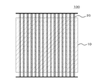
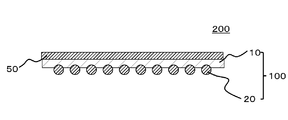
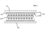
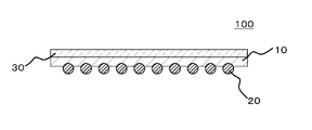
- sectional drawing which shows the wiring sheet which concerns on 1st Embodiment. It is an example of the top view which shows the wiring sheet which concerns on 1st Embodiment. It is an example of a sectional view showing the structure concerning a 1st embodiment. It is an example of sectional drawing which shows the photovoltaic module which concerns on 1st Embodiment. It is an example of sectional drawing which shows the wiring sheet which concerns on 2nd Embodiment. It is an example of typical sectional drawing which shows the layer structure of the photovoltaic module which concerns on 2nd Embodiment.
- FIG. 1 is an example of a cross-sectional view showing a wiring sheet 100 according to the present embodiment.
- a wiring sheet 100 according to this embodiment includes a resin sheet 10 and fine wirings 20 provided on one surface of the resin sheet 10.
- the light transmittance at a wavelength of 350 nm of the resin sheet 10 measured according to JIS-K7105 is 70% or more. By doing so, it is possible to realize the wiring sheet 100 that can efficiently contribute to the power generation by the light energy derived from the ultraviolet rays.
- the light energy derived from ultraviolet rays in the present embodiment refers to light energy derived from light in a wavelength region of less than 380 nm.
- the resin sheet premised on the light receiving surface (incident surface) side of the photovoltaic module used for sealing the photovoltaic element in the photovoltaic module generally has the following six performances. Is required. The first required performance is transparency to transmit more light. Secondly, the required performance is flexibility to prevent the photovoltaic element from breaking. Third, the required performance can realize a state in which the photovoltaic element and the resin sheet are in close contact with each other to the extent that air can enter from the outside of the photovoltaic module and prevent it from coming into contact with the photovoltaic element. Adhesive. Fourthly, the required performance is a tensile strength that can prevent the resin from expanding or contracting due to a temperature change in the usage environment of the photovoltaic module.
- the fifth required performance is weather resistance to such an extent that the resin material can be prevented from being deteriorated by ultraviolet rays.
- the performance required 6th is long-term heat-and-moisture resistance of the grade which can prevent the performance degradation and failure of a photovoltaic device at the time of use of a photovoltaic module.
- the wiring sheet 100 according to the present embodiment employs a configuration in which the resin sheet 10 can transmit light having a wavelength of 350 nm or more over a specific amount. Therefore, according to the wiring sheet 100 which concerns on this embodiment, the optical energy derived from the said ultraviolet-ray can be utilized, without converting the wavelength of the taken-in ultraviolet-ray. Thereby, the photovoltaic module which improved the power generation efficiency compared with the conventional resin sheet is realizable.
- the wiring sheet 100 according to the present embodiment naturally satisfies the six required characteristics described above.
- the light transmittance at a wavelength of 350 nm of the resin sheet 10 measured according to JIS-K7105 is 70% or more, preferably 75% or more, more preferably 80% or more. By doing so, it becomes possible to more effectively contribute light energy derived from ultraviolet rays to power generation.
- the total light transmittance of the resin sheet 10 measured according to JIS-K7105 is preferably 80% or more, and more preferably 85% or more. By doing so, light in various wavelength regions as well as ultraviolet light can be efficiently contributed to power generation.
- white light including ultraviolet light, visible light and infrared light is used.
- ⁇ Fine wiring 20> As shown in FIG. 1, in the wiring sheet 100, a part of the fine wiring 20 is preferably embedded in the resin sheet 10. By doing so, the bonding state between the fine wiring 20 and the resin sheet 10 can be strengthened. Therefore, the influence by the impact applied to the photovoltaic element 400 (refer FIG. 4) in the state sealed using the wiring sheet 100 can be relieved.
- FIG. 2 is an example of a plan view showing the wiring sheet 100 according to the present embodiment.
- the fine wiring 20 in the wiring sheet 100 according to the present embodiment is preferably formed of a plurality of wires arranged in parallel from the viewpoint of reducing the cost of the photovoltaic module. By doing so, it is possible to reduce the amount of the metal material used for forming the fine wiring 20.
- the metal material that forms the fine wiring 20 include silver, copper, indium, and tin. Among these, indium, tin, or an alloy of indium and tin is preferable.
- the wire forming the fine wiring 20 is preferably a wire with a diameter of 50 ⁇ m or more and 500 ⁇ m or less, and more preferably a wire with a diameter of 100 ⁇ m or more and 300 ⁇ m or less from the viewpoint of current collection efficiency.
- the characteristics of the wiring sheet 100 include the type of resin to be used, the density of the resin, the melt flow rate of the resin, the crosslinked state of the resin, and the type of additive.
- the resin sheet 10 in the wiring sheet 100 is (A) a copolymer of ethylene and an unsaturated carboxylic acid, or ethylene and an unsaturated carboxylic acid. And (B) a copolymer containing ethylene and (meth) acrylic acid glycidyl (also referred to as glycidyl (meth) acrylate), and a resin material. It is preferable.
- each of the resin materials described above is a resin having high transparency, is hardly affected by ultraviolet rays, and is excellent in mechanical properties such as tensile strength. Therefore, when the compounding composition of the resin material described above is highly controlled, there is a high possibility of realizing the resin sheet 10 that can efficiently contribute to the power generation of light energy derived from ultraviolet rays. The details of the resin material forming the resin sheet 10 will be described later.
- the resin sheet 10 has a Shore D hardness of a material forming the resin sheet 10 measured preferably with a type D durometer in accordance with JIS-K7125 under a room temperature (25 ° C.) condition, preferably more than 25 and not more than 200. More preferably, it is 30 or more and 200 or less, More preferably, it is 45 or more and 200 or less, More preferably, it is 48 or more and 100 or less.
- the durability of the photovoltaic module can be improved.
- the embedding of the fine wiring 20 in the resin sheet 10 can be appropriately controlled when the fine wiring 20 is formed on the resin sheet 10, the connection with the photovoltaic element 400 is applied when applied to the photovoltaic module. It can be good.
- electric power generation efficiency can further be improved.
- the resin sheet 10 has a storage elastic modulus E ′ at 60 ° C. of the material forming the resin sheet 10 of preferably 1 MPa or more and 1000 MPa or less, more preferably 10 MPa or more and 1000 MPa or less, and further preferably 20 MPa or more and 500 MPa or less. It is. By doing so, in the photovoltaic module, the influence due to the impact applied to the photovoltaic element 400 in the sealed state using the wiring sheet 100 can be mitigated, and further, the burying of the fine wiring 20 can be appropriately performed. Can be adjusted within a wide range. Therefore, according to the wiring sheet 100 including the resin sheet 10 having the storage elastic modulus E ′ measured in a specific region for a specific region within the above numerical range, the durability of the photovoltaic module is improved and the power generation efficiency is increased. Can be improved.
- the resin sheet 10 has a flexural modulus measured according to JIS-K7106 under a room temperature (25 ° C.) condition for the material forming the resin sheet 10, preferably 10 MPa or more and 400 MPa or less, more preferably 30 MPa or more. 400 MPa or less, more preferably 50 MPa or more and 400 MPa or less, and still more preferably 100 MPa or more and 300 MPa or less.
- the resin sheet 10 preferably has a tensile modulus obtained when a tensile test is performed under the conditions of 25 ° C. and a load speed of 200 mm / min, satisfying the following conditions.
- the MD direction of the tensile modulus of the resin sheet 10 obtained when a tensile test was performed under the condition that the load rate of 200 mm / min, and TS M JIS- in accordance with K7127, 25 ° C., when the TD direction of the tensile modulus of the resin sheet 10 obtained when a tensile test was performed under the condition that the load rate of 200 mm / min, and a TS T, the value of TS M / TS T
- it is preferably 0.9 or more and 1.1 or less, and more preferably 0.95 or more and 1.05 or less.
- the resin sheet 10 has a moisture permeability coefficient at 85 ° C. and 90% RH of the resin sheet 10 of preferably 0 g ⁇ mm / m 2 ⁇ day to 100 g ⁇ mm / m 2 ⁇ day, and more preferably 0 g ⁇ mm / m 2 ⁇ day to 70 g ⁇ mm / m 2 ⁇ day.
- the wiring sheet 100 excellent in long-term wet heat resistance can be implement
- the resin sheet 10 is preferably formed of a resin material including any of the following (A) and (B).
- the melt flow rate measured under conditions of 190 ° C. and a load of 2169 g according to JIS-K7210-1999 is preferably 0.1 g / 10 min to 50 g / 10 min. More preferably, it is 0.5 g / 10 min or more and 30 g / 10 min or less, and most preferably 1 g / 10 min or more and 20 g / 10 min or less. By doing so, it becomes possible to improve the workability of the sheet. Therefore, when the photovoltaic module is manufactured, it is possible to realize good adhesiveness while suppressing the protrusion of the resin.
- the unsaturated carboxylic acid component in the ionomer of a copolymer of ethylene and an unsaturated carboxylic acid or a copolymer of ethylene and an unsaturated carboxylic acid includes acrylic acid, methacrylic acid, ethacrylic acid, fumaric acid, maleic acid, maleic acid. Examples thereof include monomethyl acid and maleic anhydride. Among these, (meth) acrylic acid is preferable as the unsaturated carboxylic acid component. Therefore, the ethylene / unsaturated carboxylic acid copolymer is preferably an ethylene / (meth) acrylic acid copolymer.
- the ethylene / unsaturated carboxylic acid copolymer according to the present embodiment is not limited to a binary copolymer of ethylene and unsaturated carboxylic acid, but an ethylene / unsaturated carboxylic acid / unsaturated carboxylic acid ester copolymer. Also included are multicomponent copolymers containing ethylene and unsaturated carboxylic acids. Examples of the unsaturated carboxylic acid ester component in the ethylene / unsaturated carboxylic acid / unsaturated carboxylic acid ester copolymer include alkyl esters having 1 to 20 carbon atoms of various carboxylic acids used as the unsaturated carboxylic acid component described above. It is done.
- alkyl group examples include a methyl group, an ethyl group, an n-propyl group, an isopropyl group, an n-butyl group, an isobutyl group, a 2-ethylhexyl group, and an isooctyl group.
- the content of unsaturated carboxylic acid units such as (meth) acrylic acid units in the copolymer of ethylene and unsaturated carboxylic acid or its ionomer according to the present embodiment is preferable from the viewpoint of realizing excellent ultraviolet transparency. Is 2 wt% or more and 30 wt% or less, more preferably 4 wt% or more and 25 wt% or less, further preferably 9 wt% or more and 25 wt% or less, and most preferably 12 wt%. More than 20% by weight.
- the content of the unsaturated carboxylic acid ester with respect to the total amount of the copolymer is preferably 1% by weight or more and 35% by weight or less, and preferably 3% by weight or more and 32% by weight or less. Is more preferable, and 5 to 30 weight% is further more preferable.
- the ionomer of a copolymer of ethylene and unsaturated carboxylic acid can contain a metal species derived from an alkali metal such as lithium or sodium, or a polyvalent metal such as calcium, magnesium, cerium, zinc or aluminum. . Among these, sodium, magnesium, and zinc are preferably used. Generally, ionomers are known to have excellent transparency and a high storage elastic modulus E ′ at high temperatures. Further, the ionomer neutralization degree of the copolymer of ethylene and unsaturated carboxylic acid according to this embodiment is preferably 80% or less, and more preferably 60% or less from the viewpoint of adhesiveness. Most preferably, it is 40% or less.
- the content of the unsaturated carboxylic acid with respect to the total amount of the copolymer is preferably 1% by weight or more, more preferably 2% by weight or more, and 3% by weight or more. Is more preferable.
- the content of the unsaturated carboxylic acid with respect to the total amount of the copolymer is preferably 20% by weight or less, and more preferably 15% by weight or less from the viewpoint of reducing hygroscopicity.
- the content of the unsaturated carboxylic acid ester with respect to the total amount of the copolymer is 1% by weight or more from the viewpoint of improving the transparency and adhesiveness of the copolymer. Preferably, it is 3% by weight or more, more preferably 5% by weight or more.
- the content of the unsaturated carboxylic acid ester with respect to the total amount of the copolymer is preferably 35% by weight or less, more preferably, from the viewpoint of reducing hygroscopicity. Is 32% by weight or less, more preferably 30% by weight or less.
- the melting point of the copolymer of ethylene and unsaturated carboxylic acid is preferably 55 ° C. or higher, more preferably 60 ° C. or higher, and most preferably 70 ° C. or higher.
- the copolymer of ethylene and unsaturated carboxylic acid according to this embodiment can be obtained by performing a radical copolymerization reaction under high temperature and high pressure conditions. Further, an ionomer of a copolymer of ethylene and unsaturated carboxylic acid can be obtained by reacting a copolymer of ethylene and unsaturated carboxylic acid with a metal compound.
- the glycidyl (meth) acrylate contained in the copolymer containing ethylene and glycidyl (meth) acrylate contained in the resin sheet 10 according to the present embodiment refers to at least one of glycidyl methacrylate or glycidyl acrylate.
- Examples of the copolymer containing ethylene and glycidyl (meth) acrylate include ethylene / (meth) acrylic acid glycidyl copolymer, ethylene / (meth) acrylic acid glycidyl / vinyl acetate copolymer, and ethylene / (meta ) One or more selected from glycidyl acrylate / (meth) acrylic acid ester copolymer and the like.
- the content ratio of the structural unit derived from glycidyl (meth) acrylate in the copolymer containing ethylene and glycidyl (meth) acrylate is preferably 2% by weight to 30% by weight, more preferably 3% by weight to 25%. % By weight or less.
- the content ratio of the structural unit derived from glycidyl (meth) acrylate is within the above range, the balance of adhesiveness, flexibility, handleability, workability, and the like of the obtained resin sheet 10 is further improved. be able to.
- the content ratio of the “ethylene-derived structural unit” in the copolymer containing ethylene and glycidyl (meth) acrylate is preferably 65% by weight or more, more preferably 70% by weight or more, and particularly preferably 80% by weight or more. is there.
- the copolymer containing ethylene and glycidyl (meth) acrylate further contains other monomer units (for example, vinyl acetate, (meth) acrylate ester, etc.) other than ethylene and glycidyl (meth) acrylate. Can do.
- a composition derived from vinyl acetate in addition to these two structural units, a composition derived from vinyl acetate.
- examples thereof include a copolymer containing at least one of a unit and a structural unit derived from a (meth) acrylic acid ester.
- the content ratio of the structural unit derived from vinyl acetate and the structural unit derived from (meth) acrylic acid ester is preferably 30% by weight or less, and more preferably 20% by weight or less.
- the lower limit of the content ratio of the structural unit derived from vinyl acetate and the structural unit derived from (meth) acrylic acid ester is not particularly limited, but is preferably 0.1% by weight or more, more preferably 0.5% by weight. More preferably, 1% by weight or more is desirable. Further, the content ratio of the structural unit derived from vinyl acetate or the structural unit derived from (meth) acrylic acid ester is preferably in the range of 0.1 to 30% by weight, more preferably 0.5 to 20% by weight, particularly 1 A range of ⁇ 20% by weight is preferred.
- a copolymer containing ethylene and glycidyl (meth) acrylate is used alone or in combination of two or more of copolymers having different copolymerization ratios or two or more of copolymers having different monomer types. be able to.
- At least a part of the copolymer containing ethylene and glycidyl (meth) acrylate may be modified with a silane coupling agent.
- the content of the silane coupling agent is preferably 0.01 to 5% by weight in 100% by weight of the copolymer containing ethylene and glycidyl (meth) acrylate.
- the resin sheet 10 may contain any one of the above (A) and (B), but the above (A) and (B) are added to 100% by weight of the resin component of the resin sheet 10 in total. It is preferably 30% by weight or more, more preferably 40% by weight or more, and even more preferably 50% by weight or more.
- the upper limit is not particularly limited, but when it contains (B), it is preferably 80% by weight or less, more preferably 60% by weight or less.
- the resin material forming the resin sheet 10 according to the present embodiment may include other resins.
- other resins include propylene-based resins and ethylene-based resins.
- ethylene resins include ethylene / ⁇ -olefin copolymers and ethylene / polar monomer copolymers in which the content of structural units derived from ⁇ -olefins having 3 to 20 carbon atoms is 5 mol% or more and less than 50 mol%. Examples include coalescence.
- ⁇ -olefin having 3 to 20 carbon atoms examples include propylene, 1-butene, 1-pentene, 1-hexene, 1-heptene, 1-octene, 1-nonene, 1-decene and 1-undecene.
- Linear ⁇ -olefins such as 1-dodecene, 1-tridecene, 1-tetradecene, 1-pentadecene, 1-hexadecene, 1-heptadecene, 1-octadecene, 1-nanodecene, 1-eicocene;
- Examples include branched ⁇ -olefins such as 1-butene, 3-methyl-1-pentene, 4-methyl-1-pentene, 2-ethyl-1-hexene, and 2,2,4-trimethyl-1-pentene. These can be used in combination of two types.
- the number of carbon atoms of the ⁇ -olefin is preferably 3 to 10, more preferably 3 to 8 in view of versatility (cost, mass productivity, or availability).
- the ethylene / ⁇ -olefin copolymer is preferably an ethylene / propylene copolymer, an ethylene / 1-butene copolymer, an ethylene / 4-methyl-1-pentene copolymer, or an ethylene / 1-hexene copolymer.
- This is an ethylene / 1-octene copolymer, and any ethylene / ⁇ -olefin copolymer means that the content of the structural unit derived from ethylene is 50 mol% or more.
- the ethylene / ⁇ -olefin copolymer can be produced by, for example, a slurry polymerization method, a solution polymerization method, a bulk polymerization method, or a gas phase polymerization method using a metallocene catalyst.
- the ethylene / polar monomer copolymer examples include an ethylene / vinyl ester copolymer and an ethylene / unsaturated carboxylic acid ester copolymer.
- the polar monomer means a monomer having a functional group.
- the ethylene / vinyl ester copolymer is selected from, for example, an ethylene / vinyl acetate copolymer, an ethylene / vinyl propionate copolymer, an ethylene / vinyl butyrate copolymer, an ethylene / vinyl stearate copolymer, and the like. One kind or two or more kinds can be used.
- the ethylene / unsaturated carboxylic acid ester copolymer according to this embodiment is a polymer obtained by copolymerizing ethylene and at least one unsaturated carboxylic acid ester.
- a copolymer composed of ethylene and an alkyl ester of an unsaturated carboxylic acid can be exemplified.
- the unsaturated carboxylic acid in the unsaturated carboxylic acid ester include acrylic acid, methacrylic acid, ethacrylic acid, crotonic acid, fumaric acid, maleic acid, maleic anhydride, itaconic acid, itaconic anhydride and the like.
- alkyl moiety in the alkyl ester of the unsaturated carboxylic acid examples include those having 1 to 12 carbon atoms, and more specifically, methyl, ethyl, n-propyl, isopropyl, n-butyl, isobutyl, secondary butyl. And alkyl groups such as 2-ethylhexyl and isooctyl.
- the alkyl moiety of the alkyl ester preferably has 1 to 8 carbon atoms.
- unsaturated carboxylic acid esters examples include methyl (meth) acrylate, ethyl (meth) acrylate, isopropyl (meth) acrylate, n-propyl (meth) acrylate, isobutyl (meth) acrylate, (meth) acrylic acid It is preferable to include one or more selected from (meth) acrylic acid esters such as n-butyl, isooctyl (meth) acrylate, and 2-ethylhexyl (meth) acrylate. These unsaturated carboxylic acid esters may be used alone or in combination of two or more.
- a preferable ethylene / unsaturated carboxylic acid ester copolymer is an ethylene / (meth) acrylic acid ester copolymer.
- a copolymer composed of one kind of compound is preferable as the (meth) acrylic acid ester.
- examples of such copolymers include ethylene / methyl (meth) acrylate copolymer, ethylene / (meth) ethyl acrylate copolymer, ethylene / (meth) isopropyl acrylate copolymer, ethylene / (meth).
- N-propyl acrylate copolymer ethylene / (meth) acrylate isobutyl copolymer, ethylene / (meth) acrylate n-butyl copolymer, ethylene / (meth) acrylate isooctyl copolymer, ethylene / ( And (meth) acrylic acid 2-ethylhexyl copolymer.
- the ethylene / polar monomer copolymer includes ethylene / vinyl acetate copolymer, ethylene / (meth) methyl acrylate copolymer, ethylene / (meth) ethyl acrylate copolymer, ethylene / (meth) acrylate isopropyl copolymer.
- the ethylene / polar monomer copolymer may be used alone or in combination of two or more. These other resins may be modified with a silane coupling agent.
- the content of the silane coupling agent is preferably 0.01 to 5% by weight in 100% by weight of other resin components.
- antioxidants such as hydroquinone monobenzyl ether and triphenyl phosphite
- thermal stabilizers such as lead stearate and barium laurate
- light Stabilizers antioxidants
- silane coupling agents fine titanium oxide, zinc oxide fillers, pigments, dyes, lubricants, antiblocking agents, foaming agents, foaming aids, crosslinking agents, crosslinking aids, UV absorbers
- additives such as flame retardants and inorganic fillers may be blended.
- the wiring sheet 100 when the wiring sheet 100 is disposed on the back sheet side, the wiring sheet 100 is not required to be transparent, and therefore, it is preferable to blend a pigment, a dye, and an inorganic filler from the viewpoint of improving power generation efficiency.
- a pigment, a dye, and an inorganic filler for example, a hindered amine type is used.
- the content of each component is preferably 0.005 to 2 parts by weight, more preferably 0.008 to 1 part by weight with respect to 100 parts by weight of the resin component in the resin sheet 10.
- hindered amine light stabilizers include 4-acetoxy-2,2,6,6-tetramethylpiperidine, 4-stearoyloxy-2,2,6,6-tetramethylpiperidine, 4-acryloyloxy- 2,2,6,6-tetramethylpiperidine, 4-benzoyloxy-2,2,6,6-tetramethylpiperidine, 4-cyclohexanoyloxy-2,2,6,6-tetramethylpiperidine, 4- (O-chlorobenzoyloxy) -2,2,6,6-tetramethylpiperidine, 4- (phenoxyacetoxy) -2,2,6,6-tetramethylpiperidine, 1,3,8-triaza-7,7 , 9,9-Tetramethyl-2,4-dioxo-3-noctyl-spiro [4,5] decane, bis (2,2,6,6-tetramethyl-4-piperi ) Sebacate, bis (2,2,6,6-tetramethyl-4-piperidyl) terephthalate
- antioxidants examples include various hindered phenols and phosphites.
- specific examples of the hindered phenol antioxidant include 2,6-di-t-butyl-p-cresol, 2-t-butyl-4-methoxyphenol, 3-t-butyl-4-methoxyphenol, 2,6-di-t-butyl-4-ethylphenol, 2,2'-methylenebis (4-methyl-6-t-butylphenol), 2,2'-methylenebis (4-ethyl-6-t-butylphenol) 4,4′-methylenebis (2,6-di-t-butylphenol), 2,2′-methylenebis [6- (1-methylcyclohexyl) -p-cresol], bis [3,3-bis (4- Hydroxy-3-t-butylphenyl) butyric acid] glycol ester, 4,4′-butylidenebis (6-t-butyl-m-cresol), 2,2′-ethylidenebis (4-s ec-
- phosphite antioxidants include 3,5-di-tert-butyl-4-hydroxybenzyl phosphinate dimethyl ester and bis (3,5-di-tert-butyl-4-hydroxybenzyl). Examples thereof include ethyl phosphonate, tris (2,4-di-t-butylphenyl) phosphinate, and the like.
- silane coupling agent examples include a silane coupling agent and a titanium coupling agent having a vinyl group, an amino group or an epoxy group and a hydrolyzable group such as an alkoxy group.
- silane coupling agents include vinyltrimethoxysilane, ⁇ -methacryloxypropyltrimethoxysilane, ⁇ -methacryloxypropylmethyldimethoxysilane, ⁇ -acryloxypropyltrimethoxysilane, and ⁇ -glycidoxy.
- Examples of the ultraviolet absorber include 2-hydroxy-4-methoxybenzophenone, 2,2′-dihydroxy-4-methoxybenzophenone, 2-hydroxy-4-methoxy-2-carboxybenzophenone and 2-hydroxy-4-n- Benzophenone series such as octoxybenzophenone; 2- (2′-hydroxy-3 ′, 5′-di-t-butylphenyl) benzotriazole, 2- (2′-hydroxy-5-methylphenyl) benzotriazole and 2- ( Benzotriazoles such as 2'-hydroxy-5-t-octylphenyl) benzotriazole, 2- (2H-benzotriazol-2-yl) -4,6-di-tert-pentylphenol; phenyl salicylate and p -Salicylic acid esters such as octylphenyl salicylate Used.
- the pigment examples include white pigments such as titanium oxide and calcium carbonate, blue pigments such as ultramarine, and black pigments such as carbon black.
- white pigments such as titanium oxide and calcium carbonate
- blue pigments such as ultramarine
- black pigments such as carbon black.
- blending an inorganic pigment such as titanium oxide is preferable from the viewpoint of preventing the insulation resistance of the photovoltaic module from being lowered.
- a fatty acid salt of a metal such as cadmium or barium may be arbitrarily blended as a discoloration preventing agent.
- the adhesive agent component is provided to the surface of the surface where the fine wiring 20 is arranged in the resin sheet 10 for the purpose of preventing the positional deviation of the fine wiring 20.
- the resin sheet 10 may have a multilayer structure.
- the total thickness of the resin sheet 10 is preferably 10 ⁇ m or more and 500 ⁇ m or less, and more preferably 25 ⁇ m or more and 200 ⁇ m or less.
- the film thickness of the surface layer (one side) is preferably 1 ⁇ m or more and 100 ⁇ m or less
- the film thickness of the intermediate layer is preferably 4 ⁇ m or more and 400 ⁇ m or less.
- the manufacturing method of the wiring sheet 100 in the present embodiment is different from the conventional manufacturing method, and the conditions regarding the composition of the resin material forming the resin sheet 10 and the bonding method of the resin sheet 10 and the fine wiring 20 are as follows. Need to be highly controlled. That is, for the first time by a manufacturing method that highly controls various factors relating to the following two conditions, the light transmittance value at a wavelength of 350 nm of the resin sheet 10 measured according to JIS-K7105 satisfies the above-mentioned specific conditions. A filling wiring sheet 100 can be obtained. (1) Selection of resin material for forming resin sheet 10 (2) Joining method of resin sheet 10 and fine wiring 20
- the manufacturing method of the wiring sheet 100 according to the present embodiment is not limited to the following examples. Further, an example of a method for manufacturing the wiring sheet 100 of the present embodiment will be specifically described later in Examples.
- the resin sheet 10 can be used for the wiring sheet 100 that does not deteriorate even when irradiated with ultraviolet rays for a long period of time.
- the resin material that forms the resin sheet 10 according to this embodiment includes the following (A) and It is preferable that any of (B) is included.
- A Copolymer containing ethylene and unsaturated carboxylic acid, or ionomer of a copolymer containing ethylene and unsaturated carboxylic acid
- B Copolymer containing ethylene and glycidyl (meth) acrylate
- FIG. 3 is an example of a cross-sectional view showing the structure 200 according to the present embodiment.
- the structure 200 according to this embodiment includes the wiring sheet 100 and a sealing material 50 formed of a specific resin material.
- a resin material for forming the sealing material 50 any resin having sealing ability can be used without limitation, but a resin material containing any of the following (A) and (B) is preferable.
- positioning the structure 200 to a cell back side it is preferable to mix
- the resin material forming the sealing material 50 and the resin material forming the resin sheet 10 described above may be the same or different.
- A Copolymer containing ethylene and unsaturated carboxylic acid, or ionomer of a copolymer containing ethylene and unsaturated carboxylic acid
- B Copolymer containing ethylene and glycidyl (meth) acrylate
- the sealing material 50 is preferably formed of a resin material including any of the following (A) and (B).
- the unsaturated carboxylic acid component in the ionomer of the copolymer of ethylene and unsaturated carboxylic acid or the copolymer of ethylene and unsaturated carboxylic acid contained in the sealing material 50 according to the present embodiment acrylic acid, methacrylic acid Examples include acid, ethacrylic acid, fumaric acid, maleic acid, monomethyl maleate, and maleic anhydride. Among these, (meth) acrylic acid is preferable as the unsaturated carboxylic acid component. Therefore, the ethylene / unsaturated carboxylic acid copolymer is preferably an ethylene / (meth) acrylic acid copolymer.
- the ethylene / unsaturated carboxylic acid copolymer according to the present embodiment is not limited to a binary copolymer of ethylene and unsaturated carboxylic acid, but an ethylene / unsaturated carboxylic acid / unsaturated carboxylic acid ester copolymer. Also included are multicomponent copolymers containing ethylene and unsaturated carboxylic acids. Examples of the unsaturated carboxylic acid ester component in the ethylene / unsaturated carboxylic acid / unsaturated carboxylic acid ester copolymer include alkyl esters having 1 to 20 carbon atoms of various carboxylic acids used as the unsaturated carboxylic acid component described above. It is done.
- alkyl group examples include a methyl group, an ethyl group, an n-propyl group, an isopropyl group, an n-butyl group, an isobutyl group, a 2-ethylhexyl group, and an isooctyl group.
- the content of unsaturated carboxylic acid units such as (meth) acrylic acid units in the copolymer of ethylene and unsaturated carboxylic acid or its ionomer contained in the sealing material 50 according to the present embodiment is excellent in ultraviolet transparency. From the viewpoint of realizing, preferably, it is 2 wt% or more and 30 wt% or less, more preferably 4 wt% or more and 25 wt% or less, and further preferably 9 wt% or more and 25 wt% or less, Most preferably, it is 12 wt% or more and 20 wt% or less.
- the content of the unsaturated carboxylic acid ester is preferably 1% by weight or more and 35% by weight or less, and preferably 3% by weight or more and 32% by weight with respect to the total amount of the copolymer.
- the following is more preferable, and 5 wt% or more and 30 wt% or less is more preferable.
- Examples of the ionomer of a copolymer of ethylene and unsaturated carboxylic acid contained in the sealing material 50 according to the present embodiment include alkali metals such as lithium and sodium, and polyvalent metals such as calcium, magnesium, cerium, zinc, and aluminum. Etc. can be included. Of these, sodium, magnesium and zinc are preferably used. Generally, ionomers are known to have excellent transparency and a high storage elastic modulus E ′ at high temperatures. Moreover, the neutralization degree of the ionomer of the copolymer of ethylene and unsaturated carboxylic acid contained in the sealing material 50 according to this embodiment is preferably 80% or less, and more preferably from the viewpoint of adhesiveness. To 60% or less, and most preferably 40% or less.
- the sealing material 50 is formed of an ionomer of a copolymer of ethylene and an unsaturated carboxylic acid or a copolymer of ethylene and an unsaturated carboxylic acid
- the transparency of the copolymer and From the viewpoint of improving adhesiveness the content of unsaturated carboxylic acid with respect to the total amount of the copolymer is preferably 1% by weight or more, more preferably 2% by weight or more, and more preferably 3% by weight or more. More preferably.
- the content of the unsaturated carboxylic acid with respect to the total amount of the copolymer is preferably 20% by weight or less, and more preferably 15% by weight or less from the viewpoint of reducing hygroscopicity.
- the content of the unsaturated carboxylic acid ester with respect to the total amount of the copolymer is 1% by weight from the viewpoint of improving the transparency and adhesiveness of the copolymer.
- it is preferably 3% by weight or more, more preferably 5% by weight or more.
- the content of the unsaturated carboxylic acid with respect to the total amount of the copolymer is preferably 35% by weight or less, and more preferably 30% by weight or less.
- the melting point of the copolymer of ethylene and unsaturated carboxylic acid contained in the sealing material 50 according to this embodiment is preferably 55 ° C. or higher, more preferably 60 ° C. or higher, and most preferably 70 ° C. It is above °C. By doing so, it is possible to prevent the resin sheet 10 from being deformed when the temperature rises during use of the photovoltaic module, and the resin material from flowing out or generating burrs during the production of the photovoltaic module.
- the copolymer of ethylene and unsaturated carboxylic acid contained in the sealing material 50 according to this embodiment can be obtained by performing a radical copolymerization reaction under high temperature and high pressure conditions. Further, an ionomer of a copolymer of ethylene and unsaturated carboxylic acid can be obtained by reacting a copolymer of ethylene and unsaturated carboxylic acid with a metal compound.
- the glycidyl (meth) acrylate contained in the copolymer containing ethylene and glycidyl (meth) acrylate contained in the sealing material 50 according to the present embodiment refers to at least one of glycidyl methacrylate or glycidyl acrylate.
- Examples of the copolymer containing ethylene and glycidyl (meth) acrylate include ethylene / (meth) acrylic acid glycidyl copolymer, ethylene / (meth) acrylic acid glycidyl / vinyl acetate copolymer, and ethylene / (meta ) One or more selected from glycidyl acrylate / (meth) acrylic acid ester copolymer and the like.
- the content ratio of the structural unit derived from glycidyl (meth) acrylate in the copolymer containing ethylene and glycidyl (meth) acrylate is preferably 2% by weight to 30% by weight, more preferably 3% by weight to 25%. % By weight or less.
- the content ratio of the structural unit derived from glycidyl (meth) acrylate is within the above range, the balance of adhesion, flexibility, handleability, workability, etc. of the obtained sealing material 50 is further improved. can do.
- the content ratio of the “ethylene-derived structural unit” in the copolymer containing ethylene and glycidyl (meth) acrylate is preferably 65% by weight or more, more preferably 70% by weight or more, and particularly preferably 80% by weight or more. is there.
- the copolymer containing ethylene and glycidyl (meth) acrylate further contains other monomer units (for example, vinyl acetate, (meth) acrylate ester, etc.) other than ethylene and glycidyl (meth) acrylate. Can do.
- a composition derived from vinyl acetate in addition to these two structural units, a composition derived from vinyl acetate.
- examples thereof include a copolymer containing at least one of a unit and a structural unit derived from a (meth) acrylic acid ester.
- the content ratio of the structural unit derived from vinyl acetate and the structural unit derived from (meth) acrylic acid ester is preferably 30% by weight or less, and more preferably 20% by weight or less.
- the lower limit of the content ratio of the structural unit derived from vinyl acetate and the structural unit derived from (meth) acrylic acid ester is not particularly limited, but is preferably 0.1% by weight or more, more preferably 0.5% by weight. More preferably, 1% by weight or more is desirable. Further, the content ratio of the structural unit derived from vinyl acetate or the structural unit derived from (meth) acrylic acid ester is preferably in the range of 0.1 to 30% by weight, more preferably 0.5 to 20% by weight, particularly 1 A range of ⁇ 20% by weight is preferred.
- a copolymer containing ethylene and glycidyl (meth) acrylate is used alone or in combination of two or more of copolymers having different copolymerization ratios or two or more of copolymers having different monomer types. be able to.
- At least a part of the copolymer containing ethylene and glycidyl (meth) acrylate may be modified with a silane coupling agent.
- the content of the silane coupling agent is preferably 0.01 to 5% by weight in 100% by weight of the copolymer containing ethylene and glycidyl (meth) acrylate.
- the sealing material 50 only needs to contain any one of the above (A) and (B), but the above (A) and (B) are contained in 100% by weight of the resin component of the sealing material 50.
- the total content is preferably 30% by weight or more, more preferably 40% by weight or more, and even more preferably 50% by weight or more.
- the upper limit is not particularly limited, but when it contains (B), it is preferably 80% by weight or less, more preferably 60% by weight or less.
- the resin material forming the sealing material 50 according to this embodiment may include other resins.
- examples of other resins include propylene-based resins and ethylene-based resins.
- ethylene resins include ethylene / ⁇ -olefin copolymers and ethylene / polar monomer copolymers in which the content of structural units derived from ⁇ -olefins having 3 to 20 carbon atoms is 5 mol% or more and less than 50 mol%. Examples include coalescence.
- ⁇ -olefin having 3 to 20 carbon atoms examples include propylene, 1-butene, 1-pentene, 1-hexene, 1-heptene, 1-octene, 1-nonene, 1-decene and 1-undecene.
- Linear ⁇ -olefins such as 1-dodecene, 1-tridecene, 1-tetradecene, 1-pentadecene, 1-hexadecene, 1-heptadecene, 1-octadecene, 1-nanodecene, 1-eicocene;
- Examples include branched ⁇ -olefins such as 1-butene, 3-methyl-1-pentene, 4-methyl-1-pentene, 2-ethyl-1-hexene, and 2,2,4-trimethyl-1-pentene. These can be used in combination of two types.
- the number of carbon atoms of the ⁇ -olefin is preferably 3 to 10, more preferably 3 to 8 in view of versatility (cost, mass productivity, or availability).
- the ethylene / ⁇ -olefin copolymer is preferably an ethylene / propylene copolymer, an ethylene / 1-butene copolymer, an ethylene / 4-methyl-1-pentene copolymer, or an ethylene / 1-hexene copolymer.
- This is an ethylene / 1-octene copolymer, and any ethylene / ⁇ -olefin copolymer means that the content of ethylene-derived components is 50 mol% or more.
- the ethylene / ⁇ -olefin copolymer can be produced by, for example, a slurry polymerization method, a solution polymerization method, a bulk polymerization method, or a gas phase polymerization method using a metallocene catalyst.
- the ethylene / polar monomer copolymer examples include an ethylene / vinyl ester copolymer and an ethylene / unsaturated carboxylic acid ester copolymer.
- the polar monomer means a monomer having a functional group.
- the ethylene / vinyl ester copolymer is selected from, for example, an ethylene / vinyl acetate copolymer, an ethylene / vinyl propionate copolymer, an ethylene / vinyl butyrate copolymer, an ethylene / vinyl stearate copolymer, and the like. One kind or two or more kinds can be used.
- the ethylene / unsaturated carboxylic acid ester copolymer according to this embodiment is a polymer obtained by copolymerizing ethylene and at least one unsaturated carboxylic acid ester.
- a copolymer composed of ethylene and an alkyl ester of an unsaturated carboxylic acid can be exemplified.
- the unsaturated carboxylic acid in the unsaturated carboxylic acid ester include acrylic acid, methacrylic acid, ethacrylic acid, crotonic acid, fumaric acid, maleic acid, maleic anhydride, itaconic acid, itaconic anhydride and the like.
- alkyl moiety in the alkyl ester of the unsaturated carboxylic acid examples include those having 1 to 12 carbon atoms, and more specifically, methyl, ethyl, n-propyl, isopropyl, n-butyl, isobutyl, secondary butyl. And alkyl groups such as 2-ethylhexyl and isooctyl.
- the alkyl moiety of the alkyl ester preferably has 1 to 8 carbon atoms.
- unsaturated carboxylic acid esters examples include methyl (meth) acrylate, ethyl (meth) acrylate, isopropyl (meth) acrylate, n-propyl (meth) acrylate, isobutyl (meth) acrylate, (meth) acrylic acid It is preferable to include one or more selected from (meth) acrylic acid esters such as n-butyl, isooctyl (meth) acrylate, and 2-ethylhexyl (meth) acrylate. These unsaturated carboxylic acid esters may be used alone or in combination of two or more.
- a preferable ethylene / unsaturated carboxylic acid ester copolymer is an ethylene / (meth) acrylic acid ester copolymer.
- a copolymer composed of one kind of compound is preferable as the (meth) acrylic acid ester.
- examples of such copolymers include ethylene / methyl (meth) acrylate copolymer, ethylene / (meth) ethyl acrylate copolymer, ethylene / (meth) isopropyl acrylate copolymer, ethylene / (meth).
- N-propyl acrylate copolymer ethylene / (meth) acrylate isobutyl copolymer, ethylene / (meth) acrylate n-butyl copolymer, ethylene / (meth) acrylate isooctyl copolymer, ethylene / ( And (meth) acrylic acid 2-ethylhexyl copolymer.
- the ethylene / polar monomer copolymer includes ethylene / vinyl acetate copolymer, ethylene / (meth) methyl acrylate copolymer, ethylene / (meth) ethyl acrylate copolymer, ethylene / (meth) acrylate isopropyl copolymer.
- the ethylene / polar monomer copolymer may be used alone or in combination of two or more. These other resins may be modified with a silane coupling agent.
- the content of the silane coupling agent is preferably 0.01 to 5% by weight in 100% by weight of other resin components.
- antioxidants such as hydroquinone monobenzyl ether and triphenyl phosphite
- thermal stabilizers such as lead stearate and barium laurate
- fine particles Various additives such as fillers such as titanium oxide and zinc oxide, pigments, dyes, lubricants, anti-blocking agents, foaming agents, foaming aids, crosslinking agents, crosslinking aids, ultraviolet absorbers, flame retardants, inorganic fillers, etc. You may mix
- the content of each component is preferably 0.005 to 2 parts by weight, more preferably 0.008 to 1 part by weight based on 100 parts by weight of the resin component in the sealing material 50.
- the sealing material 50 used on the back sheet side does not require transparency, it is preferable to blend a pigment, a dye, and an inorganic filler from the viewpoint of improving power generation efficiency.
- the pigment include white pigments such as titanium oxide and calcium carbonate, blue pigments such as ultramarine, and black pigments such as carbon black.
- blending an inorganic pigment such as titanium oxide is preferable from the viewpoint of preventing the insulation resistance of the photovoltaic module from being lowered.
- the blending amount of the inorganic pigment is preferably 0 part by weight or more and 100 parts by weight or less, more preferably 0.5 part by weight or more and 50 parts by weight or less with respect to 100 parts by weight of the resin component contained in the sealing material 50. Parts, and most preferably 4 parts by weight or more and 50 parts by weight or less.
- the sealing material 50 for example, a fatty acid salt of a metal such as cadmium or barium may be arbitrarily blended as a discoloration preventing agent.
- the sealing material 50 is a layer which consists of various resin mentioned above at least 1 layer, and all the layers may be comprised with the various resin mentioned above.
- the film thickness of the sealing material 50 is preferably 50 ⁇ m or more and 1000 ⁇ m or less, and more preferably 100 ⁇ m or more and 500 ⁇ m or less.
- the sealing material 50 disposed on the light receiving surface (light incident surface) side of the photovoltaic module preferably has a light transmittance of not less than 70% at a wavelength of 350 nm measured according to JIS-K7105. By doing so, it is possible to realize a module capable of efficiently contributing to the power generation using light energy derived from ultraviolet rays.
- the sealing material 50 has a multilayer structure, a three-layer structure is preferable.
- the film thickness of the surface layer (one side) is preferably 10 ⁇ m or more and 500 ⁇ m or less
- the film thickness of the intermediate layer is preferably 50 ⁇ m or more and 1000 ⁇ m or less.
- FIG. 4 is an example of a cross-sectional view showing the photovoltaic module 300-1 according to the present embodiment.
- the photovoltaic module 300-1 according to this embodiment includes a translucent substrate 70, the wiring sheet 100, and a sealing material 50.
- the photovoltaic module 300-1 includes the wiring sheet 100 in which the light transmittance of the resin sheet 10 in the wavelength region of 350 nm is 70% or more. It can contribute to power generation. Therefore, the photovoltaic module 300-1 according to the present embodiment is superior in power generation efficiency as compared with the conventional photovoltaic module.
- Examples of the translucent substrate 70 include glass, acrylic resin, polycarbonate, polyester, and fluorine-containing resin. Among these, glass is preferable from the viewpoint of contributing more light energy to power generation.
- the photovoltaic element 400 in the photovoltaic module 300-1 includes single crystal silicon, polycrystalline silicon, amorphous silicon, heterojunction silicon, gallium-arsenic, copper-indium-selenium, cadmium- Examples include Group III compound-V group compound semiconductor elements such as tellurium and Group II compound semiconductor compound-VI group compound semiconductor elements.
- Examples of the backsheet 80 applied to the photovoltaic module 300-1 according to the present embodiment include metals such as tin, aluminum, and stainless steel, inorganic materials such as glass, polyester, inorganic material-deposited polyester, fluorine-containing resins, and polyolefins.
- metals such as tin, aluminum, and stainless steel
- inorganic materials such as glass, polyester, inorganic material-deposited polyester, fluorine-containing resins, and polyolefins.
- One layer or a multilayer sheet formed of a thermoplastic resin such as Among these, from the viewpoint of eliminating the insulation process in the manufacturing process and reducing the manufacturing cost of the photovoltaic module 300-1, the back sheet 80 is preferably formed using a material other than aluminum.
- the aspect of the photovoltaic module according to this embodiment may be any aspect as long as light energy derived from ultraviolet rays can efficiently contribute to power generation.
- both sides of the photovoltaic element 400 such as a translucent substrate 70 / wiring sheet 100 / photovoltaic element 400 / wiring sheet 100 / back sheet 80 (protective material).
- translucent substrate 70 / sealing material 50 / wiring sheet 100 / photovoltaic element 400 / wiring sheet 100 / sealing material 50 / back sheet 80 The material is sealed so that both sides of the photovoltaic element 400 are sandwiched between two wiring sheets 100, and the sealing material 50 is interposed between the translucent substrate 70 and the wiring sheet 100, A photovoltaic device 400 formed in advance on the surface of the translucent substrate 70 is used, and is configured as the translucent substrate 70 / photovoltaic device 400 / wiring sheet 100 / back sheet 80 (protective material).
- the amorphous photovoltaic power generation element 400 is formed on a light-transmitting substrate 70 on a fluororesin sheet by sputtering or the like, and the wiring sheet 100 and the back sheet 80 (protective material) are formed thereon.
- the thing etc. can be mentioned.
- photovoltaic module a configuration in which the wiring sheet 100 and the translucent substrate 70 are formed on the photovoltaic element 400 formed on the back sheet 80 (protective material), translucency.
- the wiring sheet 100 and the back sheet 80 protective material
- an amorphous photovoltaic device 400 is formed on glass by sputtering or the like, and a wiring sheet 100 and a back sheet 80 are formed thereon.
- FIG. 5 is an example of a cross-sectional view showing the wiring sheet 100 according to the present embodiment.
- the wiring sheet 100 shown in FIG. 5 is the first embodiment in that the base material layer 30 is laminated on the surface of the resin sheet 10 opposite to the surface to which the fine wiring 20 is bonded. And different.
- the wiring sheet 100 shown in FIG. 5 has at least one selected from the group consisting of fluororesin and acrylic resin on the surface of the resin sheet 10 opposite to the surface on which the fine wiring 20 is provided. It has the base material layer 30 formed with the material to contain.
- the Shore D hardness measured using a type D durometer according to JIS-K7125 under room temperature conditions is preferably 10 or more and 100 or less, and 20 or more and 100 or less. Is more preferable.
- the thickness of the base material layer 30 is preferably 5 ⁇ m or more and 100 ⁇ m or less, and more preferably 10 ⁇ m or more and 80 ⁇ m or less.
- the base material layer 30 disposed on the light receiving surface (light incident surface) side of the photovoltaic module preferably has a light transmittance of not less than 70% at a wavelength of 350 nm measured according to JIS-K7105. By doing so, it is possible to realize a module capable of efficiently contributing to the power generation using light energy derived from ultraviolet rays.
- fluororesin examples include tetrafluoroethylene / ethylene copolymer (ETFE), tetrafluoroethylene / hexafluoropropylene copolymer (FEP), tetrafluoroethylene / perfluoroalkyl vinyl ether copolymer (PFA), polychlorotriethylene.
- EFE tetrafluoroethylene / ethylene copolymer
- FEP tetrafluoroethylene / hexafluoropropylene copolymer
- PFA perfluoroalkyl vinyl ether copolymer
- PCTFE fluoroethylene
- PCTFEE chlorotrifluoroethylene / ethylene copolymer
- PVDF polyvinylidene fluoride
- At least one selected from the group consisting of tetrafluoroethylene / ethylene copolymer (ETFE), tetrafluoroethylene / hexafluoropropylene copolymer (FEP), and polyvinyl fluoride (PVF) is preferable.
- acrylic resin examples include acrylic acid ester polymers and methacrylic acid ester polymers.
- a methacrylic resin that is a polymer mainly composed of methyl methacrylate units is preferable.
- methacrylic resin examples include polymethyl methacrylate (PMMA), a copolymer of methyl methacrylate and another monomer, and the like.
- PMMA polymethyl methacrylate
- acrylic resins can use a surface treatment such as corona discharge treatment, plasma discharge treatment, flame treatment, or an adhesive to improve adhesion to the sealing material 50.
- the adhesive those excellent in water resistance are preferable, and examples thereof include silane-modified products and maleic anhydride-modified products of olefin polymers, urethane resins, and silicone resins.
- Photovoltaic module 300-2 is different from the first embodiment in that the wiring sheet 100 having the base material layer 30 described above is used.
- the photovoltaic module 300-2 according to the present embodiment may be configured to include the following heterojunction photovoltaic element 400, for example.
- the photovoltaic module 300-2 according to the present embodiment is not limited to the example provided with the following heterojunction photovoltaic element 400.
- FIG. 6 is an example of a schematic cross-sectional view showing the layer structure of the photovoltaic module 300-2 according to the present embodiment.
- the photovoltaic module 300-2 according to this embodiment includes a heterojunction photovoltaic element 400.
- the photovoltaic element 400 includes a first conductive type crystalline semiconductor substrate 11, a first amorphous semiconductor film 12 and a first conductive type second semiconductor film 11 on one surface side of the crystalline semiconductor substrate 11.
- the amorphous semiconductor film 13, the first translucent electrode film 14, and the first electrode 15 are provided in this order.
- the photovoltaic element 400 further includes an intrinsic third amorphous semiconductor film 16, a second conductivity type fourth amorphous semiconductor film 17, and a second conductive film on the other surface side of the crystalline semiconductor substrate 11.
- the translucent electrode film 18 and the second electrode 19 are provided in this order.
- the first amorphous semiconductor film 12 is a first conductivity type having an impurity concentration lower than that of the second amorphous semiconductor film 13 or is intrinsic.
- the photovoltaic module 300-2 further includes a plurality of first fine wires 21 bonded and fixed to the first electrode 15 on one surface of the photovoltaic element 400 by the first resin sheet 22, and one of the photovoltaic elements 400.
- the photovoltaic module 300-2 further includes a plurality of second fine wirings 51 joined and fixed to the second electrode 19 on the other surface of the photovoltaic element 400 by the second resin sheet 52, and the other photovoltaic module 400.
- the crystalline semiconductor substrate 11 Describing the conductivity type of each component of the photovoltaic element 400, the crystalline semiconductor substrate 11 is, for example, n-type.
- the second amorphous semiconductor film 13 is n-type
- the first amorphous semiconductor film 12 is intrinsic or n-type (n-type having a lower impurity concentration than the second amorphous semiconductor film 13)
- the fourth amorphous semiconductor film 17 is p-type.
- the crystal semiconductor substrate 11 is not particularly limited as long as it is a crystal having n-type semiconductor characteristics, and a known substrate can be used.
- Examples of the n-type crystal semiconductor composing the crystalline semiconductor substrate 11 include SiC, SiGe, SiN and the like in addition to silicon (Si). Silicon is preferable from the viewpoint of productivity.
- the crystalline semiconductor substrate 11 may be a single crystal or a polycrystal.
- the first amorphous semiconductor film 12, the second amorphous semiconductor film 13, the third amorphous semiconductor film 16, and the fourth amorphous semiconductor film 17 are each made of a silicon thin film. it can.
- the first amorphous semiconductor film 12 is stacked on one surface (upper surface in FIG. 6) of the crystalline semiconductor substrate 11.
- the second amorphous semiconductor film 13 is stacked on one surface (the upper surface in FIG. 6) of the first amorphous semiconductor film 12.
- the total film thickness of the first amorphous semiconductor film 12 and the second amorphous semiconductor film 13 can be, for example, not less than 1 nm and not more than 20 nm.
- the first translucent electrode film 14 is stacked on one surface (the upper surface in FIG. 6) of the second amorphous semiconductor film 13.
- the transparent electrode material constituting the first light-transmitting electrode film 14 include indium tin oxide (ITO), tungsten-doped indium oxide (InWO), and cerium-doped indium oxide.
- ITO indium tin oxide
- InWO tungsten-doped indium oxide
- cerium-doped indium oxide cerium-doped indium oxide.
- Well-known materials such as (Indium Cerium Oxide: ICO), IZO (Indium Zinc Oxide), AZO (aluminum-doped ZnO), and GZO (gallium-doped ZnO) can be exemplified.
- the third amorphous semiconductor film 16 is laminated on the other surface (the lower surface in FIG. 6) of the crystalline semiconductor substrate 11.
- the fourth amorphous semiconductor film 17 is stacked on the other surface (the lower surface in FIG. 6) of the third amorphous semiconductor film 16.
- the third amorphous semiconductor film 16 is interposed between the crystalline semiconductor substrate 11 and the fourth amorphous semiconductor film 17.
- the film thickness of the third amorphous semiconductor film 16 can be, for example, 1 nm or more and 10 nm or less.
- the film thickness of the fourth amorphous semiconductor film 17 can be, for example, 1 nm or more and 20 nm or less.
- the second translucent electrode film 18 is laminated on one surface (the lower surface in FIG. 6) of the fourth amorphous semiconductor film 17.
- the material constituting the second translucent electrode film 18 is the same as that of the first translucent electrode film 14.
- intrinsic means that impurities are not intentionally doped. Therefore, the intrinsic amorphous semiconductor film includes impurities that are originally included in the raw material and impurities that are unintentionally mixed in the manufacturing process. Moreover, an amorphous system means that not only an amorphous body but a microcrystal body is included.
- An n-type amorphous semiconductor film refers to a film containing impurities of about 10 ⁇ 5 or more relative to silicon as a number density ratio of elements contained in a thin film.
- the first electrode 15 is, for example, a finger electrode or a metal film formed on the entire surface of the other surface (the upper surface in FIG. 6) of the first translucent electrode film 14.
- the second electrode 19 is a finger electrode or a metal film formed on the entire surface of the other surface (the lower surface in FIG. 6) of the second translucent electrode film 18.
- a conductive adhesive such as a silver paste or a metal conductor such as a copper wire can be used as a conductive adhesive.
- the width of the finger electrode is, for example, about 20 ⁇ m or more and 80 ⁇ m or less.
- a metal film which comprises the 1st electrode 15 and the 2nd electrode 19 conductive adhesives, such as a silver paste, can be used.
- the plurality of first fine wirings 21 are, for example, a plurality of wires or bus bars arranged in parallel to each other.
- the photovoltaic module according to this embodiment can be produced, for example, by the following method. Note that an example of a method for manufacturing a photovoltaic module will be described using the photovoltaic module 300-2 shown in FIG. 6 as an example.
- the first amorphous semiconductor film 12, the second amorphous semiconductor film 13, and the first translucent electrode film 14 are arranged in this order on one surface of the crystalline semiconductor substrate 11.
- the third amorphous semiconductor film 16, the fourth amorphous semiconductor film 17, and the second translucent electrode film 18 are formed in this order on the other surface of the crystalline semiconductor substrate 11.
- the first electrode 15 is placed on one surface (the upper surface in FIG. 6) of the first light-transmissive electrode film 14, and the other surface (the lower surface in FIG. 6) of the second light-transmissive electrode film 18. It is obtained by forming the second electrodes 19 respectively.
- a first multi-wire member in which the first base material layer 23, the first resin sheet 22, and the first fine wiring 21 are integrated, the translucent substrate 70, and the sheet-like first sealing layer 500 are prepared. To do. The first multi-wire member is interposed between the first electrode 15 on one surface of the photovoltaic element 400 and the translucent substrate 70, and between the first multi-wire member and the translucent substrate 70. The first sealing layer 500 is interposed. Similarly, a second multi-wire member in which the second base material layer 53, the second resin sheet 52, and the second fine wiring 51 are integrated, a second protective layer 600, and a sheet-like second sealing layer 60 are provided. prepare.
- the second multi-wire member is interposed between the second electrode 19 on the other surface of the photovoltaic element 400 and the second protective layer 600, and between the second multi-wire member and the second protective layer 600.
- 2nd sealing layer 60 is interposed in this. Then, these are collectively heated and pressurized from both sides, whereby the first fine wiring 21 is welded to the first electrode 15 via the first resin sheet 22 and the first sealing layer 500 is interposed therebetween.
- the first base material layer 23 and the translucent substrate 70 are welded, the second fine wiring 51 is welded to the second electrode 19 via the second resin sheet 52, and the second sealing layer 60 is interposed therebetween.
- the second base material layer 53 and the second protective layer 600 are welded.
- the photovoltaic module 300-2 can be obtained.
- Additive- Antioxidant Pentaerythritol tetrakis [3- (3,5-di-tert-butyl-4-hydroxyphenyl) propionate] (manufactured by BASF, Irganox 1010)
- UV absorber 2- (2H-benzotriazol-2-yl) -4,6-di-tert-pentylphenolLight stabilizer: bis (2,2,6,6, -tetramethyl-4-piperidyl )
- Sebacate silane coupling agent N- (2-aminoethyl) -3-aminopropylmethyldimethoxysilane
- the same resin as the resin for each layer, the antioxidant, the ultraviolet absorber, and the light stabilizer are resin / antioxidant / ultraviolet absorber.
- / Light stabilizer 93.7 / 0.3 / 4/2
- the weight ratio of the mixture was used and the mixture was extruded in advance with a biaxial extruder.
- a mixture prepared at a weight ratio of / 2 and prepared in advance by a twin screw extruder was used.
- white masterbatch PE-M 13N4700 / antioxidant / ultraviolet absorber / light stabilizer manufactured by Dainichi Seika Kogyo Co., Ltd. were mixed at a predetermined weight ratio and prepared in advance using a twin-screw extruder.
- the stabilizer masterbatch 3 used for the layer A includes an ethylene / ⁇ -olefin copolymer (Tafmer A-4090S manufactured by Mitsui Chemicals) as a base resin, an antioxidant, and a light stabilizer.
- Antioxidants / light stabilizers were mixed at a weight ratio of 96/2/2, and those prepared in advance by a twin screw extruder were used.
- EVA1 Ethylene / glycidyl methacrylate / vinyl acetate copolymer (EGMAVA, manufactured by Sumitomo Chemical Co., Ltd., Bondfast 7B, ethylene content: 83 wt%, glycidyl methacrylate content: 12 wt%, vinyl acetate content: 5 wt% %, MFR (190 ° C., 2160 g load): 7 g / 10 min): 49.1 parts by weight, ethylene / vinyl acetate copolymer (vinyl acetate content: 10% by weight): 49.1 parts by weight, 3-methacrylic acid Roxypropyltrimethoxysilane (manufactured by Shin-Etsu Chemical Co., Ltd., trade name “KBM503”): 1.5 parts by weight and 2,5-dimethyl-2,5-di (t-butylperoxy) hexane (Arkema Yoshitomi
- EMA1 ethylene / methyl methacrylate copolymer (ethylene content: 80% by weight, methyl methacrylate content: 20% by weight) was used instead of ethylene / vinyl acetate copolymer. EMA1 was obtained in the same manner as EVA1.
- EOC1 was obtained in the same manner as EVA1, except that EOC1: ethylene / ⁇ -olefin copolymer (Tafmer A-4090S manufactured by Mitsui Chemicals) was used instead of ethylene / vinyl acetate copolymer in preparation of EVA1.
- EOC2 was obtained in the same manner as EVA1, except that EOC2: ethylene / ⁇ -olefin copolymer (Tafmer H-5030S manufactured by Mitsui Chemicals) was used instead of ethylene / vinyl acetate copolymer in the preparation of EVA1.
- Resin sheet 1 surface layer (A) -1 / intermediate layer (B) -1 / surface layer (A) -1
- Resin sheet 2 surface layer (A) -2 / intermediate layer (B) -1 / surface layer (A) -2
- Resin sheet 3 surface layer (A) -3 / intermediate layer (B) -2 / surface layer (A) -3 -Resin sheet 4: single layer (A) -3
- Resin sheet 5 surface layer (A) -4 / intermediate layer (B) -3 / surface layer (A) -4 -Resin sheet 6: Single layer (A) -5 -Resin sheet 7: Single layer (A) -6 -Resin sheet 8: single layer (A) -7 ⁇
- Resin sheet 9 single layer (A) -8
- Multi-layer resin sheets of resin sheets 1 to 3 and 5 are each divided into two types and three-layer multi-layer cast molding machine (manufactured by Tanabe Plastics Machinery), feed block type (manufactured by EDI), 40 mm ⁇ single screw extruder, and die width 500 mm. It was produced by forming into a sheet shape at a processing temperature of 140 ° C. using an extruder.
- single-layer resin sheets of resin sheets 4 and 6 to 10 are obtained by using a single-layer T-die molding machine (manufactured by Tanabe Plastics Machinery Co., Ltd.), a 40 mm ⁇ single-screw extruder, and a die width 500 mm extruder.
- the sheet was formed into a sheet shape at a processing temperature of 140 ° C. Furthermore, when producing a multilayer wiring sheet using a fluorine-based film or an acrylic film as a base material layer, the film is supplied from the feeding portion of the molding machine, and the resin sheets 3 to 4 and 6 to 9 are formed at the time of molding. A multilayer sheet was produced by heat-pressing with a nip roll.
- the wiring sheet 1 was produced by heat-pressing the metal fine wiring with a diameter of 300 micrometers on the surface of the resin sheet 3 with a thickness of 100 micrometers at equal intervals. In the obtained wiring sheet 1, wires were embedded in the resin sheet 3.
- Example 2 The same as Example 1 except that instead of the resin sheet 3, a sheet made of a 75 ⁇ m thick resin sheet 4 and a 25 ⁇ m thick tetrafluoroethylene / ethylene copolymer (ETFE) was used. By the method, the wiring sheet 2 was produced. In the obtained wiring sheet 2, wires were embedded in the resin sheet 4.
- EFE tetrafluoroethylene / ethylene copolymer
- Example 3 Instead of the resin sheet 3, the same as in Example 1 except that a sheet formed of a resin sheet 4 having a thickness of 50 ⁇ m and a tetrafluoroethylene / ethylene copolymer (ETFE) having a thickness of 25 ⁇ m was used. By the method, the wiring sheet 3 was produced. In the obtained wiring sheet 3, wires were embedded in the resin sheet 4.
- EFE tetrafluoroethylene / ethylene copolymer
- Example 4> Instead of the resin sheet 3, the same as in Example 1 except that a resin sheet 4 having a thickness of 25 ⁇ m and a sheet formed of a tetrafluoroethylene / ethylene copolymer (ETFE) having a thickness of 25 ⁇ m were used. By the method, the wiring sheet 4 was produced. The obtained wiring sheet 4 had wires embedded in the resin sheet 4.
- Example 5> In place of the resin sheet 3, except that a sheet obtained by bonding a resin sheet 4 having a thickness of 50 ⁇ m to both sides of a sheet formed of polymethyl methacrylate (PMMA) having a thickness of 50 ⁇ m was used. In the same manner as in Example 1, a wiring sheet 5 was produced.
- PMMA polymethyl methacrylate
- Example 6 In place of the resin sheet 3, except that a sheet obtained by adhering a resin sheet 6 having a thickness of 60 ⁇ m to one side of a sheet formed of polymethyl methacrylate (PMMA) having a thickness of 50 ⁇ m was used. In the same manner as in Example 1, a wiring sheet 6 was produced. The obtained wiring sheet 6 had wires embedded in the resin sheet 6.
- Example 7 In place of the resin sheet 3, except that a sheet obtained by adhering a resin sheet 7 having a thickness of 60 ⁇ m to one side of a sheet made of polymethyl methacrylate (PMMA) having a thickness of 50 ⁇ m was used.
- Example 8 Produced a wiring sheet 7 in the same manner as in Example 1.
- the obtained wiring sheet 7 had wires embedded in the resin sheet 7.
- Example 8> In place of the resin sheet 3, except that a sheet obtained by bonding a resin sheet 8 having a thickness of 60 ⁇ m to one side of a sheet formed of polymethyl methacrylate (PMMA) having a thickness of 50 ⁇ m was used. In the same manner as in Example 1, a wiring sheet 8 was produced. The obtained wiring sheet 8 had wires embedded in the resin sheet 8.
- PMMA polymethyl methacrylate
- Example 9 In place of the resin sheet 3, except that a sheet obtained by bonding a resin sheet 9 having a thickness of 60 ⁇ m to one side of a sheet made of polymethyl methacrylate (PMMA) having a thickness of 50 ⁇ m was used. In the same manner as in Example 1, a wiring sheet 9 was produced. The obtained wiring sheet 9 had a wire embedded in the resin sheet 9.
- PMMA polymethyl methacrylate
- a wiring sheet 10 was produced in the same manner as in Example 1 except that the resin sheet 10 was used instead of the resin sheet 3. In the obtained wiring sheet 10, wires were embedded in the resin sheet 10.
- Light transmittance of resin sheet at a wavelength of 350 nm The light transmittance at a wavelength of 350 nm of the resin sheet was measured according to JIS-K7105 under the condition of 25 ° C. The unit is%.
- Total light transmittance Under the condition of 25 ° C., the total light transmittance of the resin sheet was measured according to JIS-K7105. The unit is%.
- Shore D hardness The Shore D hardness of the material forming the resin sheet was measured using a type D durometer in accordance with JIS-K7125 under room temperature (25 ° C.) conditions.
- Bending rigidity The bending rigidity of the resin sheet was measured using an automatic reading type “Olsen Stiffness Tester” manufactured by Toyo Seiki Seisakusho according to JIS-K7106. The unit was MPa.
- photovoltaic modules were produced by the following method.
- ⁇ Method for producing photovoltaic module> As shown in Table 2 below, a translucent substrate, a light-receiving surface sealing material (resin sheets 2, 3 and 10 were used as sealing materials), a wiring sheet, and a photovoltaic device were placed in this order. Next, a wiring sheet, a non-light-receiving surface sealing material (resin sheets 1, 5 and 10 are used as the sealing material), and a back sheet are placed in this order on the photovoltaic element, and laminated using a vacuum laminator. The photovoltaic modules of Examples 10 to 19 and Comparative Example 2 were produced.
- Wiring connection quality The wiring connection quality of the photovoltaic module was evaluated by the EL (electroluminescence) method. That is, an EL image was acquired in a state where a current was inputted to each photovoltaic module to emit light, and the quality was evaluated.
- an EL image inspection device manufactured by ITES, PVX100
- the measurement conditions for acquiring the EL image were as follows: shutter time 15 seconds, aperture 8, ISO sensitivity 800, input voltage 0.73V to the photovoltaic module, and input current 8A to the photovoltaic module. And the obtained EL image was confirmed visually and the quality of wiring connection was evaluated.
- the evaluation results were as follows: A: no shadow (good connection), C: shadow (part of wiring connection was difficult).
- the maximum output (Pmax) was measured for the obtained photovoltaic module. That is, the current was measured while changing the bias voltage input to each photovoltaic module, and the obtained data was plotted to obtain an IV curve (not shown).
- Sumitomo Heavy Industries, Ltd. M130-DDYTB383 J-JA was used.
- the bias voltage is changed in the range of ⁇ 0.1V to 0.8V. Within this range, the bias voltage is changed in increments of 0.02V from ⁇ 0.1V to 0.4V.
- the bias voltage was changed in increments of 0.01V up to 0.8V.
- AM1.5G and 1SUN were adopted as measurement conditions, and measurement was performed at 25 ° C. Then, with respect to the obtained IV curve, the point at which the product of voltage and current becomes maximum, that is, “maximum output (Pmax)” was obtained.
- Fill factor (FF) Furthermore, the fill factor (FF) was calculated
- the photovoltaic module of Example 10 uses a light-receiving surface sealing material containing an ultraviolet absorber, it is slightly inferior in terms of power generation efficiency compared to the photovoltaic module of Example 11. .
- the photovoltaic module of Example 10 includes the wiring sheet 1 having the resin sheet 3 formed of a specific resin material (a resin material including the ionomer 2), it exhibits good wiring connectivity. there were. Further, the photovoltaic module of Example 10 was superior to the photovoltaic module of Comparative Example 2 in terms of power generation efficiency.
Landscapes
- Photovoltaic Devices (AREA)
- Compositions Of Macromolecular Compounds (AREA)
- Life Sciences & Earth Sciences (AREA)
- Sustainable Development (AREA)
- Manufacture Of Macromolecular Shaped Articles (AREA)
Abstract
Description
近年、上述した長期使用に伴う樹脂の紫外線劣化を抑制しつつ、紫外線に由来する光エネルギーを利用できる樹脂シートを得るため、当該樹脂シート中に蛍光物質等の波長変換剤を含有させる技術について、種々の検討がなされている(特許文献2等)。しかし、本発明者らは、上記波長変換剤を含む樹脂シートでは、取り込んだ紫外線の波長を変換する際に、微量の光エネルギーが失われるという知見を得た。
樹脂シートと、
前記樹脂シートの一方の面に設けられた微細配線と、
を有し、
JIS-K7105に準じて測定した前記樹脂シートの350nmの波長における光線透過率が、70%以上である配線シートが提供される。
上記配線シートと、以下の(A)および(B)のいずれかを含む樹脂材料により形成されている封止材と、からなる構造体が提供される。
(A)エチレンと不飽和カルボン酸を含む共重合体、または前記共重合体のアイオノマー
(B)エチレンと(メタ)アクリル酸グリシジルを含む共重合体
透光性基板と、
上記配線シートと、
を備えた光発電モジュールが提供される。
<<配線シート100>>
図1は、本実施形態に係る配線シート100を示す断面図の一例である。
図1に示すように、本実施形態に係る配線シート100は、樹脂シート10と、上記樹脂シート10の一方の面に設けられた微細配線20と、を有するものである。そして、JIS-K7105に準じて測定した上記樹脂シート10の350nmの波長における光線透過率は、70%以上である。こうすることで、紫外線由来の光エネルギーをも効率よく発電に寄与させることのできる配線シート100を実現することができる。
図1に示すように、配線シート100において、微細配線20の一部は、樹脂シート10に埋設されていることが好ましい。こうすることで、微細配線20と樹脂シート10との接合状態を強固なものとすることができる。そのため、配線シート100を用いて封止された状態にある光発電素子400(図4参照)に対して加わる衝撃による影響を緩和させることができる。
図2に示すように、本実施形態に係る配線シート100における微細配線20は、光発電モジュールの低コスト化という観点から、平行に配置されてなる複数のワイヤにより形成されていることが好ましい。こうすることで、微細配線20を形成するために使用する金属材料の量を低減させることが可能となる。微細配線20を形成する金属材料としては、銀、銅、インジウムおよびスズ等が挙げられる。これらの中でも、インジウム、スズまたはインジウムとスズとの合金が好ましい。なお、微細配線20を形成する上記ワイヤは、集電効率の観点から、直径50μm以上500μm以下のワイヤであることが好ましく、直径100μm以上300μm以下のワイヤであることがより好ましい。
本実施形態に係る配線シート100の有する特性は、課題を解決するための手段で述べたとおり、使用する樹脂の種類、樹脂の密度、樹脂のメルトフローレート、樹脂の架橋状態、添加剤の種類や配合量等の各種因子の組み合わせ次第で変化するものであるが、当該配線シート100における樹脂シート10は、(A)エチレンと不飽和カルボン酸との共重合体、またはエチレンと不飽和カルボン酸との共重合体のアイオノマー、および(B)エチレンと(メタ)アクリル酸グリシジル(グリシジル(メタ)アクリレートとも呼ぶ。)を含む共重合体、のいずれかを含む樹脂材料により形成されたものであることが好ましい。こうすることで、長期間光発電モジュールを使用したとしても、紫外線により樹脂が劣化しにくい配線シート100を実現することができる。この理由として、上述した各樹脂材料は、いずれも、透明性が高い樹脂であるとともに、紫外線による影響を受けにくく、かつ引張強度等の機械的特性に優れた樹脂材料であることが挙げられる。そのため、上述した樹脂材料の配合組成を高度に制御した場合には、紫外線由来の光エネルギーを効率よく発電に寄与させることのできる樹脂シート10を実現できる可能性が高い。なお、樹脂シート10を形成する樹脂材料の詳細については、後述する。
(A)エチレンと不飽和カルボン酸を含む共重合体、またはエチレンと不飽和カルボン酸を含む共重合体のアイオノマー
(B)エチレンと(メタ)アクリル酸グリシジルを含む共重合体
また、共重合体が不飽和カルボン酸エステルを含有する場合、共重合体全量に対する不飽和カルボン酸エステルの含有量は、1重量%以上35重量%以下が好ましく、3重量%以上32重量%以下がより好ましく、5重量%以上30重量%以下がさらに好ましい。
また、共重合体が不飽和カルボン酸エステルを含有する場合、共重合体の透明性および接着性を良好にする観点から、共重合体全量に対する不飽和カルボン酸エステルの含有量は1重量%以上であることが好ましく、3重量%以上であることがより好ましく、5重量%以上であることがさらに好ましい。一方、共重合体が不飽和カルボン酸エステルを含有する場合、吸湿性を低減させる観点から、共重合体全量に対する不飽和カルボン酸エステルの含有量は、好ましくは35重量%以下であり、より好ましくは32重量%以下であり、さらに好ましくは30重量%以下である。
エチレンと(メタ)アクリル酸グリシジルを含む共重合体としては、例えば、エチレン・(メタ)アクリル酸グリシジル共重合体、エチレン・(メタ)アクリル酸グリシジル・酢酸ビニル共重合体、およびエチレン・(メタ)アクリル酸グリシジル・(メタ)アクリル酸エステル共重合体等から選択される一種または二種以上が挙げられる。
(メタ)アクリル酸グリシジルに由来の構成単位の含有割合が上記範囲内であると、得られる樹脂シート10の接着性や柔軟性、取扱い性、加工性等のバランスをより一層良好なものとすることができる。
酢酸ビニルに由来の構成単位および(メタ)アクリル酸エステルに由来の構成単位の含有割合は30重量%以下であることが好ましく、20重量%以下であることがより好ましい。
エチレンと(メタ)アクリル酸グリシジルを含む共重合体は、1種を単独でまたは共重合比等の異なる共重合体の2種以上またはモノマー種の異なる共重合体の2種以上を組み合わせて用いることができる。
シランカップリング剤の含有量はエチレンと(メタ)アクリル酸グリシジルを含む共重合体100重量%中0.01~5重量%が好ましい。
中でも、上記α-オレフィンの炭素数は、汎用性(コストや量産性あるいは入手のしやすさ)の点で、3~10が好ましく、さらには3~8が好ましい。
エチレン・α-オレフィン共重合体は、例えば、メタロセン系触媒を用いた、スラリー重合法、溶液重合法、塊状重合法、気相重合法等で製造できる。
エチレン・ビニルエステル共重合体としては、例えば、エチレン・酢酸ビニル共重合体、エチレン・プロピオン酸ビニル共重合体、エチレン・酪酸ビニル共重合体、エチレン・ステアリン酸ビニル共重合体等から選択される一種または二種以上を用いることができる。
具体的には、エチレンと、不飽和カルボン酸のアルキルエステルと、からなる共重合体を例示することができる。
不飽和カルボン酸エステルにおける不飽和カルボン酸としては、例えば、アクリル酸、メタクリル酸、エタクリル酸、クロトン酸、フマル酸、マレイン酸、無水マレイン酸、イタコン酸、無水イタコン酸等が挙げられる。
不飽和カルボン酸のアルキルエステルにおけるアルキル部位としては、炭素数1~12のものを挙げることができ、より具体的には、メチル、エチル、n-プロピル、イソプロピル、n-ブチル、イソブチル、セカンダリーブチル、2-エチルヘキシル、イソオクチル等のアルキル基を例示することができる。本実施形態では、アルキルエステルのアルキル部位の炭素数は、1~8が好ましい。
なお、本実施形態においてはエチレン・極性モノマー共重合体は、単独で用いてもよいし、二種以上を組み合わせて用いてもよい。
これらのその他の樹脂はシランカップリング剤で変性されていてもよい。
シランカップリング剤の含有量はその他の樹脂成分100重量%中0.01~5重量%が好ましい。
紫外線吸収剤としては、例えば、2-ヒドロキシ-4-メトキシベンゾフェノン、2,2'-ジヒドロキシ-4-メトキシベンゾフェノン、2-ヒドロキシ-4-メトキシ-2-カルボキシベンゾフェノンおよび2-ヒドロキシ-4-n-オクトキシベンゾフェノン等のベンゾフェノン系;2-(2'-ヒドロキシ-3',5'-ジt-ブチルフェニル)ベンゾトリアゾール、2-(2'-ヒドロキシ-5-メチルフェニル)ベンゾトリアゾールおよび2-(2'-ヒドロキシ-5-t-オクチルフェニル)ベンゾトリアゾール、2-(2H-ベンゾトリアゾール-2-イル)-4,6-ジ-tert-ペンチルフェノール等のベンゾトリアゾール系;フェニルサリチレートおよびp-オクチルフェニルサリチレート等のサリチル酸エステル系のものが用いられる。
樹脂シート10が多層構造の場合は3層構造が好ましい。この場合、表層(片面)の膜厚は1μm以上100μm以下が好ましく、中間層の膜厚は4μm以上400μm以下が好ましい。
本実施形態における配線シート100の製造方法は、従来の製造方法とは異なるものであって、樹脂シート10を形成する樹脂材料の配合組成や、樹脂シート10と微細配線20との接合方法に関する条件を高度に制御する必要がある。すなわち、以下の2つの条件に係る各種因子を高度に制御する製造方法によって初めて、JIS-K7105に準じて測定した樹脂シート10の350nmの波長における光線透過率の値が、上述した特定の条件を満たす配線シート100を得ることができる。
(1)樹脂シート10を形成する樹脂材料の選択
(2)樹脂シート10と微細配線20との接合方法
上記課題を解決するための手段の項で述べたとおり、長期間紫外線照射しても劣化することのない配線シート100に使用することが可能な樹脂材料を得るためには、使用する樹脂の種類、樹脂の密度、樹脂の架橋状態、添加剤の種類や配合量等の各種因子を適切に組み合わせる必要がある。そして、紫外線による影響を受けにくく、かつ強度等の機械的特性に優れた樹脂材料であるという点を踏まえると、本実施形態に係る樹脂シート10を形成する樹脂材料は、以下の(A)および(B)のいずれかを含むものであることが好ましい。
(A)エチレンと不飽和カルボン酸を含む共重合体、またはエチレンと不飽和カルボン酸を含む共重合体のアイオノマー
(B)エチレンと(メタ)アクリル酸グリシジルを含む共重合体
本実施形態に係る配線シート100を得るためには、例えば、樹脂シート10のロールと、微細配線20を形成するワイヤを加熱接着して得られる。そして、本実施形態に係る配線シート100を製造する際には、押し付け部の加熱温度を、樹脂シート10の表面のみを溶融させる温度に制御する必要がある。具体的には、上記押し付け部の加熱温度を、50℃以上120℃以下に制御することが好ましい。こうすることで、微細配線20の位置ずれを防いだ配線シート100を実現することができる。また、樹脂シート10と微細配線20との接合は、例えば、特開2005-536894号公報に記載された方法で行ってもよい。
図3は、本実施形態に係る構造体200を示す断面図の一例である。
図3に示すように、本実施形態に係る構造体200は、上記配線シート100と、特定の樹脂材料により形成されている封止材50とからなるものである。ここで、封止材50を形成する樹脂材料としては、封止能力を有する樹脂であれば制限なく使用できるが、以下の(A)および(B)のいずれかを含む樹脂材料が好ましい。そして、構造体200をセル裏側に配する場合には、発電効率を向上させる観点から、封止材50を形成する樹脂材料中に白色顔料を配合することが好ましい。なお、封止材50を形成する樹脂材料と上述した樹脂シート10を形成する樹脂材料は、同一であってもよく、異なる配合であってもよい。
(A)エチレンと不飽和カルボン酸を含む共重合体、またはエチレンと不飽和カルボン酸を含む共重合体のアイオノマー
(B)エチレンと(メタ)アクリル酸グリシジルを含む共重合体
(A)エチレンと不飽和カルボン酸を含む共重合体、またはエチレンと不飽和カルボン酸を含む共重合体のアイオノマー
(B)エチレンと(メタ)アクリル酸グリシジルを含む共重合体
また、共重合体が不飽和カルボン酸エステルを含有する場合、不飽和カルボン酸エステルの含有量は、共重合体全量に対し1重量%以上35重量%以下が好ましく、3重量%以上32重量%以下がより好ましく、5重量%以上30重量%以下がさらに好ましい。
また、共重合体が不飽和カルボン酸エステルを含有する場合、共重合体の透明性および接着性を良好にする観点から、共重合体全量に対する不飽和カルボン酸エステルの含有量は、1重量%以上であることが好ましく、3重量%以上であることがより好ましく、5重量%以上であることがさらに好ましい。一方、共重合体が不飽和カルボン酸エステルを含有する場合、吸湿性を低減させる観点から、共重合体全量に対する不飽和カルボン酸の含有量は、好ましくは35重量%以下であり、さらに好ましくは30重量%以下である。
エチレンと(メタ)アクリル酸グリシジルを含む共重合体としては、例えば、エチレン・(メタ)アクリル酸グリシジル共重合体、エチレン・(メタ)アクリル酸グリシジル・酢酸ビニル共重合体、およびエチレン・(メタ)アクリル酸グリシジル・(メタ)アクリル酸エステル共重合体等から選択される一種または二種以上が挙げられる。
(メタ)アクリル酸グリシジルに由来の構成単位の含有割合が上記範囲内であると、得られる封止材50の接着性や柔軟性、取扱い性、加工性等のバランスをより一層良好なものとすることができる。
酢酸ビニルに由来の構成単位および(メタ)アクリル酸エステルに由来の構成単位の含有割合は30重量%以下であることが好ましく、20重量%以下であることがより好ましい。
エチレンと(メタ)アクリル酸グリシジルを含む共重合体は、1種を単独でまたは共重合比等の異なる共重合体の2種以上またはモノマー種の異なる共重合体の2種以上を組み合わせて用いることができる。
シランカップリング剤の含有量はエチレンと(メタ)アクリル酸グリシジルを含む共重合体100重量%中0.01~5重量%が好ましい。
中でも、上記α-オレフィンの炭素数は、汎用性(コストや量産性あるいは入手のしやすさ)の点で、3~10が好ましく、さらには3~8が好ましい。
エチレン・α-オレフィン共重合体は、例えば、メタロセン系触媒を用いた、スラリー重合法、溶液重合法、塊状重合法、気相重合法等で製造できる。
エチレン・ビニルエステル共重合体としては、例えば、エチレン・酢酸ビニル共重合体、エチレン・プロピオン酸ビニル共重合体、エチレン・酪酸ビニル共重合体、エチレン・ステアリン酸ビニル共重合体等から選択される一種または二種以上を用いることができる。
具体的には、エチレンと、不飽和カルボン酸のアルキルエステルと、からなる共重合体を例示することができる。
不飽和カルボン酸エステルにおける不飽和カルボン酸としては、例えば、アクリル酸、メタクリル酸、エタクリル酸、クロトン酸、フマル酸、マレイン酸、無水マレイン酸、イタコン酸、無水イタコン酸等が挙げられる。
不飽和カルボン酸のアルキルエステルにおけるアルキル部位としては、炭素数1~12のものを挙げることができ、より具体的には、メチル、エチル、n-プロピル、イソプロピル、n-ブチル、イソブチル、セカンダリーブチル、2-エチルヘキシル、イソオクチル等のアルキル基を例示することができる。本実施形態では、アルキルエステルのアルキル部位の炭素数は、1~8が好ましい。
なお、本実施形態においてはエチレン・極性モノマー共重合体は、単独で用いてもよいし、二種以上を組み合わせて用いてもよい。
これらのその他の樹脂はシランカップリング剤で変性されていてもよい。
シランカップリング剤の含有量はその他の樹脂成分100重量%中0.01~5重量%が好ましい。
特に、バックシート側に使用する封止材50には、透明性が要求されないため、発電効率を向上させる観点から、顔料、染料、無機充填剤を配合することが好ましい。上記顔料としては、酸化チタンや炭酸カルシウム等の白色顔料、ウルトラマリン等の青色顔料、カーボンブラックのような黒色顔料等が挙げられる。特に、酸化チタンのような無機顔料を配合することは、光発電モジュールの絶縁抵抗が低下することを防止する観点から好ましい。上記無機顔料の配合量は、封止材50に含まれる樹脂成分100重量部に対して、好ましくは、0重量部以上100重量部以下であり、さらに好ましくは、0.5重量部以上50重量部以下であり、最も好ましくは、4重量部以上50重量部以下である。
封止材50の膜厚は、好ましくは、50μm以上1000μm以下であり、より好ましくは、100μm以上500μm以下である。くわえて、光発電モジュールの受光面(光入射面)側に配置する封止材50は、JIS-K7105に準じて測定した350nmの波長における光線透過率が70%以上であることが好ましい。こうすることで、紫外線由来の光エネルギーをも効率よく発電に寄与させることのできるモジュールを実現することができる。
封止材50が多層構造の場合は3層構造が好ましい。この場合、表層(片面)の膜厚は10μm以上500μm以下が好ましく、中間層の膜厚は50μm以上1000μm以下が好ましい。
図4は、本実施形態に係る光発電モジュール300-1を示す断面図の一例である。
図4に示すように、本実施形態に係る光発電モジュール300-1は、透光性基板70と、上記配線シート100と、封止材50を備えている。この光発電モジュール300-1は、上述したように、350nmの波長領域における樹脂シート10の光線透過率が70%以上である配線シート100を備えるものであるため、紫外線由来の光エネルギーを効率よく発電に寄与させることができる。そのため、本実施形態に係る光発電モジュール300-1は、従来の光発電モジュールと比べて発電効率に優れている。
具体的に、本実施形態に係る光発電モジュールとしては、透光性基板70/配線シート100/光発電素子400/配線シート100/バックシート80(保護材)のように光発電素子400の両面を2枚の配線シート100で挟み込むように封止するもの、透光性基板70/封止材50/配線シート100/光発電素子400/配線シート100/封止材50/バックシート80(保護材)のように、光発電素子400の両面を2枚の配線シート100で挟み込むように封止するとともに、透光性基板70と配線シート100との間に封止材50を介在させるもの、透光性基板70の表面上に予め形成された光発電素子400を用い、透光性基板70/光発電素子400/配線シート100/バックシート80(保護材)のように構成するもの、透光性基板70上に例えば、フッ素樹脂系シート上にアモルファス光発電素子400をスパッタリング等で作製し、その上に配線シート100とバックシート80(保護材)を形成させるような構成のもの等を挙げることができる。
<<配線シート100>>
図5は、本実施形態に係る配線シート100を示す断面図の一例である。
図5に示す配線シート100は、樹脂シート10における微細配線20が接合している面とは反対側の面に対して、基材層30を積層しているという点で、第1の実施形態と異なる。具体的には、図5に示す配線シート100は、樹脂シート10における微細配線20が設けられている面とは反対側の面に、フッ素樹脂およびアクリル樹脂からなる群より選択される1以上を含む材料により形成された基材層30を有するものである。ここで、基材層30を形成する材料について、室温条件下、JIS-K7125に準じてタイプDデュロメータを用いて測定したショアD硬度は、10以上100以下であることが好ましく、20以上100以下であるとさらに好ましい。基材層30を形成する材料のショアD硬度を、上記数値範囲内とすることにより、微細配線20の樹脂シート10への埋め込みを適切に行うことができるため、発電効率をより一層向上させることができる。また、基材層30の厚みは、5μm以上100μm以下であることが好ましく、10μm以上80μm以下であるとさらに好ましい。くわえて、光発電モジュールの受光面(光入射面)側に配置する基材層30は、JIS-K7105に準じて測定した350nmの波長における光線透過率が70%以上であることが好ましい。こうすることで、紫外線由来の光エネルギーをも効率よく発電に寄与させることのできるモジュールを実現することができる。
これらのフッ素樹脂、あるいはアクリル樹脂は、封止材50との密着を向上させるために表面をコロナ放電処理、プラズマ放電処理、フレーム処理等の表面処理や、接着剤を使用することができる。さらに、接着剤としては、耐水性に優れたものが好ましく、例えば、オレフィン系重合体のシラン変性体や無水マレイン酸変性体、ウレタン系樹脂、シリコーン系樹脂等が挙げられる。
本実施形態に係る光発電モジュール300-2は、上述した基材層30を有する配線シート100を用いているという点で、第1の実施形態と異なる。具体的には、本実施形態に係る光発電モジュール300-2は、例えば、以下のヘテロ接合型の光発電素子400を備えた態様とすることができる。ただし、本実施形態に係る光発電モジュール300-2は、以下のヘテロ接合型の光発電素子400を備えた例に限定されない。
図6に示すように、本実施形態に係る光発電モジュール300-2は、ヘテロ接合型の光発電素子400を備えている。
光発電素子400は、第1導電型の結晶半導体基板11を備えているとともに、結晶半導体基板11の一方の面側に、第1非晶質系半導体膜12と、第1導電型の第2非晶質系半導体膜13と、第1透光性電極膜14と、第1電極15と、をこの順に備えている。
光発電素子400は、更に、結晶半導体基板11の他方の面側に、真性の第3非晶質系半導体膜16と、第2導電型の第4非晶質系半導体膜17と、第2透光性電極膜18と、第2電極19と、をこの順に備えている。
第1非晶質系半導体膜12は、第2非晶質系半導体膜13よりも不純物濃度が低い第1導電型であるか、又は、真性である。
光発電モジュール300-2は、更に、光発電素子400の一方の面の第1電極15に第1樹脂シート22により接合固定された複数の第1微細配線21と、光発電素子400の一方の面との間に複数の第1微細配線21を挟んでいるとともに第1樹脂シート22を介して光発電素子400の一方の面に接合された第1基材層23と、透光性基板70と、透光性基板70と第1基材層23との間に充填された第1封止層500と、を備えている。
光発電モジュール300-2は、更に、光発電素子400の他方の面の第2電極19に第2樹脂シート52により接合固定された複数の第2微細配線51と、光発電素子400の他方の面との間に複数の第2微細配線51を挟んでいるとともに、第2樹脂シート52を介して光発電素子400の他方の面に接合された第2基材層53と、第2保護層600と、第2保護層600と第2基材層53との間に充填された第2封止層60と、を備えている。
第2非晶質系半導体膜13は、第1非晶質系半導体膜12の一方の面(図6における上面)に積層されている。
第1非晶質系半導体膜12と第2非晶質系半導体膜13との合計の膜厚は、例えば1nm以上20nm以下とすることができる。
第1透光性電極膜14を構成する透明電極材料の具体例としては、インジウム錫酸化物(Indium Tin Oxide:ITO)、タングステンドープインジウム酸化物(Indium Tungsten Oxide:IWO)、セリウムドープインジウム酸化物(Indium Cerium Oxide:ICO)、IZO(Indium Zinc Oxide)、AZO(アルミニウムドープZnO)、GZO(ガリウムドープZnO)等の公知の材料を挙げることができる。
また、非晶質系とは、非晶質体のみならず、微結晶体を含むことを意味する。
n型の非晶質半導体膜とは、薄膜中に含有される元素の数密度比として、シリコンに対して10-5程度以上の不純物が含有されているものをいう。
同様に、第2電極19は、フィンガー電極であるか、又は、第2透光性電極膜18の他方の面(図6における下面)の全面に成膜された金属膜である。
第1電極15及び第2電極19を構成するフィンガー電極の材料としては、銀ペースト等の導電性接着剤や、銅線等の金属導線を用いることができる。フィンガー電極の幅は、例えば、20μm以上80μm以下程度である。
また、第1電極15及び第2電極19を構成する金属膜としては、銀ペースト等の導電性接着剤を用いることができる。複数の第1微細配線21は、例えば、互いに平行に配置された複数のワイヤ又はバスバーである。
そして、第1マルチワイヤー部材を光発電素子400の一方の面の第1電極15と透光性基板70との間に介在させ、かつ、第1マルチワイヤー部材と透光性基板70との間に第1封止層500を介在させる。
同様に、第2基材層53、第2樹脂シート52及び第2微細配線51が一体化した第2マルチワイヤー部材と、第2保護層600と、シート状の第2封止層60とを準備する。
そして、第2マルチワイヤー部材を光発電素子400の他方の面の第2電極19と第2保護層600との間に介在させ、かつ、第2マルチワイヤー部材と第2保護層600との間に第2封止層60を介在させる。
そして、これらを一括して加熱及び両面から加圧することにより、第1樹脂シート22を介して第1微細配線21を第1電極15に対して溶着するとともに、第1封止層500を介して第1基材層23と透光性基板70とを溶着し、第2樹脂シート52を介して第2微細配線51を第2電極19に対して溶着するとともに、第2封止層60を介して第2基材層53と第2保護層600とを溶着する。こうして、光発電モジュール300-2を得ることができる。
-1.樹脂-
(A)層用の樹脂
・アイオノマー1:エチレン・メタクリル酸共重合体(メタクリル酸単位含有量=15重量%)の亜鉛アイオノマー(中和度23%、MFR5g/10分)
・アイオノマー2:エチレン・メタクリル酸・アクリル酸ブチル三元共重合体(メタクリル酸単位含有量=5重量%、アクリル酸ブチル7重量%)の亜鉛アイオノマー(中和度10%、MFR11g/10分)
・アイオノマー3:エチレン・メタクリル酸共重合体(メタクリル酸単位含有量=8.5重量%)の亜鉛アイオノマー(中和度18%、MFR6g/10分)
・アイオノマー4:エチレン・メタクリル酸・アクリル酸ブチル三元共重合体(メタクリル酸単位含有量=5重量%、アクリル酸ブチル7重量%)の亜鉛アイオノマー(中和度10%、MFR11g/10分)
・アイオノマー5:エチレン・メタクリル酸共重合体(メタクリル酸単位含有量=12重量%)の亜鉛アイオノマー(中和度36%、MFR1.5g/10分)
・酸化防止剤:ペンタエリトリトールテトラキス[3-(3,5-ジ-tert-ブチル-4-ヒドロキシフェニル)プロピオナート](BASF社製、Irganox1010)
・紫外線吸収剤:2-(2H-ベンゾトリアゾール-2-イル)-4,6-ジ-tert-ペンチルフェノール
・光安定剤:ビス(2,2,6,6,-テトラメチル-4-ピペリジル)セバケート
・シランカップリング剤:N-(2-アミノエチル)-3-アミノプロピルメチルジメトキシシラン
また、A層およびB層に用いられる安定剤マスターバッチ2としては、各層用の樹脂と同じ樹脂と、酸化防止剤、光安定剤とを、樹脂/酸化防止剤/光安定剤=96/2/2の重量比で混合し、あらかじめ2軸押出機にて作製したものを用いた。白色マスターバッチとしては、大日精化工業株式会社製白色マスターバッチPE-M 13N4700/酸化防止剤/紫外線吸収剤/光安定剤を所定重量比で混合し、あらかじめ2軸押出機にて作製したものを用いた。
また、A層に用いられる安定剤マスターバッチ3としては、ベース樹脂としてエチレン・α-オレフィン共重合体(三井化学製タフマーA-4090S)と、酸化防止剤、光安定剤とを、ベース樹脂/酸化防止剤/光安定剤=96/2/2の重量比で混合し、あらかじめ2軸押出機にて作製したものを用いた。
<A層>
・(A)-1:アイオノマー1/安定剤マスターバッチ1/シランカップリング剤=90/10/0.2
・(A)-2:アイオノマー2/安定剤マスターバッチ1/シランカップリング剤=90/10/0.2
・(A)-3:アイオノマー2/安定剤マスターバッチ2/シランカップリング剤=90/10/0.2
・(A)-4:アイオノマー3/安定剤マスターバッチ1/白色マスターバッチ/シランカップリング剤=85/10/5/0.2
・(A)-5:EVA1/安定剤マスターバッチ3=90/10
・(A)-6:EMA1/安定剤マスターバッチ3=90/10
・(A)-7:EOC1/安定剤マスターバッチ3=90/10
・(A)-8:EOC2/安定剤マスターバッチ3=90/10
エチレン・メタクリル酸グリシジル・酢酸ビニル共重合体(EGMAVA、住友化学(株)製、ボンドファースト7B、エチレン含有量:83重量%、メタクリル酸グリシジル含有量:12重量%、酢酸ビニル含有量:5重量%、MFR(190℃、2160g荷重):7g/10分):49.1重量部、エチレン・酢酸ビニル共重合体(酢酸ビニル含有量:10重量%):49.1重量部、3-メタクリロキシプロピルトリメトキシシラン(信越化学工業(株)製、商品名「KBM503」):1.5重量部および2,5-ジメチル-2,5-ジ(t-ブチルパーオキシ)ヘキサン(アルケマ吉富(株)製、商品名「ルペロックス101」):0.3重量部を予め混合し、溶融温度220℃にて40mmφ単軸押出機で、EGMAVAおよびエチレン・酢酸ビニル共重合体にシランカップリング剤である3-メタクリロキシプロピルトリメトキシシランをグラフト変性させることにより、シランカップリグ剤により変性されたエチレンと(メタ)アクリル酸グリシジルを含むEVA1を得た。
EVA1の調製において、エチレン・酢酸ビニル共重合体の代わりに、EMA:エチレン・メタクリル酸メチル共重合体(エチレン含有量:80重量%、メタクリル酸メチル含有量:20重量%)を使用した以外はEVA1と同様にしてEMA1を得た。
EVA1の調製において、エチレン・酢酸ビニル共重合体の代わりに、EOC1:エチレン・α-オレフィン共重合体(三井化学製 タフマーA-4090S)を使用した以外はEVA1と同様にしてEOC1を得た。
EVA1の調製において、エチレン・酢酸ビニル共重合体の代わりに、EOC2:エチレン・α-オレフィン共重合体(三井化学製 タフマーH-5030S)を使用した以外はEVA1と同様にしてEOC2を得た。
・(B)-1:アイオノマー4/安定剤マスターバッチ1=90/10
・(B)-2:アイオノマー4/安定剤マスターバッチ2=90/10
・(B)-3:アイオノマー5/安定剤マスターバッチ1/白色マスターバッチ=85/10/5
・樹脂シート2:表層(A)-2/中間層(B)-1/表層(A)-2
・樹脂シート3:表層(A)-3/中間層(B)-2/表層(A)-3
・樹脂シート4:単層(A)-3
・樹脂シート5:表層(A)-4/中間層(B)-3/表層(A)-4
・樹脂シート6:単層(A)-5
・樹脂シート7:単層(A)-6
・樹脂シート8:単層(A)-7
・樹脂シート9:単層(A)-8
・樹脂シート10:エチレン-酢酸ビニル共重合体系封止材(酢酸ビニル単位含有量=28重量%)
樹脂シート1~3および5の多層樹脂シートを、それぞれ2種3層多層キャスト成形機(田辺プラスチックス機械社製)、フィードブロック式(EDI社製)、40mmφ単軸押出機、およびダイ幅500mm押出機を用いて加工温度140℃にてシート状に成形することにより作製した。
また、樹脂シート4、6~10の単層樹脂シートは、単層T-ダイ成形機(田辺プラスチックス機械社製)、40mmφ単軸押出機、ダイ幅500mm押出機を用いて、上記樹脂シート1~3、5と同様に、加工温度140℃にてシート状に成形し、作製した。
さらに、フッ素系フィルムあるいはアクリル系フィルムを基材層として利用した多層配線シートを作製する際には、上記成形機の繰出し部分よりフィルムを供給し、樹脂シート3~4および6~9を成形時にニップロールにて加熱圧着することで多層シートを製造した。
厚さ100μmの樹脂シート3の表面に対して、直径300μmの金属微細配線を等間隔に並べて加熱圧着することにより配線シート1を作製した。得られた配線シート1は、樹脂シート3にワイヤが埋設されていた。
樹脂シート3に代えて、厚さ75μmの樹脂シート4と、厚さ25μmのテトラフルオロエチレン・エチレン共重合体(ETFE)により形成されたシートを使用したという点以外は、実施例1と同様の方法で、配線シート2を作製した。得られた配線シート2は、樹脂シート4にワイヤが埋設されていた。
樹脂シート3に代えて、厚さ50μmの樹脂シート4と、厚さ25μmのテトラフルオロエチレン・エチレン共重合体(ETFE)により形成されたシートを使用したという点以外は、実施例1と同様の方法で、配線シート3を作製した。得られた配線シート3は、樹脂シート4にワイヤが埋設されていた。
樹脂シート3に代えて、厚さ25μmの樹脂シート4と、厚さ25μmのテトラフルオロエチレン・エチレン共重合体(ETFE)により形成されたシートを使用したという点以外は、実施例1と同様の方法で、配線シート4を作製した。得られた配線シート4は、樹脂シート4にワイヤが埋設されていた。
<実施例5>
樹脂シート3に代えて、厚さ50μmのポリメタクリル酸メチル(PMMA)により形成されたシートの両面に対して、厚さ50μmの樹脂シート4を接着して得られたシートを使用したという点以外は、実施例1と同様の方法で、配線シート5を作製した。得られた配線シート5は、樹脂シート4にワイヤが埋設されていた。
<実施例6>
樹脂シート3に代えて、厚さ50μmのポリメタクリル酸メチル(PMMA)により形成されたシートの片面に対して、厚さ60μmの樹脂シート6を接着して得られたシートを使用したという点以外は、実施例1と同様の方法で、配線シート6を作製した。得られた配線シート6は、樹脂シート6にワイヤが埋設されていた。
<実施例7>
樹脂シート3に代えて、厚さ50μmのポリメタクリル酸メチル(PMMA)により形成されたシートの片面に対して、厚さ60μmの樹脂シート7を接着して得られたシートを使用したという点以外は、実施例1と同様の方法で、配線シート7を作製した。得られた配線シート7は、樹脂シート7にワイヤが埋設されていた。
<実施例8>
樹脂シート3に代えて、厚さ50μmのポリメタクリル酸メチル(PMMA)により形成されたシートの片面に対して、厚さ60μmの樹脂シート8を接着して得られたシートを使用したという点以外は、実施例1と同様の方法で、配線シート8を作製した。得られた配線シート8は、樹脂シート8にワイヤが埋設されていた。
<実施例9>
樹脂シート3に代えて、厚さ50μmのポリメタクリル酸メチル(PMMA)により形成されたシートの片面に対して、厚さ60μmの樹脂シート9を接着して得られたシートを使用したという点以外は、実施例1と同様の方法で、配線シート9を作製した。得られた配線シート9は、樹脂シート9にワイヤが埋設されていた。
樹脂シート3に代えて、樹脂シート10を使用したという点以外は、実施例1と同様の方法で、配線シート10を作製した。得られた配線シート10は、樹脂シート10にワイヤが埋設されていた。

下記表2に示すように、透光性基板、受光面封止材(樹脂シート2,3および10を封止材として使用)、配線シート、光発電素子の順に載せた。次に、光発電素子の上に、配線シート、非受光面封止材(樹脂シート1,5および10を封止材として使用)、バックシートをこの順で載せ、真空ラミネータを用いてラミネートし、実施例10~19および比較例2の光発電モジュールを作製した。
各光発電モジュールのEL画像の取得には、EL画像検査装置(アイテス社製、PVX100)を用いた。また、EL画像を取得するための測定条件は、シャッター時間15秒、絞り8、ISO感度800、光発電モジュールへの入力電圧0.73V、光発電モジュールへの入力電流8Aという条件を採用した。
そして、得られたEL画像を目視にて確認し、配線接続良否の評価を行った。
評価結果は、A:影なし(接続良好)、C:影あり(配線接続の一部に難あり)、とした。
すなわち、各光発電モジュールに入力するバイアス電圧を変化させながら、電流を測定し、得られたデータをプロットすることにより、I-V曲線(図示略)を得た。
ここで、電流の測定には、住友重機械工業株式会社 太陽電池IV測定装置No.M130-DDYTB383 J-JAを用いた。
また、バイアス電圧は、-0.1Vから0.8Vの範囲で変化させ、この範囲のうち、-0.1Vから0.4Vまではバイアス電圧を0.02V刻みで変化させ、0.4Vから0.8Vまではバイアス電圧を0.01V刻みで変化させた。
また、測定条件として、AM1.5G、1SUNを採用し、25℃で測定を行った。
そして、得られたI-V曲線に関し、電圧と電流の積が最大になる点、すなわち「最大出力(Pmax)」を求めた。
ここで、電圧が0V時の電流は短絡電流(short-circuit current=Isc)といい、光発電モジュールに電流が流れていない時の電圧を開放電圧(open-circuit voltage=Voc)という。
フィルファクタ(FF)は、下記式にて算出した。
式:フィルファクタ(FF)=最大出力(Pmax)/(Voc×Isc)
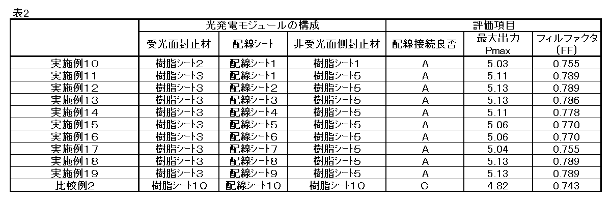
Claims (11)
- 樹脂シートと、
前記樹脂シートの一方の面に設けられた微細配線と、
を有し、
JIS-K7105に準じて測定した前記樹脂シートの350nmの波長における光線透過率が、70%以上である、配線シート。 - JIS-K7105に準じて測定した前記樹脂シートの全光線透過率が80%以上である、請求項1に記載の配線シート。
- 前記樹脂シートが、以下の(A)および(B)のいずれかを含む樹脂材料により形成されている、請求項1または2に記載の配線シート。
(A)エチレンと不飽和カルボン酸を含む共重合体、または前記共重合体のアイオノマー
(B)エチレンと(メタ)アクリル酸グリシジルを含む共重合体 - 前記微細配線が、平行に配置されてなる複数のワイヤにより形成されている、請求項1乃至3のいずれか一項に記載の配線シート。
- 室温条件下、JIS-K7125に準じてタイプDデュロメータを用いて測定した、前記樹脂シートを形成する材料のショアD硬度が、25を超えて200以下である、請求項1乃至4のいずれか一項に記載の配線シート。
- 前記微細配線の一部が、前記樹脂シートに埋設されている請求項1乃至5のいずれか一項に記載の配線シート。
- 前記樹脂シートが、多層構造を有している請求項1乃至6のいずれか一項に記載の配線シート。
- 前記樹脂シートにおける前記微細配線が設けられている面とは反対側の面に、フッ素樹脂およびアクリル樹脂からなる群より選択される1以上を含む材料により形成された層を有する、請求項7に記載の配線シート。
- 請求項1乃至8のいずれか一項に記載された配線シートと、以下の(A)および(B)のいずれかを含む樹脂材料により形成されている封止材と、からなる構造体。
(A)エチレンと不飽和カルボン酸を含む共重合体、または前記共重合体のアイオノマー
(B)エチレンと(メタ)アクリル酸グリシジルを含む共重合体 - 前記封止材が、白色顔料を含む請求項9に記載の構造体。
- 透光性基板と、
請求項1乃至8のいずれか一項に記載された配線シートと、
を備えた光発電モジュール。
Priority Applications (4)
| Application Number | Priority Date | Filing Date | Title |
|---|---|---|---|
| KR1020177022322A KR20170103922A (ko) | 2015-02-06 | 2016-02-05 | 배선 시트, 구조체 및 광발전 모듈 |
| EP16746711.7A EP3255682B1 (en) | 2015-02-06 | 2016-02-05 | Wiring sheet, structure, and photovoltaic generation module |
| CN201680008691.7A CN107408593B (zh) | 2015-02-06 | 2016-02-05 | 配线片材、结构体及光发电模块 |
| JP2016573427A JP6861517B2 (ja) | 2015-02-06 | 2016-02-05 | 配線シート、構造体および光発電モジュール |
Applications Claiming Priority (2)
| Application Number | Priority Date | Filing Date | Title |
|---|---|---|---|
| JP2015-022069 | 2015-02-06 | ||
| JP2015022069 | 2015-02-06 |
Publications (1)
| Publication Number | Publication Date |
|---|---|
| WO2016125880A1 true WO2016125880A1 (ja) | 2016-08-11 |
Family
ID=56564218
Family Applications (1)
| Application Number | Title | Priority Date | Filing Date |
|---|---|---|---|
| PCT/JP2016/053461 Ceased WO2016125880A1 (ja) | 2015-02-06 | 2016-02-05 | 配線シート、構造体および光発電モジュール |
Country Status (6)
| Country | Link |
|---|---|
| EP (1) | EP3255682B1 (ja) |
| JP (2) | JP6861517B2 (ja) |
| KR (1) | KR20170103922A (ja) |
| CN (1) | CN107408593B (ja) |
| TW (1) | TWI693724B (ja) |
| WO (1) | WO2016125880A1 (ja) |
Cited By (8)
| Publication number | Priority date | Publication date | Assignee | Title |
|---|---|---|---|---|
| JP2018046112A (ja) * | 2016-09-13 | 2018-03-22 | パナソニックIpマネジメント株式会社 | 太陽電池モジュール |
| JP2019068070A (ja) * | 2017-10-02 | 2019-04-25 | エルジー エレクトロニクス インコーポレイティド | 太陽電池パネル及びその製造方法 |
| KR20190139933A (ko) * | 2017-04-14 | 2019-12-18 | 마이어 부르거 (스위츠랜드) 아게 | 태양광모듈, 태양광 봉합재 및 태양광모듈의 제조방법 |
| JP2021505751A (ja) * | 2017-12-26 | 2021-02-18 | エルジー・ケム・リミテッド | オレフィン系重合体 |
| JP2021034659A (ja) * | 2019-08-28 | 2021-03-01 | パナソニック株式会社 | 太陽電池モジュール |
| RU2787467C1 (ru) * | 2022-10-11 | 2023-01-09 | Общество с ограниченной ответственностью "Хевел" | Композитно-проволочный электрод для системы контактирования фотоэлектрических преобразователей |
| JP2023086854A (ja) * | 2019-04-08 | 2023-06-22 | 大日本印刷株式会社 | 太陽電池モジュール用の集電ワイヤー固定フィルム、及び、それを用いてなる太陽電池モジュール |
| WO2026058865A1 (ja) * | 2024-09-12 | 2026-03-19 | 大日本印刷株式会社 | 構造体、太陽電池モジュール、および導線付き樹脂フィルム |
Families Citing this family (3)
| Publication number | Priority date | Publication date | Assignee | Title |
|---|---|---|---|---|
| GB202020733D0 (en) * | 2020-12-30 | 2021-02-10 | Rec Solar Pte Ltd | Electrode assembly |
| US20240182699A1 (en) * | 2021-03-29 | 2024-06-06 | Mitsui Chemicals, Inc. | Graft-modified ethylene-based polymer, polyamide composition containing graft-modified ethylene-based polymer and application thereof |
| GB202119068D0 (en) * | 2021-12-29 | 2022-02-09 | Rec Solar Pte Ltd | A unitary film for an electrode assembly of a solar cell |
Citations (7)
| Publication number | Priority date | Publication date | Assignee | Title |
|---|---|---|---|---|
| JP2000186114A (ja) * | 1998-10-16 | 2000-07-04 | Du Pont Mitsui Polychem Co Ltd | 太陽電池封止材料及び太陽電池モジュ―ル |
| JP2000243990A (ja) * | 1999-02-18 | 2000-09-08 | Dainippon Printing Co Ltd | 太陽電池用カバーフィルムおよびその製造方法、およびそのカバーフィルムを用いた太陽電池モジュール |
| JP2004308033A (ja) * | 2003-04-03 | 2004-11-04 | Midori Anzen Co Ltd | ヘルメット |
| JP2005536894A (ja) * | 2002-08-29 | 2005-12-02 | デイ4 エネルギー インコーポレイテッド | 光起電力電池用電極、光起電力電池および光起電力モジュール |
| JP2012138467A (ja) * | 2010-12-27 | 2012-07-19 | Dainippon Printing Co Ltd | 太陽電池封止材料、及びこれを用いた太陽電池モジュール |
| JP2012209462A (ja) * | 2011-03-30 | 2012-10-25 | Lintec Corp | 太陽電池用保護シートおよびその製造方法、ならびに太陽電池モジュール |
| JP2014015544A (ja) * | 2012-07-10 | 2014-01-30 | Bridgestone Corp | エチレン−酢酸ビニル共重合体シート、並びにこれを用いた合わせガラス用中間膜、合わせガラス、太陽電池用封止膜及び太陽電池 |
Family Cites Families (20)
| Publication number | Priority date | Publication date | Assignee | Title |
|---|---|---|---|---|
| CN1531481A (zh) * | 2001-12-28 | 2004-09-22 | 帝人杜邦菲林日本株式会社 | 层合膜 |
| AU2002255303B2 (en) | 2002-05-02 | 2006-07-06 | Sphelar Power Corporation | Light-Receiving panel or light-emitting panel, and manufacturing method thereof |
| JP5366109B2 (ja) * | 2004-12-28 | 2013-12-11 | 三井化学東セロ株式会社 | 太陽電池封止材 |
| JP2006186233A (ja) * | 2004-12-28 | 2006-07-13 | Du Pont Mitsui Polychem Co Ltd | 太陽電池封止材 |
| GB0623936D0 (en) * | 2006-11-29 | 2007-01-10 | Univ Strathclyde | Polymers with transmission into the ultraviolet |
| CN102027415A (zh) * | 2008-05-16 | 2011-04-20 | 昭和电工株式会社 | 图案形成方法 |
| US20100112354A1 (en) * | 2008-10-31 | 2010-05-06 | E. I. Du Pont De Nemours And Company | Articles with abrasion-resistant terionomer layers |
| JP2010251611A (ja) * | 2009-04-17 | 2010-11-04 | Fujifilm Corp | 太陽電池及びその製造方法 |
| MY158305A (en) * | 2009-05-19 | 2016-09-30 | Arkema France | Encapsulant compositions, methods of manufacture and uses thereof |
| CN101993514B (zh) * | 2009-08-18 | 2013-01-23 | 财团法人工业技术研究院 | 聚合物及包含其的光学组件及光电装置 |
| MY161007A (en) * | 2010-10-08 | 2017-03-31 | Mitsui Chemicals Inc | Solar cell sealing material, and solar cell module |
| JP5820109B2 (ja) * | 2010-11-30 | 2015-11-24 | シーアイ化成株式会社 | 太陽電池モジュール用封止フィルム、およびそれを用いた太陽電池モジュール |
| KR20120089909A (ko) * | 2010-12-21 | 2012-08-16 | 에스케이씨 주식회사 | 태양전지 모듈용 봉지재 시트 및 이를 포함하는 태양전지 모듈 |
| JPWO2012090674A1 (ja) * | 2010-12-27 | 2014-06-05 | 旭硝子株式会社 | 太陽電池用表面材、太陽電池用被覆材及び太陽電池モジュール |
| US20120255610A1 (en) * | 2011-04-07 | 2012-10-11 | Bokria Jayesh Ghewarchand | Encapsulant for Terrestrial Photovoltaic Modules |
| KR20130011128A (ko) * | 2011-07-20 | 2013-01-30 | 주식회사 원익아이피에스 | 태양전지모듈 및 그 제조방법 |
| WO2013172023A1 (ja) * | 2012-05-16 | 2013-11-21 | 三井化学東セロ株式会社 | 太陽電池モジュール |
| CN102775549B (zh) * | 2012-08-02 | 2014-03-19 | 江西省科学院应用化学研究所 | 一种高紫外透过率电子封装材料及其制备方法 |
| WO2014045909A1 (ja) * | 2012-09-22 | 2014-03-27 | 株式会社ノリタケカンパニーリミテド | 太陽電池モジュールおよびその製造方法 |
| CN203589047U (zh) * | 2013-11-08 | 2014-05-07 | 蚌埠玻璃工业设计研究院 | 一种非晶硅薄膜太阳能电池芯板 |
-
2016
- 2016-02-05 KR KR1020177022322A patent/KR20170103922A/ko not_active Ceased
- 2016-02-05 CN CN201680008691.7A patent/CN107408593B/zh active Active
- 2016-02-05 WO PCT/JP2016/053461 patent/WO2016125880A1/ja not_active Ceased
- 2016-02-05 TW TW105104054A patent/TWI693724B/zh active
- 2016-02-05 JP JP2016573427A patent/JP6861517B2/ja active Active
- 2016-02-05 EP EP16746711.7A patent/EP3255682B1/en active Active
-
2020
- 2020-05-29 JP JP2020094255A patent/JP6946518B2/ja active Active
Patent Citations (7)
| Publication number | Priority date | Publication date | Assignee | Title |
|---|---|---|---|---|
| JP2000186114A (ja) * | 1998-10-16 | 2000-07-04 | Du Pont Mitsui Polychem Co Ltd | 太陽電池封止材料及び太陽電池モジュ―ル |
| JP2000243990A (ja) * | 1999-02-18 | 2000-09-08 | Dainippon Printing Co Ltd | 太陽電池用カバーフィルムおよびその製造方法、およびそのカバーフィルムを用いた太陽電池モジュール |
| JP2005536894A (ja) * | 2002-08-29 | 2005-12-02 | デイ4 エネルギー インコーポレイテッド | 光起電力電池用電極、光起電力電池および光起電力モジュール |
| JP2004308033A (ja) * | 2003-04-03 | 2004-11-04 | Midori Anzen Co Ltd | ヘルメット |
| JP2012138467A (ja) * | 2010-12-27 | 2012-07-19 | Dainippon Printing Co Ltd | 太陽電池封止材料、及びこれを用いた太陽電池モジュール |
| JP2012209462A (ja) * | 2011-03-30 | 2012-10-25 | Lintec Corp | 太陽電池用保護シートおよびその製造方法、ならびに太陽電池モジュール |
| JP2014015544A (ja) * | 2012-07-10 | 2014-01-30 | Bridgestone Corp | エチレン−酢酸ビニル共重合体シート、並びにこれを用いた合わせガラス用中間膜、合わせガラス、太陽電池用封止膜及び太陽電池 |
Non-Patent Citations (1)
| Title |
|---|
| See also references of EP3255682A4 * |
Cited By (15)
| Publication number | Priority date | Publication date | Assignee | Title |
|---|---|---|---|---|
| JP2018046112A (ja) * | 2016-09-13 | 2018-03-22 | パナソニックIpマネジメント株式会社 | 太陽電池モジュール |
| JP2022159549A (ja) * | 2017-04-14 | 2022-10-17 | マイヤー ブルガー (スイッツァランド) アーゲー | 光電池モジュール、光電池封止剤、及び光電池モジュールを製造する方法 |
| KR20190139933A (ko) * | 2017-04-14 | 2019-12-18 | 마이어 부르거 (스위츠랜드) 아게 | 태양광모듈, 태양광 봉합재 및 태양광모듈의 제조방법 |
| JP2020513163A (ja) * | 2017-04-14 | 2020-04-30 | マイヤー ブルガー (スイッツァランド) アーゲー | 光電池モジュール、光電池封止剤、及び光電池モジュールを製造する方法 |
| KR102607102B1 (ko) | 2017-04-14 | 2023-11-27 | 마이어 부르거 (스위츠랜드) 아게 | 태양광모듈, 태양광 봉합재 및 태양광모듈의 제조방법 |
| JP2019068070A (ja) * | 2017-10-02 | 2019-04-25 | エルジー エレクトロニクス インコーポレイティド | 太陽電池パネル及びその製造方法 |
| US11542352B2 (en) | 2017-12-26 | 2023-01-03 | Lg Chem, Ltd. | Olefin-based polymer |
| JP7055482B2 (ja) | 2017-12-26 | 2022-04-18 | エルジー・ケム・リミテッド | オレフィン系重合体 |
| JP2021505751A (ja) * | 2017-12-26 | 2021-02-18 | エルジー・ケム・リミテッド | オレフィン系重合体 |
| JP2023086854A (ja) * | 2019-04-08 | 2023-06-22 | 大日本印刷株式会社 | 太陽電池モジュール用の集電ワイヤー固定フィルム、及び、それを用いてなる太陽電池モジュール |
| JP7529087B2 (ja) | 2019-04-08 | 2024-08-06 | 大日本印刷株式会社 | 太陽電池モジュール用の集電ワイヤー固定フィルム、及び、それを用いてなる太陽電池モジュール |
| CN112447872A (zh) * | 2019-08-28 | 2021-03-05 | 松下电器产业株式会社 | 太阳能电池模块 |
| JP2021034659A (ja) * | 2019-08-28 | 2021-03-01 | パナソニック株式会社 | 太陽電池モジュール |
| RU2787467C1 (ru) * | 2022-10-11 | 2023-01-09 | Общество с ограниченной ответственностью "Хевел" | Композитно-проволочный электрод для системы контактирования фотоэлектрических преобразователей |
| WO2026058865A1 (ja) * | 2024-09-12 | 2026-03-19 | 大日本印刷株式会社 | 構造体、太陽電池モジュール、および導線付き樹脂フィルム |
Also Published As
| Publication number | Publication date |
|---|---|
| EP3255682B1 (en) | 2020-11-04 |
| EP3255682A1 (en) | 2017-12-13 |
| EP3255682A4 (en) | 2018-10-10 |
| KR20170103922A (ko) | 2017-09-13 |
| JPWO2016125880A1 (ja) | 2017-11-16 |
| TWI693724B (zh) | 2020-05-11 |
| TW201640693A (zh) | 2016-11-16 |
| CN107408593A (zh) | 2017-11-28 |
| JP6946518B2 (ja) | 2021-10-06 |
| JP2020161825A (ja) | 2020-10-01 |
| CN107408593B (zh) | 2022-10-14 |
| JP6861517B2 (ja) | 2021-04-21 |
Similar Documents
| Publication | Publication Date | Title |
|---|---|---|
| JP6946518B2 (ja) | 配線シート、構造体および光発電モジュール | |
| JP5639930B2 (ja) | 太陽電池封止材及びそれを用いて作製された太陽電池モジュール | |
| US9447272B2 (en) | Solar cell sealing material, and solar cell module prepared by using same | |
| US20140360560A1 (en) | Solar cell module having excellent appearance and method for manufacturing same | |
| US9923110B2 (en) | Solar battery module and method of manufacture thereof | |
| EP3358629B1 (en) | Multilayer sheet for solar cell sealing material, method for manufacturing multilayer sheet for solar cell sealing material, and solar cell module | |
| WO2016125882A1 (ja) | 光発電モジュール | |
| EP3357987B1 (en) | Insulating multilayer sheet and solar cell module | |
| JP6520257B2 (ja) | 太陽電池モジュール用の封止材シート、及び太陽電池モジュール | |
| JP5209540B2 (ja) | 太陽電池封止用シート及び太陽電池モジュール | |
| JP2015162498A (ja) | 太陽電池封止材用積層体、太陽電池封止材及び太陽電池モジュール | |
| JP2008311537A (ja) | 太陽電池封止材用シート | |
| JP6747474B2 (ja) | 太陽電池モジュール | |
| KR102713972B1 (ko) | 태양 전지 봉지재용 수지 조성물, 태양 전지 봉지재, 태양 전지 봉지재의 제조 방법 및 태양 전지 모듈 | |
| JP2017011116A (ja) | n型シリコン半導体を使用した太陽電池モジュールのPID対策太陽電池モジュール | |
| WO2015125948A1 (ja) | 太陽電池用pid対策フィルム及びそれを用いたpid対策太陽電池モジュール | |
| TW201420592A (zh) | 太陽電池模組用塡充材片及太陽電池模組之製造方法 | |
| JPWO2014049778A1 (ja) | 太陽電池モジュール用充填材シート、太陽電池封止シート、及び、太陽電池モジュールの製造方法 | |
| KR102761495B1 (ko) | 태양 전지 밀봉재용 수지 조성물, 태양 전지 밀봉재, 태양 전지 밀봉재의 제조 방법 및 태양 전지 모듈 | |
| JP2016174124A (ja) | 太陽電池モジュール用の封止材シート、及び太陽電池モジュール | |
| JP2017123364A (ja) | 太陽電池モジュール用封止材及び太陽電池モジュール | |
| JP2016072599A (ja) | 太陽電池モジュール用の封止材シート組成物、封止材シート、及び太陽電池モジュール |
Legal Events
| Date | Code | Title | Description |
|---|---|---|---|
| 121 | Ep: the epo has been informed by wipo that ep was designated in this application |
Ref document number: 16746711 Country of ref document: EP Kind code of ref document: A1 |
|
| ENP | Entry into the national phase |
Ref document number: 2016573427 Country of ref document: JP Kind code of ref document: A |
|
| NENP | Non-entry into the national phase |
Ref country code: DE |
|
| ENP | Entry into the national phase |
Ref document number: 20177022322 Country of ref document: KR Kind code of ref document: A |
|
| REEP | Request for entry into the european phase |
Ref document number: 2016746711 Country of ref document: EP |