WO2016125886A1 - 通信制御装置及び基地局 - Google Patents
通信制御装置及び基地局 Download PDFInfo
- Publication number
- WO2016125886A1 WO2016125886A1 PCT/JP2016/053477 JP2016053477W WO2016125886A1 WO 2016125886 A1 WO2016125886 A1 WO 2016125886A1 JP 2016053477 W JP2016053477 W JP 2016053477W WO 2016125886 A1 WO2016125886 A1 WO 2016125886A1
- Authority
- WO
- WIPO (PCT)
- Prior art keywords
- bearer
- base station
- communication control
- control unit
- user terminal
- Prior art date
- Legal status (The legal status is an assumption and is not a legal conclusion. Google has not performed a legal analysis and makes no representation as to the accuracy of the status listed.)
- Ceased
Links
Images


Classifications
-
- H—ELECTRICITY
- H04—ELECTRIC COMMUNICATION TECHNIQUE
- H04W—WIRELESS COMMUNICATION NETWORKS
- H04W76/00—Connection management
- H04W76/10—Connection setup
- H04W76/19—Connection re-establishment
-
- H—ELECTRICITY
- H04—ELECTRIC COMMUNICATION TECHNIQUE
- H04L—TRANSMISSION OF DIGITAL INFORMATION, e.g. TELEGRAPHIC COMMUNICATION
- H04L5/00—Arrangements affording multiple use of the transmission path
- H04L5/003—Arrangements for allocating sub-channels of the transmission path
- H04L5/0032—Distributed allocation, i.e. involving a plurality of allocating devices, each making partial allocation
-
- H—ELECTRICITY
- H04—ELECTRIC COMMUNICATION TECHNIQUE
- H04W—WIRELESS COMMUNICATION NETWORKS
- H04W16/00—Network planning, e.g. coverage or traffic planning tools; Network deployment, e.g. resource partitioning or cells structures
- H04W16/14—Spectrum sharing arrangements between different networks
-
- H—ELECTRICITY
- H04—ELECTRIC COMMUNICATION TECHNIQUE
- H04W—WIRELESS COMMUNICATION NETWORKS
- H04W16/00—Network planning, e.g. coverage or traffic planning tools; Network deployment, e.g. resource partitioning or cells structures
- H04W16/24—Cell structures
- H04W16/32—Hierarchical cell structures
-
- H—ELECTRICITY
- H04—ELECTRIC COMMUNICATION TECHNIQUE
- H04W—WIRELESS COMMUNICATION NETWORKS
- H04W36/00—Hand-off or reselection arrangements
- H04W36/0005—Control or signalling for completing the hand-off
- H04W36/0011—Control or signalling for completing the hand-off for data sessions of end-to-end connection
- H04W36/0027—Control or signalling for completing the hand-off for data sessions of end-to-end connection for a plurality of data sessions of end-to-end connections, e.g. multi-call or multi-bearer end-to-end data connections
-
- H—ELECTRICITY
- H04—ELECTRIC COMMUNICATION TECHNIQUE
- H04W—WIRELESS COMMUNICATION NETWORKS
- H04W68/00—User notification, e.g. alerting and paging, for incoming communication, change of service or the like
-
- H—ELECTRICITY
- H04—ELECTRIC COMMUNICATION TECHNIQUE
- H04W—WIRELESS COMMUNICATION NETWORKS
- H04W72/00—Local resource management
- H04W72/04—Wireless resource allocation
- H04W72/044—Wireless resource allocation based on the type of the allocated resource
- H04W72/0446—Resources in time domain, e.g. slots or frames
-
- H—ELECTRICITY
- H04—ELECTRIC COMMUNICATION TECHNIQUE
- H04W—WIRELESS COMMUNICATION NETWORKS
- H04W72/00—Local resource management
- H04W72/20—Control channels or signalling for resource management
- H04W72/23—Control channels or signalling for resource management in the downlink direction of a wireless link, i.e. towards a terminal
-
- H—ELECTRICITY
- H04—ELECTRIC COMMUNICATION TECHNIQUE
- H04W—WIRELESS COMMUNICATION NETWORKS
- H04W72/00—Local resource management
- H04W72/50—Allocation or scheduling criteria for wireless resources
- H04W72/54—Allocation or scheduling criteria for wireless resources based on quality criteria
- H04W72/541—Allocation or scheduling criteria for wireless resources based on quality criteria using the level of interference
-
- H—ELECTRICITY
- H04—ELECTRIC COMMUNICATION TECHNIQUE
- H04W—WIRELESS COMMUNICATION NETWORKS
- H04W76/00—Connection management
- H04W76/10—Connection setup
-
- H—ELECTRICITY
- H04—ELECTRIC COMMUNICATION TECHNIQUE
- H04W—WIRELESS COMMUNICATION NETWORKS
- H04W76/00—Connection management
- H04W76/10—Connection setup
- H04W76/15—Setup of multiple wireless link connections
-
- H—ELECTRICITY
- H04—ELECTRIC COMMUNICATION TECHNIQUE
- H04W—WIRELESS COMMUNICATION NETWORKS
- H04W76/00—Connection management
- H04W76/20—Manipulation of established connections
-
- H—ELECTRICITY
- H04—ELECTRIC COMMUNICATION TECHNIQUE
- H04W—WIRELESS COMMUNICATION NETWORKS
- H04W76/00—Connection management
- H04W76/30—Connection release
-
- H—ELECTRICITY
- H04—ELECTRIC COMMUNICATION TECHNIQUE
- H04W—WIRELESS COMMUNICATION NETWORKS
- H04W88/00—Devices specially adapted for wireless communication networks, e.g. terminals, base stations or access point devices
- H04W88/18—Service support devices; Network management devices
-
- H—ELECTRICITY
- H04—ELECTRIC COMMUNICATION TECHNIQUE
- H04W—WIRELESS COMMUNICATION NETWORKS
- H04W92/00—Interfaces specially adapted for wireless communication networks
- H04W92/04—Interfaces between hierarchically different network devices
- H04W92/12—Interfaces between hierarchically different network devices between access points and access point controllers
-
- H—ELECTRICITY
- H04—ELECTRIC COMMUNICATION TECHNIQUE
- H04W—WIRELESS COMMUNICATION NETWORKS
- H04W88/00—Devices specially adapted for wireless communication networks, e.g. terminals, base stations or access point devices
- H04W88/08—Access point devices
Definitions
- the present invention relates to a communication control device and a base station used in a mobile communication system.
- Non-Patent Document 1 it is regarded as a problem that the processing load in the mobility management apparatus increases due to a large number of small cell base stations. In particular, when user terminal handovers frequently occur, such a problem becomes prominent (see, for example, Non-Patent Document 1).
- the communication control apparatus is used in a mobile communication system.
- the said communication control apparatus is provided with the control part which performs control regarding the radio
- the radio access bearer includes a first bearer between the user terminal and a base station, and a second bearer between the base station and the serving gateway.
- the communication control device is located on the second bearer. Even when the first bearer is released, the control unit maintains at least a part of the second bearer without releasing it.
- the base station is used in a mobile communication system.
- the base station includes a control unit that performs control related to a radio access bearer established between the user terminal and a serving gateway.
- the radio access bearer is configured by a first bearer between the user terminal and the base station, and a second bearer between the base station and the serving gateway.
- a communication control device is located on the second bearer.
- the processing load associated with the establishment of such a radio access bearer can be higher than the processing load associated with the handover described above.
- the embodiment provides a communication control device and a base station that can reduce the processing load in the core network.
- the communication control apparatus is used in a mobile communication system.
- the said communication control apparatus is provided with the control part which performs control regarding the radio
- the radio access bearer includes a first bearer between the user terminal and a base station, and a second bearer between the base station and the serving gateway.
- the communication control device is located on the second bearer. Even when the first bearer is released, the control unit maintains at least a part of the second bearer without releasing it.
- the second bearer is configured by a first section between the base station and the communication control apparatus, and a second section between the communication control apparatus and the serving gateway.
- the control unit maintains the second section without releasing it even when the first bearer is released.
- control unit maintains the second section without releasing it by holding the tunnel end point identifier of the second section in association with the identifier of the user terminal.
- the communication control apparatus receives a bearer re-establishment request from the base station after the first bearer is released.
- the control unit re-establishes the second bearer by re-establishing the first interval based on the bearer re-establishment request.
- control unit transmits a bearer re-establishment response for establishing the first bearer to the base station based on the bearer re-establishment request.
- the radio access bearer is reestablished by the second bearer reestablished by the communication control device and the first bearer established by the base station.
- the communication control apparatus accommodates a plurality of base stations.
- the control unit transmits a paging request for requesting paging of the user terminal to the plurality of base stations.
- the control unit re-establishes the second bearer by re-establishing the first section with the specific base station. Establish.
- control unit transmits a bearer establishment request for establishing the first bearer to the specific base station.
- the radio access bearer is reestablished by the second bearer reestablished by the communication control device and the first bearer established by the specific base station.
- the control unit when the paging fails in all of the plurality of base stations, the control unit transmits a release notification of the radio access bearer to the mobility management device, and returns the data to the serving gateway.
- the base station is used in a mobile communication system.
- the base station includes a control unit that performs control related to a radio access bearer established between the user terminal and a serving gateway.
- the radio access bearer is configured by a first bearer between the user terminal and the base station, and a second bearer between the base station and the serving gateway.
- a communication control device is located on the second bearer.
- the control unit when the base station receives a bearer re-establishment response to the bearer re-establishment request from the communication control device, the control unit establishes the first bearer with the user terminal.
- the control unit when the base station receives a paging request for requesting paging of the user terminal from the communication control apparatus, the control unit performs paging of the user terminal. When the paging of the user terminal is successful, the control unit transmits a paging acknowledgment to the paging request to the communication control device.
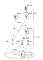
- FIG. 1 is a diagram illustrating a configuration of an LTE system according to the embodiment.
- the LTE system includes an E-UTRAN (Evolved-UMTS Terrestrial Radio Access Network) 10, an EPC (Evolved Packet Core) 20, and a UE (User Equipment) 100.
- the UE 100 corresponds to a user terminal.
- the E-UTRAN 10 corresponds to a radio access network.
- the EPC 20 corresponds to a core network.
- the E-UTRAN 10 includes an eNB 200 (evolved Node-B) and a RAN GW (Radio Access Network Gateway) 300.
- the eNB 200 corresponds to a base station.
- the RAN GW 300 corresponds to a communication control device.
- the eNB 200 manages the cell and performs radio communication with the UE 100 in the RRC (Radio Resource Control) connected mode in the own cell.
- the eNB 200 has a radio resource management (RRM) function, a routing function of user data (hereinafter simply referred to as “data”), a measurement control function for mobility control / scheduling, and the like.
- RRM radio resource management
- data a routing function of user data
- measurement control function for mobility control / scheduling and the like.
- “cell” is used as a term indicating a minimum unit of a radio communication area, and is also used as a term indicating a function of performing radio communication with the UE 100.
- an eNB 200-1 that is a macro cell base station that manages a macro cell
- an eNB 200-2 that is a small cell base station that manages a small cell # 1
- an eNB 200 that is a small cell base station that manages a small cell # 2.
- Small cell # 1 and small cell # 2 are arranged in a macro cell. By disposing small cells in the macro cell, the system capacity can be increased.
- the RAN GW 300 accommodates a plurality of eNBs 200 (eNB 200-2 and eNB 200-3). Specifically, the RAN GW 300 is connected to the eNB 200 via the S1 interface.
- the S1 interface includes an S1-U interface corresponding to a user plane (U plane) that handles data, and an S1-MME interface corresponding to a control plane (C plane) that handles control signals (signaling).
- U plane user plane
- C plane control plane
- the EPC 20 includes an MME (Mobility Management Entity) 500, an S-GW (Serving-Gateway) 400, and a P-GW (PDN-Gateway) 600.
- MME Mobility Management Entity
- S-GW Serving-Gateway
- P-GW Packet-Gateway
- the MME 500 corresponds to a mobility management device.
- the S-GW 400 is a core network device corresponding to the U plane, and performs data transfer control and the like.
- the MME 500 is a core network device corresponding to the C plane, and performs various mobility controls and the like for the UE 100.
- the P-GW 600 functions as a connection point with the Internet as an external network.
- the eNB 200-1 is connected to the S-GW 400 via the S1-U interface and is connected to the MME 500 via the S1-MME interface.
- the RAN GW 300 is connected to the S-GW 400 via the S1-U interface and is connected to the MME 500 via the S1-MME interface.
- the S-GW 400 is connected to the P-GW 600 via the S5 / S8 interface.
- the UE 100 is a mobile communication device. If there is an RRC connection between the UE 100 and the eNB 200, the UE 100 is in the RRC connected mode, and if not, the UE 100 is in the RRC idle mode. The UE 100 in the RRC connected mode performs handover for switching the serving cell as it moves. The UE 100 in the RRC idle mode performs cell reselection for switching the serving cell as it moves.
- FIG. 1 illustrates an example in which the serving cell of the UE 100 is the small cell # 1.
- E-RAB E-UTRAN Radio Access Bearer
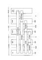
- FIG. 2 is a diagram for explaining E-RAB.
- the UE 100 communicates with a partner device (Peer Entity) on the Internet.
- a partner device Packeer Entity
- data transmitted and received by the UE 100 is carried by an EPS (Evolved Packet System) bearer between the UE 100 and the P-GW 600 and an external bearer between the P-GW 600 and the Internet.
- EPS Evolved Packet System
- the EPS bearer includes an E-RAB between the UE 100 and the S-GW 400, and an S5 / S8 bearer between the S-GW 400 and the P-GW 600.
- An S5 / S8 bearer is established on the S5 / S8 interface.
- the E-RAB exists, the E-RAB has a one-to-one correspondence with the EPS bearer.
- the S-GW 400 stores the correspondence relationship between the S5 / S8 bearer and the S1 bearer.
- the E-RAB includes a data radio bearer (Radio Bearer) between the UE 100 and the eNB 200, and an S1 bearer (S1 Bearer) between the eNB 200 and the S-GW 400.
- Radio Bearer Radio Bearer
- S1 Bearer S1 bearer
- the data radio bearer corresponds to the first bearer
- the S1 bearer corresponds to the second bearer.
- the S1 bearer is established on the S1-U interface. If there is a data radio bearer, the data radio bearer has a one-to-one correspondence with the EPS bearer / E-RAB.
- the eNB 200 stores the correspondence relationship between the S1 bearer and the data radio bearer.
- the MME 500 transmits an E-RAB establishment request to the eNB 200.
- the eNB 200 establishes the data radio bearer and the S1 bearer in response to receiving the E-RAB establishment request from the MME 500, and transmits an E-RAB establishment response to the MME 500.
- the MME 500 transmits an E-RAB establishment instruction to the eNB 200.
- the eNB 200 releases the data radio bearer and the S1 bearer, and transmits an E-RAB release completion notification to the MME 500.
- the E-RAB When the eNB 200 releases the RRC connection with the UE 100, the E-RAB is released. And when establishing RRC connection with UE100, E-RAB is established. Along with such E-RAB establishment / release, signaling occurs between the eNB 200 and the MME 500. Thereby, the processing load in MME500 may become high.
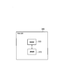
- FIG. 3 is a block diagram of the RAN GW 300 according to the embodiment.
- the RAN GW 300 includes a communication unit 310 and a control unit 320.
- the communication unit 310 is used for communication on the S1 interface under the control of the control unit 320.
- the control unit 320 performs various controls in the RAN GW 300.
- the control unit 320 includes a processor and a memory.
- the memory stores a program executed by the processor and information used for processing by the processor. It includes a CPU (Central Processing Unit) that executes various programs by executing programs stored in the memory.
- the processor executes various processes described later.
- control unit 320 performs control related to E-RAB established between the UE 100 and the S-GW 400. Even if the data radio bearer is released, the control unit 320 maintains at least a part of the S1 bearer without releasing it. That is, the control unit 320 maintains at least a part of the S1 bearer without releasing the UE 100 that has transitioned to the RRC idle mode.
- the S1 bearer includes a first section between the eNB 200 and the RAN GW 300 and a second section between the RAN GW 300 and the S-GW 400. Even if the data radio bearer is released, the control unit 320 maintains the second section without releasing it.
- the control unit 320 maintains the second section without releasing it by holding the tunnel end point identifier of the second section in association with the identifier of the UE 100.
- the tunnel end point identifier is, for example, GTP TEID (GPRS Tunneling Protocol Tunnel Endpoint ID).
- the identifier of the UE 100 is an MME UE S1AP ID, IMSI (International Mobile Subscriber Identity), IMEI (International Mobile Equipment Identity), C-RNTI (Cell Radio Network Temporary Identity), GUTI (Globally Unique Temporary Identity), or IP address. May be.
- the control unit 320 holds the identifiers (and cell identifiers) of the eNBs 200 (eNB 200-2 and eNB 200-3) subordinate to the RAN GW 300.
- the identifier of the eNB 200 may be an eNB UE S1AP ID.
- the control unit 320 acquires these pieces of information before the timing when the UE 100 releases the RRC connection. Or control part 320 may acquire these information from eNB200, when UE100 releases an RRC connection.
- control part 320 may manage the timer corresponding to the period which should maintain the 2nd area of S1 bearer. In this case, the control unit 320 activates the timer when the data radio bearer is released, maintains the second section of the S1 bearer until the timer expires, and when the timer expires, the second section Is released.
- the RAN GW 300 receives a bearer re-establishment request from the eNB 200 after the data radio bearer is released.
- the control unit 320 reestablishes the S1 bearer by reestablishing the first section based on the bearer reestablishment request.
- the control part 320 transmits the bearer re-establishment response for establishing a data radio bearer to eNB200 based on a bearer re-establishment request
- the E-RAB is reestablished by the S1 bearer reestablished by the RAN GW 300 and the data radio bearer established by the eNB 200.
- the control unit 320 when the RAN GW 300 receives data addressed to the UE 100 from the S-GW 400, the control unit 320 sends a paging request for requesting paging of the UE 100 to a plurality of eNBs 200 (eNB 200). -2 and eNB 200-3).
- eNB 200 eNB 200
- eNB 200 eNB 200
- eNB 200-3 eNB 200-3
- the control unit 320 re-establishes the S1 bearer by re-establishing the first section with the specific eNB 200.
- the control part 320 transmits the bearer establishment request
- the E-RAB is reestablished by the S1 bearer reestablished by the RAN GW 300 and the data radio bearer established by the specific eNB 200.
- the control unit 320 transmits an E-RAB release notification to the MME 500 and returns data to the S-GW 400.
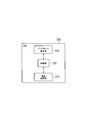
- FIG. 4 is a block diagram of the eNB 200 (base station). As illustrated in FIG. 4, the eNB 200 includes a radio communication unit 210, a backhaul communication unit 220, and a control unit 230.
- the wireless communication unit 210 is used for communication with the UE 100 under the control of the control unit 230.
- the backhaul communication unit 220 is used for communication on the S1 interface under the control of the control unit 230.
- the control unit 230 performs various controls in the eNB 200.
- the control unit 230 includes a processor and a memory.
- the memory stores a program executed by the processor and information used for processing by the processor.
- the processor includes a baseband processor that performs modulation / demodulation and encoding / decoding of a baseband signal, and a CPU that executes various processes by executing a program stored in a memory.
- the processor executes various processes described later.
- control unit 230 performs control related to E-RAB established between the UE 100 and the S-GW 400.
- control unit 230 when receiving a connection request from UE 100 after releasing the data radio bearer, control unit 230 transmits a bearer re-establish request to RAN GW 300 located on S1 bearer. And when eNB200 receives the bearer re-establishment response with respect to a bearer re-establishment request from RAN GW300, the control part 230 establishes the data radio bearer with UE100.
- the control unit 230 performs the paging of the UE 100.
- the control unit 230 transmits a paging acknowledgment to the RAN GW 300 in response to the paging request.
- FIG. 5 is a sequence diagram showing a bearer re-establishment sequence 1 according to the embodiment.
- the UE 100 In the initial state of FIG. 5, the UE 100 is in the RRC idle mode, and the data radio bearer is released. However, the second section of S1 bearer (the section between RAN GW 300 and S-GW 400) is maintained without being released (step S101).
- step S102 the UE 100 transmits a connection request (RRC Connection Request) message to the eNB 200.
- RRC Connection Request a connection request (RRC Connection Request) message
- the eNB 200 transmits a bearer re-establishment request (E-RAB Resume Request) message to the RAN GW 300 in response to reception of the “RRC Connection Request” message.
- the “E-RAB Resume Request” message includes, for example, the UE 100 identifier, “MME UE S1AP ID”, “eNB UE S1AP ID”, NAS-PDU, and the like.
- the eNB 200 does not perform signaling to the MME 500.
- step S104 the RAN GW 300 confirms whether or not the S1 bearer of the corresponding UE 100 is maintained in response to the reception of the “E-RAB Resume Request” message. For example, the RAN GW 300 searches for the combination of the corresponding GTP TEID and UE ID from the combination of the held GTP TEID and the identifier of the UE 100.
- the RAN GW 300 transmits a failure notification (E-RAB Resume Failure) message to the eNB 200.
- the eNB 200 transmits a bearer establishment (E-RAB Setup) message to the MME 500 in response to reception of the “E-RAB Resume Failure” message.
- the subsequent operation is the same as the general E-RAB establishment procedure.
- a failure notification message may be transmitted from the RAN GW 300 to the MME 500.
- the MME 500 may perform E-RAB establishment by transmitting a bearer establishment (E-RAB Setup) message or an E-RAB establishment request to the eNB 200.
- step S105 the RAN GW 300 sends a bearer re-establishment response (E-RAB Resume Response) message to the eNB 200 to establish the data radio bearer.
- E-RAB Resume Response includes “MME UE S1AP ID”, “eNB UE S1AP ID”, “UE Aggregate Maximum Bit Rate”, “E-RAB to be Setup List”, and the like.
- the eNB 200 receives the “E-RAB Resume Response” message.
- step S106 the RAN GW 300 and the eNB 200 re-establish the first section of the S1 bearer (the section between the eNB 200 and the RAN GW 300).
- the first section may be a virtual new bearer.
- the RAN GW 300 associates the first section of the S1 bearer with the maintained second section.
- step S107 the eNB 200 transmits an RRC reconfiguration (RRC Connection Reconfiguration) message for establishing a data radio bearer to the UE 100.
- the UE 100 receives the “RRC Connection Reconfiguration” message.
- step S108 the eNB 200 and the UE 100 establish a data radio bearer.
- the eNB 200 associates the established data radio bearer with the S1 bearer.
- the E-RAB between the UE 100 and the S-GW 400 is re-established (repaired).
- FIG. 6 is a sequence diagram showing a bearer re-establishment sequence 2 according to the embodiment.
- the UE 100 In the initial state of FIG. 6, the UE 100 is in the RRC idle mode, and the data radio bearer is released. However, the second section of S1 bearer (the section between RAN GW 300 and S-GW 400) is maintained without being released (step S201).
- the S-GW 400 transmits data addressed to the UE 100 (that is, downlink data) to the RAN GW 300.
- the RAN GW 300 receives the data.
- the RAN GW 300 searches for the combination of the corresponding GTP TEID and UE ID from the held combinations of the GTP TEID and UE ID in response to reception of the downlink data.
- the RAN GW 300 does not know which eNB 200 cell the UE 100 is in.
- the RAN GW 300 transmits a paging request (RAN Paging Request) message for requesting the paging of the UE 100 to the plurality of eNBs 200 (eNB 200-2 and eNB 200-3).
- the “RAN Paging Request” message includes the UE 100 identifier (UE ID).
- Step S204 the plurality of eNBs 200 transmit a paging (RAN Paging) message in the own cell in response to reception of the “RAN Paging Request” message.
- RAN Paging paging
- the UE 100 is in the cell of any one of the plurality of eNBs 200 (specific eNB 200).
- step S205 the UE 100 transmits a connection request (RRC Connection Request) message to the specific eNB 200 in response to reception of the “RAN Paging” message.
- RRC Connection Request connection request
- Step S206 the specific eNB 200 transmits a paging response (RAN Paging Response) message to the RAN GW 300 in response to the reception of the “RRC Connection Request” message.
- the “RAN Paging Response” message includes a UE identifier, “MMEMUE S1AP ID”, “eNB UE S1AP ID”, and the like.
- a specific eNB 200 does not perform signaling to the MME 500.
- the RAN GW 300 transmits a bearer re-establishment instruction (E-RAB Resume Command) message for establishing a data radio bearer to the specific eNB 200.
- E-RAB Resume Command includes “MME UE S1AP ID”, “eNB UE S1AP ID”, “UE Aggregate Maximum Bit Rate”, “E-RAB to be Setup List”, and the like.
- the specific eNB 200 receives the “E-RAB Resume Command” message.
- step S208 the RAN GW 300 and the specific eNB 200 reestablish the first section of the S1 bearer (section between the eNB 200 and the RAN GW 300).
- the first section may be a virtual new bearer.
- the RAN GW 300 associates the first section of the S1 bearer with the maintained second section.
- step S209 the specific eNB 200 transmits a bearer re-establishment completion (E-RAB Resume Complete) message to the RAN GW 300.
- the “E-RAB Resume Complete” message includes “MME UE S1AP ID”, “eNB UE S1AP ID”, “E-RAB Setup List”, and the like.
- step S210 the specific eNB 200 transmits an RRC reconfiguration (RRC Connection Reconfiguration) message for establishing the data radio bearer to the UE 100.
- the UE 100 receives the “RRC Connection Reconfiguration” message.
- step S211 the specific eNB 200 and the UE 100 establish a data radio bearer.
- the specific eNB 200 associates the established data radio bearer with the S1 bearer.
- the E-RAB between the UE 100 and the S-GW 400 is re-established (repaired).
- the RAN GW 300 detects the timeout of the “RAN Paging Response” message and performs the following operation.
- the RAN GW 300 determines that paging has failed in all of the plurality of eNBs 200, transmits an E-RAB release indication (E-RAB Release Indication) message to the MME 500, and transmits downlink data to the S- Return to GW 400 (forwarding).
- E-RAB Release Indication E-RAB Release Indication
- the RAN GW 300 maintains at least a part of the S1 bearer without releasing it even when the data radio bearer is released. Accordingly, the RAN GW 300 can control the establishment of the E-RAB instead of the MME 500 based on the maintained S1 bearer. Therefore, since the signaling between the eNB 200 and the MME 500 can be suppressed when establishing the E-RAB, the processing load on the MME 500 can be reduced.
- the RAN GW 300 accommodates a plurality of eNBs 200 has been described.
- the RAN GW 300 may accommodate only one eNB 200.
- an S1-MME interface may not be set between the RAN GW 300 and the eNB 200.
- the RAN GW 300 may be provided at the boundary between the E-UTRAN 10 and the EPC 20.
- the LTE system is exemplified as the mobile communication system.
- the present invention is not limited to LTE systems.
- the present invention may be applied to a system other than the LTE system.
- the present invention is useful in the communication field.
Landscapes
- Engineering & Computer Science (AREA)
- Signal Processing (AREA)
- Computer Networks & Wireless Communication (AREA)
- Quality & Reliability (AREA)
- Mobile Radio Communication Systems (AREA)
Abstract
Description
ユーザ端末が基地局との接続を解放する場合、当該ユーザ端末とサービングゲートウェイとの間の無線アクセスベアラも解放される。
(移動通信システム)
以下において、3GPP規格に基づく移動通信システムであるLTEシステムに本発明を適用する場合の実施形態を説明する。図1は、実施形態に係るLTEシステムの構成を示す図である。
以下において、E-RAB(E-UTRAN Radio Access Bearer)について説明する。E-RABは、無線アクセスベアラに相当する。図2は、E-RABを説明するための図である。
以下において、実施形態に係るRAN GW300(通信制御装置)について説明する。RAN GW300は、eNB200とS-GW400との間のS1ベアラ上に位置する(図1参照)。図3は、実施形態に係るRAN GW300のブロック図である。
図4は、eNB200(基地局)のブロック図である。図4に示すように、eNB200は、無線通信部210、バックホール通信部220、及び制御部230を備える。
以下において、実施形態に係るベアラ再確立シーケンス1について説明する。図5は、実施形態に係るベアラ再確立シーケンス1を示すシーケンス図である。図5の初期状態において、UE100はRRCアイドルモードであり、データ無線ベアラが解放されている。しかしながら、S1ベアラの第2の区間(RAN GW300とS-GW400との間の区間)については、解放せずに維持されている(ステップS101)。
以下において、実施形態に係るベアラ再確立シーケンス2について説明する。図6は、実施形態に係るベアラ再確立シーケンス2を示すシーケンス図である。図6の初期状態において、UE100はRRCアイドルモードであり、データ無線ベアラが解放されている。しかしながら、S1ベアラの第2の区間(RAN GW300とS-GW400との間の区間)については、解放せずに維持されている(ステップS201)。
上述したように、RAN GW300は、データ無線ベアラが解放された場合であっても、S1ベアラの少なくとも一部の区間を解放せずに維持する。これにより、RAN GW300は、維持しているS1ベアラに基づいて、MME500の代わりにE-RABの確立を制御することができる。よって、E-RABを確立する際に、eNB200とMME500との間でのシグナリングを抑制することができるため、MME500における処理負荷を低減することができる。
上述した実施形態において、RAN GW300が複数のeNB200を収容する一例を説明した。しかしながら、RAN GW300は、1つのeNB200のみを収容してもよい。また、RAN GW300とeNB200との間には、S1-MMEインターフェイスが設定されていなくてもよい。RAN GW300は、E-UTRAN10とEPC20との境界に設けられてもよい。
米国仮出願第62/112764号(2015年2月6日出願)の全内容が参照により本願明細書に組み込まれている。
Claims (11)
- 移動通信システムにおいて用いられる通信制御装置であって、
ユーザ端末とサービングゲートウェイとの間に確立される無線アクセスベアラに関する制御を行う制御部を備え、
前記無線アクセスベアラは、前記ユーザ端末と基地局との間の第1のベアラ、及び前記基地局と前記サービングゲートウェイとの間の第2のベアラにより構成され、
前記通信制御装置は、前記第2のベアラ上に位置しており、
前記制御部は、前記第1のベアラが解放された場合であっても、前記第2のベアラの少なくとも一部の区間を解放せずに維持することを特徴とする通信制御装置。 - 前記第2のベアラは、前記基地局と前記通信制御装置との間の第1の区間、及び前記通信制御装置と前記サービングゲートウェイとの間の第2の区間により構成され、
前記制御部は、前記第1のベアラが解放された場合であっても、前記第2の区間を解放せずに維持することを特徴とする請求項1に記載の通信制御装置。 - 前記制御部は、前記第2の区間のトンネル終点識別子を前記ユーザ端末の識別子と関連付けて保持することにより、前記第2の区間を解放せずに維持することを特徴とする請求項2に記載の通信制御装置。
- 前記通信制御装置は、前記第1のベアラが解放された後において、ベアラ再確立要求を前記基地局から受信し、
前記制御部は、前記ベアラ再確立要求に基づいて、前記第1の区間を再確立することにより、前記第2のベアラを再確立することを特徴とする請求項2に記載の通信制御装置。 - 前記制御部は、前記ベアラ再確立要求に基づいて、前記第1のベアラを確立させるためのベアラ再確立応答を前記基地局に送信し、
前記通信制御装置により再確立された第2のベアラ及び前記基地局により確立された前記第1のベアラにより、前記無線アクセスベアラが再確立されることを特徴とする請求項4に記載の通信制御装置。 - 前記通信制御装置は、複数の基地局を収容しており、
前記ユーザ端末宛てのデータを前記サービングゲートウェイから前記通信制御装置が受信した場合、前記制御部は、前記ユーザ端末のページングを要求するページング要求を前記複数の基地局に送信し、
前記複数の基地局のうち特定の基地局において前記ページングに成功した場合、前記制御部は、前記特定の基地局との前記第1の区間を再確立することにより、前記第2のベアラを再確立することを特徴とする請求項2に記載の通信制御装置。 - 前記制御部は、前記特定の基地局に対して、前記第1のベアラを確立させるためのベアラ確立要求を送信し、
前記通信制御装置により再確立された第2のベアラ及び前記特定の基地局により確立された前記第1のベアラにより、前記無線アクセスベアラが再確立されることを特徴とする請求項6に記載の通信制御装置。 - 前記複数の基地局の全てにおいて前記ページングに失敗した場合、前記制御部は、前記無線アクセスベアラの解放通知を移動管理装置に送信し、前記データを前記サービングゲートウェイに返送することを特徴とする請求項6に記載の通信制御装置。
- 移動通信システムにおいて用いられる基地局であって、
前記ユーザ端末とサービングゲートウェイとの間に確立される無線アクセスベアラに関する制御を行う制御部を備え、
前記無線アクセスベアラは、前記ユーザ端末と前記基地局との間の第1のベアラと、前記基地局と前記サービングゲートウェイとの間の第2のベアラと、により構成され、
前記第2のベアラ上に通信制御装置が位置しており、
前記制御部は、前記第1のベアラを解放した後において、前記ユーザ端末から接続要求を受信すると、前記通信制御装置に対してベアラ再確立要求を送信することを特徴とする基地局。 - 前記ベアラ再確立要求に対するベアラ再確立応答を前記通信制御装置から前記基地局が受信した場合、前記制御部は、前記ユーザ端末との前記第1のベアラを確立することを特徴とする請求項9に記載の基地局。
- 前記ユーザ端末のページングを要求するページング要求を前記通信制御装置から前記基地局が受信した場合、前記制御部は、前記ユーザ端末のページングを行い、
前記ユーザ端末のページングに成功した場合、前記制御部は、前記ページング要求に対するページング肯定応答を前記通信制御装置に送信することを特徴とする請求項9に記載の基地局。
Priority Applications (3)
| Application Number | Priority Date | Filing Date | Title |
|---|---|---|---|
| JP2016573431A JPWO2016125886A1 (ja) | 2015-02-06 | 2016-02-05 | 通信制御装置及び基地局 |
| EP16746717.4A EP3255955A4 (en) | 2015-02-06 | 2016-02-05 | Communication control device and base station |
| US15/547,572 US10356835B2 (en) | 2015-02-06 | 2016-02-05 | Communication control apparatus and base station |
Applications Claiming Priority (2)
| Application Number | Priority Date | Filing Date | Title |
|---|---|---|---|
| US201562112764P | 2015-02-06 | 2015-02-06 | |
| US62/112,764 | 2015-02-06 |
Publications (1)
| Publication Number | Publication Date |
|---|---|
| WO2016125886A1 true WO2016125886A1 (ja) | 2016-08-11 |
Family
ID=56564224
Family Applications (3)
| Application Number | Title | Priority Date | Filing Date |
|---|---|---|---|
| PCT/JP2016/053477 Ceased WO2016125886A1 (ja) | 2015-02-06 | 2016-02-05 | 通信制御装置及び基地局 |
| PCT/JP2016/053479 Ceased WO2016125887A1 (ja) | 2015-02-06 | 2016-02-05 | 基地局 |
| PCT/JP2016/053480 Ceased WO2016125888A1 (ja) | 2015-02-06 | 2016-02-05 | ユーザ端末及び基地局 |
Family Applications After (2)
| Application Number | Title | Priority Date | Filing Date |
|---|---|---|---|
| PCT/JP2016/053479 Ceased WO2016125887A1 (ja) | 2015-02-06 | 2016-02-05 | 基地局 |
| PCT/JP2016/053480 Ceased WO2016125888A1 (ja) | 2015-02-06 | 2016-02-05 | ユーザ端末及び基地局 |
Country Status (4)
| Country | Link |
|---|---|
| US (3) | US20180027456A1 (ja) |
| EP (2) | EP3255955A4 (ja) |
| JP (6) | JP6806568B2 (ja) |
| WO (3) | WO2016125886A1 (ja) |
Cited By (2)
| Publication number | Priority date | Publication date | Assignee | Title |
|---|---|---|---|---|
| JP2019036825A (ja) * | 2017-08-14 | 2019-03-07 | Kddi株式会社 | 移動通信ネットワークの制御装置及び基地局装置 |
| JP2019176391A (ja) * | 2018-03-29 | 2019-10-10 | Kddi株式会社 | 移動通信ネットワークの制御装置、基地局装置、およびユーザ装置 |
Families Citing this family (16)
| Publication number | Priority date | Publication date | Assignee | Title |
|---|---|---|---|---|
| GB2519975A (en) * | 2013-11-01 | 2015-05-13 | Nec Corp | Communication system |
| WO2016152140A1 (ja) * | 2015-03-25 | 2016-09-29 | 日本電気株式会社 | 通信装置、通信システム、制御方法 |
| US10638377B2 (en) * | 2015-07-31 | 2020-04-28 | Nec Corporation | Base station apparatus for dual connectivity and method thereof |
| JP6784258B2 (ja) * | 2015-07-31 | 2020-11-11 | 日本電気株式会社 | 基地局及びその方法 |
| CN109804707A (zh) * | 2016-10-17 | 2019-05-24 | 瑞典爱立信有限公司 | 用于向终端装置提供多个无线电接入网络连接性的技术 |
| US11039466B2 (en) * | 2016-10-28 | 2021-06-15 | Apple Inc. | User equipment (UE), evolved node-B (ENB) and methods for multiplexing new radio (NR) physical uplink shared channel (NR PUSCH) and NR physical uplink control channel (NR PUCCH) |
| US11102842B2 (en) * | 2016-12-20 | 2021-08-24 | Telefonaktiebolaget Lm Ericsson (Publ) | Methods, wireless device, network node and core node for managing reachability of the wireless device |
| US10602520B2 (en) * | 2017-03-24 | 2020-03-24 | Qualcomm Incorporated | Multi-link control beam switching |
| CN110741667B (zh) * | 2017-06-15 | 2022-11-25 | 日本电气株式会社 | 无线电接入网络节点、无线电终端及其方法 |
| WO2019028919A1 (zh) * | 2017-08-11 | 2019-02-14 | 华为技术有限公司 | 一种无线通信的方法和装置 |
| CN110324129B (zh) | 2018-03-30 | 2020-09-22 | 维沃移动通信有限公司 | 一种上行传输方法及终端 |
| CN113039849B (zh) | 2018-11-01 | 2024-11-12 | 谷歌有限责任公司 | 在非授权频谱中部署的小区中的多个上行链路载波 |
| CN111277998B (zh) * | 2019-01-18 | 2021-08-10 | 维沃移动通信有限公司 | 一种无线通信方法及终端设备 |
| US20230217309A1 (en) * | 2020-05-26 | 2023-07-06 | Ntt Docomo, Inc. | Communication device and communication method |
| US11259218B2 (en) * | 2020-06-29 | 2022-02-22 | Verizon Patent And Licensing Inc. | Systems and methods for handover of dual connectivity user equipment |
| CN116366138B (zh) * | 2023-04-13 | 2023-09-22 | 军事科学院系统工程研究院网络信息研究所 | 一种卫星通信多层核心网弹性抗毁系统与实现方法 |
Citations (2)
| Publication number | Priority date | Publication date | Assignee | Title |
|---|---|---|---|---|
| JP2013509760A (ja) * | 2009-10-29 | 2013-03-14 | パナソニック株式会社 | Ueを3gppアクセス・ネットワークに接続するための接続手続の拡張 |
| WO2013163595A2 (en) * | 2012-04-27 | 2013-10-31 | Interdigital Patent Holdings, Inc. | Method and apparatus for optimizing proximity data path setup |
Family Cites Families (20)
| Publication number | Priority date | Publication date | Assignee | Title |
|---|---|---|---|---|
| JP5416140B2 (ja) * | 2008-02-08 | 2014-02-12 | ゼットティーイー(ユーエスエー)インコーポレーテッド | Tdd無線システムにおけるダウンリンク/アップリンク割当比の動的調整 |
| KR20120070443A (ko) * | 2010-12-21 | 2012-06-29 | 한국전자통신연구원 | 사물통신 디바이스의 데이터 전송 방법 및 이를 이용하는 이동통신 시스템 |
| KR101738529B1 (ko) * | 2011-02-07 | 2017-05-23 | 인터디지탈 패튼 홀딩스, 인크 | 허가 면제 스펙트럼에서 보충 셀을 동작시키는 방법 및 장치 |
| WO2012106843A1 (en) * | 2011-02-11 | 2012-08-16 | Renesas Mobile Corporation | Signaling method to enable controlled tx deferring in mixed licensed and unlicensed spectrum carrier aggregation in future lte-a networks |
| WO2013112021A1 (ko) * | 2012-01-27 | 2013-08-01 | 삼성전자 주식회사 | 이동통신 시스템에서 복수의 캐리어를 이용해서 데이터를 송수신하는 방법 및 장치 |
| JP5758352B2 (ja) * | 2012-06-22 | 2015-08-05 | 株式会社Nttドコモ | 無線通信システムおよび基地局 |
| CN108174461A (zh) * | 2012-06-28 | 2018-06-15 | 华为技术有限公司 | Lte网络中下行数据传输方法、基站和服务网关 |
| JP6042127B2 (ja) * | 2012-07-25 | 2016-12-14 | 株式会社Nttドコモ | 移動端末装置及び基地局装置 |
| US9184886B2 (en) * | 2012-08-10 | 2015-11-10 | Blackberry Limited | TD LTE secondary component carrier in unlicensed bands |
| JP6164219B2 (ja) * | 2012-09-27 | 2017-07-19 | 日本電気株式会社 | 移動通信システム、制御装置、通信制御方法、及びプログラム |
| WO2014085622A1 (en) * | 2012-11-30 | 2014-06-05 | Interdigital Patent Holdings, Inc. | Method and gateway to handle inactivity timer expiry with a converged gateway |
| US20140335882A1 (en) * | 2013-05-10 | 2014-11-13 | Electronics & Telecommunications Research Institute | Method for configuring dual connectivity |
| US9167407B2 (en) * | 2013-07-25 | 2015-10-20 | Elwha Llc | Systems and methods for communicating beyond communication range of a wearable computing device |
| EP2835925B1 (en) * | 2013-08-09 | 2018-08-08 | Panasonic Intellectual Property Corporation of America | Efficient Status Reporting for UEs in dual connectivity during mobility |
| US9572040B2 (en) * | 2013-10-22 | 2017-02-14 | Acer Incorporated | Unlicensed spectrum sharing method, base station using the same, and user equipment using the same |
| US10194424B2 (en) * | 2014-05-20 | 2019-01-29 | Qualcomm Incorporated | Techniques for managing resources for uplink transmissions in a shared radio frequency spectrum band |
| EP3179761B1 (en) * | 2014-08-07 | 2022-06-01 | Nec Corporation | Base station and communication method |
| EP3190846B1 (en) * | 2014-09-03 | 2020-10-21 | Ntt Docomo, Inc. | Base station and data transfer method |
| JP2017528993A (ja) * | 2014-09-19 | 2017-09-28 | 日本電気株式会社 | デュアルコネクティビティ(dual connectivity)のための装置 |
| US20160373235A1 (en) * | 2015-06-22 | 2016-12-22 | Samsung Electronics Co., Ltd. | Method and apparatus for performing communication in wireless communication system |
-
2016
- 2016-02-05 EP EP16746717.4A patent/EP3255955A4/en not_active Withdrawn
- 2016-02-05 US US15/547,987 patent/US20180027456A1/en not_active Abandoned
- 2016-02-05 JP JP2016573433A patent/JP6806568B2/ja active Active
- 2016-02-05 US US15/547,869 patent/US10356836B2/en active Active
- 2016-02-05 JP JP2016573432A patent/JP6243067B2/ja active Active
- 2016-02-05 WO PCT/JP2016/053477 patent/WO2016125886A1/ja not_active Ceased
- 2016-02-05 JP JP2016573431A patent/JPWO2016125886A1/ja active Pending
- 2016-02-05 EP EP16746718.2A patent/EP3242510A4/en not_active Withdrawn
- 2016-02-05 WO PCT/JP2016/053479 patent/WO2016125887A1/ja not_active Ceased
- 2016-02-05 US US15/547,572 patent/US10356835B2/en active Active
- 2016-02-05 WO PCT/JP2016/053480 patent/WO2016125888A1/ja not_active Ceased
-
2017
- 2017-10-27 JP JP2017208516A patent/JP6280669B1/ja active Active
-
2018
- 2018-01-19 JP JP2018007255A patent/JP2018093515A/ja active Pending
-
2020
- 2020-12-04 JP JP2020201634A patent/JP2021048620A/ja active Pending
Patent Citations (2)
| Publication number | Priority date | Publication date | Assignee | Title |
|---|---|---|---|---|
| JP2013509760A (ja) * | 2009-10-29 | 2013-03-14 | パナソニック株式会社 | Ueを3gppアクセス・ネットワークに接続するための接続手続の拡張 |
| WO2013163595A2 (en) * | 2012-04-27 | 2013-10-31 | Interdigital Patent Holdings, Inc. | Method and apparatus for optimizing proximity data path setup |
Non-Patent Citations (2)
| Title |
|---|
| HUAWEI ET AL.: "System impact for ''Small Cell Enhancement", RAN, 3GPP TSG-SA WG2 MEETING #101 S 2-140175, 14 January 2014 (2014-01-14), pages 1 - 5, XP050765249, Retrieved from the Internet <URL:http://www.3gpp.org/ftp/tsg_sa/WG2_Arch/TSGS2_101_Taipei/Docs/S2-140175.zip> [retrieved on 20160407] * |
| See also references of EP3255955A4 * |
Cited By (2)
| Publication number | Priority date | Publication date | Assignee | Title |
|---|---|---|---|---|
| JP2019036825A (ja) * | 2017-08-14 | 2019-03-07 | Kddi株式会社 | 移動通信ネットワークの制御装置及び基地局装置 |
| JP2019176391A (ja) * | 2018-03-29 | 2019-10-10 | Kddi株式会社 | 移動通信ネットワークの制御装置、基地局装置、およびユーザ装置 |
Also Published As
| Publication number | Publication date |
|---|---|
| JPWO2016125888A1 (ja) | 2017-11-24 |
| JP2018033172A (ja) | 2018-03-01 |
| US10356835B2 (en) | 2019-07-16 |
| JPWO2016125887A1 (ja) | 2017-10-19 |
| JP2018093515A (ja) | 2018-06-14 |
| EP3255955A4 (en) | 2018-09-05 |
| EP3242510A4 (en) | 2018-01-03 |
| US20180027456A1 (en) | 2018-01-25 |
| US10356836B2 (en) | 2019-07-16 |
| JP6280669B1 (ja) | 2018-02-14 |
| EP3255955A1 (en) | 2017-12-13 |
| US20180027553A1 (en) | 2018-01-25 |
| EP3242510A1 (en) | 2017-11-08 |
| WO2016125888A1 (ja) | 2016-08-11 |
| JPWO2016125886A1 (ja) | 2017-11-16 |
| JP6243067B2 (ja) | 2017-12-06 |
| JP6806568B2 (ja) | 2021-01-06 |
| JP2021048620A (ja) | 2021-03-25 |
| US20180007730A1 (en) | 2018-01-04 |
| WO2016125887A1 (ja) | 2016-08-11 |
Similar Documents
| Publication | Publication Date | Title |
|---|---|---|
| US10356835B2 (en) | Communication control apparatus and base station | |
| JP7212112B2 (ja) | 移動通信システム、中継ノード、及び基地局 | |
| CN106941733B (zh) | 双连接中实现重配置的方法、主服务基站及辅服务基站 | |
| CN105873133B (zh) | 双连接架构下支持业务本地分流的方法及设备 | |
| JP5820066B2 (ja) | Apn特定情報又は非apn特定情報に基づいて実行されるローカルネットワークを介したトラヒックオフロード | |
| CN104247553B (zh) | 建立连接的方法及设备 | |
| CN110300438B (zh) | 无线资源控制rrc消息处理方法、装置和系统 | |
| CN110167142B (zh) | 无线资源控制rrc连接方法、重连接方法和装置 | |
| EP2887751B1 (en) | Information transmission method for backhaul link, and proxy device | |
| CN103096294A (zh) | 控制隧道标识分配的方法、装置和系统 | |
| CN110366224A (zh) | 一种信令优化方法和设备 | |
| JPWO2016151653A1 (ja) | 基地局装置および基地局間ゲートウェイ装置 | |
| US10045230B2 (en) | Data exchange method and apparatus | |
| US20180092019A1 (en) | User equipment apparatus | |
| US20170325055A1 (en) | Terminal device, base station device, mme, and communication control method | |
| EP3216306A1 (en) | Methods, ran node, gateway node and mobility management node for suspending and resuming ran-cn connections | |
| WO2016161759A1 (zh) | 数据的传输方法及装置 | |
| US11259218B2 (en) | Systems and methods for handover of dual connectivity user equipment | |
| WO2014073302A1 (ja) | 無線通信システムおよび通信制御方法 | |
| US20150319795A1 (en) | Radio communication system and control method | |
| CN104010330A (zh) | 宏基站和小型基站协同工作的方法和装置 | |
| WO2015018304A1 (zh) | 一种配置承载的方法和设备 | |
| WO2016128013A1 (en) | Mobility control in dual connectivity operation mode | |
| WO2014075644A1 (zh) | 本地ip访问连接释放的方法及装置、移动管理单元、无线侧网元 | |
| CN103582075B (zh) | 一种rn支持多种无线接入系统的方法 |
Legal Events
| Date | Code | Title | Description |
|---|---|---|---|
| 121 | Ep: the epo has been informed by wipo that ep was designated in this application |
Ref document number: 16746717 Country of ref document: EP Kind code of ref document: A1 |
|
| ENP | Entry into the national phase |
Ref document number: 2016573431 Country of ref document: JP Kind code of ref document: A |
|
| REEP | Request for entry into the european phase |
Ref document number: 2016746717 Country of ref document: EP |
|
| WWE | Wipo information: entry into national phase |
Ref document number: 15547572 Country of ref document: US |
|
| NENP | Non-entry into the national phase |
Ref country code: DE |