WO2016129023A1 - 波長変換部材及びそれを用いた光起電力デバイス - Google Patents
波長変換部材及びそれを用いた光起電力デバイス Download PDFInfo
- Publication number
- WO2016129023A1 WO2016129023A1 PCT/JP2015/006268 JP2015006268W WO2016129023A1 WO 2016129023 A1 WO2016129023 A1 WO 2016129023A1 JP 2015006268 W JP2015006268 W JP 2015006268W WO 2016129023 A1 WO2016129023 A1 WO 2016129023A1
- Authority
- WO
- WIPO (PCT)
- Prior art keywords
- wavelength conversion
- conversion member
- phosphor
- fluoride
- light
- Prior art date
- Legal status (The legal status is an assumption and is not a legal conclusion. Google has not performed a legal analysis and makes no representation as to the accuracy of the status listed.)
- Ceased
Links
Images

Classifications
-
- C—CHEMISTRY; METALLURGY
- C09—DYES; PAINTS; POLISHES; NATURAL RESINS; ADHESIVES; COMPOSITIONS NOT OTHERWISE PROVIDED FOR; APPLICATIONS OF MATERIALS NOT OTHERWISE PROVIDED FOR
- C09K—MATERIALS FOR MISCELLANEOUS APPLICATIONS, NOT PROVIDED FOR ELSEWHERE
- C09K11/00—Luminescent materials, e.g. electroluminescent or chemiluminescent
- C09K11/08—Luminescent materials, e.g. electroluminescent or chemiluminescent containing inorganic luminescent materials
- C09K11/77—Luminescent materials, e.g. electroluminescent or chemiluminescent containing inorganic luminescent materials containing rare earth metals
- C09K11/7728—Luminescent materials, e.g. electroluminescent or chemiluminescent containing inorganic luminescent materials containing rare earth metals containing europium
- C09K11/7732—Halogenides
- C09K11/7733—Halogenides with alkali or alkaline earth metals
-
- C—CHEMISTRY; METALLURGY
- C09—DYES; PAINTS; POLISHES; NATURAL RESINS; ADHESIVES; COMPOSITIONS NOT OTHERWISE PROVIDED FOR; APPLICATIONS OF MATERIALS NOT OTHERWISE PROVIDED FOR
- C09K—MATERIALS FOR MISCELLANEOUS APPLICATIONS, NOT PROVIDED FOR ELSEWHERE
- C09K11/00—Luminescent materials, e.g. electroluminescent or chemiluminescent
- C09K11/08—Luminescent materials, e.g. electroluminescent or chemiluminescent containing inorganic luminescent materials
- C09K11/61—Luminescent materials, e.g. electroluminescent or chemiluminescent containing inorganic luminescent materials containing fluorine, chlorine, bromine, iodine or unspecified halogen elements
- C09K11/615—Halogenides
- C09K11/616—Halogenides with alkali or alkaline earth metals
-
- G—PHYSICS
- G02—OPTICS
- G02B—OPTICAL ELEMENTS, SYSTEMS OR APPARATUS
- G02B5/00—Optical elements other than lenses
- G02B5/20—Filters
-
- H—ELECTRICITY
- H10—SEMICONDUCTOR DEVICES; ELECTRIC SOLID-STATE DEVICES NOT OTHERWISE PROVIDED FOR
- H10F—INORGANIC SEMICONDUCTOR DEVICES SENSITIVE TO INFRARED RADIATION, LIGHT, ELECTROMAGNETIC RADIATION OF SHORTER WAVELENGTH OR CORPUSCULAR RADIATION
- H10F77/00—Constructional details of devices covered by this subclass
- H10F77/40—Optical elements or arrangements
- H10F77/42—Optical elements or arrangements directly associated or integrated with photovoltaic cells, e.g. light-reflecting means or light-concentrating means
- H10F77/45—Wavelength conversion means, e.g. by using luminescent material, fluorescent concentrators or up-conversion arrangements
-
- H—ELECTRICITY
- H10—SEMICONDUCTOR DEVICES; ELECTRIC SOLID-STATE DEVICES NOT OTHERWISE PROVIDED FOR
- H10F—INORGANIC SEMICONDUCTOR DEVICES SENSITIVE TO INFRARED RADIATION, LIGHT, ELECTROMAGNETIC RADIATION OF SHORTER WAVELENGTH OR CORPUSCULAR RADIATION
- H10F10/00—Individual photovoltaic cells, e.g. solar cells
- H10F10/10—Individual photovoltaic cells, e.g. solar cells having potential barriers
- H10F10/16—Photovoltaic cells having only PN heterojunction potential barriers
- H10F10/164—Photovoltaic cells having only PN heterojunction potential barriers comprising heterojunctions with Group IV materials, e.g. ITO/Si or GaAs/SiGe photovoltaic cells
- H10F10/165—Photovoltaic cells having only PN heterojunction potential barriers comprising heterojunctions with Group IV materials, e.g. ITO/Si or GaAs/SiGe photovoltaic cells the heterojunctions being Group IV-IV heterojunctions, e.g. Si/Ge, SiGe/Si or Si/SiC photovoltaic cells
- H10F10/166—Photovoltaic cells having only PN heterojunction potential barriers comprising heterojunctions with Group IV materials, e.g. ITO/Si or GaAs/SiGe photovoltaic cells the heterojunctions being Group IV-IV heterojunctions, e.g. Si/Ge, SiGe/Si or Si/SiC photovoltaic cells the Group IV-IV heterojunctions being heterojunctions of crystalline and amorphous materials, e.g. silicon heterojunction [SHJ] photovoltaic cells
-
- Y—GENERAL TAGGING OF NEW TECHNOLOGICAL DEVELOPMENTS; GENERAL TAGGING OF CROSS-SECTIONAL TECHNOLOGIES SPANNING OVER SEVERAL SECTIONS OF THE IPC; TECHNICAL SUBJECTS COVERED BY FORMER USPC CROSS-REFERENCE ART COLLECTIONS [XRACs] AND DIGESTS
- Y02—TECHNOLOGIES OR APPLICATIONS FOR MITIGATION OR ADAPTATION AGAINST CLIMATE CHANGE
- Y02E—REDUCTION OF GREENHOUSE GAS [GHG] EMISSIONS, RELATED TO ENERGY GENERATION, TRANSMISSION OR DISTRIBUTION
- Y02E10/00—Energy generation through renewable energy sources
- Y02E10/50—Photovoltaic [PV] energy
- Y02E10/52—PV systems with concentrators
Definitions
- the present invention relates to a wavelength conversion member and a photovoltaic device using the same.
- the present invention relates to a wavelength conversion member having improved photoelectric conversion efficiency, and a photovoltaic device using the wavelength conversion member.
- the photoelectric conversion efficiency of ultraviolet light is lower than the photoelectric conversion efficiency of visible light.
- the solar cell has low photoelectric conversion efficiency for ultraviolet light in the wavelength range of 300 nm to less than 400 nm, and high photoelectric conversion efficiency in visible light and infrared light regions in the wavelength range of 400 nm to less than 1200 nm.
- ultraviolet light within a wavelength range of less than 380 nm is likely to damage the solar cell, and for this reason, in a conventional solar cell, ultraviolet light within a wavelength range of less than 380 nm, for example, is cut by a filter.
- barium halide activated Eu 2+ specifically barium fluoride activated Eu 2+ are disclosed (see, for example, Patent Document 1).
- barium fluoride activated with Eu 2+ emits light only at low temperatures, and hardly emits light at temperatures of 25 ° C. or higher, so it can not sufficiently convert ultraviolet light into visible light or infrared light. The That is, in the wavelength conversion member using the conventional fluoride fluorescent substance, it was difficult to improve the output of the solar cell at high temperature.
- An object of the present invention is to provide a wavelength conversion member capable of enhancing the photoelectric conversion efficiency even at high temperatures and improving the output of the solar cell, and a photovoltaic device using the same.
- the wavelength conversion member which concerns on the 1st aspect of this invention is equipped with the fluoride fluorescent substance activated by Ce ⁇ 3+> or Eu ⁇ 2+ >. Then, when the internal quantum efficiency measured at 30 ° C. is 100%, the fluoride phosphor has an internal quantum efficiency measured at 80 ° C. of 85% or more.
- a photovoltaic device comprises the wavelength conversion member described above.
- FIG. 1 is a cross-sectional view schematically showing an example of a solar cell module as a photovoltaic device according to an embodiment of the present invention.
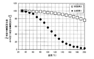
- FIG. 2 is a graph showing the relationship between relative internal quantum efficiency and temperature in the phosphors of Example 3 and Comparative Example 1.
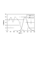
- FIG. 3 is a graph showing an emission spectrum and an excitation spectrum of the phosphor of Example 3.
- the wavelength conversion member according to the present embodiment absorbs ultraviolet light in sunlight and converts it into visible light or infrared light. As a result, visible light or infrared light having high spectral sensitivity is increased, which makes it possible to improve the photoelectric conversion efficiency of the solar cell.
- the wavelength conversion member needs to exhibit high transmittance to visible light and infrared light in which the solar battery cell is a highly sensitive wavelength range. This is because if the transmittance is lowered when the wavelength conversion member is provided, the photoelectric conversion efficiency is lowered due to the decrease of the transmittance than the improvement of the photoelectric conversion efficiency by the wavelength conversion member.
- the wavelength conversion member according to the present embodiment is cerium ion (Ce 3+ ) or A fluoride phosphor activated with europium ion (Eu 2+ ) is provided.
- a fluoride fluorescent substance as a wavelength conversion member, the fall of the transmittance
- the internal quantum efficiency measured at 80 ° C. when the internal quantum efficiency measured at 30 ° C. is 100%, the internal quantum efficiency measured at 80 ° C. is 85% or more.
- the fluoride fluorescent substance excellent in the temperature characteristic since the fluoride fluorescent substance excellent in the temperature characteristic is used, it becomes possible to absorb the ultraviolet light sufficiently even at high temperature in summer to perform wavelength conversion, and to improve the output of the solar cell.
- the fluoride phosphor preferably has an internal quantum efficiency measured at 80 ° C. of 90% or more, and more preferably 95% or more .
- the fluoride fluorescent material needs to have cerium ion (Ce 3+ ) or europium ion (Eu 2+ ) as a luminescent center.
- Ce 3+ and Eu 2+ adopt a mechanism of light absorption and emission based on 4f n ⁇ 4f n -1 5d 1 permissible transition. Therefore, the wavelengths of absorption and emission change depending on the host crystal in which they are activated. Therefore, by selecting an appropriate host crystal with Ce 3+ or Eu 2+ as the emission center, it is possible to convert light in the near ultraviolet to violet region into light in a wavelength range in which the solar battery cell has high sensitivity.
- the matrix of the fluoride phosphor in this embodiment is preferably a fluoride containing an alkaline earth metal and magnesium. That is, the matrix of the fluoride phosphor is preferably a fluoride containing magnesium and at least one element selected from the group consisting of calcium (Ca), strontium (Sr) and barium (Ba). This is preferable because the emission intensity is high and the quantum efficiency tends to be high even at high temperature. The reason why the emission intensity at high temperature is good is presumed to be as follows.
- the crystal structure of the fluoride phosphor is a strong host crystal in which [MgF 6 ] 4- units having an octahedral structure share F to be bonded in large numbers.
- CaF 2 : Eu 2+ is conventionally known as a fluoride fluorescent material having Eu 2+ as a luminescent center.
- the host compound is calcium fluoride (CaF 2 ) and the luminescent center is Eu 2+ .
- CaF 2 : Eu 2+ absorbs ultraviolet light of 300 nm or more and less than 400 nm and emits visible light of about 425 nm, it can be used as a wavelength conversion material for solar cells.
- the refractive index of CaF 2 is 1.43, which is close to the refractive index of the sealing material described later, the transmittance in visible light and infrared light is reduced even if CaF 2 : Eu 2+ is dispersed in the sealing material. It becomes a difficult wavelength conversion member.
- the wavelength conversion member using CaF 2 : Eu 2+ can not sufficiently improve the output of the solar cell.
- the reason why the output of a solar cell can not be improved by such conventional fluoride phosphors is the temperature quenching of the phosphors.
- Thermal quenching is a phenomenon in which the internal quantum efficiency decreases as the temperature of the phosphor increases.
- the temperature of the solar cell may rise to 80 ° C. or more depending on the use environment. Therefore, when the temperature quenching of the phosphor used for the wavelength conversion member is remarkable, the improvement of the efficiency due to the wavelength conversion can not be sufficiently obtained in the use environment where the temperature of the solar cell is high.
- CaF 2 : Eu 2+ can not sufficiently improve the output of the solar cell because the internal quantum efficiency at 80 ° C. decreases to 80% or less of the internal quantum efficiency at 30 ° C.
- all other conventional fluoride phosphors have remarkable temperature quenching, and can not exhibit high internal quantum efficiency even at 80 ° C. or higher. Therefore, the wavelength conversion member which can fully improve the output of a solar cell was not able to be obtained.
- the fluoride phosphor is activated by Ce 3+ or Eu 2+ , and when the internal quantum efficiency measured at 30 ° C. is 100%, the internal quantum measured at 80 ° C. Efficiency is 85% or more. Therefore, wavelength conversion is efficiently performed even in a use environment where the temperature of the solar cell is high, and the output of the solar cell can be improved.
- the inventor knows, there is no reported example of a fluoride phosphor activated with Ce 3+ or Eu 2+ which has such a small temperature quenching, and a fluorescence which achieves both a low refractive index and a good temperature quenching property. Having a body was not a surprise.
- a rare earth ion other than Ce 3+ and Eu 2+ as an emission center is also known.
- the emission center is a rare earth ion other than Ce 3+ and Eu 2+ , it is difficult to obtain an inorganic phosphor that absorbs ultraviolet light having a wavelength of 300 to 400 nm even if the composition of the host crystal is adjusted.
- Ce 3+ and Eu 2+ it is possible to obtain an inorganic phosphor that absorbs ultraviolet light having a wavelength of 300 to 400 nm by adjusting the composition of the host crystal. The main reasons are as follows.
- the rare earth ions from Ce to Yb have electrons in the 4f orbital.
- ions other than Ce 3+ and Eu 2+ generally absorb and emit light by transition in the 4f shell.
- the electrons in the 4f orbital are inside the electrons in the 5s orbital and the 5p orbital and shielded, fluctuation of the energy level due to the influence of the surroundings hardly occurs.
- an inorganic phosphor whose center of emission is ions other than Ce 3+ and Eu 2+
- the change in emission wavelength is small even if the composition of the host crystal is adjusted, and an inorganic phosphor that absorbs ultraviolet light of 300 to 400 nm is used. Hard to get.
- Ce 3+ and Eu 2+ absorb and emit light by the transition between the 5d and 4f shells, ie, the transition between 4f n and 4f n ⁇ 5d.
- the emission wavelength can be adjusted by adjusting the composition of the host crystal in the case of light emission based on the transition from the 4f n ⁇ 1 5d 1 level to the 4f orbital. It is possible to make a big change. This large change in emission wavelength makes it possible to obtain an inorganic phosphor that absorbs ultraviolet light of 300 to 400 nm in the case of an inorganic phosphor having Ce 3+ and Eu 2+ as emission centers.
- the fluoride phosphor is preferably based on the compound represented by the general formula (1).
- the fluoride fluorescent substance excellent in the absorptivity of ultraviolet light, quantum efficiency, and a temperature characteristic can be obtained.
- the alkaline earth metal is preferably at least one element selected from the group consisting of calcium (Ca), strontium (Sr) and barium (Ba).
- M 3 Mg 4 F 14 (1) (Wherein, M is an alkaline earth metal)
- the crystal structure in which a part of the atoms of the host crystal having the composition represented by the general formula (1) is substituted with one of Ce 3+ and Eu 2+ is represented by, for example, the chemical formula (2) or (3) Ru. (M 1-x Ce x ) 3 Mg 4 F 14 (2) (Wherein, M is one or more alkaline earth metals selected from the group consisting of Ca, Sr and Ba, and x satisfies 0 ⁇ x ⁇ 0.3).
- M is one or more alkaline earth metals selected from the group consisting of Ca, Sr and Ba, and y satisfies 0 ⁇ y ⁇ 0.3).
- x is preferably 0.003 ⁇ x ⁇ 0.1, more preferably 0.01 ⁇ x ⁇ 0.1.
- y is preferably 0.003 ⁇ y ⁇ 0.1, more preferably 0.01 ⁇ y ⁇ 0.1.
- the fluoride phosphor may contain an alkali metal. This makes it possible to control the excitation spectrum and the emission spectrum derived from Eu 2+ or Ce 3+ .
- the alkali metal is preferably at least one element selected from the group consisting of lithium (Li), sodium (Na), potassium (K), rubidium (Rb) and cesium (Cs).
- the fluoride phosphor may contain a halogen element other than fluorine as long as the crystal structure of the fluoride phosphor is not impaired. Thereby, it is possible to control the excitation spectrum and the emission spectrum derived from Eu 2+ or Ce 3+ and the refractive index of the phosphor.
- the halogen element is preferably at least one element selected from the group consisting of chlorine (Cl), bromine (Br) and iodine (I).
- the fluoride phosphor may contain manganese ion (Mn 2+ ). As a result, energy transfer from Eu 2+ or Ce 3+ to Mn 2+ occurs, and it becomes possible to emit light on the long wavelength side by causing Mn 2+ to be a luminescent center. Moreover, the fluoride fluorescent substance may contain oxygen in the range which does not impair the crystal structure of the said fluoride fluorescent substance. This makes it possible to control the refractive index of the phosphor.
- the fluoride phosphor may contain a rare earth element other than the element that is the emission center.
- a rare earth element it is possible to include a large number of elements serving as a light emission center, and it is possible to increase the absorptivity of ultraviolet light.
- rare earth elements scandium (Sc), yttrium (Y), lanthanum (La), praseodymium (Pr), neodymium (Nd), promethium (Pm), samarium (Sm), gadolinium (Gd), terbium (Tb) And preferably at least one element selected from the group consisting of dysprosium (Dy), holmium (Ho), erbium (Er), thulium (Tm), ytterbium (Yb) and lutetium (Lu).
- Dy dysprosium
- Ho holmium
- Er erbium
- Tm thulium
- Lu lutetium
- the fluoride fluorescent substance may contain an element other than Mg which can take a hexacoordinated state. By including such an element, it is possible to control the refractive index of the phosphor.
- the element capable of taking a hexacoordinated state is, for example, selected from the group consisting of aluminum (Al), gallium (Ga), scandium (Sc), zirconium (Zr), manganese (Mn) and lutetium (Lu). It is preferable that it is at least one element.
- the fluoride fluorescent material preferably has a crystal structure of the same type as Pb 3 Nb 4 O 12 F 2 . As a result, a phosphor having excellent absorptivity, quantum efficiency and temperature characteristics can be obtained.
- a fluoride fluorescent substance makes a compound represented by Chemical formula (4) a base.
- a phosphor having excellent absorptivity, quantum efficiency and temperature characteristics is obtained.
- the fluoride fluorescent substance is based on the compound represented by the chemical formula (5). This makes it possible to adjust the refractive index of the fluoride phosphor.
- the fluoride phosphor preferably has a center particle diameter (D 50 ) of 0.1 ⁇ m or more and less than 100 ⁇ m, and more preferably 0.3 ⁇ m or more and less than 30 ⁇ m.
- D 50 center particle diameter
- the central particle size of the fluoride fluorescent material can be measured, for example, by a laser diffraction scattering type particle size distribution measuring apparatus.
- the fluoride phosphor preferably has an average particle diameter of 0.1 ⁇ m or more and less than 100 ⁇ m, and more preferably 0.3 ⁇ m or more and less than 30 ⁇ m.
- the average particle diameter of the fluoride fluorescent material is in this range, it is possible to sufficiently absorb ultraviolet light in sunlight and obtain a wavelength conversion member in which a decrease in transmittance of visible light and infrared light is suppressed. It becomes possible.
- the average particle diameter of fluoride fluorescent substance is defined as the average value of the longest axis length in arbitrary 20 or more fluorescent substance particle
- the fluoride phosphor preferably has an emission wavelength of 440 nm or more. Therefore, since the ultraviolet light can be converted to the region where the spectral sensitivity of the solar battery cell is high, the output of the solar battery can be further improved.
- the refractive index of the fluoride phosphor is preferably 1.41 or more and less than 1.57, more preferably 1.44 or more and less than 1.54, and particularly preferably 1.47 or more and less than 1.51. preferable.
- the wavelength conversion member of the present embodiment further includes a sealing material for dispersing the fluoride fluorescent material. That is, in the wavelength conversion member, the fluoride fluorescent material is preferably dispersed in the sealing material. By dispersing the fluoride fluorescent substance in the sealing material, it is possible to efficiently absorb ultraviolet light and to convert the wavelength to visible light or infrared light. Moreover, it becomes easy to shape
- the sealing material for example, at least one resin material selected from the group consisting of ethylene-vinyl acetate copolymer (EVA), polyvinyl butyral (PVB), polyimide, polyethylene, polypropylene, polyethylene terephthalate (PET) is used.
- EVA ethylene-vinyl acetate copolymer
- PVB polyvinyl butyral
- PET polyethylene terephthalate
- the refractive index of these resins is 1.41 or more and less than 1.57.
- the particle diameter of the fluorescent material is several tens of nm in order not to reduce the transmittance of visible light and infrared light.
- the phosphor is miniaturized to a certain extent, or the refractive index of the phosphor is comparable to that of the sealing material.
- the larger the particle size of the phosphor the smaller the defect density in the phosphor, and the less the energy loss at the time of light emission, so the luminous efficiency becomes higher.
- the refractive index of the phosphor be approximately the same as that of the sealing material.
- the refractive index of the fluoride phosphor is preferably 1.41 or more and less than 1.57.
- the inorganic fluorescent substance is used in various light emitting devices, for example, a fluorescent lamp, an electron tube, a plasma display panel (PDP), a white LED, and the like.
- an inorganic fluorescent substance is a compound in which a part of a crystalline compound is partially substituted with an element capable of becoming an ion emitting fluorescence. Ions having such characteristics are called "emission centers" as described above. Then, ions as a luminescent center are introduced into the host as the crystalline compound.
- Examples of the base of the phosphor used for such applications include oxides, nitrides, sulfides, oxynitrides, oxysulfides, acid halides and the like.
- the refractive index of these base compounds is 1.6 or more, which is higher than that of the sealing material. Therefore, in the wavelength conversion member in which the phosphor consisting of such a matrix is dispersed in the sealing material, visible light and infrared light are reflected due to the difference in refractive index between the sealing material and the phosphor, and the transmittance is It has caused deterioration of the photoelectric conversion efficiency due to the decrease.
- the wavelength conversion member of the present embodiment uses a fluoride phosphor as the phosphor.
- a fluoride having a refractive index as low as that of the sealing material is a matrix compound. Therefore, since the refractive index difference between the sealing material and the phosphor is small, the reflection of visible light and infrared light is reduced in the wavelength conversion member, and the deterioration of the photoelectric conversion efficiency due to the reduction of the transmittance is suppressed. Is possible.
- the content of the fluoride fluorescent substance in the sealing material is preferably 0.1 vol% to less than 10 vol%, and more preferably 1 vol% to less than 5 vol%. It becomes possible to obtain the wavelength conversion member which fully absorbed ultraviolet light and suppressed the fall of the transmittance
- the fluoride fluorescent substance in the wavelength conversion member of this embodiment can be manufactured by a well-known method. Specifically, similar to yttrium aluminum garnet (YAG), it can be synthesized using a known solid phase reaction.
- YAG yttrium aluminum garnet
- fluorides of alkaline earth metal elements, fluorides of rare earth elements, and fluorides of magnesium are prepared.
- the raw material powder is prepared to have a stoichiometric composition of the desired compound or a composition close to this, and thoroughly mixed using a mortar, a ball mill or the like.
- the fluoride fluorescent substance of this embodiment can be prepared by baking mixed raw material with an electric furnace etc. using baking containers, such as an alumina crucible. When firing the mixed material, it is preferable to heat the mixture material at a firing temperature of 700 to 1000 ° C. for several hours in the air or in a weak reducing atmosphere.
- additives such as reaction accelerator may be added to the raw material.
- ammonium fluoride (NH 4 F) is preferable because it suppresses the elimination of fluorine.
- the wavelength conversion member of this embodiment can be obtained by mixing with the sealing material the fluorescent substance obtained by making it above, and shape
- the thickness of the wavelength conversion member is not particularly limited, but preferably 200 ⁇ m to 1000 ⁇ m, for example.
- the wavelength conversion member according to the present embodiment includes the fluoride phosphor activated with Ce 3+ or Eu 2+ . And when the fluoride fluorescent substance makes internal quantum efficiency measured at 30 degreeC 100%, internal quantum efficiency measured at 80 degreeC is 85% or more. Further, in the present embodiment, as a result of detailed investigation of a fluoride phosphor activated with Ce 3+ or Eu 2 + , which was conventionally considered to have a large temperature quenching, it was found that some have excellent temperature quenching. It is obtained. Therefore, the wavelength conversion member can efficiently convert the wavelength of ultraviolet light without reducing the transmittance of visible light or infrared light, and the output of the photovoltaic device can be sufficiently improved even at high temperatures. It becomes.
- the photovoltaic device of the present embodiment includes the wavelength conversion member described above. Specifically, as a photovoltaic device according to the present embodiment, a solar cell module 1 as shown in FIG. 1 can be mentioned.
- the solar cell module 1 includes a solar cell 10 as a photoelectric conversion element, a wavelength conversion member 20 disposed on the light receiving surface 13 side of the solar cell 10, and a surface of the wavelength conversion member 20. And a surface protection layer 30 disposed.
- the solar cell module 1 includes a back surface sealing member 40 disposed on the back surface 14 which is a surface opposite to the light receiving surface 13 of the solar battery cell 10 and a back surface protective layer disposed on the back surface of the back surface sealing member 40 And 50. That is, in the solar cell module 1, the surface protection layer 30, the wavelength conversion member 20, the solar cell 10, the back surface sealing member 40, and the back surface protection layer 50 are provided in this order from the top in the figure. .
- the photovoltaic cell 10 absorbs light incident from the light receiving surface 13 of the photovoltaic cell 10 to generate photovoltaic power.
- the solar battery cell 10 is formed using a semiconductor material such as crystalline silicon, gallium arsenide (GaAs), indium phosphide (InP), or the like.
- the solar battery cell 10 is made of, for example, a stack of crystalline silicon and amorphous silicon. Electrodes (not shown) are provided on the light receiving surface 13 of the solar battery cell 10 and the back surface 14 which is the surface opposite to the light receiving surface 13.
- the photovoltaic power generated by the solar battery cell 10 is supplied to the outside through the electrode.
- a wavelength conversion member 20 is disposed on the light receiving surface 13 of the solar battery cell 10. As shown in FIG. 1, the wavelength conversion member 20 includes a sealing material 21 for sealing the light receiving surface 13 of the solar battery cell 10, and a fluoride fluorescent material 25 dispersed in the sealing material 21. The wavelength conversion member 20 prevents the moisture from entering the solar battery cell 10 by the sealing material 21 and improves the strength of the entire solar battery module 1.
- the surface protective layer 30 is provided on the light receiving surface 13 side of the solar battery cell 10, and protects the solar battery cell 10 from the external environment and transmits light to be absorbed by the solar battery cell 10.
- a glass substrate can be used as the surface protective layer 30.
- the surface protective layer 30 may be made of polycarbonate, acrylic resin, polyester, or fluorinated polyethylene in addition to the glass substrate.
- the back surface protective layer 50 is a back sheet provided on the back surface 14 side of the solar battery cell 10.
- the back surface protective layer 50 may be a transparent substrate made of the same glass or plastic as the surface protective layer 30.
- the back surface sealing member 40 is disposed on the back surface 14 of the solar battery cell 10 to prevent the entry of moisture into the solar battery cell 10 and improve the strength of the entire solar battery module 1.
- the back surface sealing member 40 is made of, for example, the same material as the material that can be used for the sealing material 21 of the wavelength conversion member 20.
- the material of the back surface sealing member 40 may be the same as or different from the material of the sealing material 21 of the wavelength conversion member 20.
- a metal foil or the like may be provided between the back surface sealing member 40 and the back surface protective layer 50 so that the light incident from the surface protective layer 30 side is more absorbed by the solar battery cell 10. Thereby, the light reaching the back surface protective layer 50 from the surface protective layer 30 can be reflected in the direction of the solar battery cell 10.
- the solar cell module 1 when the solar cell module 1 is irradiated with ultraviolet light 70 and sunlight including visible light and infrared light 80, the ultraviolet light 70 and visible light and infrared light 80 pass through the surface protection layer 30.
- the light is incident on the wavelength conversion member 20.
- the visible light and the infrared light 80 which are incident on the wavelength conversion member 20 are transmitted through the wavelength conversion member 20 as they are without being substantially converted by the fluoride fluorescent material 25 and are irradiated to the solar battery cell 10.
- the ultraviolet light 70 incident on the wavelength conversion member 20 is converted to visible light and infrared light 80 which are light on the long wavelength side by the fluoride phosphor 25, and then is applied to the solar battery cell 10.
- the solar cell 10 generates a photovoltaic power 90 by the irradiated visible light and infrared light 80, and the photovoltaic power 90 is supplied to the outside of the solar cell module 1 through a terminal (not shown).
- the wavelength conversion member 20 of the present embodiment uses the fluoride fluorescent material 25 which is significantly suppressed in the decrease of the internal quantum efficiency at high temperature and is excellent in the temperature characteristic. Therefore, ultraviolet light can be effectively used without reducing the transmittance in visible light or infrared light, and the output of the solar cell module 1 can be improved even at high temperatures.
- Examples 1 to 16 and Comparative Example 1 (Preparation of phosphor)
- the fluoride phosphors of Examples 1 to 16 and Comparative Example 1 were synthesized using a preparation method utilizing a solid phase reaction, and their characteristics were evaluated.
- the following compound powder was used as a raw material.
- each raw material was weighed at a ratio shown in Table 1.
- the raw materials were sufficiently dry-mixed using a magnetic mortar and a magnetic pestle to obtain sintered raw materials.
- the fired material was transferred to an alumina crucible and fired for 2 hours in a reducing atmosphere (in a 96% nitrogen 4% hydrogen mixed gas atmosphere) at a temperature of 850 ° C. using a tubular atmosphere furnace.
- the fired product was crushed using an alumina mortar and an alumina pestle to obtain the phosphors of Examples 1 to 16.
- each raw material was weighed at a ratio shown in Table 1.
- the raw materials were sufficiently dry-mixed using a magnetic mortar and a magnetic pestle to obtain sintered raw materials.
- the fired material was transferred to an alumina crucible and fired for 2 hours in a reducing atmosphere (in a 96% nitrogen 4% hydrogen mixed gas atmosphere) at a temperature of 1200 ° C. using a tubular atmosphere furnace.
- the fired product was crushed using an alumina mortar and an alumina pestle to obtain a phosphor of Comparative Example 1.
- FIG. 2 is a graph showing relative internal quantum efficiencies at respective temperatures when the internal quantum efficiency at 30 ° C. is 100% for the phosphors of Example 3 and Comparative Example 1.
- the phosphor of Example 3 exhibits high internal quantum efficiency even at high temperature with respect to the phosphor of Comparative Example 1.
- the relative internal quantum efficiency at 80 ° C. of the phosphor of Comparative Example 1 is 80% or less
- the phosphor of Example 3 has a relative internal quantum efficiency of 98% at 80 ° C.
- the phosphor of Example 3 exhibited high relative internal quantum efficiency as high as 96% at 100 ° C. and 89% at 150 ° C. even when the temperature increased.
- each of the phosphors of Examples 1 to 16 emitted light in the visible light region of 400 nm or more.
- all relative internal quantum efficiencies at 80 ° C. to internal quantum efficiencies at 30 ° C. are 95% or more, and temperature characteristics superior to the phosphor of Comparative Example 1 are obtained. Indicated.
- Example 3 The excitation and emission characteristics of the phosphor of Example 3 were evaluated. Specifically, the excitation spectrum and the emission spectrum were measured using a spectrofluorimeter (FP-6500) manufactured by JASCO Corporation. The excitation wavelength at the time of emission spectrum measurement was 350 nm, and the monitor wavelength at the time of excitation spectrum measurement was the emission peak wavelength (458 nm).
- FP-6500 spectrofluorimeter
- the phosphor of Example 3 absorbs ultraviolet light of 300 nm or more and less than 400 nm and shows emission having a peak at 458 nm.
- ⁇ Refractive index> The refractive index of the phosphors of Example 3 and Comparative Example 1 was measured.
- the refractive index of the phosphor was measured by the Becke ray method (based on JIS K7142 B method) using an Abbe refractometer NAR-2T manufactured by Atago Co., Ltd. and a polarizing microscope BH-2 manufactured by Olympus Co., Ltd.
- the measurement conditions are as follows. Immersion liquid: Propylene carbonate (n D 23 1.420) Butyl phthalate (n D 23 1.491) Temperature: 23 ° C
- Light source Na (D line / 589 nm)
- the refractive index of the phosphor of Example 3 was 1.45, and the refractive index of the phosphor of Comparative Example 1 was 1.44.
- the phosphor of Example 3 is in the range of 1.41 or more and less than 1.57, and has a refractive index close to the refractive index of the sealing material.
- Example 17 A wavelength conversion member was produced using the phosphor of Example 3 and ethylene-vinyl acetate copolymer (EVA) as a sealing material. Specifically, first, the phosphor and the ethylene-vinyl acetate copolymer were weighed at the ratio shown in Table 3. As the ethylene-vinyl acetate copolymer, Evaflex (registered trademark) EV450 manufactured by Mitsui-Dupont Polychemical Co., Ltd. was used.
- Evaflex registered trademark
- the mixture was melt-kneaded at a heating temperature of 150 ° C. and a rotational speed of 30 rpm for 30 minutes to obtain a mixture of a phosphor and an ethylene-vinyl acetate copolymer.
- the sheet-like wavelength conversion member with a thickness of 0.6 mm was obtained by heat-pressing the obtained mixture with a heating press at a heating temperature of 150 ° C. and a pressing pressure of 1.5 MPa.
- Comparative Example 2 A wavelength conversion member of this example was obtained in the same manner as in Example 17 except that BAM phosphor (BaMgAl 10 O 17 : Eu 2+ ) was used as the phosphor.
- BAM phosphor BaMgAl 10 O 17 : Eu 2+
- the transmittance of the wavelength conversion members obtained in Example 17 and Comparative Example 2 was measured.
- the measurement of the transmittance was performed using an ultraviolet visible near infrared spectrophotometer UV-2600 manufactured by Shimadzu Corporation.
- the measurement conditions are as follows. Measurement range: 300 to 800 nm Scanning speed: 600 nm / min Sampling interval: 1 nm Slit width: 2 nm
- Table 3 also shows the transmittance of 590 nm light in the wavelength conversion members of Example 17 and Comparative Example 2.
- the refractive index of the BAM phosphor is 1.77.
- the wavelength conversion member of Example 17 using the phosphor of Example 3 exhibited a high transmittance of 81%.
- the wavelength conversion member of Comparative Example 2 using the BAM phosphor had a low transmittance of 42%.
- the refractive index of the phosphor of Example 3 is close to 1.45 and the refractive index of EVA (1.48), and the refractive index of the BAM phosphor is largely different from the refractive index of 1.77 and EVA. It is derived from That is, in the case of the BAM phosphor, since the difference in refractive index with the sealing material is large, the light impinging on the phosphor particles is scattered, and the transmittance is lowered. On the other hand, in the case of the phosphor of Example 3, since the difference in refractive index with the sealing material is small and the scattering of light is suppressed, a high transmittance is shown.
- the wavelength conversion member of the present invention uses a fluoride fluorescent material which is suppressed in lowering of the internal quantum efficiency and is excellent in temperature characteristics. Therefore, ultraviolet light can be effectively used even at high temperatures, and the output of the photovoltaic device can be improved.
Landscapes
- Chemical & Material Sciences (AREA)
- Inorganic Chemistry (AREA)
- Engineering & Computer Science (AREA)
- Materials Engineering (AREA)
- Organic Chemistry (AREA)
- Physics & Mathematics (AREA)
- General Physics & Mathematics (AREA)
- Optics & Photonics (AREA)
- Luminescent Compositions (AREA)
- Photovoltaic Devices (AREA)
Abstract
波長変換部材(20)は、Ce3+又はEu2+で付活されたフッ化物蛍光体(25)を備える。そして、当該フッ化物蛍光体は、30℃で測定した内部量子効率を100%とした場合、80℃で測定した内部量子効率が85%以上である。さらに光起電力デバイスは、上述の波長変換部材を備える。当該波長変換部材は、内部量子効率の低下が抑制され、温度特性に優れたフッ化物蛍光体を用いている。そのため、高温時でも紫外光を有効に利用することができ、光起電力デバイスの出力を向上させることが可能となる。
Description
本発明は、波長変換部材及びそれを用いた光起電力デバイスに関する。詳細には本発明は、光電変換効率を向上させた波長変換部材、及び当該波長変換部材を用いた光起電力デバイスに関する。
一般的に、太陽電池セルは、紫外光の光電変換効率が可視光の光電変換効率よりも低い。例えば、太陽電池セルは、波長300nm以上400nm未満の範囲内にある紫外光では光電変換効率が低く、波長400nm以上1200nm未満の範囲内にある可視光及び赤外光領域では光電変換効率が高い。また、波長380nm未満の範囲内にある紫外光は、太陽電池に損傷を与えやすい、このため、従来の太陽電池では、例えば波長380nm未満の範囲内にある紫外光をフィルターでカットしていた。
しかし、波長380nm未満の範囲内にある紫外光を発電に利用することができれば、太陽電池の光電変換効率の改善が期待される。このため、近年、太陽電池において、波長380nm未満の範囲内にある紫外光をただカットするのではなく、長波長の光に変換して発電に利用することが検討されている。具体的には、紫外光を可視光または赤外光に変換する波長変換層を設ける技術が検討されている。
このような波長変換層に用いられ、紫外光を可視光または赤外光に変換する蛍光体としては、Eu2+を付活したハロゲン化バリウム、具体的にはEu2+を付活したフッ化バリウムが開示されている(例えば、特許文献1参照)。
しかしながら、Eu2+を付活したフッ化バリウムは低温でのみ発光を示し、25℃以上の温度では殆ど発光を示さないため、紫外光を十分に可視光または赤外光に変換することができなかった。つまり、従来のフッ化物蛍光体を用いた波長変換部材では、高温時に太陽電池の出力を向上させることが困難であった。
本発明は、このような従来技術の有する課題に鑑みてなされたものである。そして、本発明の目的は、高温時でも光電変換効率を上げ、太陽電池の出力を向上させることが可能な波長変換部材及びそれを用いた光起電力デバイスを提供することにある。
上記課題を解決するために、本発明の第一の態様に係る波長変換部材は、Ce3+又はEu2+で付活されたフッ化物蛍光体を備える。そして、当該フッ化物蛍光体は、30℃で測定した内部量子効率を100%とした場合、80℃で測定した内部量子効率が85%以上である。
本発明の第二の態様に係る光起電力デバイスは、上述の波長変換部材を備える。
以下、本実施形態に係る波長変換部材及び光起電力デバイスについて詳細に説明する。なお、図面の寸法比率は説明の都合上誇張されており、実際の比率とは異なる場合がある。
[波長変換部材]
本実施形態に係る波長変換部材は、太陽光線における紫外光を吸収した後、可視光または赤外光に変換する。これにより、分光感度が高い可視光または赤外光が増加するため、太陽電池の光電変換効率を向上させることが可能となる。ただ、波長変換部材は、太陽電池セルが高感度な波長域である可視光および赤外光に対して高い透過率を示す必要がある。これは、波長変換部材を設けた場合に透過率が低下してしまうと、波長変換部材による光電変換効率の向上よりも、透過率の低下による光電変換効率の低下を引き起こすためである。
本実施形態に係る波長変換部材は、太陽光線における紫外光を吸収した後、可視光または赤外光に変換する。これにより、分光感度が高い可視光または赤外光が増加するため、太陽電池の光電変換効率を向上させることが可能となる。ただ、波長変換部材は、太陽電池セルが高感度な波長域である可視光および赤外光に対して高い透過率を示す必要がある。これは、波長変換部材を設けた場合に透過率が低下してしまうと、波長変換部材による光電変換効率の向上よりも、透過率の低下による光電変換効率の低下を引き起こすためである。
そのため、波長変換部材による紫外光の吸収効率の向上と可視光および赤外光の透過率低下の抑制とを両立するために、本実施形態に係る波長変換部材は、セリウムイオン(Ce3+)又はユウロピウムイオン(Eu2+)で付活されたフッ化物蛍光体を備えている。波長変換部材としてフッ化物蛍光体を用いることにより、可視光および赤外光の透過率の低下を抑制することができる。
さらに本実施形態の波長変換部材において、フッ化物蛍光体は、30℃で測定した内部量子効率を100%とした場合、80℃で測定した内部量子効率が85%以上である。本実施形態では、温度特性に優れたフッ化物蛍光体を用いているため、夏場の高温時でも十分に紫外光を吸収して波長変換し、太陽電池の出力を向上させることが可能となる。なお、フッ化物蛍光体は、30℃で測定した内部量子効率を100%とした場合、80℃で測定した内部量子効率が90%以上であることが好ましく、95%以上であることがより好ましい。フッ化物蛍光体がこのような高い相対内部量子効率を有することにより、高温時での太陽電池の出力をさらに向上させる波長変換部材を得ることができる。
ここで、フッ化物蛍光体は、セリウムイオン(Ce3+)又はユウロピウムイオン(Eu2+)を発光中心とする必要がある。Ce3+およびEu2+は、4fn⇔4fn-15d1許容遷移に基づく光吸収と発光のメカニズムをとる。そのため、これらが付活される母体結晶によって吸収および発光の波長が変化する。したがって、Ce3+又はEu2+を発光中心とし適切な母体結晶を選択することで、近紫外から紫色領域の光を、太陽電池セルが高感度な波長域の光に変換することが可能となる。なお、上述の4fn⇔4fn-15d1許容遷移において、Ce3+はn=1に該当し、Eu2+はn=7に該当する。
本実施形態におけるフッ化物蛍光体の母体は、アルカリ土類金属及びマグネシウムを含有するフッ化物であることが好ましい。つまり、フッ化物蛍光体の母体は、カルシウム(Ca)、ストロンチウム(Sr)及びバリウム(Ba)からなる群より選ばれる少なくとも一つの元素と、マグネシウムとを含有するフッ化物であることが好ましい。これにより、高温になっても発光強度が高いと共に、量子効率が高くなり易くなるため、好ましい。なお、高温時の発光強度が良好となる理由は次のとおりであると推測される。フッ化物蛍光体の結晶構造は、八面体構造の[MgF6]4-ユニットがFを共有して多数結合した強固な母体結晶になる。そして、この強固な母体結晶の一部が発光中心であるCe3+やEu2+と置換してなる蛍光体は、結晶構造が強固であるため、Ce3+やEu2+が振動し難くなる。発光中心であるCe3+、Eu2+が振動し難いと蛍光体の温度が上昇しても発光が安定して行われるため、アルカリ土類金属元素とマグネシウムとを含むフッ化物からなる蛍光体は、発光強度が良好になると推測される。
ここで、Eu2+を発光中心とするフッ化物蛍光体として、従来、CaF2:Eu2+が知られている。この蛍光体の場合、母体化合物がフッ化カルシウム(CaF2)であり、発光中心がEu2+である。そして、CaF2:Eu2+は300nm以上400nm未満の紫外光を吸収し、約425nmの可視光を放出するため、太陽電池用波長変換材料として使用することができる。また、CaF2の屈折率は1.43と後述する封止材の屈折率と近いため、CaF2:Eu2+を封止材に分散させても可視光および赤外光における透過率を低下させ難い波長変換部材となる。
しかし、CaF2:Eu2+を用いた波長変換部材では、太陽電池の出力を十分に向上させることができない。このような従来のフッ化物蛍光体で太陽電池の出力を向上させることができない理由は、蛍光体の温度消光にある。温度消光とは、蛍光体の温度が上昇するにつれて内部量子効率が低下する現象である。太陽電池は、使用環境によっては80℃以上まで温度が上昇する場合がある。そのため、波長変換部材に用いる蛍光体の温度消光が顕著な場合、太陽電池が高温となる使用環境下では波長変換による効率の向上を十分に得られない。例えば、CaF2:Eu2+は80℃における内部量子効率が30℃における内部量子効率の80%以下まで低下するため、太陽電池の出力を十分に向上させることができなかった。また、従来の他のフッ化物蛍光体は、いずれも温度消光が顕著であり、80℃以上でも高い内部量子効率を示すことができない。そのため、太陽電池の出力を十分に向上させることのできる波長変換部材を得ることができなかった。
これに対し、本実施形態の波長変換部材において、フッ化物蛍光体はCe3+又はEu2+で付活され、30℃で測定した内部量子効率を100%とした場合、80℃で測定した内部量子効率が85%以上である。そのため、太陽電池が高温となる使用環境下でも波長変換が効率的に行われ、太陽電池の出力を向上させることが可能となる。なお、このような温度消光が小さな、Ce3+又はEu2+で付活されたフッ化物蛍光体は本発明者が知る限り報告例はなく、低屈折率と良好な温度消光特性とを両立する蛍光体があることは思いよるものではなかった。
ここで、一般的な無機蛍光体では、発光中心としてCe3+及びEu2+以外の希土類イオンを用いたものも知られている。しかし、発光中心がCe3+及びEu2+以外の希土類イオンであると、母体結晶の組成を調整しても、波長が300~400nmの紫外光を吸収する無機蛍光体を得にくい。ただ、Ce3+及びEu2+の少なくとも一方を含む場合には、母体結晶の組成を調整することで、波長が300~400nmの紫外光を吸収する無機蛍光体を得ることが可能となる。その主な理由としては、以下のことが推測される。
希土類イオンのうちCeからYbまでの希土類イオンは、4f軌道に電子を有する。希土類イオンに由来する光の吸収及び発光は、4f殻内の遷移によるものと、5d殻と4f殻との間の遷移によるものとの二種類がある。
希土類イオンのうちCe3+及びEu2+以外のイオンは、一般的に、4f殻内の遷移により光の吸収及び発光を行う。しかし、この4f殻内の遷移では、4f軌道の電子が5s軌道及び5p軌道の電子の内側にあり遮蔽されているため、周囲の影響によるエネルギー準位の変動が生じにくい。このため、Ce3+及びEu2+以外のイオンを発光中心とする無機蛍光体では、母体結晶の組成を調整しても発光波長の変化は小さく、300~400nmの紫外光を吸収する無機蛍光体を得にくい。
これに対し、Ce3+及びEu2+は、5d殻と4f殻との間の遷移、すなわち4fnと4fn-15dとの間の遷移により光の吸収及び発光を行う。この5d殻と4f殻との間の遷移では、5d軌道が他の軌道から遮蔽されていないため、周囲の影響による5d軌道のエネルギー準位の変動が生じやすい。このため、Ce3+及びEu2+を発光中心とする無機蛍光体では、4fn-15d1準位から4f軌道への遷移に基づく発光の場合、母体結晶の組成を調整することにより発光波長を大きく変化させることが可能になる。この発光波長の大きな変化により、Ce3+及びEu2+を発光中心とする無機蛍光体では、300~400nmの紫外光を吸収する無機蛍光体を得ることが可能になる。
本実施形態の波長変換部材において、フッ化物蛍光体は、一般式(1)で表される化合物を母体とすることが好ましい。それにより、紫外光の吸収率、量子効率及び温度特性に優れたフッ化物蛍光体を得ることができる。なお、一般式(1)において、アルカリ土類金属は、カルシウム(Ca)、ストロンチウム(Sr)及びバリウム(Ba)からなる群より選ばれる少なくとも一つの元素であることが好ましい。
M3Mg4F14 (1)
(式中、Mはアルカリ土類金属である。)
M3Mg4F14 (1)
(式中、Mはアルカリ土類金属である。)
なお、一般式(1)で表される組成を有する母体結晶の原子の一部がCe3+及びEu2+の一方で置換された結晶構造は、例えば、化学式(2)又は(3)で表される。
(M1-xCex)3Mg4F14 (2)
(式中、MはCa、Sr及びBaからなる群より選択される一種以上のアルカリ土類金属であり、xは0<x<0.3を満たす。)
(M1-xCex)3Mg4F14 (2)
(式中、MはCa、Sr及びBaからなる群より選択される一種以上のアルカリ土類金属であり、xは0<x<0.3を満たす。)
(M1-yEuy)3Mg4F14 (3)
(式中、MはCa、Sr及びBaからなる群より選択される一種以上のアルカリ土類金属であり、yは0<y<0.3を満たす。)
(式中、MはCa、Sr及びBaからなる群より選択される一種以上のアルカリ土類金属であり、yは0<y<0.3を満たす。)
化学式(2)において、xは、好ましくは0.003≦x≦0.1、より好ましくは0.01≦x≦0.1である。また、化学式(3)において、yは、好ましくは0.003≦y≦0.1、より好ましくは0.01≦y≦0.1である。
また、フッ化物蛍光体は、アルカリ金属を含んでいてもよい。これにより、Eu2+やCe3+に由来する励起スペクトルおよび発光スペクトルを制御することが可能となる。なお、アルカリ金属としては、リチウム(Li)、ナトリウム(Na)、カリウム(K)、ルビジウム(Rb)及びセシウム(Cs)からなる群より選ばれる少なくとも一つの元素であることが好ましい。
フッ化物蛍光体は、当該フッ化物蛍光体の結晶構造を損ねない範囲でフッ素以外のハロゲン元素を含んでいてもよい。これにより、Eu2+やCe3+に由来する励起スペクトルおよび発光スペクトル、並びに蛍光体の屈折率を制御することが可能である。なお、ハロゲン元素としては、塩素(Cl)、臭素(Br)及びヨウ素(I)からなる群より選ばれる少なくとも一つの元素であることが好ましい。
フッ化物蛍光体は、マンガンイオン(Mn2+)を含んでいてもよい。これにより、Eu2+やCe3+からMn2+へのエネルギー伝達が生じ、Mn2+が発光中心となって長波長側で発光することが可能となる。また、フッ化物蛍光体は、当該フッ化物蛍光体の結晶構造を損ねない範囲で酸素を含んでいてもよい。これにより蛍光体の屈折率を制御することが可能となる。
さらにフッ化物蛍光体は、発光中心となる元素以外の希土類元素を含んでもよい。希土類元素を含むことで、発光中心となる元素を多く含むことができ、紫外光の吸収率を高めることが可能となる。なお、希土類元素としては、スカンジウム(Sc)、イットリウム(Y)、ランタン(La)、プラセオジム(Pr)、ネオジム(Nd)、プロメチウム(Pm)、サマリウム(Sm)、ガドリニウム(Gd)、テルビウム(Tb)、ジスプロシウム(Dy)、ホルミウム(Ho)、エルビウム(Er)、ツリウム(Tm)、イッテルビウム(Yb)、ルテチウム(Lu)からなる群より選ばれる少なくとも一つの元素であることが好ましい。
フッ化物蛍光体は、Mg以外の六配位の状態を取り得る元素を含んでいてもよい。このような元素を含むことで、蛍光体の屈折率を制御することが可能である。なお、六配位の状態を取り得る元素としては、例えばアルミニウム(Al)、ガリウム(Ga)、スカンジウム(Sc)、ジルコニウム(Zr)、マンガン(Mn)及びルテチウム(Lu)からなる群より選ばれる少なくとも一つの元素であることが好ましい。
フッ化物蛍光体は、Pb3Nb4O12F2と同型の結晶構造であることが好ましい。これにより、吸収率、量子効率及び温度特性に優れた蛍光体となることができる。
また、フッ化物蛍光体は、化学式(4)で表される化合物を母体とすることが好ましい。これにより、吸収率、量子効率及び温度特性の優れた蛍光体となる。また、フッ化物蛍光体の屈折率を調整することが可能となる。
Ba2(Ca1-xSrx)Mg4F14 (4)
(式中、0≦x≦1である。)
Ba2(Ca1-xSrx)Mg4F14 (4)
(式中、0≦x≦1である。)
フッ化物蛍光体は、化学式(5)で表される化合物を母体とすることも好ましい。これにより、フッ化物蛍光体の屈折率を調整することが可能となる。
Ba2+y(Ca1-xSrx)1-yMg4F14 (5)
(式中、0≦x≦1、0≦y≦1である。)
Ba2+y(Ca1-xSrx)1-yMg4F14 (5)
(式中、0≦x≦1、0≦y≦1である。)
本実施形態の波長変換部材において、フッ化物蛍光体は、中心粒径(D50)が0.1μm以上100μm未満であることが好ましく、0.3μm以上30μm未満であることがより好ましい。蛍光体の中心粒径がこの範囲内であることにより、太陽光線中の紫外光を十分に吸収し、可視光および赤外光の透過率の低下を抑制した波長変換部材を得ることが可能となる。なお、フッ化物蛍光体の中心粒径は、例えば、レーザー回折散乱式粒度分布測定装置により測定することができる。
また、フッ化物蛍光体は、平均粒子径が0.1μm以上100μm未満であることが好ましく、0.3μm以上30μm未満であることがより好ましい。フッ化物蛍光体の平均粒子径がこの範囲内であることにより、太陽光線中の紫外光を十分に吸収し、可視光および赤外光の透過率の低下を抑制した波長変換部材を得ることが可能となる。なお、フッ化物蛍光体の平均粒子径は、走査型電子顕微鏡で観察した、任意の20個以上の蛍光体粒子における最長軸長の平均値と定義する。
フッ化物蛍光体は、発光波長が440nm以上であることが好ましい。これにより、紫外光を太陽電池セルの分光感度が高い領域に変換できるため、太陽電池の出力をより大きく向上させることが可能となる。
フッ化物蛍光体の屈折率は1.41以上1.57未満であることが好ましく、1.44以上1.54未満であることがより好ましく、1.47以上1.51未満であることが特に好ましい。これにより、後述するようにフッ化物蛍光体を封止材に分散させた場合、可視光および赤外光の透過率の低下を抑制することが可能となる。
本実施形態の波長変換部材は、フッ化物蛍光体を分散させる封止材をさらに備えることが好ましい。つまり、波長変換部材において、フッ化物蛍光体は封止材中に分散されていることが好ましい。フッ化物蛍光体を封止材中に分散させることにより、紫外光を効率的に吸収し、可視光または赤外光に波長変換することが可能となる。また、波長変換部材をシート状やフィルム状に成形しやすくなり、太陽電池セル上に容易に配置することが可能となる。
封止材としては、例えば、エチレン-酢酸ビニル共重合体(EVA)、ポリビニルブチラール(PVB)、ポリイミド、ポリエチレン、ポリプロピレン、ポリエチレンテレフタレート(PET)からなる群より選ばれる少なくとも一つの樹脂材料を用いることができる。なお、これらの樹脂の屈折率は1.41以上1.57未満である。
ここで、波長変換部材がフッ化物蛍光体を封止材中に分散させた構成である場合、可視光および赤外光の透過率を低下させないためには、蛍光体の粒子径が数十nm程度まで微細化されているか、蛍光体の屈折率が封止材と同程度であることが好ましい。ただ、蛍光体の粒子径が大きい方が蛍光体中の欠陥密度が小さくなり、発光時のエネルギー損失が少なくなるため、発光効率が高くなる。したがって、可視光および赤外光の透過率を低下させないために、本実施形態の波長変換部材は、蛍光体の屈折率が封止材と同程度であることが好ましい。具体的には、上述のように、フッ化物蛍光体の屈折率は1.41以上1.57未満であることが好ましい。
ここで、無機蛍光体は様々な発光装置に用いられ、例えば蛍光灯や電子管、プラズマディスプレイパネル(PDP)、白色LEDなどに用いられている。一般に無機蛍光体は結晶質の化合物の一部を、蛍光を放つイオンとなり得る元素で部分置換した化合物である。このような特性を持つイオンは、上述のように「発光中心」と呼ばれる。そして、当該結晶質の化合物としての母体に、発光中心としてのイオンが導入されている。このような用途に用いられる蛍光体の母体としては、酸化物や窒化物、硫化物、酸窒化物、酸硫化物、酸ハロゲン化物などが挙げられる。一般にこれらの母体となる化合物の屈折率は1.6以上であり、封止材に比べて高い。そのため、このような母体からなる蛍光体を封止材中に分散させた波長変換部材は、封止材と蛍光体との屈折率の違いにより可視光及び赤外光が反射し、透過率の低下による光電変換効率の悪化を引き起こしていた。
これに対し、本実施形態の波長変換部材は、蛍光体としてフッ化物蛍光体を用いている。フッ化物蛍光体は、封止材と同程度の低屈折率であるフッ化物が母体化合物である。そのため、封止材と蛍光体との間の屈折率差が小さいことから、波長変換部材において可視光及び赤外光の反射が減少し、透過率の低下による光電変換効率の悪化を抑制することが可能となる。
本実施形態の波長変換部材において、封止材中のフッ化物蛍光体の含有量は0.1vol%以上10vol%未満であることが好ましく、1vol%以上5vol%未満であることがより好ましい。これにより紫外光を十分に吸収し、可視光および赤外光の透過率の低下を抑制した波長変換部材を得ることが可能となる。
本実施形態の波長変換部材におけるフッ化物蛍光体は、公知の手法により製造することができる。具体的には、イットリウム・アルミニウム・ガーネット(YAG)と同様に、公知の固相反応を用いて合成することができる。
具体的には、まず、アルカリ土類金属元素のフッ化物、希土類元素のフッ化物、マグネシウムのフッ化物を準備する。次に、所望の化合物の化学量論的組成又はこれに近い組成となるように原料粉末を調合し、乳鉢やボールミルなどを用いて十分に混合する。その後、アルミナるつぼなどの焼成容器を用いて、電気炉などにより混合原料を焼成することで、本実施形態のフッ化物蛍光体を調製することができる。なお、混合原料を焼成する際には、大気中又は弱還元雰囲気下、700~1000℃の焼成温度にて数時間加熱することが好ましい。また、原料に反応促進剤などの添加剤を加えてもよい。例えばフッ化アンモニウム(NH4F)はフッ素の脱離を抑制するため、好ましい。
そして、本実施形態の波長変換部材は、上述のようにして得られた蛍光体を封止材と混合し、シート状、フィルム状、板状などの形態に成形することで得ることができる。なお、波長変換部材の厚みは特に限定されないが、例えば200μm~1000μmとすることが好ましい。
このように、本実施形態に係る波長変換部材は、Ce3+又はEu2+で付活されたフッ化物蛍光体を備える。そして、フッ化物蛍光体は、30℃で測定した内部量子効率を100%とした場合、80℃で測定した内部量子効率が85%以上である。そして、本実施形態は、従来、温度消光が大きいと思われていたCe3+又はEu2+で付活されたフッ化物蛍光体を詳しく調査した結果、温度消光に優れるものがあることが判り、なし得たものである。そのため、波長変換部材において可視光または赤外光の透過率を低下させずに紫外光を効率的に波長変換することができ、高温時でも光起電力デバイスの出力を十分に向上させることが可能となる。
[光起電力デバイス]
次に、本実施形態に係る光起電力デバイスについて説明する。本実施形態の光起電力デバイスは、上述の波長変換部材を備えている。具体的には、本実施形態に係る光起電力デバイスとしては、図1に示すような太陽電池モジュール1を挙げることができる。
次に、本実施形態に係る光起電力デバイスについて説明する。本実施形態の光起電力デバイスは、上述の波長変換部材を備えている。具体的には、本実施形態に係る光起電力デバイスとしては、図1に示すような太陽電池モジュール1を挙げることができる。
図1に示すように、太陽電池モジュール1は、光電変換素子としての太陽電池セル10と、太陽電池セル10の受光面13側に配置された波長変換部材20と、波長変換部材20の表面に配置された表面保護層30とを備える。また、太陽電池モジュール1は、太陽電池セル10の受光面13と反対側の面である裏面14に配置された裏面封止部材40と、裏面封止部材40の裏面に配置された裏面保護層50とを備える。すなわち、太陽電池モジュール1は、図中上から、表面保護層30、波長変換部材20、太陽電池セル10、裏面封止部材40及び裏面保護層50がこの順番で設けられた構成となっている。
太陽電池セル10は、太陽電池セル10の受光面13から入射される光を吸収して光起電力を発生する。太陽電池セル10は、例えば結晶系シリコン、ガリウム砒素(GaAs)、インジウム燐(InP)等の半導体材料を用いて形成される。具体的には、太陽電池セル10は、例えば、結晶シリコンとアモルファスシリコンとが積層されたものからなる。太陽電池セル10の受光面13と、受光面13と反対側の面である裏面14とには、図示しない電極が設けられる。太陽電池セル10で発生した光起電力は、電極を介して外部に供給される。
太陽電池セル10の受光面13には、波長変換部材20が配置される。図1に示すように、波長変換部材20は、太陽電池セル10の受光面13を封止する封止材21と、封止材21中に分散されるフッ化物蛍光体25とを含む。波長変換部材20は、封止材21により、太陽電池セル10への水分の浸入を防ぎ、太陽電池モジュール1全体の強度を向上させる。
表面保護層30は、太陽電池セル10の受光面13側に設けられ、太陽電池セル10を外部環境から保護すると共に、太陽電池セル10に吸収させるべき光を透過する。表面保護層30は、例えばガラス基板を用いることができる。なお、表面保護層30は、ガラス基板の他に、ポリカーボネート、アクリル樹脂、ポリエステル、フッ化ポリエチレンであってもよい。裏面保護層50は、太陽電池セル10の裏面14側に設けられるバックシートである。裏面保護層50は、表面保護層30と同じガラスやプラスチック等の透明基板としてもよい。
裏面封止部材40は、太陽電池セル10の裏面14に配置され、太陽電池セル10への水分の浸入を防ぎ、太陽電池モジュール1全体の強度を向上させる。裏面封止部材40は、例えば、波長変換部材20の封止材21で用いられ得る材料と同じ材料からなる。裏面封止部材40の材質は、波長変換部材20の封止材21の材質と同じであってもよいし異なっていてもよい。
また、表面保護層30側から入射した光が太陽電池セル10により多く吸収されるように、裏面封止部材40と裏面保護層50の間に金属箔などを設けてもよい。これにより、表面保護層30から裏面保護層50に達した光を太陽電池セル10の方向に反射させることができる。
そして、太陽電池モジュール1に、紫外光70や、可視光及び赤外光80を含む太陽光が照射されると、紫外光70や可視光及び赤外光80は、表面保護層30を透過して、波長変換部材20に入射される。波長変換部材20に入射された可視光及び赤外光80は、実質的にフッ化物蛍光体25で変換されることなく、そのまま波長変換部材20を透過して太陽電池セル10に照射される。一方、波長変換部材20に入射された紫外光70は、フッ化物蛍光体25で長波長側の光である可視光及び赤外光80に変換された後、太陽電池セル10に照射される。太陽電池セル10は、照射された可視光及び赤外光80により光起電力90を生じ、光起電力90は図示しない端子を介して太陽電池モジュール1の外部に供給される。
上述のように、本実施形態の波長変換部材20は、高温での内部量子効率の低下が大幅に抑制され、温度特性に優れたフッ化物蛍光体25を用いている。そのため、可視光または赤外光における透過率を低下させずに紫外光を有効に利用することができ、高温時でも太陽電池モジュール1の出力を向上させることが可能となる。
以下、本実施形態を実施例及び比較例によりさらに詳細に説明するが、本実施形態はこれら実施例に限定されるものではない。
[実施例1乃至16及び比較例1]
(蛍光体の調製)
固相反応を利用する調製手法を用いて、実施例1乃至16及び比較例1のフッ化物蛍光体を合成し、その特性を評価した。なお、本実施例及び比較例では、以下の化合物粉末を原料として使用した。
(蛍光体の調製)
固相反応を利用する調製手法を用いて、実施例1乃至16及び比較例1のフッ化物蛍光体を合成し、その特性を評価した。なお、本実施例及び比較例では、以下の化合物粉末を原料として使用した。
フッ化バリウム(BaF2):純度3N、和光純薬工業株式会社製
フッ化ストロンチウム(SrF2):純度2N5、和光純薬工業株式会社製
フッ化カルシウム(CaF2):純度3N、株式会社高純度化学研究所製
フッ化マグネシウム(MgF2):純度2N、和光純薬工業株式会社製
フッ化ユウロピウム(EuF3):純度3N、和光純薬工業株式会社製
フッ化ストロンチウム(SrF2):純度2N5、和光純薬工業株式会社製
フッ化カルシウム(CaF2):純度3N、株式会社高純度化学研究所製
フッ化マグネシウム(MgF2):純度2N、和光純薬工業株式会社製
フッ化ユウロピウム(EuF3):純度3N、和光純薬工業株式会社製
実施例1乃至16に関し、まず表1に示す割合で各原料を秤量した。次に磁性乳鉢および磁性乳棒を用いて原料を十分に乾式混合し、焼成原料とした。その後、焼成原料をアルミナるつぼに移し、管状雰囲気炉を用いて850℃の温度で、還元雰囲気中(96%窒素4%水素混合ガス雰囲気中)で2時間焼成した。その後、焼成物をアルミナ乳鉢およびアルミナ乳棒を用いて解砕処理することで、実施例1乃至16の各蛍光体を得た。
なお、得られた実施例1乃至16の蛍光体に紫外線(波長365nm)を照射したところ、いずれも青色の蛍光が目視観察された。
次に、比較例1に関し、まず表1に示す割合で各原料を秤量した。次に磁性乳鉢および磁性乳棒を用いて原料を十分に乾式混合し、焼成原料とした。その後、焼成原料をアルミナるつぼに移し、管状雰囲気炉を用いて1200℃の温度で、還元雰囲気中(96%窒素4%水素混合ガス雰囲気中)で2時間焼成した。その後、焼成物をアルミナ乳鉢およびアルミナ乳棒を用いて解砕処理することで、比較例1の蛍光体を得た。
なお、得られた比較例1の蛍光体に紫外線(波長365nm)を照射したところ、青紫色の蛍光が目視観察された。

(評価)
<内部量子効率>
実施例1乃至16及び比較例1で得られた蛍光体の内部量子効率を測定した。蛍光体の量子効率の測定は、大塚電子株式会社製の量子効率測定システムQE-1100を用いて行った。測定および解析条件は以下の通りである。
励起波長:350nm
積算回数:30回
露光時間:オート
測定温度範囲:30℃~200℃
測定温度ステップ:10℃
励起光波長範囲:±20nm
蛍光波長範囲:370nm~800nm
<内部量子効率>
実施例1乃至16及び比較例1で得られた蛍光体の内部量子効率を測定した。蛍光体の量子効率の測定は、大塚電子株式会社製の量子効率測定システムQE-1100を用いて行った。測定および解析条件は以下の通りである。
励起波長:350nm
積算回数:30回
露光時間:オート
測定温度範囲:30℃~200℃
測定温度ステップ:10℃
励起光波長範囲:±20nm
蛍光波長範囲:370nm~800nm
図2は、実施例3と比較例1の蛍光体に関し、30℃での内部量子効率を100%とした際の、各温度における相対内部量子効率を示すグラフである。図2に示すように、実施例3の蛍光体は比較例1の蛍光体に対して高温時でも高い内部量子効率を示していることが分かる。具体的には、比較例1の蛍光体は80℃での相対内部量子効率が80%以下であるのに対し、実施例3の蛍光体は80℃での相対内部量子効率が98%であった。さらに、実施例3の蛍光体は温度が上昇した場合でも、100℃で96%、150℃で89%と高い相対内部量子効率を示した。
表2では、実施例1乃至16及び比較例1の各蛍光体における、30℃での内部量子効率に対する80℃での相対内部量子効率([80℃での内部量子効率]/[30℃での内部量子効率]×100)を示す。また、表2では、実施例1乃至16及び比較例1の各蛍光体を350nmで励起した際の発光ピーク波長も合わせて示す。
表2に示すように、実施例1乃至16の各蛍光体は、いずれも400nm以上の可視光領域に発光を示した。また、実施例1乃至16の各蛍光体は、30℃での内部量子効率に対する80℃での相対内部量子効率が全て95%以上であり、比較例1の蛍光体よりも優れた温度特性を示した。

<励起特性及び発光特性>
実施例3の蛍光体に関し、励起および発光特性を評価した。具体的には、日本分光株式会社製の分光蛍光光度計(FP-6500)を用いて励起スペクトルおよび発光スペクトルを測定した。なお、発光スペクトル測定時の励起波長は350nmとし、励起スペクトル測定時のモニタ波長については発光ピーク波長(458nm)とした。
実施例3の蛍光体に関し、励起および発光特性を評価した。具体的には、日本分光株式会社製の分光蛍光光度計(FP-6500)を用いて励起スペクトルおよび発光スペクトルを測定した。なお、発光スペクトル測定時の励起波長は350nmとし、励起スペクトル測定時のモニタ波長については発光ピーク波長(458nm)とした。
図3に示すように、実施例3の蛍光体は300nm以上400nm未満の紫外光を吸収し、458nmにピークを有する発光を示すことが分かる。
<屈折率>
実施例3及び比較例1の蛍光体について、屈折率を測定した。蛍光体の屈折率は、株式会社アタゴ製のアッベ屈折率計NAR-2Tおよびオリンパス株式会社製の偏光顕微鏡BH-2を用いて、ベッケ線法(JIS K7142 B法準拠)によって測定した。測定条件は、以下の通りである。
浸液:炭酸プロピレン(nD 23 1.420)
フタル酸ブチル(nD 23 1.491)
温度:23℃
光源:Na(D線/589nm)
実施例3及び比較例1の蛍光体について、屈折率を測定した。蛍光体の屈折率は、株式会社アタゴ製のアッベ屈折率計NAR-2Tおよびオリンパス株式会社製の偏光顕微鏡BH-2を用いて、ベッケ線法(JIS K7142 B法準拠)によって測定した。測定条件は、以下の通りである。
浸液:炭酸プロピレン(nD 23 1.420)
フタル酸ブチル(nD 23 1.491)
温度:23℃
光源:Na(D線/589nm)
測定の結果、実施例3の蛍光体の屈折率は1.45であり、比較例1の蛍光体の屈折率は1.44であった。このように、実施例3の蛍光体は1.41以上1.57未満の範囲であり、封止材の屈折率と近い屈折率を有していることが分かる。
[実施例17]
実施例3の蛍光体と封止材としてエチレン-酢酸ビニル共重合体(EVA)とを用いて波長変換部材を作製した。具体的には、まず表3に示す割合で蛍光体とエチレン-酢酸ビニル共重合体を秤量した。エチレン-酢酸ビニル共重合体としては、三井・デュポン ポリケミカル株式会社製エバフレックス(登録商標)EV450を使用した。
実施例3の蛍光体と封止材としてエチレン-酢酸ビニル共重合体(EVA)とを用いて波長変換部材を作製した。具体的には、まず表3に示す割合で蛍光体とエチレン-酢酸ビニル共重合体を秤量した。エチレン-酢酸ビニル共重合体としては、三井・デュポン ポリケミカル株式会社製エバフレックス(登録商標)EV450を使用した。
次に、東洋精機株式会社製のプラストミルを用いて、加熱温度150℃、回転数30rpm、30分で溶融混錬することにより、蛍光体とエチレン-酢酸ビニル共重合体との混合物を得た。そして、得られた混合物を加熱プレス機で加熱温度150℃、プレス圧1.5MPaで加熱プレスを行うことにより、厚さ0.6mmのシート状の波長変換部材を得た。
[比較例2]
蛍光体として、BAM蛍光体(BaMgAl10O17:Eu2+)を用いた以外は実施例17と同様にして、本例の波長変換部材を得た。
蛍光体として、BAM蛍光体(BaMgAl10O17:Eu2+)を用いた以外は実施例17と同様にして、本例の波長変換部材を得た。

実施例17及び比較例2で得られた波長変換部材について、透過率を測定した。透過率の測定は、株式会社島津製作所製の紫外可視近赤外分光光度計UV-2600を用いて行った。測定条件は以下の通りである。
測定範囲:300~800nm
スキャンスピード:600nm/min
サンプリング間隔:1nm
スリット幅:2nm
光源切替波長:340nm
光源(300~340nm):重水素ランプ
光源(340~800nm):タングステンハロゲンランプ
測定範囲:300~800nm
スキャンスピード:600nm/min
サンプリング間隔:1nm
スリット幅:2nm
光源切替波長:340nm
光源(300~340nm):重水素ランプ
光源(340~800nm):タングステンハロゲンランプ
表3では、実施例17及び比較例2の波長変換部材における、590nmの光の透過率を合わせて示している。なお、BAM蛍光体の屈折率は1.77である。
表3に示すように、実施例3の蛍光体を用いた実施例17の波長変換部材は、透過率が81%と高い値を示した。一方、BAM蛍光体を用いた比較例2の波長変換部材は、透過率が42%と低い値となった。これは実施例3の蛍光体の屈折率が1.45とEVAの屈折率(1.48)に近似しており、BAM蛍光体の屈折率が1.77とEVAの屈折率と大きく異なっていることに由来する。つまり、BAM蛍光体の場合には封止材との屈折率差が大きいため、蛍光体粒子に当たった光が散乱してしまい、透過率が低下した。一方で実施例3の蛍光体の場合には封止材との屈折率差が小さく、光の散乱が抑制されるため、高い透過率を示した。
特願2015-022869号(出願日:2015年2月9日)の全内容は、ここに援用される。
以上、実施例に沿って本発明の内容を説明したが、本発明はこれらの記載に限定されるものではなく、種々の変形及び改良が可能であることは、当業者には自明である。
本発明の波長変換部材は、内部量子効率の低下が抑制され、温度特性に優れたフッ化物蛍光体を用いている。そのため、高温時でも紫外光を有効に利用することができ、光起電力デバイスの出力を向上させることが可能となる。
1 太陽電池モジュール(光起電力デバイス)
20 波長変換部材
21 封止材
25 フッ化物蛍光体
20 波長変換部材
21 封止材
25 フッ化物蛍光体
Claims (6)
- Ce3+又はEu2+で付活されたフッ化物蛍光体を備え、
前記フッ化物蛍光体は、30℃で測定した内部量子効率を100%とした場合、80℃で測定した内部量子効率が85%以上であることを特徴とする波長変換部材。 - 前記フッ化物蛍光体の母体は、アルカリ土類金属及びマグネシウムを含有するフッ化物であることを特徴とする請求項1に記載の波長変換部材。
- 前記フッ化物蛍光体は、一般式:M3Mg4F14(式中、Mはアルカリ土類金属)で表される化合物を母体とすることを特徴とする請求項1又は2に記載の波長変換部材。
- 前記フッ化物蛍光体の屈折率が1.41以上1.57未満であることを特徴とする請求項1乃至3のいずれか一項に記載の波長変換部材。
- 前記フッ化物蛍光体を分散させる封止材をさらに備えることを特徴とする請求項1乃至4のいずれか一項に記載の波長変換部材。
- 請求項1乃至5のいずれか一項に記載の波長変換部材を備えることを特徴とする光起電力デバイス。
Priority Applications (3)
| Application Number | Priority Date | Filing Date | Title |
|---|---|---|---|
| CN201580074969.6A CN107209297A (zh) | 2015-02-09 | 2015-12-16 | 波长转换部件以及使用了该波长转换部件的光伏器件 |
| US15/547,450 US20180026150A1 (en) | 2015-02-09 | 2015-12-16 | Wavelength conversion member and photovoltaic device using same |
| EP15881899.7A EP3260895A4 (en) | 2015-02-09 | 2015-12-16 | Wavelength conversion member and photovoltaic device using same |
Applications Claiming Priority (2)
| Application Number | Priority Date | Filing Date | Title |
|---|---|---|---|
| JP2015022869A JP2016145295A (ja) | 2015-02-09 | 2015-02-09 | 波長変換部材及びそれを用いた光起電力デバイス |
| JP2015-022869 | 2015-02-09 |
Publications (1)
| Publication Number | Publication Date |
|---|---|
| WO2016129023A1 true WO2016129023A1 (ja) | 2016-08-18 |
Family
ID=56614434
Family Applications (1)
| Application Number | Title | Priority Date | Filing Date |
|---|---|---|---|
| PCT/JP2015/006268 Ceased WO2016129023A1 (ja) | 2015-02-09 | 2015-12-16 | 波長変換部材及びそれを用いた光起電力デバイス |
Country Status (5)
| Country | Link |
|---|---|
| US (1) | US20180026150A1 (ja) |
| EP (1) | EP3260895A4 (ja) |
| JP (1) | JP2016145295A (ja) |
| CN (1) | CN107209297A (ja) |
| WO (1) | WO2016129023A1 (ja) |
Cited By (1)
| Publication number | Priority date | Publication date | Assignee | Title |
|---|---|---|---|---|
| WO2018055849A1 (ja) * | 2016-09-26 | 2018-03-29 | パナソニックIpマネジメント株式会社 | 蛍光体、並びにそれを用いた波長変換部材及び電子装置 |
Families Citing this family (3)
| Publication number | Priority date | Publication date | Assignee | Title |
|---|---|---|---|---|
| CN108963000A (zh) * | 2018-06-27 | 2018-12-07 | 张家港康得新光电材料有限公司 | 一种光伏板 |
| US11862559B2 (en) | 2020-07-31 | 2024-01-02 | Taiwan Semiconductor Manufacturing Co., Ltd. | Semiconductor structures and methods of forming the same |
| JP7686608B2 (ja) | 2022-10-28 | 2025-06-02 | ソフトバンク株式会社 | 光電変換装置及び飛行体 |
Citations (3)
| Publication number | Priority date | Publication date | Assignee | Title |
|---|---|---|---|---|
| US4112328A (en) * | 1975-09-22 | 1978-09-05 | Gte Sylvania Incorporated | Barium magnesium fluoride phosphors and lamps and X-ray screens embodying same |
| JP2007027423A (ja) * | 2005-07-15 | 2007-02-01 | Univ Of Electro-Communications | 太陽電池素子及び太陽光発電装置 |
| JP2013087243A (ja) * | 2011-10-20 | 2013-05-13 | Hitachi Chemical Co Ltd | 球状蛍光体、波長変換型太陽電池封止材、太陽電池モジュール及びこれらの製造方法 |
-
2015
- 2015-02-09 JP JP2015022869A patent/JP2016145295A/ja active Pending
- 2015-12-16 US US15/547,450 patent/US20180026150A1/en not_active Abandoned
- 2015-12-16 CN CN201580074969.6A patent/CN107209297A/zh active Pending
- 2015-12-16 EP EP15881899.7A patent/EP3260895A4/en not_active Withdrawn
- 2015-12-16 WO PCT/JP2015/006268 patent/WO2016129023A1/ja not_active Ceased
Patent Citations (3)
| Publication number | Priority date | Publication date | Assignee | Title |
|---|---|---|---|---|
| US4112328A (en) * | 1975-09-22 | 1978-09-05 | Gte Sylvania Incorporated | Barium magnesium fluoride phosphors and lamps and X-ray screens embodying same |
| JP2007027423A (ja) * | 2005-07-15 | 2007-02-01 | Univ Of Electro-Communications | 太陽電池素子及び太陽光発電装置 |
| JP2013087243A (ja) * | 2011-10-20 | 2013-05-13 | Hitachi Chemical Co Ltd | 球状蛍光体、波長変換型太陽電池封止材、太陽電池モジュール及びこれらの製造方法 |
Non-Patent Citations (1)
| Title |
|---|
| See also references of EP3260895A4 * |
Cited By (1)
| Publication number | Priority date | Publication date | Assignee | Title |
|---|---|---|---|---|
| WO2018055849A1 (ja) * | 2016-09-26 | 2018-03-29 | パナソニックIpマネジメント株式会社 | 蛍光体、並びにそれを用いた波長変換部材及び電子装置 |
Also Published As
| Publication number | Publication date |
|---|---|
| EP3260895A1 (en) | 2017-12-27 |
| CN107209297A (zh) | 2017-09-26 |
| US20180026150A1 (en) | 2018-01-25 |
| EP3260895A4 (en) | 2018-03-14 |
| JP2016145295A (ja) | 2016-08-12 |
Similar Documents
| Publication | Publication Date | Title |
|---|---|---|
| EP3438229B1 (en) | Fluorescent body, light-emitting device, illuminating apparatus, and image display apparatus | |
| US6255670B1 (en) | Phosphors for light generation from light emitting semiconductors | |
| JP5944508B2 (ja) | オプトエレクトロニクス部品 | |
| US8674388B2 (en) | Phosphor, method of manufacturing the same, and light-emitting device | |
| JP5592602B2 (ja) | 蛍光体およびそれを用いた発光装置 | |
| US9359551B2 (en) | Phosphor, manufacture thereof; light-emitting device, and image display device utilizing phosphor | |
| EP2280054B1 (en) | Europium doped halogen-silicate phosphor and light emitting device | |
| US20110234118A1 (en) | Complex Crystal Phosphor, Light Emitting Device, Surface Light Source Apparatus, Display Apparatus, and Lighting Device | |
| JP2008545048A (ja) | アルミネート系青色蛍光体 | |
| JP2008545048A6 (ja) | アルミネート系青色蛍光体 | |
| JPWO2006106883A1 (ja) | 蛍光体、蛍光体シートおよびその製造方法、並びに当該蛍光体を用いた発光装置 | |
| JP6115432B2 (ja) | 複合波長変換粒子及び複合波長変換粒子含有樹脂組成物並びに発光装置 | |
| Dutta et al. | Inorganic phosphor materials for solid state white light generation | |
| EP3480280B1 (en) | Fluorophore and light-emitting device | |
| WO2016129023A1 (ja) | 波長変換部材及びそれを用いた光起電力デバイス | |
| JP6123619B2 (ja) | 複合波長変換粒子及び複合波長変換粒子含有樹脂組成物並びに発光装置 | |
| EP2687575B1 (en) | Phosphor based on caxsryeuzsi2n2o2 and light emitting device comprising the same | |
| US20180016496A1 (en) | Phosphor, wavelength conversion member, and photovoltaic device | |
| JP2014194019A (ja) | 照明システム | |
| WO2018055849A1 (ja) | 蛍光体、並びにそれを用いた波長変換部材及び電子装置 | |
| JP2011506655A5 (ja) | ||
| JP2018180159A (ja) | 波長変換フィルタ及び太陽電池モジュール | |
| JP2017132844A (ja) | フッ化物蛍光体、波長変換部材及び光電変換装置 | |
| US10174245B2 (en) | Method for producing a luminescent material, luminescent material and optoelectronic component | |
| JP2013110155A (ja) | 発光装置 |
Legal Events
| Date | Code | Title | Description |
|---|---|---|---|
| 121 | Ep: the epo has been informed by wipo that ep was designated in this application |
Ref document number: 15881899 Country of ref document: EP Kind code of ref document: A1 |
|
| REEP | Request for entry into the european phase |
Ref document number: 2015881899 Country of ref document: EP |
|
| WWE | Wipo information: entry into national phase |
Ref document number: 15547450 Country of ref document: US |
|
| NENP | Non-entry into the national phase |
Ref country code: DE |