WO2016129123A1 - 波動歯車装置および波動発生器 - Google Patents
波動歯車装置および波動発生器 Download PDFInfo
- Publication number
- WO2016129123A1 WO2016129123A1 PCT/JP2015/054040 JP2015054040W WO2016129123A1 WO 2016129123 A1 WO2016129123 A1 WO 2016129123A1 JP 2015054040 W JP2015054040 W JP 2015054040W WO 2016129123 A1 WO2016129123 A1 WO 2016129123A1
- Authority
- WO
- WIPO (PCT)
- Prior art keywords
- solid displacement
- wave
- displacement element
- shape
- gear
- Prior art date
- Legal status (The legal status is an assumption and is not a legal conclusion. Google has not performed a legal analysis and makes no representation as to the accuracy of the status listed.)
- Ceased
Links
Images


Classifications
-
- F—MECHANICAL ENGINEERING; LIGHTING; HEATING; WEAPONS; BLASTING
- F16—ENGINEERING ELEMENTS AND UNITS; GENERAL MEASURES FOR PRODUCING AND MAINTAINING EFFECTIVE FUNCTIONING OF MACHINES OR INSTALLATIONS; THERMAL INSULATION IN GENERAL
- F16H—GEARING
- F16H49/00—Other gearings
- F16H49/001—Wave gearings, e.g. harmonic drive transmissions
-
- F—MECHANICAL ENGINEERING; LIGHTING; HEATING; WEAPONS; BLASTING
- F16—ENGINEERING ELEMENTS AND UNITS; GENERAL MEASURES FOR PRODUCING AND MAINTAINING EFFECTIVE FUNCTIONING OF MACHINES OR INSTALLATIONS; THERMAL INSULATION IN GENERAL
- F16H—GEARING
- F16H1/00—Toothed gearings for conveying rotary motion
- F16H1/28—Toothed gearings for conveying rotary motion with gears having orbital motion
- F16H1/32—Toothed gearings for conveying rotary motion with gears having orbital motion in which the central axis of the gearing lies inside the periphery of an orbital gear
-
- H—ELECTRICITY
- H02—GENERATION; CONVERSION OR DISTRIBUTION OF ELECTRIC POWER
- H02N—ELECTRIC MACHINES NOT OTHERWISE PROVIDED FOR
- H02N2/00—Electric machines in general using piezoelectric effect, electrostriction or magnetostriction
-
- H—ELECTRICITY
- H02—GENERATION; CONVERSION OR DISTRIBUTION OF ELECTRIC POWER
- H02N—ELECTRIC MACHINES NOT OTHERWISE PROVIDED FOR
- H02N2/00—Electric machines in general using piezoelectric effect, electrostriction or magnetostriction
- H02N2/0005—Electric machines in general using piezoelectric effect, electrostriction or magnetostriction producing non-specific motion; Details common to machines covered by H02N2/02 - H02N2/16
- H02N2/001—Driving devices, e.g. vibrators
- H02N2/0015—Driving devices, e.g. vibrators using only bending modes
-
- H—ELECTRICITY
- H02—GENERATION; CONVERSION OR DISTRIBUTION OF ELECTRIC POWER
- H02N—ELECTRIC MACHINES NOT OTHERWISE PROVIDED FOR
- H02N2/00—Electric machines in general using piezoelectric effect, electrostriction or magnetostriction
- H02N2/0005—Electric machines in general using piezoelectric effect, electrostriction or magnetostriction producing non-specific motion; Details common to machines covered by H02N2/02 - H02N2/16
- H02N2/005—Mechanical details, e.g. housings
Definitions
- the present invention relates to a wave generator of a wave gear device using a solid displacement element that can be expanded and contracted by energization, and a wave gear device provided with the wave generator.
- the wave generator of the wave gear device bends the flexible external gear into a non-circular shape and partially engages the rigid internal gear, and moves the mesh position of both gears in the circumferential direction to The relative rotation according to the difference in the number of teeth is generated between them.
- a wave generator as proposed in Patent Documents 1 and 2, one using a piezoelectric element which is a solid displacement element that can be expanded and contracted by energization is known.
- each portion in the circumferential direction of the external gear is repeatedly bent in the radial direction with a constant amplitude and cycle using a plurality of piezoelectric elements, and the external gear relative to the internal gear is Move the meshing position in the circumferential direction.
- a wave generator using a conventional solid displacement element can not obtain sufficient deformation required to bend the external gear, and often has insufficient radial rigidity. For this reason, it is often difficult to put into practical use as a wave generator of a wave gear device that generates a large load torque.
- An object of the present invention is to provide a wave generator of a wave gear device capable of receiving a large load torque by utilizing the rigidity, the amount of deformation and the deformation force of a plate-like displacement element curved in an arc shape, and the wave generation Gear provided with a gear.
- the present invention bends each part of the flexible external gear in the circumferential direction with a predetermined amplitude and cycle using a plurality of solid displacement elements.
- a wave gear that moves the meshing position of the external gear with respect to a rigid internal gear in a circumferential direction, and generates relative rotation between the external gear and the internal gear according to the difference in the number of teeth
- the solid displacement element is a monomorph-type or bimorph-type rectangular plate-like element curved in an arc shape, and when energized, from the arc shape to the arc radius of the arc shape.
- the portion of the external gear that can be deformed into a semicircular shape with a small radius and bent by the solid displacement element that is deformed into the semicircular shape engages with the internal gear.
- the amount of deformation in the radial direction is larger than the amount of deformation in the chord direction of the arc up to near the semicircular shape.
- the top of the side can be greatly displaced.
- the rigidity in the radial direction of the solid displacement element becomes significantly higher when it is deformed into a semicircular shape than in the case of a flat arc shape deformed state.
- the solid displacement element by deforming the solid displacement element into a semicircular shape, the portion of the external gear that is pressed by the solid displacement element can be largely deformed in the radial direction, and can be reliably engaged with the internal gear.
- the radial load acting on the solid displacement element is maximized at the meshing position of both gears, the solid displacement element at this position is deformed into a semicircular shape and the rigidity is very high. Therefore, it is possible to realize a wave generator capable of receiving a large load torque by utilizing the large radial displacement and rigidity of the solid displacement element.
- the wave generator according to the present invention has an element holding member for holding the solid displacement element, and the element holding member has a circular outer peripheral surface that can face the inner peripheral surface of the external gear, and the circular outer peripheral surface
- the convex side surface of the solid displacement element is located outside the radial direction of the circular outer peripheral surface. It is held in the state of turning to the side.
- one first end in the lengthwise direction of the solid displacement element is hinged (pin coupled) to the element holding portion so as not to move, and the other second end is connected to the first end. Movement is free in the direction toward and away from.
- each of the element holding portions includes an inclined holding surface which is inclined with respect to an orthogonal plane orthogonal to the radius line of the circular outer peripheral surface, and the first end of the solid displacement element is the inclined holding surface.
- the second end is hinged to one end of the circumferential direction and the second end is slidable along the inclined holding surface.
- the top surface portion of the convex side surface of the solid displacement element may press the inner peripheral surface of the external gear directly or through a flexible ring.
- a flexible annulus facilitates the use of a smaller number of solid displacement elements to flex the external gear into the desired flex configuration.
- the solid displacement element is formed of first and second solid displacement elements, and each of the first and second solid displacement elements is formed into an arc shape of a monomorph type or bimorph type rectangular plate element. It is curved, and can be deformed from the arc shape into a semicircular shape having a smaller radius than the arc radius of the arc shape by energization.
- the solid displacement element has a cylindrical shape in which the first and second solid displacement elements are mutually connected at both ends in the longitudinal direction, and the first and second solid displacement elements are the half. By being deformed into a circular shape, the cylindrical shape is deformed into a cylindrical shape. The portion of the external gear that is deflected by the solid displacement element that has been deformed into a cylindrical shape meshes with the internal gear.
- the solid displacement element in each element holding portion of the element holding member for holding the solid displacement element, is directed such that the convex side surfaces of the first and second solid displacement elements face the radial direction of the circular outer circumferential surface It may be held in a state in which the radial deformation is possible.
- a wave gear device is characterized by including the wave generator having the above-mentioned configuration.
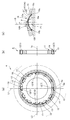
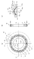
- FIG.1 (a) is a front view which shows the wave gear apparatus which concerns on this Embodiment
- FIG.1 (b) is the longitudinal cross-sectional view.
- the wave gear device 1 has a rigid internal gear 2, a cup-shaped external gear 3 coaxially disposed on the inner side, and a wave generator 4 coaxially mounted on the inner side.
- n is a positive integer
- the number of teeth of the external gear 3 is smaller than the number of teeth of the internal gear 2 by 2n.
- the external gear 3 is bent into an elliptical shape by the wave generator 4 and is engaged with the internal gear 2 at both ends in the direction of the major axis L1 of the elliptical shape.
- the meshing positions of the two gears 2 and 3 are moved by the wave generator 4 in the circumferential direction of the internal gear 2. Both gears 2 and 3 undergo relative rotation by an angle corresponding to the difference in the number of teeth while the meshing position moves by one rotation.
- FIG.2 (a) is a front view which takes out and shows the wave generator 4
- FIG.2 (b) is the longitudinal cross-sectional view
- FIG.2 (c) is the partial expanded sectional view.
- the wave generator 4 covers the outer periphery of the element holding member 11, a rigid element holding member 11 having an annular shape, a plurality of solid displacement elements 12 held on the outer peripheral portion of the element holding member 11, and , And an annular element presser 14 coaxially attached to both sides of the outer peripheral portion of the element holding member 11.
- the element holding member 11 is provided with a circular outer circumferential surface 15 having a constant width in the direction of the central axis 1a, and on the circular outer circumferential surface 15, a plurality of element holding portions 16 are arranged at constant angular intervals along the circumferential direction. It is formed.
- the element holding portion 16 is a recessed portion obtained by cutting the circular outer peripheral surface 15 to a predetermined depth with a full width, and the adjacent element holding portions 16 are partitioned by a partition portion 17 having a predetermined thickness in the circumferential direction. . In the present example, twelve element holding portions 16 are formed.
- the element holding portion 16 has a holding surface 16a orthogonal to the radial line 18 of the element holding member 11, and the holding surface 16a has a distance from the intersection point P1 with the radial line 18 to the end 16b on one side Less than the distance to the side edge 16c.
- Solid displacement elements 12 are held in each of the element holding portions 16 one by one.
- the solid displacement element 12 is formed by curving a rectangular plate element having a width substantially the same as the width of the holding surface 16 a and longer than the length of the holding surface 16 a in an arc shape.
- the solid displacement element 12 is a monomorph type deformation element including a rectangular electrode plate 21 curved in an arc shape and a plate-like piezoelectric element 22 stacked on the concave side of the electrode plate 21. It is also possible to use a shape memory alloy as the solid displacement element 12.
- the element displacement member 12 held by the element holding portion 16 is held by the element presser 14 from both sides so as not to slip out in the width direction.
- the element retainers 14 are attached to side portions on both sides of the partition 17 between the element holders 16. Further, each of the solid displacement elements 12 presses the inner peripheral surface of the flexible ring 13 disposed on the outer side in the radial direction from the inner side.
- the initial setting shape of the solid displacement element 12 is an arc shape 12A which is bridged from one end 16b of the holding surface 16a to the other end 16c as shown by a solid line in FIG.
- the convex side surface 12 a faces outward in the radial direction.
- the arc shape 12A is a flat arc shape having a lower height (height in the radial direction) from the holding surface 16a as compared to the semicircular shape 12B indicated by an imaginary line.
- One first end 12b of the solid displacement element 12 is hinged (pin coupled) to one end 16b of the holding surface 16a, and the solid displacement element 12 is fixed to the holding surface 16a about the first end 12b. It can be pivoted towards and away from.
- the other second end 12 c of the solid displacement element 12 is a free end, and is free to move in the direction toward and away from the first end 12 b.
- the vertex P is set to be located on the radial line 18 orthogonal to the holding surface 16a.
- the apex P of the convex side surface 12a is at the lowest position, and this position is set to be located on the circular outer peripheral surface 15 of the element holding member 11. It is done.
- the apex P is set to a position projecting outward in the radial direction from the circular outer circumferential surface 15 by a predetermined amount There is.
- solid displacement elements 12 positioned at both ends of the major axis L1 of the elliptical shape, that is, solid displacement elements 12 (1) in FIG.
- Solid displacement elements 12 which deform 12 (7) into a semicircular shape 12B and located at both ends of a short axis L2 orthogonal to this, ie, solid displacement elements 12 (4), 12 (10) in FIG. 2 (a)
- the deformation amount of each solid displacement element 12 gradually approaches the semicircular shape 12B. increase.
- an elliptical shape circumscribing the vertex P of each solid displacement element 12 is defined.
- a flexible ring 13 is mounted on the outer periphery of the element holding member 11.
- the inner diameter of the annular ring 13 is slightly larger than the circular outer peripheral surface 15 of the element holding member 11.
- the annulus 13 is radially deflected by the solid displacement elements 12 deformed as described above to an elliptical shape defined by their apexes P.
- the diameter line passing through the solid displacement elements 12 (1) and 12 (7) is the position of the major axis L1
- the diameter line passing through the solid displacement elements 12 (4) and 12 (10) Is the position of the minor axis L2.
- the flexible ring 13 is fitted on the inner peripheral surface of the flexible external gear 3. Therefore, the external gear 3 is also bent into an elliptical shape by the ring 13 bent into an elliptical shape. As a result, the external teeth 3a of the external gear 3 mesh with the internal teeth 2a of the internal gear 2 at both ends of the elliptical major axis L1.
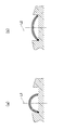
- FIG. 3 shows a deformed state of the solid displacement element 12.
- the elliptical shape rotates about the central axis 1a (see FIG. 1), and the meshing position of both gears 2 and 3 moves in the circumferential direction Do. That is, the solid displacement element 12 defining the minor axis position L2 of the elliptical shape gradually shrinks into a semicircular shape 12B, and defines the major axis position of the elliptical shape. Conversely, the solid displacement element 12 of the semicircular shape 12B defining the major axis position of the elliptical shape gradually extends back to the flat arc shape 12A, and defines the minor axis position of the elliptical shape.
- the wave generator 4 of this example can handle a large load torque by utilizing the change in rigidity, the amount of deformation and the deformation force accompanying the deformation of the solid displacement element 12 having the arc shape as described above. This point will be described below.
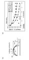
- FIG. 4 (a) is an explanatory view showing the displacement amount of the arc shape of the solid displacement element 12 in the chord direction and the radial direction
- FIG. 4 (b) shows the relationship between the flat ratio of the solid displacement element 12 and the displacement ratio. It is a graph.
- the amount of displacement of the arc-shaped solid displacement element 12 increases as it approaches the semicircular shape in both ⁇ x (in the chord direction of the arc) and ⁇ y (in the radial direction of the arc). That is, assuming that the arc radius of the arc shape is R, the radius of the semicircular shape is Ro, and the flatness of the arc shape is R / Ro, the flatness becomes larger as it approaches 1. Also, as the flatness ratio decreases from around 2, the displacement amount ratio increases. Furthermore, up to the vicinity of the semicircular shape, there is a relationship of ⁇ y> ⁇ x. It can be seen that the horizontal displacement of the apex P of the convex side, which is the maximum position of the displacement amount ⁇ y, becomes smaller as it approaches the semicircular shape.
- the solid displacement element 12 disposed at a position corresponding to the meshing position of the external gear and the internal gear is deformed into a semicircular shape. Therefore, at the meshing position, the apex P of the convex side surface of the solid displacement element 12 is largely displaced outward in the radial direction, so it is easy to secure a displacement amount necessary for bending the external gear.
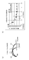
- FIG. 5 (a) is an explanatory view showing the radial rigidity of the solid displacement element 12
- FIG. 5 (b) is a graph showing the relationship between the flatness of the solid displacement element 12 and the radial rigidity.
- the radial rigidity of the solid displacement element 12 increases as the flatness ratio increases from 2 to 1 and approaches a semicircular shape (when the flatness ratio approaches 1) ) Become bigger rapidly.
- the solid displacement element 12 is deformed into a semicircular shape at the position of the major axis L1 of the elliptical shape which is the meshing position of both the gears 2 and 3, so the solid displacement element 12 in the meshing position receives a large load torque. Can receive.
- FIG. 6 (a) is an explanatory view showing the amount of contraction in the chord direction and the amount of contraction in the arc direction of the solid displacement element 12
- FIG. 6 (b) is a graph showing the relationship between the aspect ratio and the contraction rate.
- the amount of contraction for deforming the solid displacement element 12 into a semicircular shape is the amount of contraction in the arc direction (arrow B) compared to the amount of contraction in the chord direction (direction along arrow A).
- Direction is very small.
- the amount of contraction in the arc direction may be slightly increased even when approaching a semicircular shape.
- the solid displacement element 12 Based on the deformation and rigidity of the circular arc shape of the solid displacement element 12, the solid displacement element 12 is deformed into a semicircular shape at the major axis position of the elliptical shape which is the meshing position of both gears 2, 3, It is desirable to return to a flat arc shape. Further, it is desirable to use a monomorph type deformation element in which the arc radius R of the arc shape and the radius Ro of the semicircular shape satisfy the following conditional expression. 1 ⁇ R / Ro ⁇ 2
- a plurality of arc-shaped solid displacement elements 12 are provided at equal angular intervals in the circumferential direction inside the flexible ring 13 in contact with the inner periphery of the external gear 3 It is arranged.
- each solid displacement element 12 By repeatedly deforming each solid displacement element 12 between a circular arc shape and a semicircular shape in a constant cycle, each portion in the circumferential direction of the external gear 3 can be repeatedly bent in the radial direction, and the meshing position Can be moved in the circumferential direction.
- the solid displacement element 12 is deformed into a semicircular shape in the vicinity of the major axis L1 of the elliptical shape where the radial load by the meshing of both the gears 2 and 3 of the wave gear device 1 becomes maximum.
- the strength of rigidity in the radial direction, displacement amount and deformation force when each solid displacement element 12 is deformed into a semicircular shape is used, so that the wave generator 4 capable of receiving a large load torque can be realized. .
- the flexible ring 13 is disposed between the external gear 3 and the solid displacement element 12, and the top surface portion of the convex side surface of the solid displacement element 12 is the inner circumferential surface of the ring 13.
- the pressure is applied to bend the ring 13 into an elliptical shape, and the external gear 3 is bent into an oval through the ring 13.
- the ring 13 may be omitted, and the top surface portion of the convex side of the solid displacement element 12 may be brought into contact with the inner peripheral surface of the external gear 3, and the external gear 3 may be bent directly by the solid displacement element 12. It is possible.
- the external gear 3 is bent in an elliptical shape, but it is also possible to bend the external gear 3 into a shape that engages with the internal gear 2 simultaneously at three locations.
- twelve solid displacement elements 12 are disposed, but other numbers of solid displacement elements may be disposed. At least four or more solid displacement elements 12 may be arranged at equal angular intervals.
- connection-type solid displacement element of the structure shown in FIG. 8 is a solid displacement element.
- the coupled solid displacement element 30 is a coupling end in which the first and second solid displacement elements 31, 32 are hinged (pin coupled) to each other at both ends in their longitudinal direction. It has a flat cylindrical shape with 33, 34.
- the first and second solid displacement elements 31 and 32 are the same as the solid displacement element 12 described above.
- connection end 33 is movable only in the radial direction, and the other connection end 34 is movable in the direction toward and away from the connection end 33.
- connection-type solid displacement elements 30 when the connection-type solid displacement elements 30 are energized, the first and second solid displacement elements 31 and 32 deform from a flat arc shape to a semicircular shape. As a result, the coupled solid displacement element 30 is deformed into a cylindrical shape as shown in FIG. 8 (a).
- the displacement amount of the apex P for pressing the external gear 3 is a single solid displacement element It can be doubled compared to.
- FIG.9 (a) is a front view which shows another example of the wave generator 4
- FIG.9 (b) is the longitudinal cross-sectional view
- FIG.9 (c) is the partial expanded sectional view.
- the basic configuration of the wave generator 40 of this example is the same as that of the wave generator 4 described above. Therefore, the corresponding parts in the wave generator 40 are denoted by the same reference numerals, and the description thereof will be omitted.
- each element holding portion 16 is the inclined holding surface 161a.
- the inclined holding surface 161a is an inclined plane which is inclined at a predetermined angle in the circumferential direction with respect to an orthogonal surface 160 indicated by a dashed dotted line orthogonal to the radius line of the circular outer peripheral surface 15. In this example, it is an inclined plane inclined at 10 degrees with respect to the orthogonal plane 160, and is inclined inward in the radial direction with respect to the orthogonal plane 160 from one end 161b thereof to the other end 161c.
- One end 12b of the solid displacement element 12 is hinged to one end 161b of the inclined holding surface 161a, and the other end 12c is slidable along the inclined holding surface 161a.
- the solid displacement element 12 is in a semicircular shape 12 B, its apex P is set to be located on the radial line 18.
- the apex P of the convex side surface 12a is at the lowest position, and this position is set to be located on the circular outer peripheral surface 15 of the element holding member 11. It is done.
- the apex P is set to a position projecting outward in the radial direction from the circular outer circumferential surface 15 by a predetermined amount There is.
- solid displacement elements 12 positioned at both ends of the major axis L1 of the elliptical shape, ie, solid displacement elements 12 (1) in FIG.
- Solid displacement elements 12 which deform 12 (7) into a semicircular shape 12B and located at both ends of a short axis L2 orthogonal to this, ie, solid displacement elements 12 (4), 12 (10) in FIG. 2 (a) Is held in a flat arc shape 12A.
- the deformation amount of each solid displacement element 12 gradually approaches the semicircular shape 12B. increase.
- an elliptical shape is defined in which the apexes P of the solid displacement elements 12 are inscribed.
- FIG. 10 is an explanatory view showing the movement of the apex P due to the deformation of the solid displacement element 12.
- FIG. 10 (a) is an explanatory view in the case where the orthogonal plane 160 is used as a holding surface
- FIG. (B2) is an explanatory view in the case of using the inclined holding surface 162 inclining by 5 degrees with respect to the orthogonal plane 160
- (b3) ) Is an explanatory view in the case of using the inclined holding surface 163 which is inclined 15 degrees with respect to the orthogonal surface 160.
- the movement locus M0 of the vertex P due to the deformation of the solid displacement element 12 held in the orthogonal plane 160 is a linear shape inclined outward in the radial direction, and the displacement amount in the radial direction Is V0, and the displacement in the direction orthogonal to the radial line 18 is H0.
- the movement loci M1, M2, and M3 of the vertex P are curved in one direction.
- the displacement amounts V1, V2, V3 in the radial direction are substantially the same as the displacement amount V0, but the displacement amounts H1, H2, H3 in the direction orthogonal to the radial line 18 are smaller than in the case of the orthogonal surface 160.
- the position of the apex P of the initial arc-shaped solid displacement element 12A and the position of the apex P after being deformed into a semicircle have substantially the radius Draw a movement locus M1 located on the line 18. Therefore, the movement of the apex P (the contact position with the inner circumferential surface of the external gear) of each solid displacement element 12 pressing the external gear becomes close to the elliptical movement of the external gear. As a result, a displacement closer to the displacement of the external gear by the wave generator using a rigid body plug having an elliptical contour can be applied to the external gear using the solid displacement element 12.
- the inclination angle of the inclined holding surface may be set to an appropriate angle according to the size, shape, displacement amount of the solid displacement element, the outer diameter of the wave generator, and the like. As shown in FIG. 10 (b1), the position of the apex P of the initial arc-shaped solid displacement element 12 and the position of the apex P after being deformed into a semicircular shape are set so as to be located substantially on the radius line 18. Is desirable.
Landscapes
- Engineering & Computer Science (AREA)
- General Engineering & Computer Science (AREA)
- Mechanical Engineering (AREA)
- Retarders (AREA)
- General Electrical Machinery Utilizing Piezoelectricity, Electrostriction Or Magnetostriction (AREA)
Abstract
Description
1 < R/Ro < 2
図4(a)は固体変位素子12の円弧形状の弦方向および半径方向の変位量を示す説明図であり、図4(b)は固体変位素子12の偏平率と変位量割合の関係を示すグラフである。
1 < R/Ro < 2
図9(a)は波動発生器4の別の例を示す正面図であり、図9(b)はその縦断面図であり、図9(c)はその部分拡大断面図である。本例の波動発生器40の基本構成は上記の波動発生器4と同一である。よって、波動発生器40における対応する部位には同一の符号を付し、それらの説明は省略する。
Claims (10)
- 可撓性の外歯歯車の円周方向の各部を、複数個の固体変位素子を用いて、半径方向に所定の振幅および周期で撓めて、剛性の内歯歯車に対する前記外歯歯車のかみ合い位置を円周方向に移動させ、前記外歯歯車と前記内歯歯車の歯数差に応じた相対回転を両歯車の間に生じさせる波動歯車装置の波動発生器であって、
前記固体変位素子は、モノモルフ型あるいはバイモルフ型の長方形の板状素子を円弧形状に湾曲させたものであり、通電により、前記円弧形状から、当該円弧形状の円弧半径よりも小さな半径の半円形状に変形可能であり、
前記半円形状に変形した前記固体変位素子によって撓められる前記外歯歯車の部分が、前記内歯歯車にかみ合うことを特徴とする波動歯車装置の波動発生器。 - 前記固体変位素子の前記半円形状の前記半径をRo、前記円弧半径をRとすると、
1 < R/Ro < 2
である請求項1に記載の波動歯車装置の波動発生器。 - 前記固体変位素子を保持する素子保持部材を有し、
前記素子保持部材は、前記外歯歯車の内周面に対峙可能な円形外周面と、当該円形外周面において円周方向に等角度間隔に形成された複数の素子保持部とを備え、
前記素子保持部には、前記固体変位素子の凸側面が、前記円形外周面の半径方向の外方を向く状態に保持され、
前記固体変位素子における長さ方向の一方の第1端部は、移動しないように前記素子保持部にピン結合され、他方の第2端部は、前記第1端部に対して接近および離れる方向に移動が自由である、
請求項1に記載の波動歯車装置の波動発生器。 - 前記素子保持部のそれぞれは、前記円形外周面の半径線に直交する直交面に対して、前記円周方向に沿った方向に傾斜する保持面を備え、
前記固体変位素子の前記第1端部は前記保持面における前記円周方向の一方の端にヒンジ結合され、前記第2端部は前記保持面に沿ってスライド自在である請求項3に記載の波動歯車装置の波動発生器。 - 前記固体変位素子の前記凸側面の頂面部分は、直接、あるいは、可撓性の円環を介して、前記外歯歯車の内周面を押圧する請求項1に記載の波動歯車装置の波動発生器。
- 可撓性の外歯歯車の円周方向の各部を、複数個の固体変位素子を用いて、半径方向に所定の振幅および周期で撓めて、剛性の内歯歯車に対する前記外歯歯車のかみ合い位置を円周方向に移動させ、前記外歯歯車と前記内歯歯車の歯数差に応じた相対回転を両歯車の間に生じさせる波動歯車装置の波動発生器であって、
前記固体変位素子は第1、第2固体変位素子から形成され、
前記第1、第2固体変位素子のそれぞれは、モノモルフ型あるいはバイモルフ型の長方形の板状素子を円弧形状に湾曲させたものであり、通電により、前記円弧形状から、当該円弧形状の円弧半径よりも小さな半径の半円形状に変形可能であり、
前記固体変位素子は、前記第1、第2固体変位素子がそれらの長さ方向の両端において相互に連結された筒形状をしており、前記第1、第2固体変位素子が前記半円形状に変形することにより、前記筒形状から円筒形状に変形し、
前記円筒形状に変形した前記固体変位素子によって撓められる前記外歯歯車の部分が、前記内歯歯車にかみ合うことを特徴とする波動歯車装置の波動発生器。 - 前記固体変位素子の前記半円形状の前記半径をRo、前記円弧半径をRとすると、
1 < R/Ro < 2
である請求項6に記載の波動歯車装置の波動発生器。 - 前記固体変位素子を保持する素子保持部材を有し、
前記素子保持部材は、前記外歯歯車の内周面に対峙可能な円形外周面と、当該円形外周面において円周方向に等角度間隔に形成された複数の素子保持部とを備え、
前記固体変位素子は、前記第1、第2固体変位素子の凸側面が、前記円形外周面の半径方向を向き、当該半径方向への変形が可能な状態で、前記素子保持部に保持されている、
請求項6に記載の波動歯車装置の波動発生器。 - 前記固体変位素子の前記半径方向の外方を向く前記凸側面の頂面部分は、直接、あるいは、可撓性の円環を介して、前記外歯歯車の内周面を押圧する請求項6に記載の波動歯車装置の波動発生器。
- 請求項1ないし9のうちのいずれか一つの項に記載の波動発生器を有していることを特徴とする波動歯車装置。
Priority Applications (7)
| Application Number | Priority Date | Filing Date | Title |
|---|---|---|---|
| JP2016574613A JP6338704B2 (ja) | 2015-02-13 | 2015-02-13 | 波動歯車装置および波動発生器 |
| CN201580073991.9A CN107210686B (zh) | 2015-02-13 | 2015-02-13 | 波动齿轮装置及波动发生器 |
| PCT/JP2015/054040 WO2016129123A1 (ja) | 2015-02-13 | 2015-02-13 | 波動歯車装置および波動発生器 |
| US15/550,697 US10393250B2 (en) | 2015-02-13 | 2015-02-13 | Strain wave gearing and wave generator |
| KR1020177024300A KR101967183B1 (ko) | 2015-02-13 | 2015-02-13 | 파동기어장치 및 파동발생기 |
| EP15881997.9A EP3258590B1 (en) | 2015-02-13 | 2015-02-13 | Strain wave gearing and wave generator |
| TW105102040A TWI665396B (zh) | 2015-02-13 | 2016-01-22 | 諧波齒輪裝置及諧波產生器 |
Applications Claiming Priority (1)
| Application Number | Priority Date | Filing Date | Title |
|---|---|---|---|
| PCT/JP2015/054040 WO2016129123A1 (ja) | 2015-02-13 | 2015-02-13 | 波動歯車装置および波動発生器 |
Publications (1)
| Publication Number | Publication Date |
|---|---|
| WO2016129123A1 true WO2016129123A1 (ja) | 2016-08-18 |
Family
ID=56614288
Family Applications (1)
| Application Number | Title | Priority Date | Filing Date |
|---|---|---|---|
| PCT/JP2015/054040 Ceased WO2016129123A1 (ja) | 2015-02-13 | 2015-02-13 | 波動歯車装置および波動発生器 |
Country Status (7)
| Country | Link |
|---|---|
| US (1) | US10393250B2 (ja) |
| EP (1) | EP3258590B1 (ja) |
| JP (1) | JP6338704B2 (ja) |
| KR (1) | KR101967183B1 (ja) |
| CN (1) | CN107210686B (ja) |
| TW (1) | TWI665396B (ja) |
| WO (1) | WO2016129123A1 (ja) |
Cited By (1)
| Publication number | Priority date | Publication date | Assignee | Title |
|---|---|---|---|---|
| WO2020234945A1 (ja) * | 2019-05-17 | 2020-11-26 | 株式会社ハーモニック・ドライブ・システムズ | コロ軸受式波動発生器を備えた波動歯車装置 |
Families Citing this family (7)
| Publication number | Priority date | Publication date | Assignee | Title |
|---|---|---|---|---|
| US11202704B2 (en) | 2011-10-19 | 2021-12-21 | Twelve, Inc. | Prosthetic heart valve devices, prosthetic mitral valves and associated systems and methods |
| JP6552745B2 (ja) * | 2016-07-30 | 2019-07-31 | 株式会社ハーモニック・ドライブ・システムズ | 波動発生器および波動歯車装置 |
| CN108397536B (zh) * | 2018-05-04 | 2023-07-25 | 顺德职业技术学院 | 新型波发生器的谐波传动机构 |
| JP7535486B2 (ja) * | 2021-10-25 | 2024-08-16 | 美的集団股▲フン▼有限公司 | 波動歯車装置、波動歯車装置の製造方法、ロボット用関節装置及び歯車部品 |
| CN117823595B (zh) * | 2024-01-29 | 2024-09-24 | 重庆大学 | 一种多层复合柔轮型谐波减速器及柔性工业机器人 |
| CN118149069B (zh) * | 2024-01-29 | 2024-11-15 | 重庆大学 | 一种二维多头波发生器型谐波减速器及自适应工业机器人 |
| CN117869555B (zh) * | 2024-01-29 | 2024-09-06 | 重庆大学 | 一种三维多头波发生器型谐波减速器及单关节多自由度工业机器人 |
Citations (5)
| Publication number | Priority date | Publication date | Assignee | Title |
|---|---|---|---|---|
| JPS63110966A (ja) * | 1986-10-27 | 1988-05-16 | Nok Corp | 表面波動モ−タ |
| JPH01158250A (ja) * | 1987-12-15 | 1989-06-21 | Haamonitsuku Drive Syst:Kk | 撓み噛み合い式歯車装置 |
| JPH0524750B2 (ja) * | 1985-12-17 | 1993-04-08 | Daikin Ind Ltd | |
| JPH07110140B2 (ja) * | 1987-01-23 | 1995-11-22 | キヤノン株式会社 | 圧電素子モータ |
| JP2000166264A (ja) * | 1998-11-30 | 2000-06-16 | Seiko Instruments Inc | 圧電アクチュエータおよびその製造方法 |
Family Cites Families (16)
| Publication number | Priority date | Publication date | Assignee | Title |
|---|---|---|---|---|
| JPS60143244A (ja) * | 1983-12-29 | 1985-07-29 | Mitsubishi Electric Corp | ハ−モニツクギヤ装置 |
| CN2525728Y (zh) * | 2002-03-04 | 2002-12-11 | 辛洪兵 | 压电谐波电机 |
| WO2005100818A1 (ja) * | 2004-04-15 | 2005-10-27 | Harmonic Drive Systems Inc. | 波動歯車装置 |
| JP4744989B2 (ja) | 2005-09-05 | 2011-08-10 | 株式会社ハーモニック・ドライブ・システムズ | 波動歯車装置および摩擦係合式波動装置 |
| JP4902227B2 (ja) * | 2006-03-01 | 2012-03-21 | 本田技研工業株式会社 | 波動歯車装置 |
| KR100988215B1 (ko) * | 2008-06-24 | 2010-10-18 | 한국과학기술연구원 | 전위기어를 이용하는 하모닉 감속기 |
| JP2011152026A (ja) | 2009-12-24 | 2011-08-04 | Aisin Seiki Co Ltd | 回転駆動装置 |
| EP2360358A1 (en) * | 2010-02-24 | 2011-08-24 | Delphi Technologies, Inc. | Electrical camshaft phaser with energy recovery |
| US9425712B2 (en) * | 2011-09-16 | 2016-08-23 | Harmonic Drive Systems Inc. | Vibration power-generating strain wave gearing |
| WO2013175533A1 (ja) * | 2012-05-23 | 2013-11-28 | 株式会社ハーモニック・ドライブ・システムズ | 波動歯車装置の波動発生器 |
| WO2013175532A1 (ja) * | 2012-05-23 | 2013-11-28 | 株式会社ハーモニック・ドライブ・システムズ | 波動歯車装置の波動発生器 |
| TWI487858B (zh) * | 2012-12-27 | 2015-06-11 | Ind Tech Res Inst | 諧波傳動裝置 |
| US9140350B2 (en) * | 2013-01-09 | 2015-09-22 | Harmonic Drive Systems Inc. | Wave gear device |
| JP5885848B2 (ja) * | 2013-05-08 | 2016-03-16 | 株式会社ハーモニック・ドライブ・システムズ | 可撓性外歯歯車の製造方法、波動歯車装置の製造方法および可撓性外歯歯車の締結方法 |
| KR20140142236A (ko) * | 2013-05-08 | 2014-12-11 | 가부시키가이샤 하모닉 드라이브 시스템즈 | 체결용 마찰판, 및 파동 기어 장치와 출력 부재의 체결고정 구조 |
| CN104218846B (zh) * | 2014-09-23 | 2016-09-07 | 江苏釜鼎能源科技有限公司 | 一种步进式压电驱动器及其驱动实现方法 |
-
2015
- 2015-02-13 CN CN201580073991.9A patent/CN107210686B/zh active Active
- 2015-02-13 WO PCT/JP2015/054040 patent/WO2016129123A1/ja not_active Ceased
- 2015-02-13 JP JP2016574613A patent/JP6338704B2/ja active Active
- 2015-02-13 EP EP15881997.9A patent/EP3258590B1/en active Active
- 2015-02-13 US US15/550,697 patent/US10393250B2/en active Active
- 2015-02-13 KR KR1020177024300A patent/KR101967183B1/ko active Active
-
2016
- 2016-01-22 TW TW105102040A patent/TWI665396B/zh active
Patent Citations (5)
| Publication number | Priority date | Publication date | Assignee | Title |
|---|---|---|---|---|
| JPH0524750B2 (ja) * | 1985-12-17 | 1993-04-08 | Daikin Ind Ltd | |
| JPS63110966A (ja) * | 1986-10-27 | 1988-05-16 | Nok Corp | 表面波動モ−タ |
| JPH07110140B2 (ja) * | 1987-01-23 | 1995-11-22 | キヤノン株式会社 | 圧電素子モータ |
| JPH01158250A (ja) * | 1987-12-15 | 1989-06-21 | Haamonitsuku Drive Syst:Kk | 撓み噛み合い式歯車装置 |
| JP2000166264A (ja) * | 1998-11-30 | 2000-06-16 | Seiko Instruments Inc | 圧電アクチュエータおよびその製造方法 |
Cited By (4)
| Publication number | Priority date | Publication date | Assignee | Title |
|---|---|---|---|---|
| WO2020234945A1 (ja) * | 2019-05-17 | 2020-11-26 | 株式会社ハーモニック・ドライブ・システムズ | コロ軸受式波動発生器を備えた波動歯車装置 |
| JPWO2020234945A1 (ja) * | 2019-05-17 | 2021-06-10 | 株式会社ハーモニック・ドライブ・システムズ | コロ軸受式波動発生器を備えた波動歯車装置 |
| TWI821536B (zh) * | 2019-05-17 | 2023-11-11 | 日商和諧驅動系統股份有限公司 | 具備滾柱軸承式諧波產生器的諧波齒輪裝置 |
| US11982343B2 (en) | 2019-05-17 | 2024-05-14 | Harmonic Drive Systems Inc. | Strain wave gearing having roller-bearing-type wave generator |
Also Published As
| Publication number | Publication date |
|---|---|
| TWI665396B (zh) | 2019-07-11 |
| KR20170109645A (ko) | 2017-09-29 |
| TW201702498A (zh) | 2017-01-16 |
| EP3258590B1 (en) | 2020-07-29 |
| EP3258590A4 (en) | 2018-11-14 |
| JPWO2016129123A1 (ja) | 2017-12-14 |
| JP6338704B2 (ja) | 2018-06-06 |
| EP3258590A1 (en) | 2017-12-20 |
| US10393250B2 (en) | 2019-08-27 |
| CN107210686A (zh) | 2017-09-26 |
| KR101967183B1 (ko) | 2019-04-09 |
| CN107210686B (zh) | 2019-02-19 |
| US20180031103A1 (en) | 2018-02-01 |
Similar Documents
| Publication | Publication Date | Title |
|---|---|---|
| WO2016129123A1 (ja) | 波動歯車装置および波動発生器 | |
| CN103356287B (zh) | 可变柔性管及具有该可变柔性管的操纵器 | |
| CN107166010B (zh) | 波动齿轮装置 | |
| JP5938933B2 (ja) | 波動歯車装置 | |
| US9118263B2 (en) | Piezo motor | |
| CN108496026B (zh) | 波动齿轮装置以及致动器 | |
| JP5633696B2 (ja) | 伸縮アクチュエータ | |
| JP2006288060A (ja) | 振動波駆動装置及び該振動波駆動装置を備える機器 | |
| EP2750281A1 (en) | Piezoelectric power generation element | |
| CN102739102A (zh) | 环形振动波致动器 | |
| JP4744989B2 (ja) | 波動歯車装置および摩擦係合式波動装置 | |
| JP5108974B2 (ja) | 摩擦型遊星動力伝達装置 | |
| US8299683B2 (en) | Ultrasonic motor | |
| JP2017137882A (ja) | ロボット及び変速機 | |
| EP3839295B1 (en) | Sliding contact-type wave generator and strain wave gearing device | |
| JP6289975B2 (ja) | 変位拡大ピエゾアクチュエータ | |
| JP6471400B2 (ja) | 発電装置 | |
| JP2013078230A5 (ja) | ||
| TWI362174B (en) | A piezoelectric motor | |
| US11879497B2 (en) | Morphable sheet structure | |
| JP6427446B2 (ja) | アクチュエータ | |
| JP2014011883A (ja) | モータ装置及びロボット装置 | |
| JP2019019862A (ja) | 波動歯車装置 | |
| ITMI20081542A1 (it) | Motore rotativo movimentato da attuatori piezoelettrici | |
| JP2007252100A (ja) | モータ装置およびレンズ駆動装置 |
Legal Events
| Date | Code | Title | Description |
|---|---|---|---|
| 121 | Ep: the epo has been informed by wipo that ep was designated in this application |
Ref document number: 15881997 Country of ref document: EP Kind code of ref document: A1 |
|
| ENP | Entry into the national phase |
Ref document number: 2016574613 Country of ref document: JP Kind code of ref document: A |
|
| NENP | Non-entry into the national phase |
Ref country code: DE |
|
| ENP | Entry into the national phase |
Ref document number: 20177024300 Country of ref document: KR Kind code of ref document: A |
|
| REEP | Request for entry into the european phase |
Ref document number: 2015881997 Country of ref document: EP |