WO2016129301A1 - 車両用進入可否判定装置 - Google Patents
車両用進入可否判定装置 Download PDFInfo
- Publication number
- WO2016129301A1 WO2016129301A1 PCT/JP2016/050236 JP2016050236W WO2016129301A1 WO 2016129301 A1 WO2016129301 A1 WO 2016129301A1 JP 2016050236 W JP2016050236 W JP 2016050236W WO 2016129301 A1 WO2016129301 A1 WO 2016129301A1
- Authority
- WO
- WIPO (PCT)
- Prior art keywords
- vehicle
- dimensional object
- road surface
- unit
- image
- Prior art date
- Legal status (The legal status is an assumption and is not a legal conclusion. Google has not performed a legal analysis and makes no representation as to the accuracy of the status listed.)
- Ceased
Links
Images


Classifications
-
- G—PHYSICS
- G06—COMPUTING OR CALCULATING; COUNTING
- G06V—IMAGE OR VIDEO RECOGNITION OR UNDERSTANDING
- G06V20/00—Scenes; Scene-specific elements
- G06V20/50—Context or environment of the image
- G06V20/56—Context or environment of the image exterior to a vehicle by using sensors mounted on the vehicle
- G06V20/58—Recognition of moving objects or obstacles, e.g. vehicles or pedestrians; Recognition of traffic objects, e.g. traffic signs, traffic lights or roads
-
- B—PERFORMING OPERATIONS; TRANSPORTING
- B60—VEHICLES IN GENERAL
- B60R—VEHICLES, VEHICLE FITTINGS, OR VEHICLE PARTS, NOT OTHERWISE PROVIDED FOR
- B60R21/00—Arrangements or fittings on vehicles for protecting or preventing injuries to occupants or pedestrians in case of accidents or other traffic risks
-
- G—PHYSICS
- G06—COMPUTING OR CALCULATING; COUNTING
- G06T—IMAGE DATA PROCESSING OR GENERATION, IN GENERAL
- G06T1/00—General purpose image data processing
-
- G—PHYSICS
- G06—COMPUTING OR CALCULATING; COUNTING
- G06T—IMAGE DATA PROCESSING OR GENERATION, IN GENERAL
- G06T7/00—Image analysis
- G06T7/10—Segmentation; Edge detection
- G06T7/13—Edge detection
-
- G—PHYSICS
- G06—COMPUTING OR CALCULATING; COUNTING
- G06T—IMAGE DATA PROCESSING OR GENERATION, IN GENERAL
- G06T7/00—Image analysis
- G06T7/10—Segmentation; Edge detection
- G06T7/174—Segmentation; Edge detection involving the use of two or more images
-
- G—PHYSICS
- G06—COMPUTING OR CALCULATING; COUNTING
- G06T—IMAGE DATA PROCESSING OR GENERATION, IN GENERAL
- G06T7/00—Image analysis
- G06T7/60—Analysis of geometric attributes
-
- G—PHYSICS
- G06—COMPUTING OR CALCULATING; COUNTING
- G06V—IMAGE OR VIDEO RECOGNITION OR UNDERSTANDING
- G06V20/00—Scenes; Scene-specific elements
- G06V20/50—Context or environment of the image
- G06V20/56—Context or environment of the image exterior to a vehicle by using sensors mounted on the vehicle
- G06V20/58—Recognition of moving objects or obstacles, e.g. vehicles or pedestrians; Recognition of traffic objects, e.g. traffic signs, traffic lights or roads
- G06V20/586—Recognition of moving objects or obstacles, e.g. vehicles or pedestrians; Recognition of traffic objects, e.g. traffic signs, traffic lights or roads of parking space
-
- G—PHYSICS
- G08—SIGNALLING
- G08G—TRAFFIC CONTROL SYSTEMS
- G08G1/00—Traffic control systems for road vehicles
- G08G1/16—Anti-collision systems
-
- H—ELECTRICITY
- H04—ELECTRIC COMMUNICATION TECHNIQUE
- H04N—PICTORIAL COMMUNICATION, e.g. TELEVISION
- H04N7/00—Television systems
- H04N7/18—Closed-circuit television [CCTV] systems, i.e. systems in which the video signal is not broadcast
-
- B—PERFORMING OPERATIONS; TRANSPORTING
- B60—VEHICLES IN GENERAL
- B60R—VEHICLES, VEHICLE FITTINGS, OR VEHICLE PARTS, NOT OTHERWISE PROVIDED FOR
- B60R2300/00—Details of viewing arrangements using cameras and displays, specially adapted for use in a vehicle
- B60R2300/30—Details of viewing arrangements using cameras and displays, specially adapted for use in a vehicle characterised by the type of image processing
- B60R2300/304—Details of viewing arrangements using cameras and displays, specially adapted for use in a vehicle characterised by the type of image processing using merged images, e.g. merging camera image with stored images
-
- B—PERFORMING OPERATIONS; TRANSPORTING
- B60—VEHICLES IN GENERAL
- B60R—VEHICLES, VEHICLE FITTINGS, OR VEHICLE PARTS, NOT OTHERWISE PROVIDED FOR
- B60R2300/00—Details of viewing arrangements using cameras and displays, specially adapted for use in a vehicle
- B60R2300/80—Details of viewing arrangements using cameras and displays, specially adapted for use in a vehicle characterised by the intended use of the viewing arrangement
-
- G—PHYSICS
- G06—COMPUTING OR CALCULATING; COUNTING
- G06T—IMAGE DATA PROCESSING OR GENERATION, IN GENERAL
- G06T2207/00—Indexing scheme for image analysis or image enhancement
- G06T2207/20—Special algorithmic details
- G06T2207/20212—Image combination
- G06T2207/20224—Image subtraction
-
- G—PHYSICS
- G06—COMPUTING OR CALCULATING; COUNTING
- G06T—IMAGE DATA PROCESSING OR GENERATION, IN GENERAL
- G06T2207/00—Indexing scheme for image analysis or image enhancement
- G06T2207/30—Subject of image; Context of image processing
- G06T2207/30248—Vehicle exterior or interior
- G06T2207/30252—Vehicle exterior; Vicinity of vehicle
-
- G—PHYSICS
- G06—COMPUTING OR CALCULATING; COUNTING
- G06V—IMAGE OR VIDEO RECOGNITION OR UNDERSTANDING
- G06V2201/00—Indexing scheme relating to image or video recognition or understanding
- G06V2201/12—Acquisition of 3D measurements of objects
Definitions
- the present invention is premised on a device for processing an image around the vehicle taken by a camera attached to the vehicle, and in particular, an image around the vehicle is converted into a bird's-eye view image and processed.
- Patent Document 1 An apparatus that corrects and displays distortion of a three-dimensional object generated by overhead conversion on an image obtained by overhead conversion has been proposed (for example, Patent Document 1).
- the vehicle peripheral image display device described in Patent Document 1 can correct the distortion of the external shape of the three-dimensional object existing on the road surface, but if a part of the three-dimensional object is not grounded on the road surface, The part of an object that floats in the air is transformed into a bird's-eye view image and is projected so as to fall on the road surface in a direction away from the vehicle.
- the three-dimensional object is a place where the vehicle should originally enter like a garage, there is a problem that it is not possible to determine whether or not the vehicle can enter only by looking at the overhead view image.
- the present invention has been made in view of the above-described problems, and determines whether or not a vehicle can enter a solid object detected on a road surface around the vehicle by determining whether or not there is a space in which the vehicle can enter. Is determined.
- a vehicular entry propriety determination device includes an imaging unit that is attached to a vehicle and that captures a range including a road surface around the vehicle, and an original image captured by the imaging unit.
- An image conversion unit that converts an image into a virtual image viewed from a predetermined viewpoint position, a three-dimensional object detection unit that detects a three-dimensional object having a height from a road surface, and the inside of the three-dimensional object or
- a vehicle entry availability determination unit that determines whether the vehicle is allowed to enter a gap between different three-dimensional objects.
- a three-dimensional object having a part floating in the air around the vehicle and an overhang portion can be obtained. It is possible to determine whether or not a vehicle can contact a three-dimensional object having a floating region that is not in contact with the ground, such as a three-dimensional object. Therefore, since it is possible to show the driver whether the vehicle can enter the solid object and the position where the vehicle can approach, it is possible to prevent the vehicle from contacting the solid object.
- FIG. 3 is a functional block diagram illustrating a detailed functional configuration of a three-dimensional object detection unit in the vehicular approachability determination device according to the first embodiment.
- 1 is a hardware block diagram illustrating a hardware configuration of a vehicle entry permission / prohibition determining device according to a first embodiment.
- 3 is a flowchart illustrating a flow of a series of processes performed in the first embodiment. It is a figure which shows an example of the original image imaged with the front camera.
- FIG. 7 is a diagram illustrating an example in which a frame difference (first frame difference) is subtracted from a virtual image at time t ⁇ t from a virtual image at time t.
- FIG. 9B It is a figure which shows a mode that the window for evaluating a light and shade distribution was set on the original image in order to specify a solid object area
- the present invention detects a three-dimensional object around the vehicle, determines whether or not the vehicle can enter the detected three-dimensional object, and transmits the result to the driver.
- the present invention is applied as a vehicle entry propriety determination device.
- the vehicular approachability determination apparatus 100 is mounted on a vehicle 10 and captures an image including a road surface in front of the vehicle 10, and an output from the imaging unit 12.
- An image input unit 20 that converts the processed image signal into an original image 70 in a digital image format that can be handled by a computer, an image conversion unit 30 that converts the original image 70 into a virtual image 72 viewed from a predetermined viewpoint position, and a virtual image From the image 72, the three-dimensional object detection unit 40 that detects a three-dimensional object having a height from the road surface, and whether or not the vehicle 10 can enter the inside of the detected three-dimensional object or the gap between the detected three-dimensional objects is determined.
- a vehicle entry availability determination unit 50, and a vehicle entry availability range display unit 60 that displays a range determined to be entry impossible or entry possible as a result of vehicle entry availability determination by the vehicle entry availability determination unit 50. .
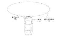
- the imaging unit 12 is attached to the front of the vehicle 10 as shown in FIG. 2 and images the inside of the front observation range 14 including the road surface closest to the vehicle 10 over a visual field range of about 180 °.
- the three-dimensional object detection unit 40 is imaged by the imaging unit 12 (FIG. 1) at a predetermined time interval and converted by the image conversion unit 30 (FIG. 1).
- a predicted virtual image 72 ′ (t) at time t is generated from the arithmetic unit 40a and a virtual image 72 (t ⁇ t) generated from the original image 70 (t ⁇ t) obtained at time (t ⁇ t).
- the second frame difference calculation unit 40b that performs a frame difference by subtracting the predicted virtual image 72 ′ (t) from the virtual image 72 (t) actually obtained at time t.
- a pixel whose brightness changes greatly between adjacent pixels i.e., an It is considered that the three-dimensional object is configured based on the detection result of the edge detection unit 40c for detecting pixels constituting the wedge, the calculation result of the first frame difference calculation unit 40a and the second frame difference calculation unit 40b, and the detection result of the edge detection unit 40c.
- a three-dimensional object region clustering unit 40d for detecting a region to be generated.
- the vehicle entry propriety determination unit 50 includes a three-dimensional object region extraction unit 50 a that extracts a region corresponding to a three-dimensional object detected by the three-dimensional object detection unit 40 from the original image 70.
- a road surface projection position calculation unit 50b that calculates a road surface projection position indicating a limit position where the vehicle can approach the solid object is extracted from the solid object region extracted by the three-dimensional object region extraction unit 50a.
- a vehicle accessible space identifying unit 50c for identifying whether or not there is a space in which the vehicle 10 can enter in the space between the three-dimensional objects.
- a vehicle entry permission / prohibition determination device 100 is mounted on a vehicle 10 and performs an required image processing and arithmetic processing, an ECU (electronic control unit) 110, and an imaging unit 12 (see FIG. 1), a vehicle state sensor 140 composed of a steering angle sensor and a distance sensor for calculating the amount and direction of movement of the vehicle 10 by detecting the behavior of the vehicle 10, and a vehicle approach
- the monitor 150 which displays the processing result of the availability range display part 60 (FIG. 1) is comprised.
- the ECU 110 further includes a CPU 112 that transmits / receives necessary data and executes programs, a camera interface 114 that is connected to the CPU 112 and controls the front camera 12a, and a sensor interface 116 that acquires measurement results of the vehicle state sensor 140. And an image processing module 118 that executes image processing using a predetermined program built therein, a memory 120 that stores intermediate results of image processing, necessary constants, programs, and the like, and display control that controls the monitor 150 Part 122.
- This software is stored in the above-described memory 120, and is appropriately executed as necessary. Note that the software may be stored in the CPU 112 or the image processing module 118 as necessary.
- Step S10 Image conversion processing is performed. Specifically, the captured original image is converted into a virtual image.
- Step S20 A three-dimensional object detection process is performed. Specific processing contents will be described later.
- Step S30 Three-dimensional object region extraction processing is performed. Specific processing contents will be described later.
- Step S40 A vehicle entry permission determination process is performed. Specific processing contents will be described later.
- Step S50 A vehicle inaccessible range display process is performed. Specific processing contents will be described later.
- FIG. 1 (Description of image conversion process) First, the effect
- the image conversion process is performed in the imaging unit 12, the image input unit 20, and the image conversion unit 30 described in FIG.
- the output of the front camera 12a (FIG. 4) constituting the imaging unit 12 is converted into a digital image by the image input unit 20, and input to the image conversion unit 30 as an original image 70 shown in FIG. 6A.
- the original image captured at time t is denoted as 70 (t).
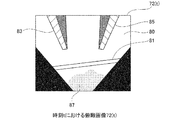
- FIG. 6A is an image of the road surface 80 in front of the vehicle 10 (FIG. 1).
- a lane marker 81 is drawn on the road surface, and a garage 82 (three-dimensional object) for parking the vehicle 10 is installed in the back of the lane marker.
- the garage 82 has legs 83 and 85 on the left and right, respectively.
- a car shadow 87 that is a shadow of the vehicle 10 is shown below the original image 70 (t).
- the image conversion unit 30 converts the original image 70 (t) shown in FIG. 6A into a virtual image 72 (t) (overhead image) obtained by looking down the vehicle 10 from directly above, as shown in FIG. 6B. Convert. Although a specific description of the conversion method is omitted, the original image 70 (t) is converted to the vehicle 10 using the installation layout information (camera height, camera depression angle, lens parameters) of the front camera 12a (FIG. 4).
- a virtual image 72 (t) is obtained by performing coordinate transformation for projecting onto a road surface on which is present. Note that a virtual image obtained by converting the original image 70 (t) is denoted as 72 (t).
- the left and right leg portions 83 and 85 of the garage 82 (three-dimensional object) shown in the original image 70 (t) captured by the front camera 12 a are the virtual image 72.
- the image is deformed so as to fall on the road surface in an upward direction, that is, in a direction away from the vehicle 10. And it deform
- the deformation of the legs 83 and 85 that is, the deformation of the region having a height from the road surface, is radial from the installation position P1 (FIG. 6B) of the front camera 12a (FIG. 4) toward the periphery of the virtual image 72 (t). Occurs to spread.
- invisible areas 86 and 86 that are out of the field of view of the front camera 12a are generated.
- a predetermined gray value for example, 0
- FIG. 3 (Overview of the three-dimensional object detection process) Next, the operation of the three-dimensional object detection process will be described using FIG. 3 and FIGS. 7A to 7E.
- the three-dimensional object detection process is performed in the three-dimensional object detection unit 40 of FIG.
- the three-dimensional object detection unit 40 detects a three-dimensional object from virtual images generated from two original images captured at a time interval ⁇ t.
- a virtual image 72 (t) generated from the original image 70 (t) imaged at time t and a virtual image 72 generated from the original image 70 (t- ⁇ t) imaged at time t ⁇ t.
- the description will be made assuming that a three-dimensional object is detected from (t ⁇ t).
- the frame difference between the two virtual images 72 (t) and 72 (t ⁇ t) is calculated. This process is performed by the first frame difference calculation unit 40a in FIG.
- a virtual image 72 (t) at time t is predicted from the virtual image 72 (t ⁇ t) to generate a predicted virtual image 72 ′ (t), and this predicted virtual image 72 ′.
- a frame difference between (t) and the virtual image 72 (t) actually obtained at time t is calculated. This process is performed by the second frame difference calculation unit 40b in FIG.
- the predicted virtual image 72 ′ (t) is specifically generated as follows. That is, the moving amount and moving direction of the vehicle 10 during the time interval ⁇ t are measured at any time by the vehicle state sensor 140 (FIG. 4). Then, the virtual image 72 (t ⁇ t) is translated and rotated so as to correspond to the movement amount and the movement direction of the vehicle 10 during the measured time interval ⁇ t, and the predicted virtual image 72 ′ at time t. (T) is generated. At this time, the predicted virtual image 72 ′ (t) is generated on the assumption that the road surface is reflected in the virtual image 72 (t ⁇ t).
- the frame difference performed by the second frame difference calculation unit 40b is generated after generating a virtual predicted virtual image 72 ′ (t ⁇ t) at time t ⁇ t based on the virtual image 72 (t) at time t.
- the prediction virtual image 72 ′ (t ⁇ t) and the virtual image 72 (t ⁇ t) actually obtained at time (t ⁇ t) may be performed.
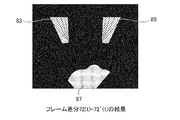
- the position of the pattern drawn on the road surface such as the lane marker 81 shown in FIG. 7B matches on the image. Therefore, as shown in FIG. 7D, the lane marker 81 can be suppressed, that is, removed.
- the own vehicle shadow 87 generated on the road surface is generated at substantially the same position even when the vehicle 10 moves, considering a short time interval in which the frame difference is performed, as shown in FIG. And cannot be removed by the frame difference of the predicted virtual image.
- the result of the frame difference (FIG. 7C) performed by the first frame difference calculation unit 40a is compared with the result of the frame difference (FIG. 7D) performed by the second frame difference calculation unit 40b.
- the second frame difference calculation unit 40b in the vicinity of the detected region, approximately the same feature (for example, shape) by the frame difference performed by the first frame difference calculation unit 40a.
- the area detected by the second frame difference calculation unit 40b is a reflection of the own vehicle shadow 87 generated on the road surface, or a reflection generated on the road surface by the sun or an illumination lamp. .
- region is not an area
- the fact that the region obtained as a result of the frame difference has fallen on the road surface in the direction away from the vehicle 10 refers to the result of edge detection from the virtual image 72 (t). It can be determined by confirming that the edge direction in the region obtained as a result of extending along a radial straight line passing through the installation position P1 (FIG. 6B) of the front camera 12a (FIG. 4).
- the first frame difference result shown in FIG. 7C is binarized with a predetermined threshold value, and a pixel having a gray value larger than the threshold value is detected as a first three-dimensional object candidate region (not shown).
- a pixel having a gray value larger than the threshold value is detected as a first three-dimensional object candidate region (not shown).
- the second frame difference result shown in FIG. 7D is binarized with a predetermined threshold value, and a pixel having a gray value larger than the threshold value is detected as a second three-dimensional object candidate region (not shown).
- the regions of the leg portions 83 and 85 and the own vehicle shadow 87 are detected.
- the non-three-dimensional object whose position moves with the movement of the vehicle that is, the area of the lane marker 81 and the own vehicle shadow 87 can be removed.
- the removal of the non-three-dimensional object can be executed by performing a logical product operation on the detected first three-dimensional object candidate region and the second three-dimensional object candidate region, for example.
- the features used here are not limited to the shape of the region. That is, it is possible to detect areas at positions close to each other using the luminance difference between the areas.
- similarity edge strength, similarity of edge direction
- edge detection is performed on the virtual image 72 (t) by the edge detection unit 40c (FIG. 3). Edge detection is performed by calculating the difference in brightness between adjacent pixels, as is generally done.
- the extending direction of each region is evaluated with reference to the edge detection result of the pixel at the same position as the region. Since the area constituting the three-dimensional object is converted into an area extending radially from the installation position P1 (FIG. 6B) of the front camera 12a (FIG. 4B) toward the periphery of the virtual image 72 (t), the shape or extension of the area is increased. After confirming that the direction meets this condition, it is determined that the direction is an area constituting the three-dimensional object.
- the edge detection result of the virtual image 72 (t) since the area detected by the frame difference is not determined as a solid object area as it is, but the edge detection result of the virtual image 72 (t) is referred to, there is a possibility of being mixed in the result of the frame difference. , The influence of time fluctuation of the exposure characteristics of the camera can be reduced. Further, since the edge detection result of the virtual image 72 (t) is referred to, the three-dimensional object region at time t- ⁇ t can be left as an afterimage, and erroneous detection is suppressed when the three-dimensional object is moving. There is also an effect. Therefore, the detection performance of the three-dimensional object can be further improved.
- solid object regions 90 and 92 that are considered to form a three-dimensional object are detected. Further, the lowermost edge positions of the detected three-dimensional object regions 90 and 92 are detected as road surface contact positions 90a and 92a indicating positions where the three-dimensional object is in contact with the road surface.
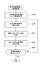
- Step S100 The first frame difference calculation unit 40a performs frame difference.
- Step S110 The second frame difference calculation unit 40b performs frame difference.
- Step S120 The result of step S100 is compared with the result of step S110, and the region that moves with the movement of the vehicle 10 is removed as a non-solid object.
- Step S130 Edge detection of the virtual image 72 (t) is performed.
- Step S140 From the region remaining as a result of Step S120, only the region that has fallen on the road surface in the direction away from the vehicle 10 is detected.
- Step S150 The road surface contact position of the detected area is detected.
- the three-dimensional object area detected from the virtual image 72 is converted into the coordinate system of the original image 70 by performing a reverse overhead conversion.
- the region of the three-dimensional object can be specified within the original image 70 (t).
- the high part of the garage 82 (three-dimensional object) is out of frame, so only the three-dimensional object regions 90 and 92 below the ground are extracted and superimposed. Is done.
- the superimposition here means superimposing the original image 70 as a separate layer.
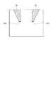
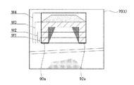
- a rectangular area W1 whose lateral direction circumscribes the three-dimensional object areas 90 and 92 is set in the original image 70 (t).
- the vertical size of the rectangular area W1 is set to a predetermined value.
- a density histogram H (W1) inside the region of the original image 70 (t) corresponding to the rectangular region W1 is created.
- An example of the density histogram H (W1) created in this way is shown in FIG. 9C.
- the rectangular areas W2, W3, and W4 are set by increasing the vertical size of the rectangular area W1 by a predetermined value, and the density histogram H (W2) of the original image 70 (t) corresponding to each rectangular area is set each time. , H (W3), H (W4).
- H (W2), H (W3), and H (W4) generated in this way is shown in FIG. 9C.
- the shading histogram has a similar form. That is, in the example of FIG. 9C, the three-dimensional object regions 90 and 92 are formed from the density histograms H (W1), H (W2), and H (W3) obtained when the rectangular regions W1, W2, and W3 are set. It can be seen that two areas appear, namely a dark area and a bright area constituting a non-three-dimensional object area. Then, it can be seen that the density histogram H (W4) obtained when the rectangular area W4 completely includes the three-dimensional object areas 90 and 92 loses the similarity of the density distribution.
- the similarity between the grayscale histograms H (Wi) is a mode method that assumes the bimodality of the histogram, discriminant analysis, etc. in consideration of the area variation of the three-dimensional object region and the non-three-dimensional object region in the rectangular region Wi. You may evaluate based on stability of the binarization threshold value by.
- two solid object regions may be obtained by setting regions that circumscribe each of the three-dimensional object regions 90 and 92. However, in that case, after extracting each three-dimensional object region, whether or not the three-dimensional object is one lump, for example, the similarity evaluation of the density histogram as in the above-described three-dimensional object region extraction, etc. When it is determined as 1 and it is one lump, it is necessary to integrate as one area.
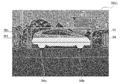
- FIG. 10 shows an original image 70 (t) taken at time t and showing a state in which the other vehicle 11 (three-dimensional object) is stopped in front of the vehicle 10. And the solid-object area
- Step S200 The three-dimensional object region detected from the virtual image 72 is inversely transformed and superimposed on the corresponding position of the original image 70.
- Step S220 A density histogram H (Wi) of an area corresponding to the rectangular area Wi in the original image 70 is generated.
- Step S230 The similarity between a plurality of generated grayscale histograms H (Wi) is calculated, and a set of grayscale histograms H (Wi) having a high similarity is searched. Then, a rectangular area Wi having a maximum vertical size is set as a three-dimensional object area from the set of grayscale histograms H (Wi) determined to have a high degree of similarity.
- Step S240 It is determined whether or not a three-dimensional object area has been set. When the three-dimensional object area is set, the process of FIG. 11 is terminated. Otherwise, the process returns to step S210, and the process for another three-dimensional object candidate area is repeated.
- FIG. 11 shows an example of the three-dimensional object region extraction process.
- the three-dimensional object region may be extracted using other features such as the edge detection result of the virtual image as well as the similarity of the density histogram H (Wi) of the region.
- Solid objects on the road surface are not always grounded at the lower end. That is, there may be a floating region that is not grounded on the road surface.
- the garage 82 three-dimensional object described in FIGS. 6A and 6B
- only the leg portions 83 and 85 are in contact with the road surface, and the region sandwiched between the leg portions 83 and 85 is floating from the road surface.
- the other vehicle 11 three-dimensional object illustrated in FIG. 10
- only the tire is in contact with the road surface, and the other part (the vehicle body part) is floating from the road surface.
- the road surface projection in which the other vehicle 11 that is the three-dimensional object region extracted by the above-described three-dimensional object region extraction process is projected onto the road surface from directly above. Calculate the position. This process is performed in the road surface projection position calculation unit 50b of FIG. By this process, it is possible to detect whether or not there is a part floating from the road surface in the extracted three-dimensional object region.
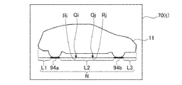
- the floating part is detected by setting a line segment L including road surface contact positions 94a and 94b and extending to the left and right ends of the other vehicle 11 which is the detected three-dimensional object region. Then, from the position of the line segment L, the position of a point that abuts against the other vehicle 11 that is a three-dimensional object region is detected upward on the original image 70 (t).
- a point Qi floating in the space is detected.
- a point Qj floating in the space is detected.
- the road surface contact positions 94a and 94b are in contact with the road surface, they are excluded from the processing target.
- the road surface ground positions 94a and 94b are directly used as road surface ground points.
- the road surface contact points Ri, Rj,... Set in this way represent road surface projection positions where the other vehicle 11 (three-dimensional object) is projected onto the road surface from directly above. Then, among the road surface contact points Ri, Rj,... Obtained in this way, road surface contact points continuously detected on the left and right are connected to each other, and road surface contact lines L1, L2, which are one line segment, are connected. L3 is formed.
- the vehicle 10 can approach the other vehicle 11 (three-dimensional object) at least up to the position of the road surface ground lines L1, L2, and L3. If the vehicle 10 approaches the other vehicle 11 beyond the road surface ground lines L1, L2, L3, the vehicle 10 may come into contact with the other vehicle 11.
- the road surface grounding positions 94a and 94b are integrated as one road surface grounding line N.
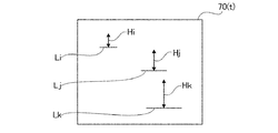
- a three-dimensional view is taken at any position above the road surface ground lines Li, Lj, Lk (corresponding to the road surface ground line N) detected in the original image 70 (t). Check if the object area is floating.
- whether or not the vehicle 10 can enter beyond the road surface ground lines Li, Lj, and Lk depends on whether the road surface ground lines Li, Lj, and Lk are longer than the width of the vehicle 10 and the road surface ground line. This can be determined by confirming that there is a space exceeding the height of the vehicle 10 above Li, Lj, and Lk.
- the original image 70 (t) is generated by being subjected to a perspective transformation so that the farther away the original image 70 (t), the shorter it appears above the image.
- the actual road surface ground lines Li, Lj, and Lk are determined by the vertical position and length of the road surface ground lines Li, Lj, and Lk detected inside the original image 70 (t) on the original image 70 (t).
- the length can be estimated.
- the height of the space where the vehicle 10 can enter at the position of the road surface ground line can be estimated from the vertical position of the road surface ground lines Li, Lj, and Lk on the original image 70 (t).
- the vehicle 10 enters beyond the road surface ground lines L1, L2, and L3.
- the heights Hi, Hj, Hk of the spaces above the road surface ground lines Li, Lj, Lk required for the above can be estimated based on the vertical positions of the road surface ground lines Li, Lj, Lk, respectively.
- the actual length of each road surface ground line Li, Lj, Lk and the height Hi, Hj, Hk of the space above each road surface ground line Li, Lj, Lk are the installation layout of the front camera 12a (FIG. 4), respectively. It can be estimated based on information (camera height, camera depression angle, lens parameters). That is, since the installation layout of the front camera 12a (FIG. 4) is known in advance, the actual length of each road ground line L1, L2, L3 and the height of the space above each road ground line L1, L2, L3. H1, H2, and H3 can be obtained in advance by calculation. And the calculated value is memorize
- each road surface ground line Li, Lj, Lk is a value exceeding the width of the vehicle 10, and It can be determined whether or not there is a space exceeding the height of the vehicle 10 above the road surface ground lines Li, Lj, and Lk.
- Step S300 The road surface projection position of the three-dimensional object region is calculated as road surface contact points Ri, Rj,. Details of the processing are as described above.
- Step S310 Out of the road surface contact points Ri, Rj,..., Continuous points are integrated into a road surface contact line N. Then, the length of the road surface ground line N and the vertical position of the road surface ground line N on the original image 70 are calculated.
- Step S320 The height H of the space above the road surface ground line N is calculated.
- Step S330 It is determined whether or not the vehicle 10 can enter the road surface ground line N.
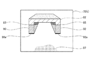
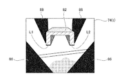
- FIG. 14A is an example of the display image 74 (t) generated from FIGS. 6A and 6B.
- This display image 74 (t) is displayed on the monitor 150 (FIG. 4) of the vehicle 10.
- road surface ground lines L1 and L2 are drawn with bold lines on the virtual image 72 (t) (overhead image) and correspond to the extracted garage 82.
- the three-dimensional object area is displayed in a superimposed manner. Since the vehicle 10 can enter the area between the road surface ground lines L1 and L2, no thick line is drawn at the position of the road surface ground line.
- the driver of the vehicle 10 sees the display image 74 (t) and determines that the vehicle 10 can enter the back of the garage 82 (three-dimensional object).
- the visibility may be improved by giving a predetermined color such as red to the thick lines indicating the road surface ground lines L1 and L2.
- a predetermined gray value (for example, 0) is stored in the invisible area 86 that is outside the field of view of the front camera 12a and the invisible area 88 that is behind the garage 82 (three-dimensional object). .
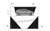
- FIG. 14B is an example of a display image 75 (t) generated when the original image 70 (t) shown in FIG. 10 is observed.
- a thick line indicating the road surface ground line N is drawn below the other vehicle 11. Then, it is indicated that the vehicle 10 can only approach the position of the road surface ground line N, that is, the vehicle 10 cannot enter beyond the road surface ground line N.
- the display form of the display image 74 (t) is not limited to the example shown in FIGS. 14A and 14B. That is, a thick line may be displayed in a range where the vehicle 10 can enter instead of a range where the vehicle 10 cannot enter in the road surface ground line N.
- the road surface around the vehicle 10 captured by the front camera 12a is displayed.
- the original image 70 including the image conversion unit 30 converts the virtual image 72 (overhead image) viewed from a predetermined viewpoint position, and the three-dimensional object detection unit 40 increases the height from the road surface in the virtual image 72.
- the vehicle entry availability determination unit 50 determines whether the vehicle 10 can enter the inside of the detected three-dimensional object or the gap between different three-dimensional objects. Even if it is a three-dimensional object, since it can be determined whether or not the vehicle 10 can enter the space, contact with the three-dimensional object can be prevented in advance.
- the three-dimensional object region extraction unit 50a extracts a region corresponding to a three-dimensional object from the original image 70. Then, the road surface projection position calculation unit 50b configures the three-dimensional object region with respect to the three-dimensional object region extracted by the three-dimensional object region extraction unit 50a, and the presence or absence of the floating region that is not grounded on the road surface and the road surface of the floating region And a road surface projection position obtained by projecting the floating region onto the road surface from directly above, and the vehicle accessible space identifying unit 50c determines the road surface projection position calculated by the road surface projection position calculation unit 50b.
- the presence / absence of the floating region and its road surface are determined by a simple process to identify whether there is a space in which the vehicle 10 can enter in the interior of the three-dimensional object or in the gap between different three-dimensional objects.
- Throw Position can be calculated.
- the vehicular admission / prohibition range display unit 60 is not allowed to enter the vehicle 10 in the vehicular admission / rejection determination unit 50.
- the inaccessible range determined to be or the inaccessible range in which the vehicle 10 is determined to be able to enter in a superimposed manner on the road surface position of the virtual image 72 there is a floating area that is not grounded on the road surface. Even a three-dimensional object can visualize how far the vehicle 10 can approach the three-dimensional object, and can prevent contact with the three-dimensional object.
- the three-dimensional object detection unit 40 captures images at different times calculated by the first frame difference calculation unit 40a.
- the conversion source of the other virtual image 72 (t) predicted based on the movement amount and movement direction of the vehicle 10 from one virtual image 72 (t ⁇ t) of the two virtual images (overhead view images)
- On the road surface based on the difference result and The solid object on the road surface was detected by removing the object and referring to the edge information of the virtual image 72 (t) detected by the edge detection unit 40c. Therefore, by a simple image processing, a three-dimensional object having a
- the edge detection unit 40c When it is determined that the detected area is falling on the road surface in a direction away from the vehicle 10 based on the detection result, the area is detected as an area representing a three-dimensional object on the road surface. Therefore, by referring to the edge detection result of the virtual image 72 (t), it is possible to reduce the influence of temporal variations in illumination, shadow, and camera exposure characteristics that may be mixed into the frame difference result. The detection performance of the three-dimensional object can be further improved.
- Example 1 although demonstrated using the example which installed one front camera 12a as the imaging part 12, the camera to be used is not limited to one.
- a vehicular entry propriety determination device capable of monitoring the entire periphery of the vehicle 10 by installing a plurality of cameras toward the front, left, right, and rear of the vehicle 10.
- the original image captured by each camera is converted into a virtual image (overhead image) and then combined into a single composite image, and each process described in the embodiment is performed on the composite image. Done.
- Example 1 Although the example which judges whether the entrance of the vehicle 10 to the inside of the garage 82 which is one solid object, or the other vehicle 11 was shown, this is approaching into the inside of a single solid object. It is not limited to the example which makes a judgment. That is, when two vehicles are parked at intervals in a parking lot where no parking frame is displayed, it is determined whether or not the vehicle 10 can enter and park in the space between them. It can be applied to any scene.
- the lateral width and the height of the space existing between the two detected three-dimensional object regions are respectively calculated, and the calculated space
- the size of the vehicle (width and height) and the dimensions of the vehicle 10 are compared to determine whether the vehicle 10 can enter.
- the image processing procedure described in the first embodiment need not be as described in the first embodiment.
- the garage 82 is reflected in the virtual image 72 (t) without interruption, the garage 82 is detected as one solid object region from the virtual image 72 (t).
- the procedure may be followed to calculate the height H of the space above the road surface ground line N. .
- the road surface ground line N of the detected three-dimensional object is obtained, and only the range in which the vehicle 10 cannot enter the road surface ground line N is obtained.
- the vehicle 10 can be automatically parked based on information on a range in which the vehicle 10 can enter in the calculated road ground line N.
- the three-dimensional object is detected by performing the frame difference between the virtual images.
- the frame difference performed at this time is the frame difference between the gray values representing the brightness of the virtual image. It is not limited. That is, for example, edge detection of a virtual image may be performed and a frame difference between virtual images in which detected edge strengths are stored may be performed, or a frame difference between virtual images in which detected edge directions are stored may be calculated. The region where the change has occurred may be detected. Further, the virtual image may be divided into a plurality of small blocks, and the similarity of the density histogram of each small block or the histogram of the edge detection result may be used.
Landscapes
- Engineering & Computer Science (AREA)
- Physics & Mathematics (AREA)
- General Physics & Mathematics (AREA)
- Theoretical Computer Science (AREA)
- Multimedia (AREA)
- Computer Vision & Pattern Recognition (AREA)
- Mechanical Engineering (AREA)
- Signal Processing (AREA)
- Geometry (AREA)
- Closed-Circuit Television Systems (AREA)
- Image Analysis (AREA)
- Image Processing (AREA)
Abstract
車両周辺で検出された立体物に対する、車両の進入可否を判定する。 前方カメラ(12a)で撮像された車両(10)の周囲の路面を含む原画像(70)を、画像変換部(30)が、所定の視点位置から見た仮想画像(72)に変換して、立体物検出部(40)が、仮想画像(72)の中から、路面から高さを有する立体物を検出して、車両進入可否判定部(50)が、検出された立体物の内部または異なる立体物の間隙への車両(10)の進入可否を判定する。
Description
本発明は車両に取り付けられたカメラで撮影された車両周囲の画像を処理する装置、特に、車両周囲の画像を俯瞰画像に変換して処理することを前提としたものである。
車両周囲の画像を、座標変換して俯瞰画像に変換して表示したときには、立体物は歪んで表示されるため、俯瞰画像を見ただけでは、その立体物にどこまで接近できるかを把握することが困難であった。そのため、例えば、俯瞰変換した画像上で、俯瞰変換により発生する立体物の歪を補正して表示する装置が提案されている(例えば、特許文献1)。
しかしながら、特許文献1に記載された車両周辺画像表示装置では、路面上に存在する立体物の外形の歪みは補正できるものの、その立体物の一部が路面に接地していない場合には、立体物のうち空中に浮かんだ部位は、俯瞰画像に変換されたときに、車両から遠ざかる方向に、路面上に倒れ込むように変形されて投影されるため、俯瞰画像を頼りにして、車両をその立体物の近傍まで接近させると、立体物に接触してしまう虞があった。さらに、その立体物が、車庫のように本来車両が進入すべき場所であるときには、俯瞰画像を見ただけで、車両が進入可能か否かを判定することができないという問題があった。
本発明は、上記課題に鑑みてなされたもので、車両周囲の路面上で検出された立体物に対して、車両が進入可能な空間の有無を判断して車両が進入可能であるか否かを判定するものである。
前記課題を解決するために、本発明に係る車両用進入可否判定装置は、車両に取り付けられた、前記車両の周囲の路面を含む範囲を撮像する撮像部と、前記撮像部で撮像された原画像を、所定の視点位置から見た仮想画像に変換する画像変換部と、前記仮想画像の中から、路面から高さを有する立体物を検出する立体物検出部と、前記立体物の内部または異なる前記立体物の間隙への前記車両の進入可否を判定する車両進入可否判定部と、を有することを特徴とする。
このように構成された本発明に係る車両用進入可否判定装置によれば、前記した構成とすることによって、車両の周囲に存在する、空中に浮かんだ部位を有する立体物や、オーバーハング部を有する立体物のように、地面に接地していない浮遊領域を有する立体物と車両との接触可否を判定することができる。したがって、立体物に対する車両の進入可否および車両が接近可能な位置を運転者に提示することができるため、車両の立体物への接触を防止することができる。
以下、本発明に係る車両用進入可否判定装置の実施形態について、図面を参照して説明する。
(実施例1)
本実施例は、本発明を、車両の周囲にある立体物を検出するとともに、検出された立体物に対して、車両が進入可能か否かを判定して、その結果を運転者に伝達する車両用進入可否判定装置として適用したものである。
本実施例は、本発明を、車両の周囲にある立体物を検出するとともに、検出された立体物に対して、車両が進入可能か否かを判定して、その結果を運転者に伝達する車両用進入可否判定装置として適用したものである。
(全体構成の説明)
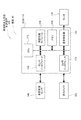
まず、図1から図3を用いて本実施例の機能構成を説明する。本実施例に係る車両用進入可否判定装置100は、図1に示すように、車両10に搭載されて、車両10の前方の路面を含む画像を撮像する撮像部12と、撮像部12から出力された画像信号を、計算機で取り扱えるデジタル画像形式の原画像70に変換する画像入力部20と、原画像70を、所定の視点位置から見た仮想画像72に変換する画像変換部30と、仮想画像72の中から、路面から高さを有する立体物を検出する立体物検出部40と、検出された立体物の内部または検出された複数の立体物の間隙への車両10の進入可否を判定する車両進入可否判定部50と、車両進入可否判定部50における車両進入可否判定の結果、進入不可または進入可能と判定された範囲を表示する車両進入可否範囲表示部60と、から構成されている。
まず、図1から図3を用いて本実施例の機能構成を説明する。本実施例に係る車両用進入可否判定装置100は、図1に示すように、車両10に搭載されて、車両10の前方の路面を含む画像を撮像する撮像部12と、撮像部12から出力された画像信号を、計算機で取り扱えるデジタル画像形式の原画像70に変換する画像入力部20と、原画像70を、所定の視点位置から見た仮想画像72に変換する画像変換部30と、仮想画像72の中から、路面から高さを有する立体物を検出する立体物検出部40と、検出された立体物の内部または検出された複数の立体物の間隙への車両10の進入可否を判定する車両進入可否判定部50と、車両進入可否判定部50における車両進入可否判定の結果、進入不可または進入可能と判定された範囲を表示する車両進入可否範囲表示部60と、から構成されている。
撮像部12は、図2に示すように車両10の前方に取り付けられており、車両10の直近の路面を含む前方観測範囲14の内部を、約180°の視野範囲に亘って撮像する。
立体物検出部40は、詳しくは、図3に示すように、所定の時間間隔を隔てて撮像部12(図1)で撮像されて画像変換部30(図1)で画像変換された、異なる時刻に得られた2枚の原画像70(t),70(t-Δt)から生成された2枚の仮想画像72(t),72(t-Δt)のフレーム差分を行う第1フレーム差分演算部40aと、時刻(t-Δt)に得られた原画像70(t-Δt)から生成された仮想画像72(t-Δt)から、時刻tにおける予測仮想画像72’(t)を生成して、時刻tにおいて実際に得られた仮想画像72(t)から予測仮想画像72’(t)を差し引くフレーム差分を行う第2フレーム差分演算部40bと、仮想画像72(t)の中から、隣接する画素の間で明るさの変化が大きい画素、すなわち、エッジを構成する画素を検出するエッジ検出部40cと、第1フレーム差分演算部40a,第2フレーム差分演算部40bの演算結果とエッジ検出部40cの検出結果に基づいて立体物を構成すると考えられる領域を検出する立体物領域クラスタリング部40dと、からなる。
車両進入可否判定部50は、詳しくは、図1に示すように、原画像70の中から、立体物検出部40で検出された立体物に対応する領域を抽出する立体物領域抽出部50aと、立体物領域抽出部50aで抽出された立体物領域に対して、車両がその立体物に接近できる限界位置を示す路面投影位置を算出する路面投影位置算出部50bと、立体物の内部または異なる立体物の間隙に車両10が進入可能な空間があるか否かを識別する車両進入可能空間識別部50cと、からなる。
次に、図4を用いて本実施例のハードウェア構成を説明する。本実施例に係る車両用進入可否判定装置100は、車両10に搭載されて、必要な画像処理や演算処理を行うECU(電子制御ユニット)110と、ECU110に接続された、撮像部12(図1)を構成する前方カメラ12aと、車両10の挙動を検出することによって、車両10の移動量と移動方向を算出する、操舵角センサや距離センサで構成された車両状態センサ140と、車両進入可否範囲表示部60(図1)の処理結果を表示するモニタ150と、から構成されている。
ECU110は、さらに、必要なデータの送受信やプログラムの実行を行うCPU112と、CPU112に接続された、前方カメラ12aの制御を行うカメラインタフェース114と、車両状態センサ140の測定結果を取得するセンサインタフェース116と、内部に内蔵された所定のプログラムによって画像処理を実行する画像処理モジュール118と、画像処理の中間結果や、必要な定数、プログラム等を記憶するメモリ120と、モニタ150の制御を行う表示制御部122と、からなる。
なお、図1で説明した画像入力部20,画像変換部30,立体物検出部40,車両進入可否判定部50,車両進入可否範囲表示部60は、それぞれ、後述する作用を実現するソフトウェアによって制御されている。このソフトウェアは、前記したメモリ120の内部に記憶されて、必要に応じて適宜実行される。なお、ソフトウェアは、必要に応じて、CPU112や画像処理モジュール118の内部に記憶しておいてもよい。
(車両用進入可否判定装置で行われる処理の流れの説明)
ここで、車両用進入可否判定装置100で行われる一連の処理の流れについて、図5のフローチャートを用いて説明する。なお、ここでは各処理の概要を説明するに留め、処理内容の詳細な説明は後述する。
ここで、車両用進入可否判定装置100で行われる一連の処理の流れについて、図5のフローチャートを用いて説明する。なお、ここでは各処理の概要を説明するに留め、処理内容の詳細な説明は後述する。
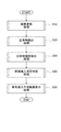
(ステップS10)画像変換処理を行う。具体的には、撮像された原画像を仮想画像に変換する。
(ステップS20)立体物検出処理を行う。具体的な処理の内容は後述する。
(ステップS30)立体物領域抽出処理を行う。具体的な処理の内容は後述する。
(ステップS40)車両進入可否判定処理を行う。具体的な処理の内容は後述する。
(ステップS50)車両進入不可範囲表示処理を行う。具体的な処理の内容は後述する。
以下、車両用進入可否判定装置100で行われる各処理の内容について、順を追って説明する。
(画像変換処理の説明)
まず、図1と、図6A,図6Bを用いて、画像変換処理の作用について説明する。画像変換処理は、図1に記載した撮像部12と画像入力部20と画像変換部30において行われる。
まず、図1と、図6A,図6Bを用いて、画像変換処理の作用について説明する。画像変換処理は、図1に記載した撮像部12と画像入力部20と画像変換部30において行われる。
具体的には、撮像部12を構成する前方カメラ12a(図4)の出力を、画像入力部20においてデジタル画像に変換して、図6Aに示す原画像70として画像変換部30に入力する。なお、時刻tに撮像された原画像を70(t)と表記する。
図6Aに示す原画像70(t)は、車両10(図1)の前方の路面80を撮像したものである。路面にはレーンマーカ81が引かれており、そのレーンマーカの奥に、車両10を駐車するガレージ82(立体物)が設置されている。このガレージ82は、左右にそれぞれ脚部83,85を有している。なお、原画像70(t)の下部には、車両10の影である自車影87が映っている。
画像変換部30は、図6Aに示す原画像70(t)を、画像変換部30において、図6Bに示すように、車両10を真上から見下ろした仮想画像72(t)(俯瞰画像)に変換する。具体的な変換方法の説明は省略するが、前方カメラ12a(図4)の設置レイアウト情報(カメラの高さ,カメラの俯角,レンズパラメータ)を用いて、原画像70(t)を、車両10が存在する路面に投影する座標変換を行うことによって、仮想画像72(t)が得られる。なお、原画像70(t)が変換された仮想画像を、72(t)と表記することにする。
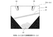
仮想画像72(t)を生成する際、前方カメラ12aで撮像された原画像70(t)に映ったガレージ82(立体物)のうち、左右の脚部83,85の部分が、仮想画像72(t)上で上方に向かって、すなわち、車両10から遠ざかる方向に、路面上に倒れ込むように変形されて映り込む。そして、仮想画像72(t)の上方ほど、脚部83,85の横幅が広くなるように変形される。こうした脚部83,85の変形、すなわち路面から高さを有する領域の変形は、前方カメラ12a(図4)の設置位置P1(図6B)から、仮想画像72(t)の周辺に向かって放射状に広がるように発生する。
また、仮想画像72(t)には、前方カメラ12aの視野外となる不可視領域86,86が発生するため、この不可視領域86,86には、所定の濃淡値(例えば0)を格納しておく。
(立体物検出処理の概要説明)
次に、図3と、図7Aから図7Eを用いて、立体物検出処理の作用について説明する。なお、立体物検出処理は、図3の立体物検出部40において行われる。
次に、図3と、図7Aから図7Eを用いて、立体物検出処理の作用について説明する。なお、立体物検出処理は、図3の立体物検出部40において行われる。
立体物検出部40は、図7A,図7Bに示すように、時間間隔Δtを隔てて撮像された2枚の原画像からそれぞれ生成された仮想画像の中から立体物を検出する。ここでは、時刻tで撮像された原画像70(t)から生成された仮想画像72(t)と、時刻t-Δtで撮像された原画像70(t-Δt)から生成された仮想画像72(t-Δt)から、立体物を検出するものとして説明を行う。
まず、図7Cに示すように、2枚の仮想画像72(t),72(t―Δt)のフレーム差分を計算する。この処理は、図3の第1フレーム差分演算部40aで行われる。
次に、図7Dに示すように、仮想画像72(t―Δt)から時刻tにおける仮想画像72(t)を予測して予測仮想画像72’(t)を生成し、この予測仮想画像72’(t)と時刻tにおいて実際に得られた仮想画像72(t)とのフレーム差分を計算する。この処理は、図3の第2フレーム差分演算部40bで行われる。
予測仮想画像72’(t)は、具体的には次のようにして生成する。すなわち、車両状態センサ140(図4)によって、時間間隔Δtの間における車両10の移動量と移動方向を随時計測する。そして、計測された時間間隔Δtの間の車両10の移動量と移動方向に対応するように、仮想画像72(t―Δt)を平行移動および回転移動させて、時刻tにおける予測仮想画像72’(t)を生成する。なお、このとき、仮想画像72(t―Δt)には全て路面が映っているものと仮定して予測仮想画像72’(t)を生成する。
なお、第2フレーム差分演算部40bで行うフレーム差分は、時刻tにおける仮想画像72(t)に基づいて、時刻t-Δtにおける仮想的な予測仮想画像72’(t―Δt)を生成した後で、この予測仮想画像72’(t―Δt)と、時刻(t-Δt)において実際に得られた仮想画像72(t―Δt)と、の間で行っても構わない。
このように仮想画像72(t)と予測仮想画像72’(t)のフレーム差分を行うことによって、図7Bに示したレーンマーカ81のような路面に描かれたパターンの位置が画像上で一致するため、図7Dに示すように、レーンマーカ81を抑制、すなわち除去することができる。一方、路面上に生じた自車影87は、フレーム差分を行う短い時間間隔の間で考えると、車両10が移動してもほぼ同じ位置に発生するため、図7Dに示すように、仮想画像と予測仮想画像のフレーム差分によって除去することができない。
これに対して、異なる2つの時刻で得た実際の仮想画像72(t),72(t―Δt)同士のフレーム差分によると、図7Cに示すように、ほぼ同じ位置に発生する自車影87を除去することができる。ただし、レーンマーカ81のように路面に描かれたパターンは、車両10の移動に伴ってその観測位置が移動するため、フレーム差分によって除去することができない。
ここで、第1フレーム差分演算部40aで行ったフレーム差分の結果(図7C)と、第2フレーム差分演算部40bで行ったフレーム差分の結果(図7D)を比較する。
まず、第2フレーム差分演算部40bで行ったフレーム差分の結果、検出された領域のうち、その領域の近傍に、第1フレーム差分演算部40aで行ったフレーム差分によって略同じ特徴(例えば形状)を有する領域が検出されないときには、第2フレーム差分演算部40bで検出された領域は、路面上に生じた自車影87や、太陽や照明灯によって路面に生じる照り返しであると推測することができる。そして、その領域は立体物を示す領域ではないと判断して除去する。
次に、前記判断で残った領域のうち、車両10から遠ざかる方向に、路面上に倒れ込んだ領域のみを、路面上にある高さを有する立体物であるとして検出する。すなわち、図7C,図7Dの例では、脚部83,85の領域のみが検出される。
なお、フレーム差分を行った結果得られた領域が、車両10から遠ざかる方向に、路面上に倒れ込んでいることは、仮想画像72(t)からエッジ検出を行った結果を参照して、フレーム差分の結果得られた領域におけるエッジ方向が、前方カメラ12a(図4)の設置位置P1(図6B)を通る放射状の直線に沿って延びていることを確認して判断することができる。
(立体物検出処理の詳細説明)
次に、立体物検出処理の具体的な内容について、図7Cから図7Eを用いて説明する。
次に、立体物検出処理の具体的な内容について、図7Cから図7Eを用いて説明する。
まず、図7Cに示す第1フレーム差分結果を所定のしきい値で2値化して、しきい値よりも大きい濃淡値を有する画素を第1立体物候補領域(非図示)として検出する。この処理によって、脚部83,85やレーンマーカ81の領域が検出される。
次に、図7Dに示す第2フレーム差分結果を所定のしきい値で2値化して、しきい値よりも大きい濃淡値を有する画素を第2立体物候補領域(非図示)として検出する。この処理によって、脚部83,85や自車影87の領域が検出される。
そして、検出された第1立体物候補領域と第2立体物候補領域に対して、互いに近接した位置にあって同じ形状(特徴)を有する領域のみを選出する、いわゆる非立体物の除去を行う。この処理によって、車両の移動とともにその位置が移動する非立体物、すなわち、レーンマーカ81や自車影87の領域を除去することができる。この非立体物の除去は、例えば、検出された第1立体物候補領域と第2立体物候補領域に対して論理積演算を行うことによって実行できる。
なお、ここで利用する特徴は、領域の形状に限るものではない。すなわち、領域の輝度差を利用して、互いに近接した位置にある領域を検出してもよい。また、特徴として、仮想画像に対してエッジ検出を行った結果の類似性(エッジ強度,エッジ方向の類似性)や、仮想画像を複数の小ブロックに分割して、各小ブロックから得た、濃淡ヒストグラムやエッジ検出結果のヒストグラムの類似性等を用いてもよい。
次に、仮想画像72(t)に対して、エッジ検出部40c(図3)でエッジ検出を行う。エッジ検出は、一般的に行われているように、隣接する画素間の明るさの差を演算することによって行う。
非立体物の除去を行って残った領域に対して、その領域と同じ位置にある画素のエッジ検出結果を参照して、各領域の延びる方向を評価する。立体物を構成する領域は、前方カメラ12a(図4)の設置位置P1(図6B)から仮想画像72(t)の周辺に向かって放射状に延びる領域に変換されるため、領域の形状や延びる方向が、この条件に合致することを確認して、立体物を構成する領域であると判断する。
このとき、フレーム差分で検出された領域をそのまま立体物領域と判断せず、仮想画像72(t)のエッジ検出結果を参照するため、フレーム差分の結果に混入する可能性がある、照明,影,カメラの露光特性の時間変動の影響を低減することができる。また、仮想画像72(t)のエッジ検出結果を参照するため、時刻t-Δtにおける立体物領域が残像として残らない状態とすることができるとともに、立体物が移動していた場合の誤検出抑制効果もある。したがって、立体物の検出性能をより一層向上させることができる。
この一連の処理によって、例えば図7Eに示すように、立体物を構成すると考えられる立体物領域90,92が検出される。そして、さらに、検出された立体物領域90,92の最下部の辺縁位置を、立体物が路面に接地している位置を示す路面接地位置90a,92aとして検出する。
(立体物検出処理の流れの説明)
次に、図8のフローチャートを用いて、立体物検出処理の一連の流れを説明する。
次に、図8のフローチャートを用いて、立体物検出処理の一連の流れを説明する。
(ステップS100)第1フレーム差分演算部40aでフレーム差分を行う。
(ステップS110)第2フレーム差分演算部40bでフレーム差分を行う。
(ステップS120)ステップS100の結果と、ステップS110の結果を比較して、車両10の移動とともに移動する領域を非立体物として除去する。
(ステップS130)仮想画像72(t)のエッジ検出を行う。
(ステップS140)ステップS120の結果残った領域の中から、車両10から遠ざかる方向に、路面上に倒れ込んだ領域のみを検出する。
(ステップS150)検出された領域の路面接地位置を検出する。
(立体物領域抽出処理の説明)
次に、仮想画像72(俯瞰画像)の中から検出された立体物に対して、その立体物と対応する領域を原画像70の中から抽出する。この処理は、立体物領域抽出部50a(図1)で行われる。以下、図9Aから図9Cを用いて、立体物領域抽出処理の作用について説明する。
次に、仮想画像72(俯瞰画像)の中から検出された立体物に対して、その立体物と対応する領域を原画像70の中から抽出する。この処理は、立体物領域抽出部50a(図1)で行われる。以下、図9Aから図9Cを用いて、立体物領域抽出処理の作用について説明する。
仮想画像72の中から検出された立体物領域を、仮想画像72を作成したときとは逆に、逆俯瞰変換して原画像70の座標系に変換する。この逆俯瞰変換によって、図9Aに示すように、原画像70(t)の内部において立体物の領域を特定することができる。ただし、図9Aの場合、仮想画像に変換した際に、ガレージ82(立体物)の高所部分はフレームアウトしてしまうため、地面に近い下方の立体物領域90,92のみが抽出されて重畳される。なお、原画像70に格納された濃淡値はこの後の処理で利用するため、ここでいう重畳とは、原画像70の上に別のレイヤーとして重ね合わせることを意味している。
次に、図9Bに示すように、原画像70(t)の中に、横方向が立体物領域90,92に外接するような矩形領域W1を設定する。矩形領域W1の縦方向サイズは、予め設定した所定の値とする。そして、立体物領域抽出部50aにおいて、矩形領域W1に対応する原画像70(t)の領域内部の濃淡ヒストグラムH(W1)を作成する。このようにして作成された濃淡ヒストグラムH(W1)の例を図9Cに示す。
図9Cからわかるように、濃淡ヒストグラムH(W1)には、立体物領域90,92を形成している暗部領域と、非立体物領域を構成している明部領域の2つの領域が出現している。
そして、矩形領域W1の縦方向サイズを所定値ずつ増加させて矩形領域W2,W3,W4を設定して、その都度、各矩形領域に対応する原画像70(t)の濃淡ヒストグラムH(W2),H(W3),H(W4)を作成する。このようにして生成された濃淡ヒストグラムH(W2),H(W3),H(W4)の例を図9Cに示す。
図9Cからわかるように、矩形領域と立体物領域90,92とが重複していると、濃淡ヒストグラムは類似の形態をなす。すなわち、図9Cの例では、矩形領域W1,W2,W3を設定したときに得られる濃淡ヒストグラムH(W1),H(W2),H(W3)から、立体物領域90,92を形成している暗部領域と、非立体物領域を構成している明部領域の2つの領域が出現することがわかる。そして、矩形領域W4が立体物領域90,92を完全に包含したときに得られる濃淡ヒストグラムH(W4)は、濃淡分布の類似性が崩れることがわかる。
本実施例では、図9Cに示すように、異なる縦方向サイズを有する複数の矩形領域Wi(i=1,2,…)を設定して、その矩形領域Wi内の濃淡ヒストグラムH(Wi)を作成し、作成された濃淡ヒストグラムH(Wi)の類似性を評価して、原画像70(t)の中から立体物に対応する領域を抽出する。
なお、濃淡ヒストグラムH(Wi)間の類似性を評価する尺度としては、例えば、ユークリッド距離による判別法、ヒストグラム交差法等の様々な方法が提案されており、それらのいずれの尺度を用いて評価しても構わない。ただし、設定する矩形領域Wi(i=1,2,…)はそれぞれサイズが異なっているため、作成された濃淡ヒストグラムH(Wi)の総面積は全て異なっている。したがって、類似性を算出するためには、濃淡ヒストグラムH(Wi)の総面積が等しくなるように、予め正規化処理を行っておく必要がある。なお、濃淡ヒストグラムH(Wi)間の類似性は、矩形領域Wi内の立体物領域と非立体物領域の面積変動を考慮して、ヒストグラムの双峰性を仮定したモード法や、判別分析等による2値化閾値の安定性に基づいて評価しても構わない。
さらに、図9Bの例では、立体物領域90,92(図9A)にともに外接する矩形領域Wi(i=1,2,…)を設定したが、これは、立体物領域90と立体物領域92の間に、空中に浮遊した浮遊領域が存在するものと仮定したためである。
したがって、立体物領域90,92にそれぞれ外接する領域を設定して、2つの立体物領域をそれぞれ求めても構わない。ただし、その場合には、立体物領域をそれぞれ抽出した後で、それらの立体物が1つの塊であるか否かを、例えば、前述した立体物領域抽出と同様に濃淡ヒストグラムの類似性評価等によって判定して、ひとつの塊であったときには、1つの領域として統合する必要がある。
次に、図10に立体物領域を抽出した別の例について説明する。図10は、時刻tに撮像された、車両10の前方に他車両11(立体物)が停止している状態を示す原画像70(t)を示している。そして、立体物検出によって検出された立体物領域94が、原画像70(t)に重畳された状態を示している。そして、他車両11(立体物)のタイヤの接地位置が、路面接地位置94a,94bとして検出されている。
図10に示した原画像70(t)に対して、前述した立体物領域抽出処理を行う。すなわち、立体物領域94に外接する矩形領域Wi(i=1,…,n)を設定して、濃淡ヒストグラムH(Wi)の類似度を評価する。これによって、他車両11に外接する矩形領域Wnを抽出することができる。
(立体物領域抽出処理の流れの説明)
以下、図11のフローチャートを用いて、立体物領域抽出処理の一連の流れを説明する。
以下、図11のフローチャートを用いて、立体物領域抽出処理の一連の流れを説明する。
(ステップS200)仮想画像72の中から検出された立体物領域を逆変換して原画像70の対応する位置に重畳する。
(ステップS210)立体物候補領域として、横方向が、原画像70に重畳された立体物領域に外接するような複数の矩形領域Wi(i=1,2,…)を設定する。
(ステップS220)原画像70のうち、矩形領域Wiに対応する領域の濃淡ヒストグラムH(Wi)を生成する。
(ステップS230)生成された複数の濃淡ヒストグラムH(Wi)同士の類似度を算出して、類似度の高い濃淡ヒストグラムH(Wi)の組を探す。そして、類似度が高いと判定された濃淡ヒストグラムH(Wi)の組のうち、縦方向サイズが最大の矩形領域Wiを立体物領域として設定する。
(ステップS240)立体物領域が設定されたか否かを判定する。立体物領域が設定されたときは図11の処理を終了して、それ以外のときはステップS210に戻り、別の立体物候補領域に対する処理を繰り返す。
なお、図11は、立体物領域抽出処理の一例を示すものである。実際には、前述したように、領域の濃淡ヒストグラムH(Wi)の類似度のみならず、仮想画像のエッジ検出結果等、別の特徴を用いて立体物領域を抽出してもよい。
(車両進入可否判定処理の説明)
次に、図12Aから図12Cを用いて、車両進入可否判定処理の作用について説明する。車両進入可否判定処理は、図1に示した車両進入可否判定部50において行われる。
次に、図12Aから図12Cを用いて、車両進入可否判定処理の作用について説明する。車両進入可否判定処理は、図1に示した車両進入可否判定部50において行われる。
路面上の立体物は、その下端部が全て路面に接地しているとは限らない。すなわち、路面に接地していない浮遊領域を有している場合もある。例えば、図6A,図6Bに記載したガレージ82(立体物)は、脚部83,85のみが路面に接地しており、脚部83,85に挟まれた領域は、路面から浮遊している。また、図10に記載した他車両11(立体物)は、タイヤのみが路面に接地しており、それ以外の部分(車両のボディ部分)は路面から浮遊している。
そこで、車両進入可否判定処理を行うにあたり、まず、図12Aに示すように、前述した立体物領域抽出処理によって抽出された立体物領域である他車両11を、真上から路面に投影した路面投影位置を算出する。この処理は、図1の路面投影位置算出部50bにおいて行われる。この処理によって、抽出された立体物領域の中に路面から浮遊した部位があるか否かを検出することができる。
浮遊部位の検出は、具体的には、図12Aに示すように、路面接地位置94a,94bを含み、検出された立体物領域である他車両11の左右端まで延びた線分Lを設定して、その線分Lの位置から原画像70(t)上で上方に向かって、立体物領域である他車両11と突き当たる点の位置を検出する。処理の結果、図12Aの例では、例えば、点Piから探索を行うと空間に浮遊した点Qiが検出される。同様にして、点Pjから探索を行うと空間に浮遊した点Qjが検出される。なお、路面接地位置94a,94bは路面に接地していることがわかっているため、処理の対象から外す。
次に、検出された、空間に浮遊した点Qi,Qj,…を、逆に線分L上に投影して、路面接地点Ri,Rj,…を設定する。なお、路面接地位置94a,94bは、そのまま路面接地点とする。
このようにして設定された路面接地点Ri,Rj,…は、他車両11(立体物)を真上から路面に投影した路面投影位置を表している。そして、このようにして求めた路面接地点Ri,Rj,…のうち、左右に連続して検出された路面接地点を互いに連結して、一本の線分である路面接地線L1,L2,L3を形成する。この処理によって、車両10は、少なくとも、この路面接地線L1,L2,L3の位置までは他車両11(立体物)に接近することができることがわかる。そして、この路面接地線L1,L2,L3を超えて他車両11に接近すると、車両10が他車両11に接触する虞がある。
なお、路面接地線L1,L2は路面接地位置94aと接続しており、また、路面接地線L2,L3は路面接地位置94bと接続しているため、これらの路面接地線L1,L2,L3と路面接地位置94a,94bは、1本の路面接地線Nとして統合する。
次に、検出された立体物領域の内部に、車両10が進入可能な空間があるか否かを判定する。この判定は、図1の車両進入可能空間識別部50cにおいて行われる。
具体的には、例えば、図12Cに示すように、原画像70(t)の内部で検出された路面接地線Li,Lj,Lk(路面接地線Nに対応する)の上方のどの位置に立体物領域が浮遊しているかを確認する。
すなわち、車両10が路面接地線Li,Lj,Lkを超えて奥まで進入できるか否かは、路面接地線Li,Lj,Lkの長さが車両10の幅よりも長く、なおかつ、路面接地線Li,Lj,Lkの上方に、車両10の高さを超える空間があることを確認することにより判定できる。
ここで、原画像70(t)は遠方にあるものほど、画像の上方に短く映るような透視変換を受けて生成されている。したがって、原画像70(t)の内部で検出された路面接地線Li,Lj,Lkの原画像70(t)上での上下位置と長さによって、路面接地線Li,Lj,Lkの実際の長さを推定することができる。また、路面接地線Li,Lj,Lkの原画像70(t)上での上下位置によって、その路面接地線の位置において、車両10が進入可能な空間の高さを推定することができる。
例えば、図12Cに示すように、原画像70(t)の内部で路面接地線Li,Lj,Lkが検出されたときには、各路面接地線L1,L2,L3を超えて車両10が進入するために必要な、各路面接地線Li,Lj,Lkの上方の空間の高さHi,Hj,Hkを、それぞれ、各路面接地線Li,Lj,Lkの上下位置に基づいて推定することができる。
各路面接地線Li,Lj,Lkの実際の長さと、各路面接地線Li,Lj,Lkの上方の空間の高さHi,Hj,Hkは、それぞれ、前方カメラ12a(図4)の設置レイアウト情報(カメラの高さ,カメラの俯角,レンズパラメータ)に基づいて推定することができる。すなわち、前方カメラ12a(図4)の設置レイアウトは予めわかっているため、各路面接地線L1,L2,L3の実際の長さと、各路面接地線L1,L2,L3の上方の空間の高さH1,H2,H3は、予め計算によって求めておくことができる。そして、算出された値は、表形式で、車両進入可能空間識別部50c(図1)に記憶しておく。
そして、各路面接地線Li,Lj,Lkが検出されると、記憶された表の内容を参照して、各路面接地線Li,Lj,Lkが車両10の幅を超える値であって、なおかつ、路面接地線Li,Lj,Lkの上部に、車両10の高さを超えるスペースがあるか否かを判定することができる。
(車両進入可否判定処理の流れの説明)
以下、図13のフローチャートを用いて、車両進入可否判定処理の一連の流れを説明する。
以下、図13のフローチャートを用いて、車両進入可否判定処理の一連の流れを説明する。
(ステップS300)立体物領域の路面投影位置を、路面接地点Ri,Rj,…として算出する。具体的な処理の内容は、前述した通りである。
(ステップS310)路面接地点Ri,Rj,…のうち連続している点を統合して路面接地線Nとする。そして、路面接地線Nの長さと、路面接地線Nの原画像70上の上下位置を算出する。
(ステップS320)路面接地線Nの上方の空間の高さHを算出する。
(ステップS330)車両10が路面接地線Nを超えて進入可能か否かを判定する。
(車両進入不可範囲表示処理の説明)
次に、図14A,図14Bを用いて、車両進入不可範囲表示処理の作用について説明する。車両進入不可範囲表示処理は、図1に示した車両進入可否範囲表示部60において行われる。
次に、図14A,図14Bを用いて、車両進入不可範囲表示処理の作用について説明する。車両進入不可範囲表示処理は、図1に示した車両進入可否範囲表示部60において行われる。
図14Aは、図6A,図6Bから生成された表示画像74(t)の一例である。この表示画像74(t)は、車両10のモニタ150(図4)に表示される。図14Aに示すように、表示画像74(t)には、仮想画像72(t)(俯瞰画像)上に路面接地線L1,L2が太線で描画されるとともに、抽出されたガレージ82に対応する立体物領域が重畳して表示される。そして、路面接地線L1,L2に挟まれた領域は、車両10が進入可能であるため、路面接地線の位置には太線の描画が行われない。車両10の運転者は、この表示画像74(t)を見て、車両10をガレージ82(立体物)の奥まで進入させることができると判断する。なお、路面接地線L1,L2を示す太線には赤色等の所定の色付けを行うことによって、視認性を高めてもよい。
なお、表示画像74(t)において、前方カメラ12aの視野外となる不可視領域86およびガレージ82(立体物)の陰となる不可視領域88には、所定の濃淡値(例えば0)が格納される。
図14Bは、図10に示した原画像70(t)が観測されたときに生成される表示画像75(t)の一例である。表示画像75(t)において、他車両11の下部には、路面接地線Nを示す太線が描画される。そして、車両10は路面接地線Nの位置までしか接近できないこと、すなわち、車両10は路面接地線Nを超えて進入することができないことが示される。
なお、表示画像74(t)の表示形態は、図14A,図14Bに示した例に限定されるものではない。すなわち、路面接地線Nのうち、車両10が進入できない範囲ではなく、車両10が進入可能な範囲に太線を表示しても構わない。
以上説明したように、このように構成された本発明の実施例1に係る車両用進入可否判定装置100によれば、前方カメラ12a(撮像部12)で撮像された車両10の周囲の路面を含む原画像70を、画像変換部30が、所定の視点位置から見た仮想画像72(俯瞰画像)に変換して、立体物検出部40が、仮想画像72の中から、路面から高さを有する立体物を検出して、車両進入可否判定部50が、検出された立体物の内部または異なる立体物の間隙への車両10の進入可否を判定するため、路面に接地していない浮遊領域を有する立体物であっても、車両10がその空間に進入可能か否かを判定することができるため、立体物への接触を未然に防止することができる。
また、このように構成された本発明の実施例1に係る車両用進入可否判定装置100によれば、立体物領域抽出部50aが、原画像70の中から、立体物と対応する領域を抽出して、路面投影位置算出部50bが、立体物領域抽出部50aによって抽出された立体物領域に対して、立体物領域を構成する、路面に接地していない浮遊領域の有無と浮遊領域の路面からの高さを算出するとともに、浮遊領域を真上から路面に投影した路面投影位置を算出して、車両進入可能空間識別部50cが、路面投影位置算出部50bによって算出された路面投影位置と浮遊領域の有無とに基づいて、立体物の内部または異なる立体物の間隙に、車両10が進入可能な空間があるか否かを識別するため、簡便な処理によって、浮遊領域の有無とその路面投影位置を算出することができる。
そして、このように構成された本発明の実施例1に係る車両用進入可否判定装置100によれば、車両進入可否範囲表示部60が、車両進入可否判定部50において、車両10が進入不可能であると判定された進入不可範囲または車両10が進入可能であると判定された進入可能範囲を、仮想画像72の路面位置に重畳して表示するため、路面に接地していない浮遊領域を有する立体物であっても、車両10がその立体物に対してどこまで接近できるかを可視化することができ、立体物への接触を未然に防止することができる。
さらに、このように構成された本発明の実施例1に係る車両用進入可否判定装置100によれば、立体物検出部40は、第1フレーム差分演算部40aで演算された、異なる時刻に撮像された2枚の原画像からそれぞれ生成された2枚の仮想画像72(t-Δt),72(t)(俯瞰画像)のフレーム差分の結果と、第2フレーム差分演算部40bで演算された、2枚の仮想画像(俯瞰画像)のうち一方の仮想画像72(t-Δt)から、車両10の移動量と移動方向に基づいて予測された、他方の仮想画像72(t)の変換元である原画像70(t)が撮像された時刻と同じ時刻に撮像された原画像から生成されると予測される予測仮想画像72’(t)と他方の仮想画像72(t)とのフレーム差分の結果と、に基づいて路面上の非立体物を除去するとともに、エッジ検出部40cで検出された仮想画像72(t)のエッジ情報を参照することによって路面上の立体物を検出した。そのため、簡便な画像処理によって、路面から高さを有する立体物を、路面のペイントや汚れ、あるいは車両10の自車影87と識別して確実に検出することができる。
また、このように構成された本発明の実施例1に係る車両用進入可否判定装置100によれば、第1フレーム差分演算部40aによって検出された第1立体物候補領域と、第2フレーム差分演算部40bによって検出された第2立体物候補領域の中から、互いに近接した位置にあって同じ形状(特徴)を有する領域を検出するとともに、エッジ検出部40cによる仮想画像72(t)のエッジ検出結果に基づいて、検出された領域が車両10から遠ざかる方向に、路面上に倒れ込んでいると判定されたとき、その領域を路面上の立体物を表す領域として検出した。したがって、仮想画像72(t)のエッジ検出結果を参照することにより、フレーム差分の結果に混入する可能性がある、照明,影,カメラの露光特性の時間変動の影響を低減することができるため、立体物の検出性能をより一層向上させることができる。
なお、実施例1にあっては、撮像部12として前方カメラ12aを1台設置した例を用いて説明したが、使用するカメラは1台に限定されるものではない。すなわち、車両10の前方,左方,右方,後方に向けて複数のカメラを設置して、車両10の全周囲を監視可能な車両用進入可否判定装置とすることも可能である。この場合、各カメラで撮像された原画像はそれぞれ仮想画像(俯瞰画像)に変換された後、1枚の合成画像に合成されて、この合成画像に対して、実施例で説明した各処理が行われる。
また、実施例1では、一つの立体物であるガレージ82や他車両11の内部への車両10の進入可否を判断する例を示したが、これは、単一の立体物の内部への進入判断を行う例に限定されるものではない。すなわち、駐車枠が表示されていない駐車場に、2台の車両が間隔をおいて駐車しているとき、その間のスペースに車両10を進入させて駐車することができるか否かを判断するような場面にも適用することができる。その場合には、立体物として2台の車両をそれぞれ検出した後で、検出された2つの立体物領域の間に存在する空間の横幅と空間の高さをそれぞれ算出して、算出された空間のサイズ(横幅と高さ)と車両10の寸法とを比較して、車両10の進入可否が判定される。
さらに、実施例1で説明した画像処理の手順は、実施例に記載した通りである必要はない。例えば、仮想画像72(t)の内部に、ガレージ82が途切れなく映り込んでいたときには、仮想画像72(t)の中から、ガレージ82が1つの立体物領域として検出される。このような場合も想定して、仮想画像72(t)の中から路面接地線Nを検出した後、引き続いて、路面接地線Nの上方の空間の高さHを算出する手順としても構わない。このような手順をとると、仮想画像72(t)の中に立体物全体が映り込んでいるときには、仮想画像72(t)のみを使用して立体物領域抽出処理と進入可否判定処理を行うことができるため、一連の処理をより簡便に行うことができる。
また、実施例1で説明した車両用進入可否判定装置100によれば、検出された立体物の路面接地線Nを求めて、路面接地線Nのうち、車両10が進入不可能な範囲のみを表示して運転者に情報伝達を行う構成としたが、この構成に限定されるものではない。すなわち、例えば、算出された路面接地線Nのうち、車両10が進入可能な範囲の情報に基づいて、車両10を自動駐車させる構成とすることも可能である。
さらに、実施例1にあっては、仮想画像同士のフレーム差分を行って立体物の検出を行ったが、その際に行うフレーム差分は、仮想画像の明るさを表す濃淡値同士のフレーム差分に限定されるものではない。すなわち、例えば仮想画像のエッジ検出を行って、検出されたエッジ強度が格納された仮想画像同士のフレーム差分を行ってもよいし、検出されたエッジ方向が格納された仮想画像同士のフレーム差分を行って、変化が生じた領域を検出してもよい。また、仮想画像を複数の小ブロックに分割して、各小ブロックの濃淡ヒストグラムやエッジ検出結果のヒストグラムの類似性を用いてもよい。
以上、本発明の実施例を図面により詳述したが、実施例は本発明の例示にしか過ぎないものであるため、本発明は実施例の構成にのみ限定されるものではなく、本発明の要旨を逸脱しない範囲の設計の変更等があっても、本発明に含まれることは勿論である。
本出願は、2015年2月10日に日本国特許庁に出願された特願2015-024261号に基づいて優先権を主張し、その全ての開示は完全に本明細書で参照により組み込まれる。
Claims (5)
- 車両に取り付けられた、前記車両の周囲の路面を含む範囲を撮像する撮像部と、
前記撮像部で撮像された原画像を、所定の視点位置から見た仮想画像に変換する画像変換部と、
前記仮想画像の中から、路面から高さを有する立体物を検出する立体物検出部と、
前記立体物の内部または異なる前記立体物の間隙への前記車両の進入可否を判定する車両進入可否判定部と、
を有することを特徴とする車両用進入可否判定装置。 - 請求項1に記載された車両用進入可否判定装置において、
前記車両進入可否判定部は、前記原画像の中から、前記立体物と対応する領域を抽出する立体物領域抽出部と、
前記立体物領域抽出部によって抽出された立体物領域に対して、前記立体物領域を構成する、路面に接地していない浮遊領域の有無と前記浮遊領域の路面からの高さを算出するとともに、前記浮遊領域を真上から路面に投影した路面投影位置を算出する路面投影位置算出部と、
前記路面投影位置算出部によって算出された路面投影位置と前記浮遊領域の有無とに基づいて、立体物の内部または異なる立体物の間隙に、前記車両が進入可能な空間があるか否かを識別する車両進入空間識別部と、
を有することを特徴とする車両用進入可否判定装置。 - 請求項1または請求項2に記載された車両用進入可否判定装置において、
前記車両進入可否判定部において、前記車両が進入不可能であると判定された進入不可範囲または前記車両が進入可能であると判定された進入可能範囲を、前記仮想画像の路面位置に重畳して表示する車両進入可否範囲表示部を有する
ことを特徴とする車両用進入可否判定装置。 - 請求項1から請求項3のいずれか1項に記載された車両用進入可否判定装置において、
前記立体物検出部は、異なる時刻に撮像された2枚の原画像からそれぞれ生成された2枚の仮想画像同士のフレーム差分を演算する第1フレーム差分演算部と、
前記異なる時刻の間の前記車両の移動量と移動方向とに基づいて、前記2枚の仮想画像のうち一方の仮想画像を、他方の仮想画像の変換元である原画像が撮像された時刻に撮像された原画像から生成されると予測される予測仮想画像に変換し、前記他方の仮想画像と前記予測仮想画像とのフレーム差分を演算する第2フレーム差分演算部と、
前記一方の仮想画像のエッジを検出するエッジ検出部と、を有し、
前記第1フレーム差分演算部の演算結果と、前記第2フレーム差分演算部の演算結果と、前記エッジ検出部の演算結果と、に基づいて路面上の非立体物を除去することにより、路面上の立体物を検出する
ことを特徴とする車両用進入可否判定装置。 - 請求項4に記載された車両用進入可否判定装置において、
前記立体物検出部は、前記第1フレーム差分演算部によって検出された第1立体物候補領域と、前記第2フレーム差分演算部によって検出された第2立体物候補領域の中から、互いに近接した位置にあって同じ特徴を有する領域を検出するとともに、前記エッジ検出部の検出結果に基づいて、前記領域が、前記車両から遠ざかる方向に、路面上に倒れ込んでいると判定されたときに、前記領域を路面上の立体物を表す領域として検出する
ことを特徴とする車両用進入可否判定装置。
Priority Applications (2)
| Application Number | Priority Date | Filing Date | Title |
|---|---|---|---|
| EP16748946.7A EP3258686B1 (en) | 2015-02-10 | 2016-01-06 | Entry possibility determining device for vehicle |
| US15/548,930 US10339396B2 (en) | 2015-02-10 | 2016-01-06 | Vehicle accessibility determination device |
Applications Claiming Priority (2)
| Application Number | Priority Date | Filing Date | Title |
|---|---|---|---|
| JP2015024261A JP6542539B2 (ja) | 2015-02-10 | 2015-02-10 | 車両用進入可否判定装置 |
| JP2015-024261 | 2015-02-10 |
Publications (1)
| Publication Number | Publication Date |
|---|---|
| WO2016129301A1 true WO2016129301A1 (ja) | 2016-08-18 |
Family
ID=56614658
Family Applications (1)
| Application Number | Title | Priority Date | Filing Date |
|---|---|---|---|
| PCT/JP2016/050236 Ceased WO2016129301A1 (ja) | 2015-02-10 | 2016-01-06 | 車両用進入可否判定装置 |
Country Status (4)
| Country | Link |
|---|---|
| US (1) | US10339396B2 (ja) |
| EP (1) | EP3258686B1 (ja) |
| JP (1) | JP6542539B2 (ja) |
| WO (1) | WO2016129301A1 (ja) |
Cited By (1)
| Publication number | Priority date | Publication date | Assignee | Title |
|---|---|---|---|---|
| CN114359487A (zh) * | 2016-09-16 | 2022-04-15 | 松下电器(美国)知识产权公司 | 三维数据制作方法以及三维数据制作装置 |
Families Citing this family (10)
| Publication number | Priority date | Publication date | Assignee | Title |
|---|---|---|---|---|
| JP6595401B2 (ja) * | 2016-04-26 | 2019-10-23 | 株式会社Soken | 表示制御装置 |
| US10936884B2 (en) * | 2017-01-23 | 2021-03-02 | Magna Electronics Inc. | Vehicle vision system with object detection failsafe |
| CN107176100A (zh) * | 2017-05-12 | 2017-09-19 | 深圳市京弘全智能科技股份有限公司 | 具有测距功能的车载终端及其测距方法 |
| JP7027749B2 (ja) * | 2017-09-14 | 2022-03-02 | 日産自動車株式会社 | ランドマーク検出方法及びランドマーク検出装置 |
| JP6985089B2 (ja) * | 2017-09-29 | 2021-12-22 | トヨタ自動車株式会社 | 立体物接地判定装置 |
| JP6983309B2 (ja) * | 2018-04-16 | 2021-12-17 | 三菱電機株式会社 | 障害物検出装置、障害物検出装置を利用した自動ブレーキ装置、障害物検出方法、および障害物検出方法を利用した自動ブレーキ方法 |
| JP7111586B2 (ja) * | 2018-11-09 | 2022-08-02 | 株式会社Soken | 物体検出装置 |
| JP7183117B2 (ja) * | 2019-06-06 | 2022-12-05 | エムケー精工株式会社 | 洗車装置 |
| JP7331605B2 (ja) * | 2019-10-07 | 2023-08-23 | 富士通株式会社 | 撮影画像処理装置、撮影画像処理方法及び撮影画像処理プログラム |
| WO2021111531A1 (ja) * | 2019-12-03 | 2021-06-10 | 株式会社ソシオネクスト | 画像処理装置、画像処理方法、および画像処理プログラム |
Citations (5)
| Publication number | Priority date | Publication date | Assignee | Title |
|---|---|---|---|---|
| JPH1116097A (ja) * | 1997-06-25 | 1999-01-22 | Fuji Heavy Ind Ltd | 車両用運転支援装置 |
| JP2009188635A (ja) * | 2008-02-05 | 2009-08-20 | Nissan Motor Co Ltd | 車両周辺画像処理装置及び車両周辺状況提示方法 |
| JP2011057101A (ja) * | 2009-09-10 | 2011-03-24 | Toshiba Alpine Automotive Technology Corp | 車両用障害物検出装置 |
| WO2012039004A1 (ja) * | 2010-09-22 | 2012-03-29 | 三菱電機株式会社 | 運転支援装置 |
| JP2012175314A (ja) * | 2011-02-21 | 2012-09-10 | Nissan Motor Co Ltd | 車両の運転支援装置 |
Family Cites Families (6)
| Publication number | Priority date | Publication date | Assignee | Title |
|---|---|---|---|---|
| JPH1062162A (ja) | 1996-08-13 | 1998-03-06 | Nissan Motor Co Ltd | 障害物検出装置 |
| JP2008219063A (ja) * | 2007-02-28 | 2008-09-18 | Sanyo Electric Co Ltd | 車両周辺監視装置及び方法 |
| JP5003395B2 (ja) * | 2007-10-05 | 2012-08-15 | 日産自動車株式会社 | 車両周辺画像処理装置及び車両周辺状況提示方法 |
| JP2012147149A (ja) | 2011-01-11 | 2012-08-02 | Aisin Seiki Co Ltd | 画像生成装置 |
| JP5554261B2 (ja) * | 2011-02-24 | 2014-07-23 | アルパイン株式会社 | 立体物検出装置および立体物検出方法 |
| DE102011113077A1 (de) | 2011-09-07 | 2013-03-07 | Conti Temic Microelectronic Gmbh | Verfahren zur Bestimmung einer Durchfahrbarkeit eines Objekts für ein Fahrzeug mittels einer 3D-Kamera |
-
2015
- 2015-02-10 JP JP2015024261A patent/JP6542539B2/ja active Active
-
2016
- 2016-01-06 US US15/548,930 patent/US10339396B2/en active Active
- 2016-01-06 EP EP16748946.7A patent/EP3258686B1/en active Active
- 2016-01-06 WO PCT/JP2016/050236 patent/WO2016129301A1/ja not_active Ceased
Patent Citations (5)
| Publication number | Priority date | Publication date | Assignee | Title |
|---|---|---|---|---|
| JPH1116097A (ja) * | 1997-06-25 | 1999-01-22 | Fuji Heavy Ind Ltd | 車両用運転支援装置 |
| JP2009188635A (ja) * | 2008-02-05 | 2009-08-20 | Nissan Motor Co Ltd | 車両周辺画像処理装置及び車両周辺状況提示方法 |
| JP2011057101A (ja) * | 2009-09-10 | 2011-03-24 | Toshiba Alpine Automotive Technology Corp | 車両用障害物検出装置 |
| WO2012039004A1 (ja) * | 2010-09-22 | 2012-03-29 | 三菱電機株式会社 | 運転支援装置 |
| JP2012175314A (ja) * | 2011-02-21 | 2012-09-10 | Nissan Motor Co Ltd | 車両の運転支援装置 |
Cited By (1)
| Publication number | Priority date | Publication date | Assignee | Title |
|---|---|---|---|---|
| CN114359487A (zh) * | 2016-09-16 | 2022-04-15 | 松下电器(美国)知识产权公司 | 三维数据制作方法以及三维数据制作装置 |
Also Published As
| Publication number | Publication date |
|---|---|
| EP3258686B1 (en) | 2021-08-04 |
| US10339396B2 (en) | 2019-07-02 |
| US20180032823A1 (en) | 2018-02-01 |
| JP6542539B2 (ja) | 2019-07-10 |
| EP3258686A4 (en) | 2018-10-10 |
| EP3258686A1 (en) | 2017-12-20 |
| JP2016149594A (ja) | 2016-08-18 |
Similar Documents
| Publication | Publication Date | Title |
|---|---|---|
| JP6542539B2 (ja) | 車両用進入可否判定装置 | |
| JP6246014B2 (ja) | 外界認識システム、車両、及びカメラの汚れ検出方法 | |
| Wu et al. | Lane-mark extraction for automobiles under complex conditions | |
| CN106652465B (zh) | 一种道路异常驾驶行为的识别方法及系统 | |
| US9047518B2 (en) | Method for the detection and tracking of lane markings | |
| JP4899424B2 (ja) | 物体検出装置 | |
| US20130286205A1 (en) | Approaching object detection device and method for detecting approaching objects | |
| US9846823B2 (en) | Traffic lane boundary line extraction apparatus and method of extracting traffic lane boundary line | |
| US10643091B2 (en) | Automatic feature point detection for calibration of multi-camera systems | |
| US9965690B2 (en) | On-vehicle control device | |
| US8385601B2 (en) | In-vehicle white line recognition apparatus | |
| KR101483742B1 (ko) | 지능형 차량의 차선 검출방법 | |
| JP5401257B2 (ja) | 遠赤外線歩行者検知装置 | |
| WO2014073571A1 (ja) | 自走式産業機械の画像処理装置および自走式産業機械の画像処理方法 | |
| CN101978392B (zh) | 车辆用图像处理装置 | |
| KR20140062334A (ko) | 장애물 검출 장치 및 방법 | |
| JP4887540B2 (ja) | 車両周辺監視装置、車両、車両周辺監視用プログラム、車両周辺監視方法 | |
| JP2001091246A (ja) | 障害物検出装置 | |
| JP4674179B2 (ja) | 影認識方法及び影境界抽出方法 | |
| KR20090083184A (ko) | 영상을 이용한 전후방 차량 검출 방법 | |
| JP3532896B2 (ja) | スミア検出方法及びこのスミア検出方法を用いた画像処理装置 | |
| KR101371875B1 (ko) | 스테레오 비전을 이용한 차량검출과 차간거리 산출 방법 및 그 장치 | |
| KR100976142B1 (ko) | 차량검출방법 | |
| EP2919191B1 (en) | Disparity value deriving device, equipment control system, movable apparatus, robot, and disparity value producing method | |
| KR20140076043A (ko) | 보행자 후보 검출장치 및 검출방법 |
Legal Events
| Date | Code | Title | Description |
|---|---|---|---|
| 121 | Ep: the epo has been informed by wipo that ep was designated in this application |
Ref document number: 16748946 Country of ref document: EP Kind code of ref document: A1 |
|
| NENP | Non-entry into the national phase |
Ref country code: DE |
|
| REEP | Request for entry into the european phase |
Ref document number: 2016748946 Country of ref document: EP |