WO2016129604A1 - ラベルプリンタ - Google Patents
ラベルプリンタ Download PDFInfo
- Publication number
- WO2016129604A1 WO2016129604A1 PCT/JP2016/053855 JP2016053855W WO2016129604A1 WO 2016129604 A1 WO2016129604 A1 WO 2016129604A1 JP 2016053855 W JP2016053855 W JP 2016053855W WO 2016129604 A1 WO2016129604 A1 WO 2016129604A1
- Authority
- WO
- WIPO (PCT)
- Prior art keywords
- label
- issued
- printing
- printed
- Prior art date
- Legal status (The legal status is an assumption and is not a legal conclusion. Google has not performed a legal analysis and makes no representation as to the accuracy of the status listed.)
- Ceased
Links
Images





Classifications
-
- B—PERFORMING OPERATIONS; TRANSPORTING
- B41—PRINTING; LINING MACHINES; TYPEWRITERS; STAMPS
- B41J—TYPEWRITERS; SELECTIVE PRINTING MECHANISMS, i.e. MECHANISMS PRINTING OTHERWISE THAN FROM A FORME; CORRECTION OF TYPOGRAPHICAL ERRORS
- B41J3/00—Typewriters or selective printing or marking mechanisms characterised by the purpose for which they are constructed
- B41J3/36—Typewriters or selective printing or marking mechanisms characterised by the purpose for which they are constructed for portability, i.e. hand-held printers or laptop printers
-
- B—PERFORMING OPERATIONS; TRANSPORTING
- B41—PRINTING; LINING MACHINES; TYPEWRITERS; STAMPS
- B41J—TYPEWRITERS; SELECTIVE PRINTING MECHANISMS, i.e. MECHANISMS PRINTING OTHERWISE THAN FROM A FORME; CORRECTION OF TYPOGRAPHICAL ERRORS
- B41J11/00—Devices or arrangements of selective printing mechanisms, e.g. ink-jet printers or thermal printers, for supporting or handling copy material in sheet or web form
- B41J11/66—Applications of cutting devices
- B41J11/70—Applications of cutting devices cutting perpendicular to the direction of paper feed
-
- B—PERFORMING OPERATIONS; TRANSPORTING
- B41—PRINTING; LINING MACHINES; TYPEWRITERS; STAMPS
- B41J—TYPEWRITERS; SELECTIVE PRINTING MECHANISMS, i.e. MECHANISMS PRINTING OTHERWISE THAN FROM A FORME; CORRECTION OF TYPOGRAPHICAL ERRORS
- B41J29/00—Details of, or accessories for, typewriters or selective printing mechanisms not otherwise provided for
- B41J29/38—Drives, motors, controls or automatic cut-off devices for the entire printing mechanism
-
- B—PERFORMING OPERATIONS; TRANSPORTING
- B41—PRINTING; LINING MACHINES; TYPEWRITERS; STAMPS
- B41J—TYPEWRITERS; SELECTIVE PRINTING MECHANISMS, i.e. MECHANISMS PRINTING OTHERWISE THAN FROM A FORME; CORRECTION OF TYPOGRAPHICAL ERRORS
- B41J29/00—Details of, or accessories for, typewriters or selective printing mechanisms not otherwise provided for
- B41J29/42—Scales and indicators, e.g. for determining side margins
-
- B—PERFORMING OPERATIONS; TRANSPORTING
- B41—PRINTING; LINING MACHINES; TYPEWRITERS; STAMPS
- B41J—TYPEWRITERS; SELECTIVE PRINTING MECHANISMS, i.e. MECHANISMS PRINTING OTHERWISE THAN FROM A FORME; CORRECTION OF TYPOGRAPHICAL ERRORS
- B41J3/00—Typewriters or selective printing or marking mechanisms characterised by the purpose for which they are constructed
- B41J3/44—Typewriters or selective printing mechanisms having dual functions or combined with, or coupled to, apparatus performing other functions
- B41J3/46—Printing mechanisms combined with apparatus providing a visual indication
Definitions
- the present invention relates to a label printer.
- Patent Document 1 A label printer that issues such a flat-rate label is described in Patent Document 1 below.
- This label printer uses a label with a mount, and reserves the printing contents and the number of prints of a plurality of products, and can continuously issue the print labels of each reserved product by the reserved number.
- this label printer is used to continuously issue fixed-rate labels for each reserved product for each reserved number.
- an object of the present invention is to provide a label printer that can match the timing when a product to be processed next is completed with the timing of issuing a print label to be attached to the product.
- a label printer is a label printer that sequentially issues a print label on which information relating to a reserved product is printed, for the reserved number of sheets.
- the printing label of the next processed product can be reserved, so the timing for the next processed product to be completed and the timing for issuing the printing label to be attached to the product are set. Can be matched. Therefore, after removing a series of issued flat-rate labels from the label printer, it can be immediately attached to the product.
- the label printer may further include display means for displaying a list of reservation contents reserved and registered by the registration means.
- the label printer may further include a changing unit that changes the printing label issue order of the product reserved by the registration unit.
- a changing unit that changes the printing label issue order of the product reserved by the registration unit.
- the label printer includes a printing unit that prints on the mountless label while feeding the mountless label wound in a roll shape, and a printed mountless label that is disposed on the downstream side of the printing unit.
- a cutter that cuts by length, a printed label that has been cut by the cutter, is held from the front and back, a rear end portion of the cut print label, and a front end portion of a subsequent print label that is sent out next to the cut print label , And a temporary attachment portion that overlaps with each other.
- the label printer includes a printing unit that prints on the mountless label while feeding the mountless label wound in a roll shape, and a mountless label printed on the downstream side of the printing unit.
- a cutter that cuts the print label at a predetermined length, and holds the printed label cut by the cutter from the front and back, and the upstream rear end portion in the feed direction of the cut print label, and the next to the cut print label.
- a temporary attachment portion that overlaps the downstream end portion in the feeding direction of the subsequent print label.
- mountless label which has recently been used and no mount (release paper) is attached to the adhesive surface of the label, the print label is cut from the label roll each time the print label is printed.
- mount-less label it is not possible to issue a print label in a continuous state like a label with a mount so far.
- the label printer having this configuration the rear end portion of the cut print label and the front end portion of the subsequent print label sent out next to the cut print label are overlapped to form a sheet shape in which a plurality of print labels are connected. Can be printed.
- each time a print label is issued from a mount-less label the leading end of the subsequent print label is attached to the trailing end of the preceding print label one after another.
- a series of printed labels connected in a sheet form can be issued even though they are less labels.
- the length of the print label to be issued can be changed and handled, so one print label is more versatile than a label with a mount with a fixed size. Can be improved.
- the amount of label used per product can also be reduced.
- the label used here is preferably a mountless label, but may be a label with a mount.
- the label printer may be a dual-purpose type that can issue and issue both a label with a mount and a label without a mount, but may be a dedicated type that can issue and issue only one label.
- the print unit may print a notification label that informs the boundary with the next print label.
- This notification label is, for example, a blank label or a label printed with a mark.
- This label is issued after the preceding group print label is issued, connected to the rear end portion of the preceding group print label, and the subsequent group print label is connected to the rear end portion of the notification label.
- the operator can identify the boundary between the preceding group and the succeeding group, so that the issued print labels can be collectively removed for each group.
- the operator since the operator can identify the boundary between the preceding group and the succeeding group, it is possible to prevent an error of simultaneously removing the product label for the preceding group and the product label for the succeeding group.
- this notification label for example, a small dot is printed in the right margin part of each print label in the preceding group, and a small dot is printed in the left margin part of each print label in the subsequent group. is there. In this way, the place where the arrangement of these dots is changed is the boundary between the preceding group and the succeeding group, so that they can be distinguished from each other.
- the label printer further includes a switching mechanism that allows the position of the temporary attachment portion with respect to the print portion to be switched between a direction in which the print label is sent out and a direction substantially perpendicular to the print surface of the print label.
- the switching mechanism may switch the position of the temporary attachment portion when the printing of the number of print labels reserved by the registration unit is completed.
- the print label temporary attachment portion when printing of the print label of the preceding group is finished, the print label temporary attachment portion is shifted by a predetermined amount in the left-right direction with respect to the print portion, thereby shifting the print labels of the portion where the group has been switched. be able to.
- the temporary attachment portion of the print label is shifted to the left and right by a predetermined amount with respect to the print portion, so that the layers are stacked while being shifted one by one.
- the displacement direction and / or displacement amount of the print label can be relatively increased. As a result, the operator can identify the boundary between the preceding group and the succeeding group, so that the issued print labels can be collectively removed for each group.
- the label printer includes a detection sensor that detects the presence / absence of an issued print label at the label issuing port, and a print label is detected by the detection sensor after a predetermined number of print labels have been issued. And safety means for stopping the printing label issuance.
- a mountless label for a label printer When using a mountless label for a label printer, a plurality of mountless labels are issued in a state of being connected in a sheet form, so that the issued print label may be long. If the printed label becomes too long, it may stick to the surroundings, that is, the outer surface of the label printer, an object placed near the label printer, a wall, or a floor. Therefore, when a label printer is used, even after a predetermined number of print labels are issued, if the label is at the label issue port, issue of the next print label is temporarily stopped. In other words, the next print label issuance is stopped before the print label issued in a continuous state reaches the length of sticking around. Thereby, it can suppress that a printing label sticks on the outer surface of a label printer, the thing placed in the vicinity of a label printer, a wall, or a floor.
- the label printer includes a multi-sheet issue mode for issuing a plurality of product print labels separately according to the amount of print data for printing information about the product reserved by the registration means, There may be further provided a switching means for switching to an issue mode in which the print label is issued without being divided into a plurality of sheets.
- the print data may include, in addition to the product name and price, raw materials and additives of the product, and the cooking method of the product. Therefore, according to the amount of print data for printing information related to the product, the switching means may issue the product name label including the product name and price and the attached label including other data separately. Good. Further, the latter attached label may be further divided into an additive label and a recipe label. And a product name label may be affixed on the front side of goods, and another label may be affixed on the back surface of goods. Accordingly, not only one printed label can be issued for one product, but also two or three labels can be issued depending on the amount of print data.
- a second switching means for selecting whether to stick each product while issuing the labels in order. For example, as described above, when attaching a product name label, an additive label, and a recipe label to one product, it is the same label rather than attaching them to each product while issuing them in order. It is sometimes easier to work by issuing the next label after issuing it together and pasting it on each product. In such a case, the second switching means is operated to set the batch issue mode.
- the label printer further includes a control unit that accepts the setting of the upper limit of the number of print labels to be issued or the length of the print labels that are issued in a continuous state, and stops issuing the print labels when the upper limit is reached. May be.
- a label printer includes a printing unit that prints on a mountless label while feeding the mountless label wound in a roll shape, and a mountless label printed on the downstream side of the printing unit.
- a cutter that cuts the print label at a predetermined length, and holds the print label cut by the cutter from the front and back sides, the rear end of the cut print label, and the tip of the subsequent print label sent out next to the cut print label
- a temporary attachment part that superimposes the printing part
- a control part that accepts the setting of the upper limit of the number or length of print labels that are issued in a continuous state, and that stops the issuance of the print label when the upper limit is reached.
- a label printer includes a printing unit that prints on a mountless label while feeding the mountless label wound in a roll shape, and a mountless label printed on the downstream side of the printing unit.
- a cutter that cuts the print label at a predetermined length, and holds the printed label cut by the cutter from the front and back, and the upstream rear end portion in the feed direction of the cut print label, and the next to the cut print label. Accepts the setting of the upper limit of the number of print labels or the number of print labels to be issued in a state of being connected to the front and rear, and the temporary attachment portion that overlaps the downstream end portion in the feeding direction of the subsequent print label.
- a control unit for stopping the printing label issuance when the printing label is reached.
- the length that the print label sticks to the periphery depends on the direction in which the print label is sent out, the length of one print label, the strength of the print label, and the surrounding conditions in which the label printer is placed. Is done. For this reason, it is necessary to know in advance how many print labels are issued or how long they are attached depending on the type of print label used or the amount of print data. Good.
- the number or length of printed labels that do not stick to the periphery may be registered for each product as a predetermined number or a predetermined length. The reason for registering by product is that the amount of print data varies depending on the product, and the label feed length varies accordingly.
- the label printer further includes a detection sensor that detects the presence / absence of the issued print label at the label issuing port, and the control unit is configured to allow the print label to reach a predetermined number or a predetermined length at the label issuing port. When the print label is detected by the detection sensor, the issue of the next print label may be stopped.
- the safety means (or the control unit) stops issuing the next label. Therefore, it is possible to prevent a problem that a printed label issued in a long continuous state sticks around.
- control unit continuously issues the next print label when the detection sensor detects that the print label at the label issuing port has been removed before reaching the predetermined number or the predetermined length. May be.
- control unit may obtain (calculate) the number or length of the print labels at the label issuing port every time the print labels are issued.
- control unit determines that the print label has been removed from the label issuing port based on the detection signal of the detection sensor, the control unit clears the number or length of the print label in the label issuing port obtained previously. May be. In this way, it may be prepared for the next printing label issue.
- control unit detects by the detection sensor that the printed label at the label issuing port is removed when the printed content of the next printed label is different from the printed content of the printed label issued immediately before. Until the printing label is not printed, the printing label to be printed next may be stopped.
- the sound and / or light have a tone color or wavelength different from that of the above-mentioned sound and / or light.
- the present invention it is possible to match the timing when a product to be processed next is completed with the timing of issuing a print label to be attached to the product. Therefore, after removing a series of issued flat-rate labels from the label printer, it can be immediately attached to the product.
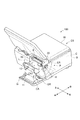
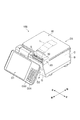
- FIG. 1 is an external perspective view of an electronic balance equipped with a label printer according to an embodiment.
- FIG. 2 is a perspective view of a state in which the label cassette is pulled out from the electronic balance.
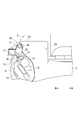
- FIG. 3 is a cross-sectional view of the main part of the printing unit of the label printer.
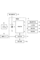
- FIG. 4 is a block diagram of a schematic configuration of an electronic balance equipped with a label printer.
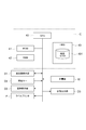
- FIG. 5 is a functional block diagram of the label printer.
- FIG. 6 is an example of product information registered in the product master.
- FIG. 7 is an example of an operation screen for issuing a fixed amount label.
- FIG. 8 is an example of the operation screen in a state where the issue of the fixed amount label is switched to the next product.
- FIG. 9 is an example of an operation screen on which a reservation list is displayed.
- FIG. 10 is an external perspective view of an electronic scale equipped with a modified label printer.
- 11A and 11B show a schematic configuration of the moving mechanism included in the label printer of FIG. 10, and FIG. 11A shows a case where the free roller is located at the first position.
- FIG. 11B is a diagram illustrating a case where the second position is located.
- FIG. 12 is a diagram showing a schematic configuration of a moving mechanism included in the label printer of FIG.
- FIGS. 1 to 3 the side on which the store clerk display unit D1 is disposed is “front” and the side on which the store clerk display unit D1 is disposed. Will be described as “rear”, the left side when viewing the electronic balance 100 from the front is “left”, and the right side when viewing the electronic balance 1 from the front is described as “right”. It is not intended to limit.
- an electronic balance 100 with a printer includes a main body case B, a label printer P incorporated therein, a weighing unit W installed on the upper surface of the main body case B, and a main body case.
- a control unit C controls the label printer P and the weighing unit W, and a power supply unit (not shown) that is also installed in the main body case B and supplies power to the label printer P and the control unit C.
- the electronic balance 100 with a printer is provided with a touch panel type clerk side display unit D1 and a fixed key D2 on the front side of the main body case B operated by the clerk, and a customer side display unit D3 on the back side. Yes.
- the label printer P is stored on the right side in the main body case B.
- the open / close door G is provided in front of the main body case B. If the case of the clerk-side display unit D1 provided in front of the opening / closing door G is flipped upward, the opening / closing door G can be opened downward as shown in FIG. If the open / close door G is opened, the cassette CA can be taken out. A handle is attached to the front portion of the cassette CA, and the cassette CA can be pulled out from the main body case B by pulling it forward.
- the label printer P includes a cassette CA for storing the label roll LR, a platen roller 12 provided at the upper end of the cassette CA, a print head 11 provided on the back surface of the opening / closing door G, and an upper front end of the main body case B.
- the provided cutter unit 20 and a temporary attachment part 30 provided in the vicinity thereof are provided.
- a roll support portion R is supported in a cantilevered state on the left side wall CA1 of the cassette CA.
- the label roll LR in which the strip-like mountless label LB is wound around the paper tube is mounted on the roll support R.
- the mountless label LB pulled out from the label roll LR goes under the guide roller GR and is delivered to the platen roller 12 at the upper end of the leading end.
- the guide roller GR is attached to the side wall CA1 of the cassette CA in a cantilever state.
- the mountless label LB an adhesive is laminated on the back side of the paper as a base material, a heat sensitive agent that develops color by heat is laminated on the surface of the base material, and a silicone resin as a release agent is applied on the heat sensitive material. ing.
- the label roll LR is wound around a paper tube with the back surface of such a mountless label LB inside, and is attached to the roll support R so that the back surface of the label roll LR contacts the platen roller 12.
- an identification code for identifying whether the mounted label roll LR is a label with a mount or a mountless label LB is attached to the rear portion of the cassette CA.
- the identification code is read by the reading unit.
- the reading unit notifies the control unit C of the identification code, that is, the type of the attached label roll LR.
- the print head 11 provided on the back surface of the open / close door G is a thermal print head.
- the heat generation line of the print head 11 contacts the platen roller 12 of the accommodated cassette CA. So that it is positioned.
- FIG. 3 is a cross-sectional view of the main part of the printing unit 10 having the print head 11 and the platen roller 12.
- the support frame 13 is attached to the back surface of the open / close door G so as to approach and separate from the open / close door G via a hinge (not shown).
- the print head 11 is fixed inside the support frame 13.
- a spring 14 is provided between the support frame 13 and the open / close door G to press the print head 11 against the platen roller 12 when the open / close door G is closed.
- a platen roller 12 is attached to the upper end of the cassette CA.
- a first guide plate 15 for restricting the movement path of the printed print label L (mountingless label LB) is disposed.
- the first guide plate 15 is disposed on the downstream side of the platen roller 12 in the feeding direction of the print label L (mounting-less label LB).
- a gear mechanism for driving the platen roller 12 is incorporated in the side wall CA1 of the cassette CA.
- a second guide plate 16 that restricts the movement path of the print label L is disposed at the tip of the support frame 13 on the door G side.
- the first guide plate 15 and the second guide plate 16 face each other so that the print label L (mountless label LB) is gradually narrowed in the direction in which the print label L (mounting-less label LB) is sent out. It is arrange
- the print label L (mounting-less label LB) is sent out from one end portion where the gap between the first guide plate 15 and the second guide plate 16 becomes narrow.
- a cutter unit (cutter) 20 having a fixed blade 21 and a movable blade 22 is mounted on the main body case B above the guide plates 15 and 16 and the platen roller 12.
- the cutter unit 20 is configured such that the movable blade 22 is connected to a crank mechanism inside the cutter unit 20 and reciprocates at a high speed in the horizontal direction with the fixed blade 21.
- the space between the fixed blade 21 and the movable blade 22 is arranged so as to face up and down with respect to the gap formed by the pair of guide plates 15 and 16.
- a temporary attachment portion 30 is disposed above the space between the fixed blade 21 and the movable blade 22.
- the temporary attachment part 30 has a free roller 32 and a pressing member 31 that lightly presses the print label L on the surface thereof.
- a rotatable roller having an uneven surface is used.
- the pressing member 31 is formed of a thin resin plate and lightly presses the printed label L that has been issued to the free roller 32.
- the interval between the temporary attachment portion 30 and the fixed blade 21 is set to a distance that can sufficiently hold the tip portion of the printed label L that has been issued.
- the free roller 32 and the pressing member 31 are fixed to the cover case 23 that covers the cutter unit 20. However, the temporary attachment portion 30 can be unitized and moved away from the fixed blade 21. You may do it.
- the weighing unit W has a well-known load cell that converts mechanical strain into an electric signal, a signal processing circuit that amplifies the electric signal output from the load cell and converts it into a digital signal, and controls the digital signal in the body case B A communication module that wirelessly transmits to the part C, and a battery unit that supplies power to the communication module. Also, in the main body case B, a communication module that receives the digital signal transmitted from the weighing unit W, the received digital signal is converted into mass, and the mass is multiplied by the unit price per unit mass set. And a control unit C that displays the calculated price on the clerk-side display unit D1 and the customer-side display unit D3, a label printer P, and a power supply unit that supplies power to them are housed. In this embodiment, the weight signal is wirelessly transmitted from the weighing unit W to the control unit C, but may be transmitted by wire instead.
- the clerk side display unit D1 is a touch panel type liquid crystal display, and a necessary operation screen is displayed under the control of the control unit C.
- the fixed key D2 includes a unit price key, a fixed amount key, a tare key, and a call key D21 for use with a key, and a print key D22 for instructing the issuance of a print label L, which are arranged together with a numeric key.
- the customer side display unit D3 (see FIG. 4) is a liquid crystal display, and displays an advertisement message about the product in addition to the weight and price.
- FIG. 4 shows a block diagram of the configuration of the electronic balance 100 with a printer
- FIG. 5 shows a functional block diagram executed by the label printer P.
- the control unit C includes a CPU 40, a ROM 41, a RAM 42, and an HDD (Hard Disc Drive) 43.
- the control unit C is electrically connected to the weighing unit W, the clerk side display unit D1, the fixed key D2, the customer side display unit D3, and the label printer P.
- the ROM 41 stores a control program for the electronic scale and the label printer P, and the CPU 40 reads and executes the control program, thereby realizing various functions as a label printer P described later in addition to the function as a scale. Is done.
- the RAM 42 stores, for example, reservation registration data for printing label L issuance, a log file for the issued printing label L, printing information to be output to the label printer P, and the like.
- the HDD 43 stores a product master 431 shown in FIG.
- the product designation means 5 When using as a crisp, operate the product designation means 5 (see FIG. 5) displayed on the clerk side display unit D1. Alternatively, the product number is input with the numeric keys in FIG. 1, and then the call key D21 is operated. And if the said goods are mounted in the measurement part W, the weight, price, and goods name of the said goods will be displayed on the salesclerk side display part D1 and the customer side display part D3.
- the platen roller 12 rotates in the reverse direction, and the leading edge of the mountless label LB is returned to the heat generation line of the print head 11 while the mountless label LB sent to the cutting position is retracted. Subsequently, the platen roller 12 rotates in the forward direction, and the weight, price, product information, etc. are printed in a predetermined format while feeding the mountless label LB. In the meantime, the fed mountless label LB passes between the pair of guide plates 15 and 16 and further rises through between the fixed blade 21 and the movable blade 22. And even if printing is completed, the platen roller 12 further rotates until the trailing edge of the mountless label LB as the print label L reaches the cutting position. As a result, the leading end portion of the mountless label LB enters between the pressing member 31 and the free roller 32, so that the leading end portion of the mountless label LB is pushed by the pressing member 31 and tilted toward the measuring unit W.
- the cutter unit 20 When the feeding by the platen roller 12 is stopped, the cutter unit 20 immediately operates and the movable blade 22 cuts the boundary line of the front and rear print labels L. Then, since the rear end portion of the print label L is pushed by the movable blade 22 and the front end portion of the print label L is inclined toward the measuring portion W, the rear end portion of the print label L is in the opposite direction. That is, it moves toward the clerk side display unit D1 and stops. As a result, the adhesive surface of the cut print label L moves to a position that does not hinder the progress of the leading end of the subsequent mountless label LB. In this way, when the printed label L of the weighed product is issued, the operator takes the printed label L stopped at the temporary attachment portion 30 and attaches it to the product.
- the operation of each unit described above is realized by the CPU 40 of the control unit C reading out the control program from the ROM 41 and executing it.
- FIG. 5 shows functional blocks realized by the control unit C executing a control program when, for example, a print label L such as a flat-rate label is continuously issued by the label printer P.
- the product designating means 5 shown in FIG. 5 is a means for designating a product for which the printed label L is issued.
- product names such as “Domestic beef slices” and “young chicken fillet” It is configured as a section display column in which is displayed. If any of the partition display fields is touched, the touched partition display field is detected and a product in the partition display field is designated. Further, instead of this method, the product can be designated by inputting the product number using the numeric keys shown in FIG. 1 and then operating the call key D21. Therefore, the product designation means 5 includes a numeric key and a call key D21. Note that the product number is registered in the product master 431 shown in FIG. 6, and corresponding product information is read from the product master 431 by inputting this number.
- the input means 6 is a means for inputting the number of print labels L to be issued for the designated product, for example, a numeric key shown in FIG.
- FIG. 7 shows an example of the operation screen displayed on the clerk side display unit D1.
- To issue a set number of print labels L using this screen for example, touch “Kobe beef fillet steak” as the product designation means 5, and then enter “10”, for example, with the numeric keys as the number of issues. To do.
- the control part C registers the number of issued sheets of “10” for the designated “Kobe beef fillet steak”.
- the head print label L is first issued in the same manner as described above, and then the mountless label LB separated from the head print label L is After the platen roller 12 is rotated in the reverse direction, the platen roller 12 is pulled back to the printing position, and then printed while being sent out again by the forward rotation.
- the boundary position between the preceding print label L and the subsequent print label L reaches the cutting position, the feeding of the mountless label LB is stopped at that time, and then the cutter unit 20 is operated and cut as the print label L.
- the mountless label LB is once pulled back and then sent out and printed.
- the initially set number of prints “10” is counted down, and the value is sequentially displayed in the number-of-issues display column 50.
- the cut print label L is held in the temporary attachment portion 30 in a forward leaning posture as shown in FIG. 3, but the mountless label LB to be the next subsequent print label L is subsequently sent out.
- the tip of the mountless label LB touches the adhesive surface of the preceding print label L
- the mountless label LB and the print label L are joined at that time.
- the mountless label LB is further sent out, the preceding print label L passes along the temporary attachment portion 30 and droops to the measuring portion W side. If it hangs down to the weighing section W side, the rear end of the print label L held by the temporary attachment section 30 will be inclined more and more toward the customer side display section D3. It will be something.
- the print labels L cut one by one are successively stacked on the rear end of the preceding print label L, and are continuously issued in a continuous form.
- the CPU 40 of the control unit C reading and executing the control program as described above.
- the next product is designated by the product designation means 5
- the number of print labels L to be issued is subsequently entered by the input means 6 (numeric keys), and the print key D22 is further operated.
- the section display column for the designated product is highlighted.
- the highlight in the section display column disappears and the background color of the reservation number display column 52 changes, and the reservation number is displayed in the reservation number display column 52 (see FIG. 8).
- the screen shown in FIG. 7 “young chicken fillet” is highlighted as the second designated product, and the initial number “10” of print labels L issued is reduced to “6”. , “Young chicken fillet” is selected as the next product.
- the registration means 7 can be used even when the print label L is being issued.
- the registered product and the number of issued cards are registered on the RAM 42 in the reserved order.
- the printing label L of “Kobe beef fillet steak” which is set first is finished, and the next reserved product “young chicken fillet” is read and printed label.
- a state where L is issued is shown.
- reservation registration is performed one after another by the above-described operation, and a total of five reservation registrations are performed. It shows that it is “Sasami”.
- a display field (display means 8) as shown in FIG. 9 appears and a reservation list is displayed.
- the display means 8 for displaying the reservation list may be displayed.
- the processed product list that has already issued the print label L and the unprocessed product list may be displayed in different colors on the display means 8.
- the changing means 9 shown in FIG. 5 is a means for changing the printing order of the print labels L of the reserved products. For example, as shown in FIG. Touch “Rose slice”, then enter “2” with the numeric keys, then touch “Change” key 53, “Pig rose slice” will move down to the second, and the second “Domestic slice of domestic beef peach” Is moved up first.
- a “removal” key 54 is operated after designating a reserved product in the reservation list, the reservation of the designated product is canceled.
- the issuance order is changed, the reserved product is deleted, or a new product is reserved and registered.
- the product can be interrupted in the higher order of the issue order, and the inconsistency between the work order and the issue order of the print labels L can be resolved.
- a notification label that prints a blank label or a mark is registered in the registration means 7, and when the reservation issuance of the label is completed and the print information of the next reserved product is read, the notification label is issued. Then, it is connected to the rear end portion of the preceding print label L, and then the print information of the next reserved product is read and the print label L of the next product is issued.
- the registration means 7 reads the information related to the information label that prints the blank label or the mark, and issues the information label before reading the print information of the next reserved product after the issuance of the print number of the reserved number is completed.
- the printer is configured to connect to the rear end portion of the preceding print label L, and subsequently read the print information of the next reserved product and issue the print label L of the next product.
- the notification label can be interposed between the print label L of the preceding group and the print label L of the succeeding group, the operator identifies the boundary between the preceding group and the succeeding group, and The print label L can be removed from the label issuing port.
- the label issuing port of the label printer P is provided with a peeling sensor (detection sensor) S for detecting the issued print label L as shown in FIGS.
- the peeling sensor S detects the print label L at the label issuing port and outputs a detection signal to the safety means 71.
- the safety means 71 counts the number of prints each time the print label L is issued. If the print label L is still present at the label issuing port after the count value reaches a predetermined number, the safety means 71 next The stop of the printing label L issuance is notified. At the same time, the safety means 71 activates the warning means 710 to notify the operator of the stoppage of the printing label L by sound and / or light. As a result, a problem that the print label L sticks to the weighing pan by being issued in a state where the print label L is continuous for a long time is avoided.
- the safety means 71 Since the length of one print label L to be issued varies depending on the product depending on the print amount, the safety means 71 counts a pulse for rotating the platen roller 12 for the length of one print label L. You may monitor by doing. That is, when the count value described above reaches the length corresponding to the length of one print label L, the safety means 71 counts the number of sheets issued and issues the print label L. When the number of sheets exceeds a preset value, the printing label L is temporarily stopped. When the peeling sensor S detects that the print label L at the label issuing port has run out, the safety means 71 clears the number of print labels L at the label issuing port, which is the count value, and then prints to the registration means 7. An instruction to resume issuance of label L is given. Of course, the operation control of the safety means 71 is realized by the CPU 40 of the control unit C reading and executing the control program, as described above.
- the number of print labels L to be issued is counted.
- the label issuance is performed by counting drive pulses for rotating the platen roller 12 while taking forward and reverse feeds into account. It is also possible to calculate the length of the print label L sent to the mouth. In this case, since the feed length of the region where the front and rear print labels L partially overlap is constant, by subtracting the length of the overlap allowance from the length of the print labels L for the number of prints, The length of the print label L sent to the label issuing port can be obtained.
- the detection function of the peeling sensor S can be switched ON or OFF by operating the “Break” key 55 displayed in the vertical column at the right end shown in FIGS.
- the peeling sensor S is disposed at a position facing the print label L of the label issuing port, when using a label with a mount, it is determined whether or not the print label L that has been printed is peeled off from the mount. It becomes a sensor to detect.
- the information printed on the print label L includes basic information such as a product name and price, and additional information such as raw materials, seasonings, additives, and nutrients used in the product. These pieces of information are printed on a single print label L if the amount of print data printed on the print label L is small, but if the amount of print data is large, the product name label (basic information printed) There are cases where printing is performed separately on a printed label) and an attached label printed with additional information (printed label). Therefore, the control unit C does not separate the product name label including the product name label of the reserved product and the attached label such as an additive label of the product separately, and the product name label and the attached label.
- a switching means 72 is provided for switching to a single sheet issue mode in which the print labels L are combined and issued. The switching means 72 is also realized by executing a control program.
- the product name label and the attached label are alternately connected and the print label L is issued first. There may be a case where the product name label is issued for the reserved number, and then the attached label is issued for the reserved number.
- the second switching means 73 selects whether to issue the same label all together or different labels in order, that is, to issue the attached label alternately after the product name label.
- the second switching means 73 is displayed on the clerk-side display unit D1, and by operating it, it is possible to select whether or not to “batch issue”.
- the label format includes a format for the product name label and a format for the attached label, There is an address store name field. Therefore, when these formats are connected and combined into a single label and issued, the address store name field of the product name label is deleted, and the first print field of the attached label is filled in that field. . Thereby, the label length to be issued can be set to the minimum necessary length.
- the print label L is divided into two sheets.
- the print label L may be divided into three or more sheets.
- the switching means 72 issues the print label L as one sheet or divides it into two sheets according to the amount of print data for printing the print label L of each product. It is configured so that it can be issued, or can be issued in three.
- print data includes product information such as product name and price, as well as additives and recipes
- the switching means 72 is divided into product name labels, additive labels, and recipe labels. Issue. In this case, when “collective issue” is selected by the second switching means 73, after the product name label is issued for the reserved number, the additive label is issued for the reserved number, and then the recipe label is set for the reserved number. Will be issued.
- the position of the free roller (temporary attachment portion) 32 with respect to the platen roller (printing portion) 12, the feeding direction of the printing label L, and the printing label You may further provide the moving mechanism 60 which can be switched to the direction (right-and-left direction shown to Fig.11 (a) and FIG.11 (b)) substantially orthogonal to the direction orthogonal to the L printing surface.
- the moving mechanism 60 includes an extruding portion 61 and a solenoid 63.
- the free roller 32 As shown in FIGS. 11A and 11B, the free roller 32 has a shaft portion 32A, a roller portion 32B, and a spring 32C.
- the roller portion 32B is rotatably provided with respect to the shaft portion 32A. Both ends of the shaft portion 32 ⁇ / b> A are supported by a cover case 23 that covers the cutter unit 20.
- a spring 32C that urges the free roller 32 in a direction away from the support portion 32D is disposed between one support portion 32D and the roller portion 32B among the support portions of the cover case 23 and the shaft portion 32A. .
- the peripheral surface thereof is formed in an uneven shape.
- the pressing member 31 and the free roller 32 are fixed to the cover case 23 that covers the cutter unit 20.
- the temporary attachment portion 30 can be unitized so as to be close to and away from the cutter unit 20. It may be.
- the pushing portion 61 has a contact portion 61A, a shaft portion 61B, and a spring 61C.
- the contact portion 61A is in contact with the other end portion of the shaft portion 32A.
- One end portion of the shaft portion 61B is connected to the contact portion 61A, and the other end portion is connected to the solenoid 63 via the support portion 61D.
- a spring 61C that urges the contact portion 61A away from the support portion 61D is disposed between the contact portion 61A and the support portion 61D.
- the solenoid 63 is a drive part of the extrusion part 61.
- the solenoid 63 linearly drives the shaft portion 61B by energizing the coil 63A included in the solenoid 63. Specifically, the solenoid 63 is driven in the vertical direction shown in FIGS. 11A and 11B, and when the coil 63A is energized, the shaft portion 61B is moved downward.
- the temporary attachment portion 30 is configured so that the first direction (the left-right direction shown in FIG. 11A) is perpendicular to the feeding direction of the print label L and the direction perpendicular to the print surface of the print label L. ) To the first position P1 and the second position P2.
- Control unit C controls the moving mechanism 60 to switch the position of the free roller 32.
- the control unit C of the present embodiment may switch the position of the free roller 32 when the printing label L of the number reserved by the registration unit 7 has been issued. That is, every time printing of the number of print labels L reserved by the registration means 7 is completed, the position of the free roller 32 is changed to the first position P1 (see FIG. 11A) and the second position P2 (FIG. 11A). ))) Alternately.
- Such control is performed, for example, by loading a program stored in the ROM onto the RAM and executing it by the CPU.
- the group when printing of the print label L of the preceding group is completed, the group is switched by shifting the free roller 32 holding the print label L to the left and right by a predetermined amount with respect to the platen roller 12. It is possible to shift the print labels L of the corresponding portions. As a result, the operator can identify the boundary between the preceding group and the succeeding group, and can therefore remove the printed label L that has been issued for each group.
- the label printer P may have a moving mechanism 160 having the following configuration.
- the free roller 32 in the temporary attachment portion 30 may be configured to be movable in multiple stages instead of the two stages of the first position P1 and the second position P2.
- the configuration of the moving mechanism 160 in this case will be described with reference to FIG.
- the moving mechanism 160 is common to the moving mechanism 60 in that the position of the free roller 32 relative to the platen roller 12 is moved in the left-right direction. As shown in FIG. 11, the moving mechanism 160 includes an extruding unit 161, a rack unit 163, a pinion unit 165, a motor 167, and a position acquisition unit 169. Note that the configuration of the free roller 32 is the same as that of the above embodiment, and thus the description thereof is omitted here.
- the extruding part 161 is in contact with the other end of the shaft part 32A.
- the contact surface 161A that comes into contact with the shaft portion 32A in the pushing portion 161 is inclined downward to the left, and pushes the shaft portion 32A to the left following the upward movement of the pushing portion 161.
- the rack part 163 is movably supported by the support part 170.
- the rack portion 163 is a rod-like member having one end connected to the extrusion portion 161 and can move integrally with the extrusion portion 161.
- the rack portion 163 is formed with teeth 163A that mesh with the teeth of the pinion portion 165 that is rotationally driven by the motor 167.
- An example of the motor 167 is a stepping motor.
- the rack part 163 and the pinion part 165 constitute a rack and pinion, and the rotational force in the motor 167 is converted into the vertical movement of the pushing part 161.
- the position acquisition unit 169 includes a detection plate 169A provided in the rack unit 163 and a sensor 169B provided in the fixed unit. A plurality of the sensors 169B may be arranged along the moving direction of the rack portion 163. The position acquisition unit 169 acquires the position in the vertical direction of the pushing unit 161 with respect to the support unit 170 when the sensor 169B detects the detection plate 169A.
- the pushing portion 161 is also moved downward.
- the shaft portion 32A of the free roller 32 that comes into contact with the pushing portion 161 moves to the right along the contact surface 161A by the biasing force of the spring 32C. That is, the free roller 32 moves relatively to the right side.
- the pushing part 161 is also moved upward.
- the shaft portion 32A of the free roller 32 that contacts the pushing portion 161 is pushed leftward along the contact surface 161A. That is, the free roller 32 moves relatively to the left.
- the position acquisition unit 169 can acquire the position of the rack unit 163 in the vertical direction, the position of the free roller 32 that moves in the horizontal direction in conjunction with this can also be acquired.
- the free roller 32 is perpendicular to the horizontal direction shown in FIG. 12 (the feeding direction of the print label L and the direction perpendicular to the print surface of the print label L (mounting-less label LB)). It is possible to move in multiple stages in one direction.
- the free roller 32 to which the print label L is attached every time the print label L is issued is replaced with the platen roller 12.
- the sheets By shifting the sheet by a predetermined amount in the left-right direction, the sheets can be stacked while being shifted left and right one by one, and when the group is switched, the displacement direction and / or displacement amount of the print label L can be relatively increased.
- the operator can identify the boundary between the preceding group and the succeeding group, and can therefore remove the printed label L that has been issued for each group.
- the print label L is sent upward, but it may be sent downward.
- the issued print label L hangs down to the front side where the operator is located. Therefore, when the electronic balance 100 with a printer is installed on the table, the issued print label is measured. Touching the part W can be prevented.
- the print head 11 and the platen roller 12 are arranged upside down and the label roll LR is mounted in the reverse direction so that the print surface is on the top and the adhesive surface is on the bottom.
- the mountless label LB may be sent out.
- the feed length for one print label L can be grasped in advance from these pieces of information. Therefore, the feed length of the print label L is registered for each product in the product master 431 shown in FIG. 6, and the print label L of the label issuing port is determined based on the registered feed length of the print label L. The number and / or length is calculated. In addition, the number of print labels L that are issued to the label issuing port, or how long the label L is attached, is obtained in advance as to how it will stick to the periphery, and the number and length of each label are registered for each product. May be.
- the number and / or length of the print label L allowed at the label issuing port is also different. Therefore, when the type of the reserved registered product is switched, the already issued print Until the label L is removed from the label issuing port, the printing label L to be attached to the next product may be stopped. This not only eliminates the presence of print labels L having different print contents at the label issuing port, but also facilitates the calculation of the number and / or length of the print labels L to be retained at the label issuing port.
Landscapes
- Labeling Devices (AREA)
- Printers Characterized By Their Purpose (AREA)
Abstract
ラベルプリンタは、予約された商品に関する情報が印字された印字ラベルを、予約された枚数分順次発行するラベルプリンタであって、商品を指定する指定手段と、指定手段によって指定された商品に関する情報が印字された印字ラベルの発行枚数を入力する入力手段と、印字ラベルの発行中に、指定手段による商品の指定と入力手段による印字ラベルの発行枚数の入力とを受け付けて予約登録する登録手段と、を備える。
Description
本発明は、ラベルプリンタに関する。
スーパーマーケット等において、惣菜又は弁当等に一定金額の定額ラベルを貼り付ける場合、店員等は、ラベルプリンタを用いて複数枚の定額ラベルを一度に発行し、盛り付け台に並べられた弁当等に一枚ずつ貼り付けている。
こうした定額ラベルを発行するラベルプリンタが、下記特許文献1に記載されている。このラベルプリンタは、台紙付きラベルを使用するものであり、複数商品の印字内容と発行枚数を予約して、予約された各商品の印字ラベルを予約枚数ずつ連続して発行することができる。店員等が貼り付け作業をする際には、このラベルプリンタを用いて、予約された各商品の定額ラベルを予約枚数ずつ連続発行させる。
このようなラベルプリンタでは、次に処理される商品が出来上がるタイミングと、その商品に貼り付ける印字ラベルの発行タイミングとをマッチさせたいという要望がある。
そこで、本発明は、次に処理される商品が出来上がるタイミングと、その商品に貼り付ける印字ラベルの発行タイミングとをマッチさせることができるラベルプリンタを提供することを目的とする。
本発明の一側面に係るラベルプリンタは、予約された商品に関する情報が印字された印字ラベルを、予約された枚数分順次発行するラベルプリンタであって、商品を指定する指定手段と、指定手段によって指定された商品に関する情報が印字された印字ラベルの発行枚数を入力する入力手段と、印字ラベルの発行中に、指定手段による商品の指定と入力手段による印字ラベルの発行枚数の入力とを受け付けて予約登録する登録手段と、を備える。
これにより、印字ラベルの発行中においても、次に処理される商品の印字ラベルの発行予約ができるので、次に処理される商品が出来上がるタイミングと、その商品に貼り付ける印字ラベルの発行タイミングとをマッチさせることができる。したがって、発行された一連の定額ラベルをラベルプリンタから取り去った後、それを直ちに商品に貼り付けることができる。
一実施形態において、ラベルプリンタは、登録手段によって予約登録された予約内容を一覧表示する表示手段を更に備えてもよい。ところで、盛り付け台に並べられた弁当等の商品に定額ラベルを順次貼り付けていく作業では、商品の種類とそれに貼付するラベルとの不一致は避けねばならない。このため、複数商品のラベル発行予約をするときは、作業順序と、予約ラベルの発行順序とを一致させておく必要がある。ここで、作業順序とは、例えば、最初に幕の内弁当を10個作り、続いて日替わり弁当を20個作るという順序である。この順序が入れ替わったり、他の商品が割り込んだりすると、既に発行された定額ラベルを一時退避させておく必要がある。一実施形態のラベルプリンタでは、予約された商品の印字ラベルの発行順序を確認することができるから、作業順序とラベル発行順序とが一致しているか否かを確認することができる。これにより、予約順序のミスを未然に防止することができる。
一実施形態において、ラベルプリンタは、登録手段によって予約された商品の印字ラベルの発行順序を変更する変更手段を更に備えてもよい。ところで、複数商品のラベル発行予約を行った場合に、作業順序が急に入れ替わったり、追加の商品が割り込まれたりすると、予約発行されたラベルシートの取り扱いに困るという問題がある。一実施形態のラベルプリンタでは、作業順序とラベル発行順序との間に不整合が生じても、発行順序を入れ替えたり、予約商品を消去したり、新たな商品を発行順序の上位に割り込ませたりすることにより、上記不整合を解消することができる。
一実施形態において、ラベルプリンタは、ロール状に巻かれた台紙レスラベルを送り出しながら当該台紙レスラベルに印字する印字部と、印字部の下流側に配置されて、印字された台紙レスラベルを所定長さで切断するカッターと、カッターによって切断された印字ラベルを表裏から保持するとともに、切断された印字ラベルの後端部と、切断された印字ラベルの次に送り出される後続印字ラベルの先端部と、を重ね合わせる仮着部と、を更に備えていてもよい。
また、一実施形態において、ラベルプリンタは、ロール状に巻かれた台紙レスラベルを送り出しながら当該台紙レスラベルに印字する印字部と、印字部の下流側に配置されて、印字された台紙レスラベルを所定長さで切断するカッターと、カッターによって切断された印字ラベルを表裏から保持するとともに、切断された印字ラベルの送り出し方向における上流側の後端部と、切断された印字ラベルの次に送り出される後続印字ラベルの送り出し方向における下流側の先端部と、を重ね合わせる仮着部と、を備えていてもよい。
最近使われるようになった、ラベルの粘着面に台紙(剥離紙)が貼付されていない、所謂、台紙レスラベルでは、印字ラベルを印字する度に、当該印字ラベルがラベルロールから切断される。このような台紙レスラベルでは、これまでの台紙付きラベルのように、シート状に連なった状態で印字ラベルを発行させることはできない。この構成のラベルプリンタでは、切断された印字ラベルの後端部と、切断された印字ラベルの次に送り出される後続印字ラベルの先端部と、が重ね合わされて、複数の印字ラベルが連なったシート状の印字ラベルを発行することができる。
この構成のラベルプリンタによれば、台紙レスラベルから印字ラベルを発行する都度、先行印字ラベルの後端部に後続印字ラベルの先端部を次々と貼り付けていくから、一枚ずつ発行された台紙レスラベルでありながら、シート状に連なった一連の印字ラベルを発行することができる。しかも、商品毎に印字量が変化しても、発行する印字ラベルの長さを変えて対応させることができるから、1枚の印字ラベルが一定寸法に規定された台紙付きラベルよりも、汎用性を向上させることができる。加えて、印字空白を最小限に抑えることができるから、一商品当たりのラベル使用量も減少させることができる。
また、従来の台紙付きラベルでは、発行されたラベルをそのまま放置しても、印字ラベルは台紙に貼り付いたままであるから、問題にはならなかった。しかし、台紙レスラベルでは、複数枚連ねた状態で発行された印字ラベルをラベルプリンタから取り去ると、粘着面が剥き出しのままになっているから、発行されたラベルシートの取り扱いを誤ると、印字ラベル同士がくっ付いたり、印字ラベルがラベル発行装置や、その周囲の物、壁、又は床に貼り付いたりして、印字ラベルが使用できなくなる問題がある。
この構成のラベルプリンタでは、発行された一連の定額ラベルをラベルプリンタから取り去った後、それを直ちに商品に貼り付けることができる。このため、粘着面が剥き出しの一連のラベルを放置するがなくなり、台紙レスラベルを使用する場合でも、発行されたラベルの損傷や取り扱いミスを無くすことができる。
なお、ここで使用するラベルは、好ましくは台紙レスラベルであるが、台紙付きラベルであっても良い。また、ラベルプリンタは、台紙付きラベル及び台紙レスラベルの何れも印字発行ができる兼用型が良いが、一方のラベルだけが印字発行できる専用型でも良い。
一実施形態において、ラベルプリンタは、登録手段によって予約された枚数の印字ラベルの発行が終了すると、印字部は、次に印字される印字ラベルとの境目を知らせる報知ラベルを印字してもよい。この報知ラベルは、例えば、空白のラベル、又は目印を印字したラベル等である。このラベルを、先行グループの印字ラベル発行後に発行させ、それを先行グループの印字ラベルの後端部に接続し、更に後続グループの印字ラベルをその報知ラベルの後端部に接続させる。これにより、作業者は、先行グループと後続グループとの境目を識別することができるから、発行された印字ラベルをグループ毎に纏めて取り去ることができる。また、作業者は、先行グループと後続グループとの境目を識別することができるので、先行グループの商品用ラベルと、後続グループの商品用ラベルとを同時に取り去るミスを防止することができる。
また、この報知ラベルに代えて、例えば、先行グループには、各印字ラベルの右側余白部分に小さなドットを印字し、後続グループには、各印字ラベルの左側余白部分に小さなドットを印字する方法もある。こうすれば、それらのドットの並びが左右入れ替わったところが、先行グループと後続グループの境目となるから、それによって区別することができる。
一実施形態において、ラベルプリンタは、印字部に対する仮着部の位置を、印字ラベルの送り出し方向と印字ラベルの印字面に直交する方向とに略直交する方向に切替可能にする切替機構を更に備え、切替機構は、登録手段によって予約された枚数の印字ラベルの発行が終了すると、仮着部の位置を切り替えてもよい。
この構成では、先行グループの印字ラベルの印字が終わった時点で、印字ラベルの仮着部を、印字部に対して所定量左右方向へずらすことにより、グループの切り替わった部分の印字ラベル同士をずらすことができる。また、グループとは関係なく、印字ラベルが発行されるごとに印字ラベルの仮着部を、印字部に対して所定量左右方向へずらすことにより、一枚ずつ左右にずらしながら積層し、グループが切り替わったところで印字ラベルのずれ方向及び/又はずれ量を相対的に大きくすることもできる。これにより、作業者は、先行グループと後続グループとの境目を識別することができるから、発行された印字ラベルをグループ毎に纏めて取り去ることができる。
一実施形態において、ラベルプリンタは、発行された印字ラベルの有無をラベル発行口において検出する検出センサと、印字ラベルが所定枚数発行された後に、検出センサにおいて印字ラベルが検出されると、次の印字ラベルの発行を停止する安全手段と、を更に備えてもよい。
ラベルプリンタに台紙レスラベルを使用する場合は、複数枚の台紙レスラベルがシート状に連なった状態で発行されるから、発行された印字ラベルが長くなる場合がある。印字ラベルが長くなり過ぎると、周囲、すなわちラベルプリンタの外面、ラベルプリンタの近傍に置かれた物、壁、又は床等に貼り付く虞がある。そこで、ラベルプリンタを使用する場合は、印字ラベルが所定枚数発行された後も、それがラベル発行口にある場合は、次の印字ラベルの発行を一時的に停止する。すなわち、連なった状態で発行される印字ラベルが周囲に貼り付く長さに達する前に、次の印字ラベル発行を停止するのである。これにより、印字ラベルが、ラベルプリンタの外面、ラベルプリンタの近傍に置かれた物、壁、又は床等に貼り付くことを抑制できる。
一実施形態において、ラベルプリンタは、登録手段によって予約された商品に関する情報を印字するための印字データ量に応じて、商品の印字ラベルを複数枚に分けて発行する複数枚発行モードと、商品の印字ラベルを複数枚に分けずに発行する発行モードとに切り替える切替手段を更に備えてもよい。
例えば、印字データには、商品名及び価格等の他に、その商品の原材料や添加物、更には、その商品の調理方法等が含まれる場合もある。そこで、切替手段は、商品に関する情報を印字するための印字データ量に応じて、例えば、品名及び価格等が含まれる品名ラベルと、その他のデータが含まれる付属ラベルとに分けて発行してもよい。また、後者の付属ラベルを更に添加物用ラベルとレシピ用ラベルとに分けて発行してもよい。そして、品名ラベルは、商品の表側に貼り付け、その他のラベルは、商品の裏面に貼り付けてもよい。これにより、一つの商品について、印字ラベルの1枚発行ができるだけでなく、上記印字データ量に応じて、ラベルの2枚発行又は3枚発行も行うことができる。
また、一つの商品に複数のラベル(品名ラベル及び付属ラベル等)を貼り付ける必要のある商品が複数個ある場合は、同じラベルをまとめて発行してから各商品に貼り付けていくか、複数のラベルを順番に発行しながら、各商品に貼り付けていくかを選択する第2切替手段を設けておいてもよい。例えば、前述のように、一つの商品に品名ラベル、添加物用ラベル、及びレシピ用ラベルを貼り付けていく場合に、それらを順番に発行しながら各商品に貼り付けて行くよりも、同じラベルをまとめて発行し、それを各商品に貼り付けてから、次のラベルを発行していく方が、作業性が良い場合がある。このような場合は、第2切替手段を操作してまとめ発行モードに設定する。そして、例えば、同じ商品が5つある場合は、最初に品名ラベルを5枚発行させ、発行された品名ラベルを各商品の表側に貼り付けていく。次に添加物ラベルを5枚発行させ、発行された添加物ラベルを各商品の裏面に貼り付けていく。このようにラベルを発行することで作業性が改善することがある。
一実施形態において、ラベルプリンタは、前後に連なった状態で発行される印字ラベルの発行枚数又は長さの上限の設定を受け付けるとともに、上限に達すると印字ラベルの発行を停止させる制御部を更に備えてもよい。
本発明の一側面に係るラベルプリンタは、ロール状に巻かれた台紙レスラベルを送り出しながら当該台紙レスラベルに印字する印字部と、印字部の下流側に配置されて、印字された台紙レスラベルを所定長さで切断するカッターと、カッターによって切断された印字ラベルを表裏から保持するとともに、切断された印字ラベルの後端部と、切断された印字ラベルの次に送り出される後続印字ラベルの先端部と、を重ね合わせる仮着部と、前後に連なった状態で発行される印字ラベルの発行枚数又は長さの上限の設定を受け付けるとともに、上限に達すると印字ラベルの発行を停止させる制御部と、を備える。
本発明の一側面に係るラベルプリンタは、ロール状に巻かれた台紙レスラベルを送り出しながら当該台紙レスラベルに印字する印字部と、印字部の下流側に配置されて、印字された台紙レスラベルを所定長さで切断するカッターと、カッターによって切断された印字ラベルを表裏から保持するとともに、切断された印字ラベルの送り出し方向における上流側の後端部と、切断された印字ラベルの次に送り出される後続印字ラベルの送り出し方向における下流側の先端部と、を重ね合わせる仮着部と、前後に連なった状態で発行される印字ラベルの発行枚数又は長さの上限の設定を受け付けるとともに、上限に達すると印字ラベルの発行を停止させる制御部と、を備える。
この構成では、印字ラベルが所定枚数発行された後も、それがラベル発行口にある場合は、次の印字ラベルの発行を一時的に停止する。すなわち、連なった状態で発行される印字ラベルが周囲に貼り付く長さに達する前に、次の印字ラベル発行を停止するのである。これにより、印字ラベルが、ラベルプリンタの外面、ラベルプリンタの近傍に置かれた物、壁、又は床等に貼り付くことを抑制できる。
ここで、印字ラベルが周囲に貼りつく長さは、印字ラベルを送り出す方向や、印字ラベル1枚分の長さ、印字ラベルの腰の強さ、更にはラベルプリンタが配置される周囲状況によって左右される。このため、使用する印字ラベルの種類、又は印字データ量に応じて、印字ラベルを何枚連ねて発行すると、或いはどの位の長さまで連ねると、周囲に貼り付くかを事前に把握しておくとよい。そして、周囲に貼り付かないぎりぎりの印字ラベル枚数又は長さを、所定枚数又は所定長さとして商品別に登録しておいてもよい。商品別に登録するのは、商品によって印字データ量が異なり、それによってラベルの送り長さが異なるからである。
一実施形態において、ラベルプリンタは、発行された印字ラベルの有無をラベル発行口において検出する検出センサを更に備え、制御部は、印字ラベルがラベル発行口において所定枚数又は所定長さに達した後に、検出センサにおいて印字ラベルが検出されると、次の印字ラベルの発行を停止させてもよい。
この構成によれば、発行された印字ラベルが所定枚数又は所定長さに達した後も、印字が検出センサによって検出される場合は、安全手段(又は制御部)は、次のラベル発行を停止するので、長く連なった状態で発行された印字ラベルが周囲に貼り付いたりする問題を未然に防止することができる。
一実施形態において、制御部は、ラベル発行口にある印字ラベルが所定枚数又は所定長さに達する前に取り除かれたことが検出センサによって検出された場合は、次の印字ラベルを続けて発行させてもよい。
一実施形態において、制御部は、印字ラベルを発行する都度、ラベル発行口にある印字ラベルの枚数又は長さを求めてもよい(算出してもよい)。
一実施形態において、制御部は、検出センサの検出信号に基づいて、ラベル発行口から印字ラベルが取り除かれたと判断すると、先に求めたラベル発行口にある当該印字ラベルの枚数又は長さをクリアしてもよい。このようにして、次の印字ラベル発行に備えてもよい。
こうした動作は、登録された予約枚数分のラベル発行が終了するまで続く。すなわち、印字ラベルがラベル発行口から除去されたことを検出センサが検出すると、印字ラベルの発行が自動的に再開される。したがって、作業者は、予約ラベルの発行操作を開始させた後は、ラベルプリンタを操作しなくても、連なった状態で発行される印字ラベルをラベル発行口から取り除いては、それを商品に貼り付けていくだけとなるから、作業性が極めてよくなる。この場合において、ラベル発行の一時停止を音や光で知らせる警告手段を設けておけば、発行されたラベルの除去を促すことができる。
一実施形態において、制御部は、次に発行する印字ラベルの印字内容が、直前に発行した印字ラベルの印字内容と異なるときは、ラベル発行口にある印字ラベルが取り除かれことが検出センサによって検出されなくなるまで、次に発行する印字ラベルの発行を停止してもよい。
この構成によれば、ラベル発行口において、印字内容の異なる印字ラベルの混在を無くすことができるので、異なる商品へ異なる印字ラベルが貼り付けられるミスを防止することができる。なお、この場合にも警告手段によって音及び/又は光を発するのが好ましいが、この場合の音及び/又は光は、前述の音及び/又は光とは異なる音色や波長としておくのが好ましい。
本発明によれば、次に処理される商品が出来上がるタイミングと、その商品に貼り付ける印字ラベルの発行タイミングとをマッチさせることができる。したがって、発行された一連の定額ラベルをラベルプリンタから取り去った後、それを直ちに商品に貼り付けることができる。
まず、図1~図4を参照しながら、本発明のラベルプリンタが搭載された電子秤の一実施形態を説明する。なお、以下の実施形態は、本発明の技術的範囲を限定するものではない。また、図面の寸法比率は、説明のものと必ずしも一致していない。なお、本明細書では、説明の便宜のために、図1~図3に示されるように、店員側表示部D1が配置された側を「前」、店員側表示部D1が配置された側と反対側を「後」、前から電子秤100を見て左となる側を「左」、前側から電子秤1を見て右となる側を「右」として説明するが、本発明の構成を限定するものではない。
図1~図4に示されるように、プリンタ付き電子秤100は、本体ケースBと、その中に組み込まれたラベルプリンタPと、本体ケースBの上面に設置された計量部Wと、本体ケースBに組み込まれ、ラベルプリンタPと計量部Wとを制御する制御部C(図4参照)と、同じく本体ケースB内に組み込まれ、ラベルプリンタP及び制御部Cに給電する、図示しない電源ユニットを備える。また、プリンタ付き電子秤100は、店員が操作する本体ケースBの正面側に、タッチパネル式の店員側表示部D1と固定キーD2とが設けられ、背面側に客側表示部D3が設けられている。
ラベルプリンタPは、本体ケースB内の右側に収納されている。開閉扉Gは、本体ケースBの正面に設けられている。開閉扉Gの前方に設けられた店員側表示部D1のケースを上方に跳ね上げれば、図2に示されるように、開閉扉Gを下方へ開くことができる。開閉扉Gを開けば、中からカセットCAが取り出せるようになっている。カセットCAの前部には、取手が取り付けられ、これを手前に引けば、カセットCAを本体ケースBから引き出すことができる。
ラベルプリンタPは、ラベルロールLRを収納するカセットCAと、カセットCAの先端上部に設けられたプラテンローラ12と、開閉扉Gの裏面に設けられた印字ヘッド11と、本体ケースBの前端上部に設けられたカッターユニット20と、その近傍に設けられた仮着部30とを備えている。また、カセットCAの左側の側壁CA1には、図2に示されるように、ロール支持部Rが片持ち状態で支持されている。紙管に帯状の台紙レスラベルLBが巻きつけられたラベルロールLRは、ロール支持部Rに装着される。ラベルロールLRから引き出された台紙レスラベルLBは、ガイドローラGRの下を潜って、先端上部のプラテンローラ12に引き渡される。ガイドローラGRは、カセットCAの側壁CA1に片持ち状態で取り付けられている。
台紙レスラベルLBは、基材である紙の裏面に接着剤が積層され、基材の表面に熱によって発色する感熱剤が積層され、当該感熱材の上から剥離剤としてのシリコン樹脂が塗布されている。ラベルロールLRは、このような台紙レスラベルLBの裏面を内側にして紙管に巻き付けられており、ラベルロールLRの裏面がプラテンローラ12と接触するようにロール支持部Rに装着される。
なお、カセットCAの後部には、装着されたラベルロールLRが台紙付きラベルか、台紙レスラベルLBかを識別する識別コードが付与されている。カセットCAを本体ケースB内に収納すると、読取部によってその識別コードが読み取られる。読取部は、当該識別コード、すなわち装着されたラベルロールLRの種類を制御部Cに通知する。
開閉扉Gの裏面に設けられた印字ヘッド11は、サーマル式の印字ヘッドで構成され、印字ヘッド11が有する発熱ラインは、開閉扉Gを閉じると、収納されたカセットCAのプラテンローラ12と接するように位置決めされている。
図3は、印字ヘッド11と、プラテンローラ12と、を有する印字部10の要部断面図を示す。この図において、開閉扉Gの裏面には、支持フレーム13が図示しないヒンジを介して開閉扉Gに近接離反するように取り付けられている。支持フレーム13の内側には、印字ヘッド11が固定されている。また、支持フレーム13と開閉扉Gとの間には、開閉扉Gを閉じたときに、印字ヘッド11をプラテンローラ12に押し付けるスプリング14が設けられている。
カセットCAの先端上部には、プラテンローラ12が取り付けられている。プラテンローラ12の上方には、印字された印字ラベルL(台紙レスラベルLB)の移動経路を規制する第1ガイド板15が配置されている。第1ガイド板15は、印字ラベルL(台紙レスラベルLB)の送り出し方向においてプラテンローラ12の下流側に配置されている。また、図2に示されるように、カセットCAの側壁CA1内には、プラテンローラ12を駆動するギア機構が組み込まれている。カセットCAを本体ケースBに装着すると、ギア機構が本体ケースB内の駆動モータと連結されてプラテンローラ12が回転する。
一方、開閉扉G側の支持フレーム13の先端部には、印字ラベルLの移動経路を規制する第2ガイド板16が配置されている。第1ガイド板15と第2ガイド板16とは、開閉扉Gを閉じた際に、印字ラベルL(台紙レスラベルLB)を送り出す方向に徐々に狭くなるように互いに対向(「ハ」の字に対向)するように配置されている。印字ラベルL(台紙レスラベルLB)は、第1ガイド板15と第2ガイド板16とが対向する隙間が狭くなる一方の先端部から送り出される。
ガイド板15、16及びプラテンローラ12の上方には、固定刃21と可動刃22とを備えたカッターユニット(カッター)20が、本体ケースB上に取り付けられている。カッターユニット20は、可動刃22がカッターユニット20内部のクランク機構に連結されて、固定刃21との間を水平方向に高速で往復運動するようになっている。
固定刃21と可動刃22との間のスペースは、一対のガイド板15、16によって形成されるギャップに対し上下に向き合うように配置されている。また、固定刃21と可動刃22との間のスペースの上方には、仮着部30が配置されている。
仮着部30は、フリーローラ32と、その表面に印字ラベルLを軽く押し付ける押さえ部材31と、を有している。フリーローラ32は、印字ラベルLの粘着面との接触面積を減らすために、その表面が凹凸状の回転自在なローラが用いられる。押さえ部材31は、薄い樹脂製プレートによって形成され、印字発行された印字ラベルLをフリーローラ32に軽く押さえる。また、仮着部30と固定刃21との間隔は、発行された印字ラベルLの先端部を十分保持することのできる距離に設定されている。本実施形態では、フリーローラ32と押さえ部材31とを、カッターユニット20を被うカバーケース23に固定しているが、この仮着部30をユニット化して、固定刃21に対して近接離反できるようにしても良い。
計量部Wは、機械的歪みを電気信号に変換する周知構成のロードセルと、ロードセルから出力される電気信号を増幅してデジタル信号に変換する信号処理回路と、デジタル信号を本体ケースB内の制御部Cに無線で送信する通信モジュールと、これらに給電するバッテリーユニットと、を備える。また、本体ケースB内には、計量部Wから送信されたデジタル信号を受信する通信モジュールと、受信したデジタル信号を質量に変換し、当該質量に設定された単位質量当りの単価を乗じて価格を算出し、算出した価格を店員側表示部D1と客側表示部D3とに表示する制御部Cと、ラベルプリンタP、ならびに、これらに給電する電源ユニットと、が収納されている。なお、この実施形態では、計量部Wから制御部Cに無線で重量信号を送信するように構成しているが、これに代えて有線で送信してもよい。
店員側表示部D1は、タッチパネル式の液晶ディスプレイであり、制御部Cの制御により、必要な操作画面が表示される。また、固定キーD2には、ハカリ用としての単価キー、定額キー、風袋キー、及び呼出キーD21と、印字ラベルLの発行を指示する印字キーD22と、があり、これらが数字キーと共に配置されている。また、客側表示部D3(図4参照)は、液晶ディスプレイであり、重量、価格の他、商品に関する広告メッセージが表示される。
図4は、プリンタ付き電子秤100の構成ブロック図を示し、図5は、ラベルプリンタPが実行する機能ブロック図を示す。図4において、制御部Cは、CPU40、ROM41、RAM42及びHDD(Hard Disc Drive)43を備える。制御部Cは、計量部W、店員側表示部D1、固定キーD2、客側表示部D3、及びラベルプリンタPと電気的に接続されている。
ROM41には、電子秤とラベルプリンタPの制御プログラムが記憶され、当該制御プログラムをCPU40が読み出して実行することにより、秤としての機能の他に、後述するラベルプリンタPとしての種々の機能が実現される。RAM42には、例えば、印字ラベルL発行の予約登録データ、発行された印字ラベルLのログ・ファイル、及びラベルプリンタPに出力する印字情報等が記憶されている。また、HDD43には、図6に示される商品マスタ431が記憶されている。
ハカリとして使用するときは、店員側表示部D1に表示される、商品指定手段5(図5参照)を操作する。あるいは、その商品番号を図1の数字キーで入力し、続いて呼出キーD21を操作する。そして、当該商品を計量部Wに載置すれば、当該商品の重量、価格、及び商品名が店員側表示部D1と客側表示部D3とに表示される。
続いて印字キーD22を操作すると、プラテンローラ12が逆回転して、切断位置まで送り出された台紙レスラベルLBを後退させながら台紙レスラベルLBの先端縁を印字ヘッド11の発熱ラインまで戻す。続いてプラテンローラ12が順方向に回転し、台紙レスラベルLBを送り出しながら重量、価格、及び商品情報等を所定のフォーマットで印字していく。その間、送り出された台紙レスラベルLBは、一対のガイド板15、16の間を通り、更に固定刃21と可動刃22との間を通って上昇していく。そして、印字が終了しても、プラテンローラ12は、更に印字ラベルLとしての台紙レスラベルLBの後端縁が切断位置に到達するまで回転する。これにより、台紙レスラベルLBの先端部分は、押さえ部材31とフリーローラ32との間に進入するから、台紙レスラベルLBの先端部分は、押さえ部材31に押されて計量部W側に傾く。
プラテンローラ12による送りが止まると、直ちにカッターユニット20が作動して可動刃22が前後の印字ラベルLの境界線上を切断する。すると、印字ラベルLの後端部分が可動刃22に押され、かつ、印字ラベルLの先端部分が計量部W側に傾いていることから、印字ラベルLの後端部分は、反対方向へ、すなわち、店員側表示部D1の方へ移動して止まる。これにより、切断された印字ラベルLの粘着面が後続の台紙レスラベルLBの先端部の進行を妨げない位置まで移動する。こうして、計量された商品の印字ラベルLが発行されれば、作業者は、仮着部30で止まった印字ラベルLを取ってそれを商品に貼り付ける。以上の各部の動作は、制御部CのCPU40がROM41から制御プログラムを読み出して実行することにより実現される。
図5は、例えば、定額ラベル等の印字ラベルLをラベルプリンタPによって連続発行させる場合に、制御部Cが制御プログラムを実行することによって実現される機能ブロックを示している。
図5に示される商品指定手段5は、印字ラベルLを発行させる商品を指定する手段であり、例えば図7に示されるように「国産牛モモ薄切り」及び「若鶏ムネ肉」等の商品名が表示された区画表示欄として構成されている。そして、何れかの区画表示欄がタッチされれば、タッチされた区画表示欄が検知されて区画表示欄の商品が指定される。また、この方法に代えて、図1に示される数字キーによって商品番号を入力し、続いて呼出キーD21を操作することによっても、商品を指定することができる。したがって、商品指定手段5には、数字キーと呼出キーD21とが含まれる。なお、商品番号は、図6に示される商品マスタ431に登録されており、この番号が入力されることにより、対応する商品情報が商品マスタ431から読み出される。
入力手段6は、指定された商品の印字ラベルLの発行枚数を入力する手段であり、例えば、図1に示される数字キーである。図7は、店員側表示部D1に表示された操作画面の一例を示す。この画面を使って設定枚数の印字ラベルLを発行させるには、例えば商品指定手段5としての「神戸牛ヒレステーキ」をタッチし、続いて、発行枚数として、例えば「10」を数字キーで入力する。これにより、制御部Cは、指定された「神戸牛ヒレステーキ」について「10」枚の発行枚数を登録する。なお、図7に示される商品指定手段5は、商品名が表示された複数の区画表示欄によって構成されるが、各表示欄に表示された「国産牛モモ薄切り」及び「若鶏ムネ肉」等の商品名は「精肉」キー、「鮮魚」キー、及び「惣菜」キーのタッチによって切り替わる。また、同一部門内で次の商品群を表示させるには、右下隅のページ切替キー51を押せばよい。これにより、「精肉」部門内の次の商品群が、区画表示欄として表示される。なお、「神戸牛ヒレステーキ」をタッチする代わりに、図6に示される商品マスタ431に登録された対応する商品番号、すなわち、「000001」を入力した後、図1に示される呼出キーD21を操作しても同様の画面が表示される。
続いて、図1に示される印字キーD22が押されると、前述と同様にして、まず先頭の印字ラベルLが発行され、続いて、先頭の印字ラベルLから切り離された台紙レスラベルLBは、プラテンローラ12の逆方向の回転により、印字位置まで引き戻された後、再び順方向回転によって送り出されながら印字されていく。そして、先行印字ラベルLと後続印字ラベルLとの境界位置が切断位置に到達すると、その時点で台紙レスラベルLBの送り出しが停止され、続いてカッターユニット20が作動して印字ラベルLとして切断される。こうして、台紙レスラベルLBは、一旦引き戻された後、送り出されて印字されていく。なお、印字ラベルLが1枚発行される度に、当初設定された発行枚数「10」がカウントダウンされ、その値が発行数表示欄50に逐次表示される。
一方、切断された印字ラベルLは、図3に示されるような前傾姿勢で仮着部30に保持されるが、続いて次の後続の印字ラベルLとなる台紙レスラベルLBが送り出されるから、台紙レスラベルLBの先端が先行印字ラベルLの粘着面に触れると、その時点で台紙レスラベルLBと印字ラベルLとは接合される。そして、更に続けて台紙レスラベルLBが送り出されると、それに伴って先行印字ラベルLは、仮着部30を通過して計量部W側へ垂れていく。計量部W側に垂れると、仮着部30に保持された印字ラベルLの後端部は、ますます客側表示部D3側へ傾斜することになるから、台紙レスラベルLBとの接合が確実なものとなる。こうした動作を繰り返して、一枚ずつに切断された印字ラベルLは、先行印字ラベルLの後端部に次々と重ね貼りにされて、シート状に連なった状態で連続発行される。勿論、こうした動作は、前述と同様に、制御部CのCPU40が制御プログラムを読み出して実行することにより実現される。
一方、最初の印字ラベルLの発行操作の直後に、あるいは、それに続く印字ラベルLの発行中に、次の商品の印字ラベルLの発行予約を行うことができる。具体的には、前述と同様、商品指定手段5によって次の商品を指定し、続いて入力手段6(数字キー)によって印字ラベルLの発行枚数を入力し、更に印字キーD22を操作する。例えば図7に示されるように、次の商品として「若鶏ムネ肉」が指定されると、指定商品の区画表示欄がハイライトされる。そして、印字ラベルLの発行枚数が入力手段6によって入力され、印字キーD22が操作されると、登録手段7によって指定された商品と印字ラベルLの発行枚数とがRAM42に登録される。更に、区画表示欄のハイライトが消えるとともに予約数表示欄の52の背景色が変わり、予約数表示欄52に予約数が表示される(図8参照)。図7に示される画面は、2番目に指定された商品として「若鶏ムネ肉」がハイライトされており、当初の印字ラベルLの発行枚数「10」が「6」枚に減った状態で、「若鶏ムネ肉」が次の商品として選択された状態を示している。
こうして、印字ラベルLの発行中に、次の商品指定と、その発行枚数の入力と、それに続く印字キーD22の操作が順次繰り返されれば、印字ラベルLの発行中であっても、登録手段7は、予約された順序で指定商品及び発行枚数をRAM42上に登録していく。なお、図8に示される画面は、最初に設定された「神戸牛ヒレステーキ」の印字ラベルLの発行が終了し、次の予約商品である「若鶏ムネ肉」が読み出されて印字ラベルLの発行が行われている状態を示している。また、その印字ラベルLの発行中に、前述の操作で予約登録が次々と行われ、合計5件の予約登録が行われ、その5件の内、最後に予約登録された商品が「若鶏ササミ」であることを示している。
以上の操作の後、登録された予約内容を確認するときは、図8に示される予約数表示欄52をタッチする。すると、図9に示されるような表示欄(表示手段8)が現れて予約一覧が表示される。これにより、予約した商品の予約一覧を確認することができるから、作業順序と印字ラベルLの発行順序とが一致しているか否かを確認することができる。なお、予約登録モードに切り替わると、予約一覧を表示する表示手段8が表示されるようにしても良い。また、既に印字ラベルLを発行した処理済み商品一覧と、未処理の商品一覧とを色分けして表示手段8に表示するようにしても良い。
図5に示される変更手段9は、予約された商品の印字ラベルLの発行順序を変更する手段であり、例えば、図9に示されるように予約一覧中の、次に予定されている「豚バラスライス」をタッチし、続いて数字キーで「2」を入力した後、「変更」キー53をタッチすると、「豚バラスライス」が2番目に繰り下がり、2番目の「国産牛モモ薄切り」が1番目に繰り上がるように構成されている。また、予約一覧中の予約商品を指定した後、「消去」キー54を操作すれば、指定された商品の予約が取り消されるようになっている。これにより、作業順序と印字ラベルLの発行順序との不整合が生じても、発行順序を入れ替えたり、予約商品を消去したり、新たな商品を予約登録したりすることにより、例えば、新たな商品を発行順序の上位に割り込ませたりすることができ、作業順序と印字ラベルLの発行順序との不整合を解消することができる。
また、登録手段7には、空白ラベル又は目印を印字する報知ラベルが登録されており、予約枚数のラベル発行が終了し、次の予約商品の印字情報を読み出すときに、その報知ラベルを発行して先行印字ラベルLの後端部に接続し、続いて、次の予約商品の印字情報を読み出して、次の商品の印字ラベルLを発行するように構成されている。言い換えれば、登録手段7は、予約枚数の印字ラベルの発行が終了し、次の予約商品の印字情報を読み出す前に、空白ラベル又は目印を印字する報知ラベルに関する情報を読み出して、報知ラベルを発行して先行印字ラベルLの後端部に接続し、続いて、次の予約商品の印字情報を読み出して、次の商品の印字ラベルLを発行するように構成されている。これにより、先行グループの印字ラベルLと、後続グループの印字ラベルLとの間に報知ラベルを介在させることができるから、作業者は、先行グループと後続グループとの境目を識別して、グループ毎に纏めて印字ラベルLをラベル発行口から取り去ることができる。
ラベルプリンタPのラベル発行口には、図1及び図2に示されるように、発行された印字ラベルLを検出する剥離センサ(検出センサ)Sが設けられている。剥離センサSは、ラベル発行口にある印字ラベルLを検出して、安全手段71に検出信号を出力する。安全手段71は、印字ラベルLが発行される度に発行枚数をカウントし、そのカウント値が所定枚数に達した後も、印字ラベルLがラベル発行口に存在する場合は、登録手段7に次の印字ラベルLの発行の停止を通知する。同時に、安全手段71は、警告手段710を作動させて、印字ラベルLの発行の停止を音及び/又は光によって作業者に知らせる。これにより、印字ラベルLが長く連なった状態で発行されることによって、当該印字ラベルLが計量皿に貼り付いたりする問題が回避される。
なお、発行される印字ラベルLの1枚分の長さは、印字量によって商品毎に異なるから、安全手段71は、1枚の印字ラベルLの長さについてプラテンローラ12を回転させるパルスをカウントすることによって監視してもよい。すなわち、安全手段71は、先に説明したカウント値が、1枚の印字ラベルLの長さ相当分に達すると、1枚の印字ラベルLの発行が終了したとして発行枚数をカウントし、その発行枚数が予め設定した値以上になると、一時的に印字ラベルLの発行を停止させる。そして、剥離センサSがラベル発行口の印字ラベルLがなくなったことを検出すると、安全手段71は、カウント値であるラベル発行口の印字ラベルLの枚数をクリアした後、登録手段7に対し印字ラベルLの発行の再開を指示する。勿論、こうした安全手段71の動作制御は、前述と同様に、制御部CのCPU40が制御プログラムを読み出して実行することにより実現される。
以上の実施形態では、印字ラベルLの発行枚数をカウントしたが、これに代えて、プラテンローラ12を回転させる駆動パルスを、順方向、逆方向の送りを加味しながらカウントすることにより、ラベル発行口に送り出された印字ラベルLの長さを算出することもできる。この場合において、前後の印字ラベルLの部分的に重なる領域の送り長さは一定であるから、その重ね代の長さ分を、発行枚数分の印字ラベルLの長さから減算することによって、ラベル発行口に送り出された印字ラベルLの長さを求めることができる。
なお、剥離センサSの検出機能は、図7~図9に示される右端の縦の欄に表示された「ハクリ」キー55を操作することにより、ON又はOFFを切り替えることができる。また、この剥離センサSは、ラベル発行口の印字ラベルLを臨む位置に配置されているから、台紙付きラベルを使用する場合は、印字発行された印字ラベルLが台紙から剥離された否かを検出するセンサとなる。
印字ラベルLに印字される情報には、商品名や価格等の基本情報の他に、その商品に使われた原材料、調味料、添加物、及び栄養成分等の付加情報等がある。これらの情報は、印字ラベルLに印字される印字データ量として少なければ、1枚の印字ラベルLに印字されるが、当該印字データ量が多い場合には、基本情報が印字された品名ラベル(印字ラベル)と、付加情報が印字された付属ラベル(印字ラベル)とに分けて印字されることもある。そこで、制御部Cには、予約商品の品名等が含まれる品名ラベルと、当該商品の添加物等の付属ラベルとを分けて発行する2枚発行モードと、品名ラベルと付属ラベルとを分けずに1枚の印字ラベルLに合体させて発行する1枚発行モードとに切り替える切替手段72が設けられている。切替手段72も制御プログラムを実行することによって実現されるものである。
品名ラベル及び付属ラベルの2枚の印字ラベルLに分ける場合は、印字ラベルL貼付の作業量に応じて、品名ラベルと付属ラベルとを交互に繋げて印字ラベルLを発行する場合と、最初に品名ラベルを予約枚数分発行し、続いて、付属ラベルを予約枚数分発行する場合とがある。第2切替手段73は、同じラベルをまとめて発行するか、異なるラベルを順番に、すなわち、品名ラベルに続いて付属ラベルを交互に発行するかを選択させるもので、複数枚発行モードのときに、店員側表示部D1に第2切替手段73が表示され、それを操作することによって、「まとめ発行」するか否かが選択できるようになっている。また、2枚のラベルに分ける場合は、それぞれのラベルに住所店名等の共通事項が印字されるので、ラベルフォーマットとしては、品名ラベル用のフォーマットと、付属ラベル用のフォーマットとが用意され、それぞれに住所店名欄が設けられている。そこで、それらのフォーマットを繋げて1枚のラベルに合体させて発行するときは、品名ラベルの住所店名欄を削除し、その欄に付属ラベルの先頭印字欄を行詰めするように構成されている。これにより、発行されるラベル長さを必要最小限の長さに設定することができる。
以上の実施形態は、印字ラベルLを2枚に分ける場合であったが、商品によっては、印字ラベルLを3枚以上に分ける場合もある。例えば、その商品の調理方法(レシピ)をラベルに印字し、それも併せて商品に貼り付ける場合である。このような場合にも対応できるように、切替手段72は、各商品の印字ラベルLを印字するための印字データ量に応じて、印字ラベルLを1枚として発行したり、2枚に分けて発行したり、更には、3枚に分けて発行したりすることも可能なように構成されている。例えば、印字データとして、商品名、価格等の商品情報の他に添加物及びレシピ等までも登録されているときは、切替手段72は、品名ラベルと添加物ラベルとレシピ用ラベルとに分けて発行する。この場合に、第2切替手段73で「まとめ発行」が選択されると、品名ラベルが予約枚数分発行された後に、添加物ラベルが予約枚数分発行され、続いてレシピ用ラベルが予約枚数分発行されることになる。
以上、本発明の一実施形態を説明したが、本発明は、これに限定されるものではなく、その他の実施形態も採用可能である。
図10に示されるように、上記実施形態のラベルプリンタPの構成に加えて、プラテンローラ(印字部)12に対するフリーローラ(仮着部)32の位置を、印字ラベルLの送り出し方向と印字ラベルLの印字面に直交する方向とに略直交する方向(図11(a)及び図11(b)に示す左右方向)に切替可能にする移動機構60を更に備えてもよい。具体的には、図11(a)及び図11(b)に示されるように、移動機構60は、押出部61と、ソレノイド63と、を有している。
まず、フリーローラ32について説明する。図11(a)、及び図11(b)に示されるように、フリーローラ32は、軸部32A、ローラ部32B、及びバネ32Cを有している。ローラ部32Bは、軸部32Aに対し回転自在に設けられている。軸部32Aの両端は、カッターユニット20を被うカバーケース23に支持されている。カバーケース23と軸部32Aとの支持部のうち、一方の支持部32Dとローラ部32Bとの間には、フリーローラ32を支持部32Dから遠ざける方向に付勢するバネ32Cが配置されている。この構成により、軸部32Aが一方の支持部32D側に力が付加されて、フリーローラ32が一方の支持部32D側に移動されても、その力がなくなれば、フリーローラ32は、力が付加される前の元の位置に復元し得る。
フリーローラ32は、印字ラベルLの貼着面との接触面積を減らすために、その周面が凹凸状に形成されている。本実施形態では、押さえ部材31とフリーローラ32とがカッターユニット20を被うカバーケース23に固定されているが、この仮着部30をユニット化して、カッターユニット20に対して近接離反できるようにしてもよい。
押出部61は、接触部61Aと、軸部61Bと、バネ61Cと、を有している。接触部61Aは、軸部32Aの他方の端部と接触する。軸部61Bは、一方の端部が接触部61Aに接続され、他方の端部が支持部61Dを介してソレノイド63に接続されている。軸部61Bにおいて、接触部61Aと支持部61Dとの間には、接触部61Aを支持部61Dから遠ざける方向に付勢するバネ61Cが配置されている。
ソレノイド63は、押出部61の駆動部である。ソレノイド63は、ソレノイド63が有するコイル63Aに通電されることにより、軸部61Bを直線的に駆動させる。具体的には、ソレノイド63は、図11(a)及び図11(b)に示す上下方向に駆動させ、コイル63Aが通電されると、軸部61Bを下方に移動させる。
ソレノイド63のコイル63Aが通電されると、軸部61Bは下方に引き込まれ、押出部61は下方に移動する。押出部61に接触するフリーローラ32の軸部32Aは、バネ32Cの付勢力により、接触部61Aに沿って右方向に移動する。すなわち、フリーローラ32は、図11(a)に示されるような、相対的に右側の第1位置P1に移動する。
一方、ソレノイド63のコイル63Aへの通電がなくなると、軸部61Bを下方に引き込む作用がなくなり、バネ61Cの付勢力により押出部61は上方に移動する。押出部61に接触するフリーローラ32の軸部32Aは、接触部61Aに沿って左方向に押し出される。すなわち、フリーローラ32は、図11(b)に示されるような、相対的に左側の第2位置P2に移動する。このような移動機構60の構成により、仮着部30は、印字ラベルLの送り出し方向と印字ラベルLの印字面に直交する方向とに直交する第1方向(図11(a)に示す左右方向)に、第1位置P1と第2位置P2とに移動可能となっている。
制御部Cは、移動機構60を制御して、フリーローラ32の位置を切り替える。本実施形態の制御部Cは、登録手段7によって予約された枚数の印字ラベルLの発行が終了したときに、フリーローラ32の位置を切り替えてもよい。すなわち、登録手段7によって予約された枚数の印字ラベルLの発行が終了する度に、フリーローラ32の位置を第1位置P1(図11(a)参照)と第2位置P2(図11(a)参照)とに交互に切り替える。このような制御は、例えばROMに格納されているプログラムがRAM上にロードされてCPUで実行されることにより行われる。
この変形例の構成では、先行グループの印字ラベルLの印字が終わった時点で、印字ラベルLを保持したフリーローラ32を、プラテンローラ12に対して所定量左右方向へずらすことにより、グループの切り替わった部分の印字ラベルL同士をずらすことができる。これにより、作業者は、先行グループと後続グループとの境目を識別することができるから、発行された印字ラベルLをグループ毎に纏めて取り去ることができる。
上記変形例の移動機構60の構成に代わり、ラベルプリンタPは、下記に示す構成の移動機構160を有していてもよい。例えば、仮着部30におけるフリーローラ32は、第1位置P1と第2位置P2との2段階ではなく、多段階に移動可能に構成されてもよい。この場合の移動機構160の構成について、図12を用いながら説明する。
移動機構160は、プラテンローラ12に対するフリーローラ32の位置を、左右方向に相対的に移動させる点は、移動機構60と共通している。図11に示されるように、移動機構160は、押出部161と、ラック部163と、ピニオン部165と、モータ167と、位置取得部169と、を有している。なお、フリーローラ32の構成については、上記実施形態と同様であるので、ここでは説明を省略する。
押出部161は、軸部32Aの他方の端部と接触する。押出部161おいて軸部32Aと接触する接触面161Aは、左方に下方傾斜しており、押出部161の上方向への移動に追随して軸部32Aを左方に押し出す。ラック部163は、支持部170に移動可能に支持されている。ラック部163は、一方の端部が押出部161に接続された棒状の部材であり、押出部161と共に一体的に移動可能となっている。ラック部163には、モータ167によって回転駆動されるピニオン部165の歯と互いに噛合する歯163Aが形成されている。モータ167の例は、ステッピングモータである。ラック部163とピニオン部165とは、ラックアンドピニオンを構成し、モータ167における回転力は、押出部161の上下方向への動きに変換される。
位置取得部169は、ラック部163に設けられた検知板169Aと、固定部に設けられたセンサ169Bとを含んでいる。センサ169Bは、ラック部163の移動方向に沿って複数配置されていてもよい。位置取得部169は、センサ169Bが検知板169Aを検知することにより、支持部170に対する押出部161の上下方向における位置を取得する。
このような移動機構160の構成により、モータ167が駆動され、ラック部163が下方に移動させられると、押出部161も下方に移動する。押出部161に接触するフリーローラ32の軸部32Aは、バネ32Cの付勢力により、接触面161Aに沿って右方向に移動する。すなわち、フリーローラ32は、相対的に右側に移動する。一方、ラック部163が上方に移動させられると、押出部161も上方に移動する。押出部161に接触するフリーローラ32の軸部32Aは、接触面161Aに沿って左方向に押し出される。すなわち、フリーローラ32は、相対的に左側に移動する。また、位置取得部169により、ラック部163の上下方向における位置が取得できるので、これに連動して左右方向に移動するフリーローラ32の左右方向における位置も取得できる。このような移動機構160の構成により、フリーローラ32は、図12に示す左右方向(印字ラベルLの送り出し方向と印字ラベルL(台紙レスラベルLB)の印字面に直交する方向とに直交する第1方向)に、多段階に移動可能になる。
このような構成の移動機構160を備えるラベルプリンタPによれば、例えば、また、グループとは関係なく、印字ラベルLが発行されるごとに印字ラベルLを付着するフリーローラ32を、プラテンローラ12に対して所定量左右方向へずらすことにより、一枚ずつ左右にずらしながら積層し、グループが切り替わったところで印字ラベルLのずれ方向及び/又はずれ量を相対的に大きくすることもできる。これにより、作業者は、先行グループと後続グループとの境目を識別することができるから、発行された印字ラベルLをグループ毎に纏めて取り去ることができる。
また、例えば、以上の実施形態では、印字ラベルLを上方に送り出すようにしたが、下向きに送り出すようにしてもよい。このような構成とすれば、発行された印字ラベルLは、作業者の居る正面側に垂れ下がっていくので、プリンタ付電子秤100がテーブル上に設置される場合は、発行された印字ラベルが計量部Wに触れるのを防止することができる。そうした構成を採るには、印字ヘッド11とプラテンローラ12とを、天地を逆にして配置するとともに、ラベルロールLRを逆向きに装着して、印字面が上に、粘着面が下になるように台紙レスラベルLBを送り出すように構成すればよい。
また、印字内容及び/又は使用する台紙レスラベルLBの横幅は、商品毎に特定されるから、これらの情報から印字ラベルL1枚分の送り長さは事前に把握することができる。そこで、印字ラベルLの送り長さを、図6に示される商品マスタ431に商品毎に登録しておき、登録された印字ラベルLの送り長さに基づいて、ラベル発行口の印字ラベルLの枚数及び/又は長さを算出する。また、ラベル発行口に印字ラベルLを何枚連ねて発行すると、或いはどの位の長さまで連ねると、周囲に貼り付くかを事前に求めておき、その枚数や長さも商品毎に登録しておいてもよい。そうすれば、種々の商品について、次々と印字ラベルLの発行枚数が予約登録されても、商品マスタに登録された1枚分の印字ラベルLの送り長さと、周囲に貼りつく直前の印字ラベルLの枚数及び/又は長さとに基づいて、ラベル発行口の印字ラベルLの枚数を規制することができる。
また、読み出される商品の種類が切り替わると、ラベル発行口で許容される印字ラベルLの枚数及び/又は長さも異なってくるから、予約登録された商品の種類が切り替わる場合は、既に発行された印字ラベルLがラベル発行口から取り除かれるまで、次の商品に貼付する印字ラベルLの発行を停止してもよい。これにより、ラベル発行口において、印字内容の異なる印字ラベルLの混在を無くすことができるだけでなく、ラベル発行口で留めておく印字ラベルLの枚数及び/又は長さの算出が容易になる。
以上説明した種々の実施形態及び変形例は、本発明の趣旨を逸脱しない範囲で種々、組み合わせられてもよい。
1…電子秤、P…ラベルプリンタ、5…商品指定手段(指定手段)、6…入力手段、7…登録手段、8…表示手段、9…変更手段、10…印字部、20…カッターユニット、30…仮着部、60,160…移動機構、71…安全手段、72…切替手段、73…第2切替手段、C…制御部、S…剥離センサ(検出センサ)、L…印字ラベル、LB…台紙レスラベル。
Claims (17)
- 予約された商品に関する情報が印字された印字ラベルを、予約された枚数分順次発行するラベルプリンタであって、
商品を指定する指定手段と、
前記指定手段によって指定された商品に関する情報が印字された印字ラベルの発行枚数を入力する入力手段と、
前記印字ラベルの発行中に、前記指定手段による商品の指定と前記入力手段による印字ラベルの発行枚数の入力とを受け付けて予約登録する登録手段と、
を備える、ラベルプリンタ。 - 前記登録手段によって予約登録された予約内容を一覧表示する表示手段を更に備える、請求項1記載のラベルプリンタ。
- 前記登録手段によって予約された商品の印字ラベルの発行順序を変更する変更手段を更に備える、請求項1又は2記載のラベルプリンタ。
- ロール状に巻かれた台紙レスラベルを送り出しながら当該台紙レスラベルに印字する印字部と、
前記印字部の下流側に配置されて、印字された前記台紙レスラベルを所定長さで切断するカッターと、
前記カッターによって切断された前記印字ラベルを表裏から保持するとともに、切断された前記印字ラベルの後端部と、前記切断された前記印字ラベルの次に送り出される後続印字ラベルの先端部と、を重ね合わせる仮着部と、
を更に備えている、請求項1~3の何れか一項記載のラベルプリンタ。 - ロール状に巻かれた台紙レスラベルを送り出しながら当該台紙レスラベルに印字する印字部と、
前記印字部の下流側に配置されて、印字された前記台紙レスラベルを所定長さで切断するカッターと、
前記カッターによって切断された前記印字ラベルを表裏から保持するとともに、切断された前記印字ラベルの送り出し方向における上流側の後端部と、前記切断された前記印字ラベルの次に送り出される後続印字ラベルの送り出し方向における下流側の先端部と、を重ね合わせる仮着部と、
を備えている、請求項1~3の何れか一項記載のラベルプリンタ。 - 前記登録手段によって予約された枚数の前記印字ラベルの発行が終了すると、前記印字部は、次に印字される前記印字ラベルとの境目を知らせる報知ラベルを印字する、請求項4又は5記載のラベルプリンタ。
- 前記印字部に対する前記仮着部の位置を、前記印字ラベルの送り出し方向と前記印字ラベルの印字面に直交する方向とに略直交する方向に切替可能にする切替機構を更に備え、
前記切替機構は、前記登録手段によって予約された枚数の前記印字ラベルの発行が終了すると、前記仮着部の位置を切り替える、請求項4~6の何れか一項記載のラベルプリンタ。 - 発行された前記印字ラベルの有無をラベル発行口において検出する検出センサと、
前記印字ラベルが所定枚数発行された後に、前記検出センサにおいて前記印字ラベルが検出されると、次の前記印字ラベルの発行を停止する安全手段と、
を更に備える、請求項1~7の何れか一項記載のラベルプリンタ。 - 前記登録手段によって予約された商品に関する情報を印字するための印字データ量に応じて、前記商品の印字ラベルを複数枚に分けて発行する複数枚発行モードと、分けずに発行する発行モードとに切り替える切替手段を更に備える、請求項1~8の何れか一項記載のラベルプリンタ。
- 前後に連なった状態で発行される印字ラベルの発行枚数又は長さの上限の設定を受け付けるとともに、前記上限に達すると前記印字ラベルの発行を停止させる制御部を更に備える、請求項1~9の何れか一項記載のラベルプリンタ。
- ロール状に巻かれた台紙レスラベルを送り出しながら当該台紙レスラベルに印字する印字部と、
前記印字部の下流側に配置されて、印字された前記台紙レスラベルを所定長さで切断するカッターと、
前記カッターによって切断された印字ラベルを表裏から保持するとともに、切断された前記印字ラベルの後端部と、前記切断された印字ラベルの次に送り出される後続印字ラベルの先端部と、を重ね合わせる仮着部と、
前後に連なった状態で発行される印字ラベルの発行枚数又は長さの上限の設定を受け付けるとともに、前記上限に達すると前記印字ラベルの発行を停止させる制御部と、
を備える、ラベルプリンタ。 - ロール状に巻かれた台紙レスラベルを送り出しながら当該台紙レスラベルに印字する印字部と、
前記印字部の下流側に配置されて、印字された前記台紙レスラベルを所定長さで切断するカッターと、
前記カッターによって切断された印字ラベルを表裏から保持するとともに、切断された前記印字ラベルの送り出し方向における上流側の後端部と、前記切断された印字ラベルの次に送り出される後続印字ラベルの前記送り出し方向における下流側の先端部と、を重ね合わせる仮着部と、
前後に連なった状態で発行される印字ラベルの発行枚数又は長さの上限の設定を受け付けるとともに、前記上限に達すると前記印字ラベルの発行を停止させる制御部と、
を備える、ラベルプリンタ。 - 発行された前記印字ラベルの有無をラベル発行口において検出する検出センサを更に備え、
前記制御部は、前記印字ラベルが前記ラベル発行口において所定枚数又は所定長さに達した後に、前記検出センサにおいて前記印字ラベルが検出されると、次の前記印字ラベルの発行を停止させる、請求項10~12の何れか一項記載のラベルプリンタ。 - 前記制御部は、前記ラベル発行口にある前記印字ラベルが所定枚数又は所定長さに達する前に取り除かれたことが前記検出センサによって検出された場合は、次の印字ラベルを続けて発行させる、請求項13に記載のラベルプリンタ。
- 前記制御部は、前記印字ラベルを発行する都度、前記ラベル発行口にある前記印字ラベルの枚数又は長さを求める、請求項13又は14記載のラベルプリンタ。
- 前記制御部は、前記検出センサの検出信号に基づいて、前記ラベル発行口から前記印字ラベルが取り除かれたと判断すると、先に求めた前記ラベル発行口にある当該印字ラベルの枚数又は長さをクリアする、請求項15に記載のラベルプリンタ。
- 前記制御部は、次に発行する前記印字ラベルの印字内容が、直前に発行した前記印字ラベルの印字内容と異なるときは、前記ラベル発行口にある印字ラベルが取り除かれことが前記検出センサによって検出されなくなるまで、前記次に発行する印字ラベルの発行を停止する、請求項16に記載のラベルプリンタ。
Priority Applications (3)
| Application Number | Priority Date | Filing Date | Title |
|---|---|---|---|
| CN201680009350.1A CN107206818B (zh) | 2015-02-09 | 2016-02-09 | 标签打印机 |
| EP16749248.7A EP3257682A4 (en) | 2015-02-09 | 2016-02-09 | Label printer |
| US15/549,440 US10195872B2 (en) | 2015-02-09 | 2016-02-09 | Label printer |
Applications Claiming Priority (6)
| Application Number | Priority Date | Filing Date | Title |
|---|---|---|---|
| JP2015-023512 | 2015-02-09 | ||
| JP2015023512 | 2015-02-09 | ||
| JP2015057428A JP6516524B2 (ja) | 2015-03-20 | 2015-03-20 | ラベル発行装置 |
| JP2015-057428 | 2015-03-20 | ||
| JP2015134926A JP2016147710A (ja) | 2015-02-09 | 2015-07-06 | ラベルプリンタ |
| JP2015-134926 | 2015-07-06 |
Publications (1)
| Publication Number | Publication Date |
|---|---|
| WO2016129604A1 true WO2016129604A1 (ja) | 2016-08-18 |
Family
ID=56614620
Family Applications (1)
| Application Number | Title | Priority Date | Filing Date |
|---|---|---|---|
| PCT/JP2016/053855 Ceased WO2016129604A1 (ja) | 2015-02-09 | 2016-02-09 | ラベルプリンタ |
Country Status (1)
| Country | Link |
|---|---|
| WO (1) | WO2016129604A1 (ja) |
Citations (7)
| Publication number | Priority date | Publication date | Assignee | Title |
|---|---|---|---|---|
| JP2001031039A (ja) * | 1999-07-15 | 2001-02-06 | Toshiba Tec Corp | ラベル発行装置 |
| JP2007166454A (ja) * | 2005-12-16 | 2007-06-28 | Sharp Corp | 画像処理装置及び割り込み制御方法 |
| JP2008041048A (ja) * | 2006-08-10 | 2008-02-21 | Teraoka Seiko Co Ltd | 商品登録装置 |
| JP2008257580A (ja) * | 2007-04-06 | 2008-10-23 | Konica Minolta Business Technologies Inc | 画像形成装置 |
| JP2011235966A (ja) * | 2011-06-13 | 2011-11-24 | Sato Holdings Corp | ラベルプリンタ |
| JP2013111962A (ja) * | 2011-12-01 | 2013-06-10 | Brother Industries Ltd | テープ印字装置 |
| JP2014215386A (ja) * | 2013-04-24 | 2014-11-17 | サトーホールディングス株式会社 | ライナーレスラベル接続体およびライナーレスラベル接続体の製造方法 |
-
2016
- 2016-02-09 WO PCT/JP2016/053855 patent/WO2016129604A1/ja not_active Ceased
Patent Citations (7)
| Publication number | Priority date | Publication date | Assignee | Title |
|---|---|---|---|---|
| JP2001031039A (ja) * | 1999-07-15 | 2001-02-06 | Toshiba Tec Corp | ラベル発行装置 |
| JP2007166454A (ja) * | 2005-12-16 | 2007-06-28 | Sharp Corp | 画像処理装置及び割り込み制御方法 |
| JP2008041048A (ja) * | 2006-08-10 | 2008-02-21 | Teraoka Seiko Co Ltd | 商品登録装置 |
| JP2008257580A (ja) * | 2007-04-06 | 2008-10-23 | Konica Minolta Business Technologies Inc | 画像形成装置 |
| JP2011235966A (ja) * | 2011-06-13 | 2011-11-24 | Sato Holdings Corp | ラベルプリンタ |
| JP2013111962A (ja) * | 2011-12-01 | 2013-06-10 | Brother Industries Ltd | テープ印字装置 |
| JP2014215386A (ja) * | 2013-04-24 | 2014-11-17 | サトーホールディングス株式会社 | ライナーレスラベル接続体およびライナーレスラベル接続体の製造方法 |
Non-Patent Citations (1)
| Title |
|---|
| See also references of EP3257682A4 * |
Similar Documents
| Publication | Publication Date | Title |
|---|---|---|
| CN107206818B (zh) | 标签打印机 | |
| JP5391884B2 (ja) | ラベル発行装置 | |
| JP3200991U (ja) | ラベルプリンタ | |
| WO2017022858A1 (ja) | ラベルプリンタ | |
| US10052884B2 (en) | Label issuing apparatus | |
| JP5940721B1 (ja) | ラベルプリンタ | |
| JP3200567U (ja) | ラベル発行装置 | |
| WO2016129604A1 (ja) | ラベルプリンタ | |
| JP6546802B2 (ja) | ラベル発行装置 | |
| JP6221280B2 (ja) | 包装装置およびその制御方法 | |
| JP2016215430A (ja) | ラベルプリンタ | |
| JP6516524B2 (ja) | ラベル発行装置 | |
| JP2017074955A (ja) | ラベルプリンタ | |
| JP6905742B2 (ja) | 包装装置 | |
| JP2018177255A (ja) | 商品データ処理装置、印刷装置、包装装置 | |
| JP2014195885A (ja) | プリンターおよび印刷システム | |
| JPH0634250B2 (ja) | ラベル、タグ等への印字装置 | |
| JP6086734B2 (ja) | 郵便窓口端末装置 | |
| JP2014046951A (ja) | ラベル印字装置 | |
| JP5652513B2 (ja) | 画像記録装置、および、画像形成方法 | |
| JP3600612B2 (ja) | 商品の特定装置 | |
| JP3437592B2 (ja) | 商品の特定装置 | |
| JP5309974B2 (ja) | 画像記録装置、および、画像記録装置の制御方法 | |
| JP2024151656A (ja) | 商品データ処理装置 | |
| JP2002022829A (ja) | 計量値付装置および包装値付装置 |
Legal Events
| Date | Code | Title | Description |
|---|---|---|---|
| 121 | Ep: the epo has been informed by wipo that ep was designated in this application |
Ref document number: 16749248 Country of ref document: EP Kind code of ref document: A1 |
|
| REEP | Request for entry into the european phase |
Ref document number: 2016749248 Country of ref document: EP |
|
| WWE | Wipo information: entry into national phase |
Ref document number: 15549440 Country of ref document: US |
|
| NENP | Non-entry into the national phase |
Ref country code: DE |