WO2016129650A1 - マルチコアファイバ - Google Patents
マルチコアファイバ Download PDFInfo
- Publication number
- WO2016129650A1 WO2016129650A1 PCT/JP2016/054015 JP2016054015W WO2016129650A1 WO 2016129650 A1 WO2016129650 A1 WO 2016129650A1 JP 2016054015 W JP2016054015 W JP 2016054015W WO 2016129650 A1 WO2016129650 A1 WO 2016129650A1
- Authority
- WO
- WIPO (PCT)
- Prior art keywords
- core
- layer
- adjacent
- refractive index
- elements
- Prior art date
- Legal status (The legal status is an assumption and is not a legal conclusion. Google has not performed a legal analysis and makes no representation as to the accuracy of the status listed.)
- Ceased
Links
Images


Classifications
-
- G—PHYSICS
- G02—OPTICS
- G02B—OPTICAL ELEMENTS, SYSTEMS OR APPARATUS
- G02B6/00—Light guides; Structural details of arrangements comprising light guides and other optical elements, e.g. couplings
- G02B6/02—Optical fibres with cladding with or without a coating
- G02B6/02042—Multicore optical fibres
-
- G—PHYSICS
- G02—OPTICS
- G02B—OPTICAL ELEMENTS, SYSTEMS OR APPARATUS
- G02B6/00—Light guides; Structural details of arrangements comprising light guides and other optical elements, e.g. couplings
- G02B6/02—Optical fibres with cladding with or without a coating
- G02B6/02004—Optical fibres with cladding with or without a coating characterised by the core effective area or mode field radius
- G02B6/02009—Large effective area or mode field radius, e.g. to reduce nonlinear effects in single mode fibres
- G02B6/02014—Effective area greater than 60 square microns in the C band, i.e. 1530-1565 nm
Definitions
- the present invention relates to a multi-core fiber, and is suitable for the case where the cut-off wavelength is prevented from becoming longer while suppressing the crosstalk.
- An optical fiber used in a currently popular optical fiber communication system has a structure in which the outer periphery of one core is surrounded by a clad, and information is transmitted by propagation of an optical signal in the core. Is done.
- the amount of information transmitted has increased dramatically. With such an increase in the amount of information transmitted, in optical fiber communication systems, large numbers of long-distance optical communications are performed by using a large number of optical fibers such as tens to hundreds. .
- Patent Document 1 describes an example of a multi-core fiber.
- this multi-core fiber one core is arranged at the center of the clad, and six cores are arranged around the core arranged at the center. Since such an arrangement is a structure in which the core can be closely packed, many cores can be arranged with respect to the outer diameter of a specific cladding. Further, in the multi-core fiber described in Patent Document 1, in order to suppress crosstalk of light propagating through each core, the effective refractive indexes of adjacent cores are different from each other.
- a multi-core fiber in which a low refractive index layer having a refractive index lower than that of the clad is disposed so as to surround the outer peripheral surface of each core, and crosstalk is further prevented.
- the multi-core fiber is viewed from the viewpoint of the refractive index, the low refractive index layer has a trench shape. Therefore, the multi-core fiber is referred to as a trench type, and the configuration from the core to the low refractive index layer is referred to as a core element.
- the core element when the core element is arranged so as to surround a specific core or core element, the light of higher-order mode in the light propagating through the specific core or core element is difficult to escape, and the cutoff wavelength is There is a tendency to increase the wavelength. Therefore, as in the multi-core fiber described in Patent Document 2 below, among the core elements surrounding a specific core or core element, a part of the core elements is simply configured as a core by removing the trench layer. It is known. According to such a multi-core fiber, it is possible to suppress the cut-off wavelength from becoming longer while suppressing crosstalk.
- JP 2011-170336 A International Publication No. WO12 / 118132
- an object of the present invention is to provide a multi-core fiber that can increase the number of cores to be arranged while suppressing crosstalk and lengthening of a cutoff wavelength.
- a multi-core fiber includes a first core, an inner cladding that surrounds the outer peripheral surface of the first core, a lower refractive index than the inner cladding, and a low core that surrounds the inner cladding.
- a plurality of core elements having a refractive index layer, a plurality of second cores, a refractive index lower than that of the first core and the second core and a refractive index higher than that of the low refractive index layer;
- the effective refractive index of the core element and the effective refractive index of the second core are different from each other, and the plurality of core elements can be classified into at least three types of core elements having different effective refractive indexes of the core elements.
- a lattice point surrounded by each vertex is a first layer
- a layer composed of lattice points located on each vertex is a first layer
- the third layer is a layer composed of the lattice points adjacent to the outside of each lattice point of the second layer
- the third layer is composed of the lattice points adjacent to the outside of each lattice point of the third layer.
- the core is not disposed on the lattice point of the first layer
- the first core of the core element is disposed on each lattice point of the second layer
- the third layer The first core and the second core of the core element are alternately arranged on each lattice point of the layer, and the core is not arranged on the six lattice points in the fourth layer.
- the first core of the core element is disposed on the point.
- Each of the second cores is adjacent to a lattice point where the core of the fourth layer is not disposed, and the effective refractive indexes of the core elements adjacent to each other are different from each other.
- the multi-core fiber of the present invention characterized by the above, 30 cores are arranged in the second to fourth layers. Therefore, 30 or more cores can be arranged in the multi-core fiber of the present invention.
- Each core element arranged in the second layer is adjacent to one or two of the second cores arranged in the third layer while the core of the first layer is adjacent to the non-arranged lattice points. . Therefore, it is possible to facilitate the escape of light in the higher order mode from any core element arranged in the second layer.
- each second core disposed in the third layer is adjacent to a lattice point where the fourth layer core is not disposed, it is possible to easily escape higher-order mode light from the second core. it can.
- each core element arranged in the third layer is adjacent to two of the second cores arranged in the third layer, the higher-order mode is changed from each core element arranged in the third layer. Light can be easily escaped.
- each core element arranged in the fourth layer is adjacent to a lattice point where the core of the fourth layer is not arranged. Therefore, it is possible to make it easier for the light in the higher-order mode to escape from the respective core elements arranged in the fourth layer. In this way, it is possible to prevent the cutoff wavelength of each core from becoming longer.
- a low refractive index layer is disposed between the adjacent cores. Furthermore, the effective refractive indexes of mutually adjacent core elements or the effective refractive indexes of the mutually adjacent core elements and the second core are different. Therefore, crosstalk between cores adjacent to each other and core elements adjacent to each other and crosstalk between core elements adjacent to each other can be suppressed.
- the number of cores to be arranged can be increased while suppressing the crosstalk and the cut-off wavelength from being increased.
- the second core is arranged on each vertex of a hexagon formed by connecting adjacent lattice points of the third layer.
- the core element is always positioned between the second cores. Therefore, crosstalk between the second cores that do not have the low refractive index layer can be more appropriately reduced.
- all the core elements are adjacent to at least one lattice point where the core is not arranged and at least one second core. That is, all the core elements are adjacent to at least two lattice points where the higher-order mode easily escapes.
- all the second cores are adjacent to one lattice point where the cores are not arranged and are surrounded by five core elements. In other words, all the second cores are adjacent to only one of the lattice points where the higher order modes easily escape.
- lattice points where the fourth layer core is not disposed are adjacent lattices of the fourth layer. It is good also as being located on each vertex of the hexagon formed by connecting a point.
- the distance from the center of the cladding to the core of the fourth layer can be made smaller than when the core is arranged at the vertex. Therefore, the outer diameter of the cladding can be reduced when considering the arrangement of the cores up to the fourth layer.
- lattice points where the core of the fourth layer is not disposed are adjacent to each other of the fourth layer. It may be located on each side of the hexagon formed by connecting the matching grid points.
- the positions of the lattice points where the fourth layer core is not arranged and the arrangement positions of the core elements are different at both ends of the multi-core fiber. Therefore, even if there is no marker for identifying the core, the type of the core can be specified.
- the second core is disposed on each side of a hexagon formed by connecting adjacent lattice points of the third layer.
- the positions of the lattice points where the fourth layer core is not arranged and the arrangement positions of the core elements are different at both ends of the multi-core fiber. Therefore, even if there is no marker for identifying the core, the type of the core can be specified.
- the outer diameter of the outer cladding is 230 ⁇ m or less, and the interval between the lattice points is 30 ⁇ m or less.
- the interval between the lattice points is nothing but the distance between adjacent cores. Even if the outer peripheral surface of the clad is coated with a resin layer while maintaining the mechanical strength of the multi-core fiber by being the distance between the cores and the outer diameter of the clad, it is possible to depend on the coating. The occurrence of excessive loss can be suppressed.
- the crosstalk between the core elements adjacent to each other and between the core elements adjacent to each other and the second core has a peak at a bending radius smaller than 100 mm.
- optical fibers are used with a bending radius of 100 mm or more. Therefore, with the above configuration, the crosstalk does not reach a peak in normal specifications. For this reason, crosstalk can be suppressed.
- the cross-talk between the core elements adjacent to each other and the core elements adjacent to each other and the second core is ⁇ 37 dB or less per 100 km. It is preferred that
- the crosstalk is set to such a value, so that it can be sufficiently used as an optical fiber for communication.
- the core element and the second core may propagate light having a wavelength of 1530 nm or more in a single mode.
- the difference in effective refractive index between the adjacent core elements and between the adjacent core elements and the second core is 0.0005 or more.
- the crosstalk can be more appropriately suppressed by having the difference in effective refractive index between the adjacent core elements or between the adjacent core elements and the second core.
- the effective cross-sectional areas of the respective core elements and the respective second cores are equal.
- FIG. 1 is a diagram showing a structure in a cross section perpendicular to the longitudinal direction of a multi-core fiber according to the present embodiment.
- the multi-core fiber 1 of this embodiment includes a plurality of core elements 10a, 10b, 10c and a plurality of second cores 21, and an outer cladding 30 surrounding each of the core elements 10a, 10b, 10c. .
- the core element 10a includes a first core 11a, an inner cladding 12a that surrounds the outer peripheral surface of the first core 11a without a gap, and an outer cladding surface that surrounds the outer peripheral surface of the inner cladding 12a without a gap. And a refractive index layer 13a.
- the core element 10b surrounds the first core 11b, the inner cladding 12b that surrounds the outer peripheral surface of the first core 11b without a gap, and surrounds the outer peripheral surface of the inner cladding 12b without a gap, and the outer cladding 30 surrounds the outer peripheral surface without a gap. And a low refractive index layer 13b.
- the core element 10c includes the first core 11c, the inner cladding 12c surrounding the outer peripheral surface of the first core 11c without a gap, and the outer peripheral surface of the inner cladding 12c without a gap, and the outer cladding 30 surrounds the outer peripheral surface without a gap. And a low refractive index layer 13c. Further, each of the second cores 21 is surrounded by the outer cladding 30 without a gap.
- the term “core” may mean both the first cores 11a to 11c and the second core 21.
- three core elements 10a and three core elements 10b are arranged so as to surround the central axis of the outer cladding 30. Specifically, the core elements 10a and the core elements 10b are alternately arranged, and the first cores 11a of the three core elements 10a and the first cores 11b of the three core elements 10b are at the vertices of regular hexagons, respectively. It is arranged to be located.
- a triangular lattice is drawn on the basis of this regular hexagon, that is, a triangular lattice is drawn with each vertex of the regular hexagon as a lattice point.
- the triangles forming the triangular lattice are regular triangles, and the sides of the regular hexagons are the sides of the triangles.
- the lattice points of each triangular lattice are indicated by dots.
- the number of lattice points located on the first layer LY1 is one.
- the lattice point is located on the central axis of the outer cladding 30, but the lattice point may be slightly shifted from the central axis of the outer cladding 30.
- the outer cladding 30 is located on the lattice points located on the first layer LY1, and the core is not disposed.
- the layer composed of the vertices of the regular hexagon is the second layer LY2, and the first core 11a of the core element 10a is placed on each lattice point of the second layer LY2. And the 1st core 11b of the core element 10b will be arrange
- a layer composed of each lattice point on the second layer LY2 and each lattice point adjacent to the outside is defined as a third layer LY3
- the first core 11c and the first core 11c of the core element 10c are placed on each lattice point on the third layer LY3.
- Two cores 21 are arranged alternately.
- the second core 21 is arranged on each vertex of a hexagon formed by connecting adjacent lattice points of the third layer LY3, and the first core 11c is arranged in the sixth layer LY3. It is placed on the grid points on the sides of the square.
- a layer composed of each lattice point of the third layer LY3 and each lattice point adjacent to the outside is defined as a fourth layer LY4, the core is not disposed on the six lattice points of the fourth layer LY4.
- the first core 11a of the six core elements 10a and the first core 11b of the six core elements 10b are respectively disposed on the other 12 lattice points of the layer LY4, and are disposed on the third layer LY3.
- Each second core 21 is adjacent to a lattice point where the core of the fourth layer LY4 is not arranged.
- the lattice points where the core of the fourth layer LY4 is not arranged are lattice points located on the respective vertices of the hexagon formed by connecting the lattice points adjacent to each other in the fourth layer LY4. Is done. Further, two grid points are positioned on each side of the fourth layer LY4, and the first core 11a of the core element 10a and the first core element 10b of the core element 10b are positioned on the grid points positioned on each side. One core 11b is arranged at a time.
- the core elements 10a, the core elements 10b, the core elements 10c, and the second cores 21 are not adjacent to each other, and the respective core elements 10a, 10b, 10c, and the second core 21 are Be placed.
- 30 cores are arrange
- FIG. 2 is a diagram showing the refractive index and effective refractive index of each of the core elements 10a to 10c and the second core of the multi-core fiber 1 shown in FIG.
- the core element 10a, the core element 10b, the core element 10c, and the second core 21 are arranged side by side and the space between the core elements 10a to 10c and the second core 21 is filled with the outer cladding 30, the refractive index is shown. It is shown with a solid line.
- the effective refractive indexes of the core elements 10a to 10c and the second core 21 are indicated by broken lines.
- the diameters of the first cores 11a, 11b, 11c and the second core 21 of the core elements 10a, 10b, 10c are made different.
- the radius of the first core 11a is 4.76 ⁇ m
- the radius of the first core 11b is 4.62 ⁇ m
- the radius of the first core 11c is 4.47 ⁇ m
- the radius of the second core 21 is 4.4 ⁇ m.
- the outer diameters of the inner claddings 12a to 12c of the core elements 10a to 10c are different.
- the radius of the inner cladding 12a (the radius of the outer peripheral surface) is 8.09 ⁇ m
- the radius of the inner cladding 12b is 7.85 ⁇ m
- the radius of the inner cladding 12c is 7.60 ⁇ m.
- the ratio between the radius of the first core 11a and the radius of the inner cladding 12a is substantially the same value.
- the thicknesses of the low refractive index layers 13a to 13c of the core elements 10a to 10c are different from each other.
- the thickness of the low refractive index layer 13a is 4.76 ⁇ m
- the thickness of the low refractive index layer 13b is 4.62 ⁇ m
- the thickness of the low refractive index layer 13c is 5.36 ⁇ m.
- the ratio of the low refractive index layer 13a to the radius of the first core 11a is 1.0, and the low refractive index layer 13b and the first The ratio with the radius of the core 11b is 1.0, and the ratio between the low refractive index layer 13c and the radius of the first core 11c is 1.2.
- the outer diameter R of the outer cladding 30 is, for example, 156 ⁇ m or more and 230 ⁇ m or less, and the interval between the respective lattice points, that is, the center-to-center distance ⁇ between adjacent cores is, for example, 20 ⁇ m or more and 34 ⁇ m or less.
- the distance from the first cores 11a and 11b arranged on LY4 to the outer peripheral surface of the outer cladding 30 is, for example, not less than 25 ⁇ m and not more than 45 ⁇ m.
- the refractive index n 11a of the first core 11a of the core element 10a is higher than the refractive index n 12a of the inner cladding 12a, and the refractive index n 13a of the low refractive index layer 13a is the refractive index n 12a of the inner cladding 12a and It is lower than the refractive index n 30 of the outer cladding 30.
- the refractive index n 11b of the first core 11b of the core element 10b is higher than the refractive index n 12b of the inner cladding 12b
- the refractive index n 13b of the low-refractive index layer 13b has a refractive index n 12b of the inner cladding 12b and are lower than the refractive index n 30 of the outer cladding
- the refractive index n 11c of the first core 11c of the core element 10c is higher than the refractive index n 12c of the inner cladding 12c
- refraction of the low refractive index layer 13c rate n 13c is lower than the refractive index n 30 of refractive index n 12c and an outer cladding 30 of the inner cladding 12c.
- the refractive indexes n 12a to n 12c of the inner claddings 12a, 12b, and 12c are equal to each other, and are the same as the refractive index n 30 of the outer cladding 30.
- the refractive index n 21 of the second core 21 is higher than the refractive index n 30 of the outer cladding 30.
- the low refractive index layers 13a to 13c each have a groove shape, and each of the core elements 10a to 10c has a trench structure.
- the outer cladding 30 and the inner claddings 12a to 12c are made of quartz to which no dopant is added, and the first cores 11a to 11c and the second
- the core 21 is made of quartz to which a dopant for increasing the refractive index such as germanium is added, and the low refractive index layers 13a to 13c are made of quartz or the like to which a dopant for reducing the refractive index such as fluorine is added.
- the refractive indexes of the first cores 11a to 11c and the second core 21 are different as described above, the amount of dopant added to the first cores 11a to 11c and the second core 21 can be appropriately changed.
- the refractive index of the inner claddings 12a to 12c may be different from the refractive index of the outer cladding 30, and in this case, as long as the effective refractive indexes of the core elements 10a to 10c are different from each other,
- the refractive indexes of 12a to 12c may be the same as each other or different from each other.
- the necessary dopants for the inner claddings 12a to 12c are added.
- a dopant may be appropriately added to the outer cladding 30.
- the refractive indexes n 11a , n 11b , n 11c , and n 21 of the first cores 11a, 11b, and 11c and the second core 21 are different from each other.
- the relative refractive index difference ⁇ 11a of the core 11 a is 0.338%
- the relative refractive index difference ⁇ 11b of the first core 11 b with respect to the outer cladding 30 is 0.305%
- the ratio of the first core 11 c to the outer cladding 30 is
- the refractive index difference ⁇ 11c is 0.273%
- the relative refractive index difference ⁇ 21 of the second core 21 with respect to the outer cladding 30 is 0.388%.
- the refractive indexes of the low refractive index layers 13a, 13b, and 13c are equal to each other.
- the relative refractive index difference of the low refractive index layers 13a, 13b, and 13c with respect to the outer cladding 30 is -0.7%.
- the diameters and refractive indexes of the respective members constituting the multi-core fiber 1 are determined, so that the effective refractive indexes of the respective core elements 10a to 10c and the second core 21 are different from each other.
- the effective refractive index of the core element 10a is 1.45241450 in the fundamental mode light having a wavelength of 1550 nm
- the effective refractive index of the core element 10b is 1.451907551
- the effective refractive index of the core element 10c is 1.45141253.
- the effective refractive indexes of the respective core elements 10a to 10c and the second core 21 are indicated by broken lines in the above exemplified state.
- the core elements 10a to 10c can be classified into three types from the viewpoint of the effective refractive index of the core elements 10a to 10c.
- the effective refractive index of the second core 21 is 1.45304244.
- the core elements 10a, the core elements 10b, the core elements 10c, and the second cores 21 are not adjacent to each other.
- the effective refractive indexes of the core element and the second core adjacent to each other are different from each other.
- the effective cross-sectional area of the core element 10a is 80.2 ⁇ m 2 in the fundamental mode light having a wavelength of 1550 nm
- the effective cross-sectional area of the core element 10b is 80.3Myuemu 2
- the effective cross-sectional area of the core element 10c is 80.2Myuemu 2
- the effective area of the second core 21 80.0Myuemu 2
- the respective core elements 10a ⁇ 10c becomes substantially equal.
- the cutoff wavelength of the core element 10a is 1.53 ⁇ m for the LP11 mode light, and the core element
- the cutoff wavelength of 10b is 1.35 ⁇ m
- the cutoff wavelength of the core element 10c is 1.39 ⁇ m
- the cutoff wavelength of the second core 21 is 1.53 ⁇ m.
- the ratio W / r 1 to the thickness W of 13a to 13c, the effective core area A eff in the fundamental mode light of wavelength 1550 nm of the core elements 10a to 10c and the second core 21, and the cutoff wavelength ⁇ cc for the light of the LP11 mode are shown in Table 1 below, classified by core elements 10a to 10c and second core.
- the outer diameter of the outer cladding 30 is, for example, 228 ⁇ m. Further, for example, by using such parameters, each of the core elements 10a to 10c and the second core 21 can propagate light having a wavelength band of 1530 nm or more in a single mode.
- the cores adjacent to each other that is, between the core elements adjacent to each other or between the core elements adjacent to each other and the second core 21, between the core elements adjacent to each other or between the core elements adjacent to each other and the second core 21.
- the relationship with the bending radius of the multicore fiber 1 at which crosstalk peaks will be described.
- n eff1 is an effective refractive index of one core in adjacent cores
- n eff2 is an effective refractive index of the other core in adjacent cores
- ⁇ n eff is adjacent to each other.
- ⁇ is the distance between the centers of adjacent cores (inter-core distance), and corresponds to the inter-lattice distance of the triangular lattice in the multi-core fiber 1 of the present embodiment.
- the minimum bending radius applied to the optical fiber within the cable is several hundred mm. Therefore, if the bending radius Rpk of the optical fiber at which the crosstalk reaches a peak is smaller than the minimum bending radius, it is considered that the crosstalk can be sufficiently suppressed under the normal use environment of the optical fiber. Accordingly, when the inter-core distance ⁇ is in the range of 20 ⁇ m to 34 ⁇ m, the effective refractive index difference ⁇ n between the cores adjacent to each other is set so that the bending radius R pk that maximizes the crosstalk of the multicore fiber 1 of the present embodiment is smaller than 100 mm. It is only necessary to set eff .
- the bending radius R pk is 70 mm or less with a margin of 30% or more than the minimum bending radius of 100 mm of the optical fiber, crosstalk can be further suppressed under the normal use environment of the optical fiber. Conceivable.
- the effective refractive index between adjacent core elements or between the core element and the second core 21 is set.
- the difference ⁇ n eff and the bending radius R pk at which the crosstalk is maximized are as shown in Table 2 below.
- the effective refractive index difference ⁇ n eff between adjacent core elements or between the core element and the second core 21 is set to 0.0005 or more, and the crosstalk is maximized.
- the bending radius Rpk is smaller than 100 mm.
- At least 30 cores can be arranged.
- each of the core elements 10a and 10b arranged in the second layer LY2 includes one of the second cores 21 arranged in the third layer LY3 while the core of the first layer LY1 is adjacent to the non-arranged lattice point. Adjacent to the piece. Therefore, it is possible to easily escape higher-order mode light from any of the core elements 10a and 10b arranged in the second layer LY2.
- each second core 21 arranged in the third layer LY3 is adjacent to a lattice point where the core of the fourth layer LY4 is not arranged, so that the second core 21 also emits high-order mode light. It can make it easier to escape.
- each core element 10c arranged in the third layer is adjacent to two of the second cores 21 arranged in the third layer LY3, so that it is higher than each core element 10c arranged in the third layer LY3.
- the light of the next mode can be easily escaped.
- Each core element 10a, 10b arranged in the fourth layer LY4 is adjacent to a lattice point where the core of the fourth layer LY4 is not arranged. Accordingly, it is possible to make it easy for the light in the higher-order mode to escape from the core elements 10a and 10b arranged in the fourth layer LY4. In this way, it is possible to prevent the cutoff wavelength of each core from becoming longer.
- a low refractive index layer is disposed between adjacent cores. Furthermore, the effective refractive index difference between the core elements adjacent to each other or between the core elements adjacent to each other and the second core 21 is different. Accordingly, crosstalk between the core elements adjacent to each other or between the core elements adjacent to each other and the second core 21 can be suppressed.
- the number of cores to be arranged can be increased while suppressing the crosstalk and the cut-off wavelength from being increased.
- the second core 21 is disposed on each hexagonal apex formed by connecting adjacent lattice points of the third layer LY3. For this reason, any one of the core elements 10a to 10c is always located between the second cores 21, and the crosstalk between the second cores 21 that do not have the low refractive index layer can be more appropriately reduced. All the core elements 10a to 10c are adjacent to at least one lattice point and at least one second core 21 where the core is not arranged. That is, all the core elements 10a to 10c are adjacent to at least two lattice points where the higher-order mode easily escapes.
- all the second cores 21 are adjacent to one lattice point where the cores are not arranged and are surrounded by five core elements. That is, all the second cores 21 are adjacent to only one of the lattice points where the higher-order mode easily escapes.
- the second core 21 not surrounded by the low refractive index layer has higher order modes than the core elements 10a to 10c having the low refractive index layers 13a to 13c. Easy to escape. Therefore, according to the multi-core fiber 1 of the present embodiment, it is possible to balance the ease of escape of the higher-order mode between the core elements 10a to 10c and the second core 21.
- the lattice points where the core of the fourth layer LY4 is not arranged are on the vertices of the hexagon formed by connecting the lattice points adjacent to each other in the fourth layer LY4. Located in. As described above, the core is not arranged at the hexagonal apex of the fourth layer LY4, so that the outer diameter of the outer cladding 30 can be made smaller than the case where the core is arranged at the apex.
- FIG. 3 is a cross-sectional view perpendicular to the longitudinal direction of the multi-core fiber according to the present embodiment.
- the multi-core fiber 2 of the present embodiment has a hexagonal shape formed by connecting lattice points where the core of the fourth layer LY4 is not disposed to adjacent lattice points of the fourth layer LY4. It differs from the multi-core fiber 1 of 1st Embodiment in the point located on each edge
- the first core 11a of the core element 10a is located on each hexagonal vertex of the fourth layer LY4.
- the core element 10c arranged on the lattice point on the hexagonal side in the third layer LY3 is adjacent to the lattice point where the core in the fourth layer LY4 is not arranged. Fit. Accordingly, it is possible to make it easier for the light of higher mode to escape from the core element 10c.
- the core elements 10a and 10b in the fourth layer LY4 as in the present embodiment, the positions of lattice points where the cores of the fourth layer LY4 are not arranged and the arrangement positions of the core elements 10a and 10b are arranged.
- the both ends of the multi-core fiber 2 are different. Therefore, even when there is no marker for identifying the core, the core type can be specified.
- FIG. 4 is a cross-sectional view perpendicular to the longitudinal direction of the multi-core fiber according to the present embodiment.
- the multi-core fiber 3 of the present embodiment is such that the second core 21 is arranged on each side of a hexagon formed by connecting adjacent lattice points of the third layer LY3. This is different from the multi-core fiber 2 of the second embodiment.
- the core element 10c arranged on the third layer LY3 is arranged on each vertex of the hexagon of the third layer LY3.
- the type of core can be specified even when there is no marker for identifying the core, similarly to the multi-core fiber 2 of the second embodiment.
- the core elements 10a to 10c are three types from the viewpoint of the refractive index, but four or more types of core elements may be used.
- the core element 10a may be further classified into two types of core elements having different effective refractive indexes.
- each of the core elements 10 a divided into two types has an effective refractive index different from those of the other core elements 10 b and 10 c and the second core 21.
- the second core 21 may be two or more types of cores having different effective refractive indexes. Even in this case, each of the second cores 21 has an effective refractive index different from that of each of the core elements 10a to 10c.
- the core may be arranged on the fifth layer assuming the fifth layer. Even if the core elements are arranged in all of the fifth-layer lattice, the fourth-layer core elements 10a and 10b are adjacent to the lattice points where the cores are not arranged, so that the higher-order mode light Can make it easier to escape.
- a multi-core fiber 1 of the first embodiment was manufactured using the parameters described in Table 1.
- the outer diameter of the outer cladding 30 was 228 ⁇ m, and the distance between the cores was 30 ⁇ m. Therefore, according to Table 2, the produced multi-core fiber 1 has a bending radius Rpk at which the crosstalk reaches a peak of 100 mm or less.
- the crosstalk of the produced multi-core fiber 1 was measured for light having a wavelength of 1550 nm, light having a wavelength of 1590 nm, and light having a wavelength of 1625 nm.
- the crosstalk was measured 24 times at a strip length of 9.6 km, and each measured value was converted to a crosstalk at 100 km by the power coupling theory.
- the bending radius of the multi-core fiber 1 was 155 mm.
- the results are shown in Table 3 and FIG.
- the solid line is an approximate straight line obtained by calculating the average value of crosstalk at each wavelength using the least square method.
- the present invention it is possible to provide a multi-core fiber that can increase the number of cores to be arranged while suppressing crosstalk and lengthening of a cutoff wavelength.
Landscapes
- Physics & Mathematics (AREA)
- General Physics & Mathematics (AREA)
- Optics & Photonics (AREA)
- Optical Couplings Of Light Guides (AREA)
- Optical Fibers, Optical Fiber Cores, And Optical Fiber Bundles (AREA)
- Manufacture, Treatment Of Glass Fibers (AREA)
- Mechanical Coupling Of Light Guides (AREA)
Abstract
コア要素10a~10cの実効屈折率は互いに異なり、それぞれのコア要素10a~10cの実効屈折率と第2コア21の実効屈折率とは互いに異なる。三角格子の第1層LY1の格子点上にはコアが非配置とされ、第2層LY2の各格子点上にはコア要素10a,10bの第1コア11a,11bが配置され、第3層LY3の各格子点上にはコア要素10cの第1コア11cと第2コア21とが交互に配置され、第4層LY4では6個の格子点上にはコアが非配置とされ他の格子点上にはコア要素10a,10bの第1コア11a,11bが配置される。それぞれの第2コア21は第4層LY4のコアが非配置とされる格子点と隣り合い、互いに隣り合うコア要素の実効屈折率は互いに異なる。
Description
本発明は、マルチコアファイバに関し、クロストークを抑制しつつ、カットオフ波長が長波長化することを抑制する場合に好適なものである。
現在、一般に普及している光ファイバ通信システムに用いられる光ファイバは、1本のコアの外周がクラッドにより囲まれた構造をしており、このコア内を光信号が伝搬することで情報が伝送される。そして、近年、光ファイバ通信システムの普及に伴い、伝送される情報量が飛躍的に増大している。このような伝送される情報量の増大に伴い、光ファイバ通信システムにおいては、数十本から数百本といった多数の光ファイバが用いられることで、大容量の長距離光通信が行われている。
こうした光ファイバ通信システムにおいて、複数のコアの外周が1個のクラッドにより囲まれたマルチコアファイバを用いて、それぞれのコアを伝搬する光により、複数の信号を伝送させることが知られている。
下記特許文献1にはマルチコアファイバの一例が記載されている。このマルチコアファイバでは、クラッドの中心に1個のコアが配置され、この中心に配置されたコアの周りに6個のコアが配置されている。このような配置は、コアを細密充填できる構造であるため、特定のクラッドの外径に対して、多くのコアを配置することができる。また、この特許文献1に記載のマルチコアファイバでは、それぞれのコアを伝播する光のクロストークを抑制するために互いに隣り合うコアの実効屈折率が互いに異なるものとされている。
しかし、特許文献1に記載のマルチコアファイバのように互いに隣り合うコアの実効屈折率を変化させる場合よりもクロストークを更に抑制したいという要請がある。そこで、それぞれのコアの外周面を囲むようにクラッドよりも屈折率の低い低屈折率層が配置され、クロストークがより防止されたマルチコアファイバが知られている。このマルチコアファイバを屈折率の観点から見ると上記低屈折率層がトレンチ状となるため、当該マルチコアファイバはトレンチ型と称され、コアから低屈折率層までの構成をコア要素と称する。
しかし、このマルチコアファイバでは、コア要素が特定のコアやコア要素を囲むように配置されると、当該特定のコアやコア要素を伝搬する光における高次モードの光が逃げづらく、カットオフ波長が長波長化する傾向がある。そこで、下記特許文献2に記載のマルチコアファイバのように、特定のコアやコア要素を囲む複数のコア要素のうち、一部のコア要素についてはトレンチ層を除去して単にコアとする構成とすることが知られている。このようなマルチコアファイバによれば、クロストークを抑制しつつ、カットオフ波長が長波長化することを抑制することができる。
しかし、上記特許文献1及び上記特許文献2に記載のマルチコアファイバにおいて、30個以上のコアを配置しようとすると、クロストークが増加したり、カットオフ波長が長波長化する傾向がある。
そこで、本発明は、クロストーク及びカットオフ波長の長波長化を抑制しつつも、配置されるコアの数を多くできるマルチコアファイバを提供することを目的とする。
上記目的を達成するため、本発明のマルチコアファイバは、第1コアと、前記第1コアの外周面を囲む内側クラッドと、前記内側クラッドよりも低い屈折率とされると共に前記内側クラッドを囲む低屈折率層とを有する複数のコア要素と、複数の第2コアと、前記第1コア及び前記第2コアよりも低い屈折率とされると共に前記低屈折率層よりも高い屈折率とされ、それぞれの前記コア要素及びそれぞれの第2コアとを囲む外側クラッドと、を備えるもので、以下の特徴を有する。
すなわち、前記コア要素の実効屈折率と前記第2コアの実効屈折率とは互いに異なり、前記複数のコア要素は、前記コア要素の実効屈折率が互いに異なる少なくとも3種類のコア要素に分類できる。
さらに、前記外側クラッドの中心を囲む正六角形の各頂点を基準とした三角格子において、前記各頂点で囲まれる格子点を第1層とし、前記各頂点上に位置する格子点から成る層を第2層とし、前記第2層の各格子点と外側に隣り合う各格子点から成る層を第3層とし、前記第3層の各格子点と外側に隣り合う各格子点から成る層を第4層とする場合に、前記第1層の格子点上にはコアが非配置とされ、前記第2層の各格子点上には前記コア要素の前記第1コアが配置され、前記第3層の各格子点上には前記コア要素の前記第1コアと前記第2コアとが交互に配置され、前記第4層では6個の格子点上にはコアが非配置とされ他の格子点上には前記コア要素の前記第1コアが配置される。そして、それぞれの前記第2コアは前記第4層のコアが非配置とされる格子点と隣り合い、互いに隣り合う前記コア要素同士の実効屈折率は互いに異なる。
上記を特徴とする本発明のマルチコアファイバによれば、第2層から第4層において、コアが30個配置される。従って、本発明のマルチコアファイバでは30個以上のコアを配置することができる。
また、第2層に配置されるそれぞれのコア要素は、第1層のコアが非配置の格子点と隣り合うと共に、第3層に配置される第2コアの1個または2個と隣り合う。従って、第2層に配置される何れのコア要素からも高次モードの光を逃げ易くすることができる。また、第3層に配置されるそれぞれの第2コアは、第4層のコアが非配置とされる格子点と隣り合うため、これら第2コアから高次モードの光を逃げ易くすることができる。また、第3層に配置されるそれぞれのコア要素は、第3層に配置される第2コアのうち2個と隣り合うため、第3層に配置されるそれぞれのコア要素から高次モードの光を逃げ易くすることができる。また、第4層に配置されるそれぞれのコア要素は、第4層のコアが非配置とされる格子点と隣り合う。従って、第4層に配置されるそれぞれのコア要素から高次モードの光を逃げ易くすることができる。こうして、それぞれのコアのカットオフ波長が長波長化することを抑制することができる。
また、全ての第1コア及び第2コアにおいて、互いに隣合うコア間には低屈折率層が配置される。さらに、互いに隣り合うコア要素同士の実効屈折率或いは互いに隣り合うコア要素と第2コアとの実効屈折率が異なる。従って、互いに隣り合うコアとコア要素とのクロストークや互いに隣り合うコア要素同士のクロストークを抑制することができる。
以上のようなコア要素や第2コアの配置とすることで、クロストーク及びカットオフ波長の長波長化を抑制しつつ配置されるコアの数を多くできる。
また、前記第2コアは、前記第3層の互いに隣り合う格子点を結ぶことで形成される六角形の各頂点上に配置されることが好ましい。
このように第2コアが第3層の六角形の頂点上に位置する場合、それぞれの第2コア間に必ずコア要素が位置する。従って、低屈折率層を有さない第2コア間のクロストークをより適切に低減することができる。
また、全てのコア要素は、コアが非配置とされる少なくとも1個の格子点及び少なくとも1個の第2コアと隣り合う。つまり、全てのコア要素は、高次モードが逃げ易い少なくとも2カ所の格子点と隣り合う。一方、全ての第2コアは、コアが非配置とされる1個の格子点と隣り合うと共に5つのコア要素により囲まれる。つまり、全ての第2コアは、高次モードが逃げ易い格子点の1つのみと隣り合う。ところで、隣接するコア要素やコアの影響を無視すると、低屈折率層で囲まれない第2コアの方が、低屈折率層を有するコア要素よりも高次モードが逃げ易い。従って、本構成によれば、コア要素と第2コアとの間で、高次モードの逃げ易さのバランスをとることができる。
上記のように前記第2コアが第3層の六角形の各頂点上に配置される場合、前記第4層のコアが非配置とされる格子点は、前記第4層の互いに隣り合う格子点を結ぶことで形成される六角形の各頂点上に位置することとしても良い。
第4層の六角形の頂点にコアが非配置とされることで、この頂点にコアが配置される場合よりも、クラッドの中心から第4層のコアまでの距離を小さくすることができる。従って、第4層までのコアの配置を考慮する場合にクラッドの外径を小さくすることができる。
また、上記のように前記第2コアが第3層の六角形の各頂点上に配置される場合、前記第4層のコアが非配置とされる格子点は、前記第4層の互いに隣り合う格子点を結ぶことで形成される六角形の各辺上に位置することとしても良い。
このようなコアの配置とすることで、第4層のコアが非配置とされる格子点の位置やコア要素の配置位置が、マルチコアファイバの両端で異なる。従って、コアを識別するマーカが無い場合であっても、コアの種類を特定することができる。
また或いは、前記第2コアは、前記第3層の互いに隣り合う格子点を結ぶことで形成される六角形の各辺上に配置されることが好ましい。
このようなコアの配置とすることで、第4層のコアが非配置とされる格子点の位置やコア要素の配置位置が、マルチコアファイバの両端で異なる。従って、コアを識別するマーカが無い場合であっても、コアの種類を特定することができる。
前記外側クラッドの外径が230μm以下とされ、前記格子点の間隔が30μm以下とされることが好ましい。
当該格子点の間隔は互いに隣り合うコア間距離に他ならない。このようなコア間距離とされ、上記クラッドの外径とされることで、マルチコアファイバの機械的強度を維持しつつ、クラッドの外周面が樹脂層で被覆される場合であっても当該被覆による過剰な損失が生じることを抑えることができる。
また、互いに隣り合う前記コア要素間及び互いに隣り合う前記コア要素と前記第2コア間のクロストークの大きさが、半径100mmより小さい曲げ半径でピークとなることが好ましい。
一般的に光ファイバは、曲げ半径が100mm以上で使用される。そのため、上記の構成とされることで、通常の仕様においてはクロストークがピークとなることが無い。このため、クロストークを抑制することができる。
また、波長が1550nmの光が前記コア要素及び第2コアを伝搬する場合に、互いに隣り合う前記コア要素及び互いに隣り合う前記コア要素と前記第2コア間のクロストークが100km当たり-37dB以下とされることが好ましい。
クロストークがこのような値とされることで、通信用の光ファイバとして十分に使用することができる。
また、前記コア要素及び前記第2コアは波長が1530nm以上の光をシングルモードで伝搬することとしても良い。
また、互いに隣り合う前記コア要素間及び互いに隣り合う前記コア要素と前記第2コア間の実効屈折率の差が0.0005以上であることが好ましい。
互いに隣り合うコア要素間や互いに隣り合うコア要素と第2コア間が上記のような実効屈折率の差を有することで、クロストークをより適切に抑制することができる。
また、それぞれの前記コア要素及びそれぞれの第2コアの実効断面積が等しいことが好ましい。
それぞれのコア要素や第2コアの実効断面積が等しいことにより、各コア間の光信号対雑音比や接続損失のばらつきを小さくすることができる。
以上のように、本発明によれば、クロストーク及びカットオフ波長の長波長化を抑制しつつも、配置されるコアの数を多くできるマルチコアファイバが提供される。
以下、本発明に係るマルチコアファイバの好適な実施形態について図面を参照しながら詳細に説明する。なお、理解の容易のため、それぞれの図に記載のスケールと、以下の説明に記載のスケールとが異なる場合がある。
(第1実施形態)
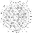
図1は、本実施形態に係るマルチコアファイバの長手方向に垂直な断面における構造を示す図である。図1に示すように、本実施形態のマルチコアファイバ1は、複数のコア要素10a,10b,10c及び複数の第2コア21と、それぞれのコア要素10a,10b,10cを囲む外側クラッド30を備える。
図1は、本実施形態に係るマルチコアファイバの長手方向に垂直な断面における構造を示す図である。図1に示すように、本実施形態のマルチコアファイバ1は、複数のコア要素10a,10b,10c及び複数の第2コア21と、それぞれのコア要素10a,10b,10cを囲む外側クラッド30を備える。
コア要素10aは、第1コア11aと、第1コア11aの外周面を隙間なく囲む内側クラッド12aと、内側クラッド12aの外周面を隙間なく囲み、外側クラッド30に外周面が隙間なく囲まれる低屈折率層13aとを有している。また、コア要素10bは、第1コア11bと、第1コア11bの外周面を隙間なく囲む内側クラッド12bと、内側クラッド12bの外周面を隙間なく囲み、外側クラッド30に外周面が隙間なく囲まれる低屈折率層13bとを有している。また、コア要素10cは、第1コア11cと、第1コア11cの外周面を隙間なく囲む内側クラッド12cと、内側クラッド12cの外周面を隙間なく囲み、外側クラッド30に外周面が隙間なく囲まれる低屈折率層13cとを有している。また、それぞれの第2コア21は外側クラッド30で隙間なく囲まれている。なお、以下の説明で単にコアという場合、第1コア11a~11c及び第2コア21の両方を意味する場合がある。
図1に示すように、外側クラッド30の中心軸を囲むように3つのコア要素10aと3つのコア要素10bとが配置されている。具体的には、それぞれのコア要素10aとそれぞれのコア要素10bとが互い違い配置され、3つのコア要素10aの第1コア11a及び3つのコア要素10bの第1コア11bがそれぞれ正六角形の頂点に位置するように配置されている。
ここで、この正六角形を基準として三角格子を描く、すなわち当該正六角形のそれぞれの頂点を格子点とする三角格子を描く。この場合、三角格子を形成する三角形はそれぞれ正三角形となり、上記正六角形の辺が三角形の辺となる。なお、図1では、各三角格子の格子点が点で示されている。このように三角格子を描くと、図1に示すように、それぞれのコア要素10a~10cの第1コア11a~11c及び第2コア21は、格子点上に配置されることとなる。
また、この正六角形で囲まれる格子点を第1層LY1とすると、第1層LY1上に位置する格子点は1個となる。本実施形態では、この格子点が外側クラッド30の中心軸上に位置しているが、格子点が外側クラッド30の中心軸から多少ずれても良い。図1に示すように第1層LY1上に位置する格子点上には外側クラッド30が位置しておりコアが非配置とされる。
上記のように第1層LY1を定義すると、上記の正六角形の各頂点から成る層が第2層LY2となり、第2層LY2のそれぞれの格子点上には、コア要素10aの第1コア11a及びコア要素10bの第1コア11bが交互に配置されることとなる。
また、第2層LY2の各格子点と外側に隣り合う各格子点から成る層を第3層LY3とすると、第3層LY3の各格子点上にはコア要素10cの第1コア11cと第2コア21とが交互に配置される。本実施形態では、第2コア21が第3層LY3の互いに隣り合う格子点を結ぶことで形成される六角形の各頂点上に配置されており、第1コア11cが第3層LY3における六角形の辺上の格子点上に配置されている。
また、第3層LY3の各格子点と外側に隣り合う各格子点から成る層を第4層LY4とすると、第4層LY4の6個の格子点上にコアが非配置とされ、第4層LY4の他の12個の格子点上に6個のコア要素10aの第1コア11a及び6個のコア要素10bの第1コア11bがそれぞれ配置され、かつ、第3層LY3上に配置されているそれぞれの第2コア21が第4層LY4のコアが非配置とされる格子点と隣り合っている。本実施形態では、第4層LY4のコアが非配置とされる格子点は、第4層LY4の互いに隣り合う格子点を結ぶことで形成される六角形の各頂点上に位置する格子点とされる。また、第4層LY4のそれぞれの辺上には格子点が2個ずつ位置し、それぞれの辺上に位置する格子点上には、コア要素10aの第1コア11aとコア要素10bの第1コア11bとが1個ずつ配置される。
また、本実施形態のマルチコアファイバ1では、第4層LY4の各格子点と外側で隣り合う格子点上にはコアが配置されていない。こうして、コア要素10a同士、及び、コア要素10b同士、及び、コア要素10c同士、及び、第2コア21同士は、互いに隣り合わず、それぞれのコア要素10a,10b,10c及び第2コア21は配置される。また、上記のようにコア要素10a,10b,10c、第2コア21が配置されることで、本実施形態のマルチコアファイバ1では30個のコアが配置されている。
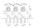
図2は、図1に示すマルチコアファイバ1のそれぞれのコア要素10a~10c及び第2コアの屈折率、実効屈折率を示す図である。図2では、コア要素10a、コア要素10b、コア要素10c、第2コア21を並べて、それぞれのコア要素10a~10c及び第2コア21の間を外側クラッド30で埋めた場合について、屈折率を実線で示している。また図2では、コア要素10a~10c及び第2コア21の実効屈折率を破線で示している。
本実施形態では、各コア要素10a,10b,10cの各第1コア11a,11b,11c及び第2コア21の直径が異なるようにされている。例えば、第1コア11aの半径が4.76μmとされ、第1コア11bの半径が4.62μmとされ、第1コア11cの半径が4.47μmとされ、第2コア21の半径が4.68μmとされる。また、本実施形態では、それぞれのコア要素10a~10cの内側クラッド12a~12cの外径が異なっている。例えば、内側クラッド12aの半径(外周面の半径)が8.09μmとされ、内側クラッド12bの半径が7.85μmとされ、内側クラッド12cの半径7.60μmとされる。内側クラッド12a~12cの半径がそれぞれ上記例示の大きさであり、第1コア11a~11cの半径が上記例示の大きさである場合、第1コア11aの半径と内側クラッド12aの半径との比と、第1コア11bの半径と内側クラッド12bの半径との比と、第1コア11cの半径と内側クラッド12cの半径の比は、互いに概ね同じ値とされる。また、本実施形態では、それぞれのコア要素10a~10cの低屈折率層13a~13cの厚みは互いに異なっている。例えば、低屈折率層13aの厚みが4.76μmとされ、低屈折率層13bの厚みが4.62μmとされ、低屈折率層13cの厚みが5.36μmとされる。この場合、第1コア11a~11cの半径が上記例示の大きさであれば、低屈折率層13aと第1コア11aの半径との比は1.0となり、低屈折率層13bと第1コア11bの半径との比は1.0となり、低屈折率層13cと第1コア11cの半径との比は1.2となる。
また、外側クラッド30の外径Rは、例えば156μm以上230μm以下とされ、それぞれの格子点の間隔、すなわち、互いに隣り合うコアの中心間距離Λは、例えば20μm以上34μm以下とされ、第4層LY4上に配置される第1コア11a,11bから外側クラッド30の外周面までの距離は、例えば25μm以上45μm以下とされる。
また、コア要素10aの第1コア11aの屈折率n11aは、内側クラッド12aの屈折率n12aよりも高く、低屈折率層13aの屈折率n13aは、内側クラッド12aの屈折率n12a及び外側クラッド30の屈折率n30よりも低くされている。同様に、コア要素10bの第1コア11bの屈折率n11bは、内側クラッド12bの屈折率n12bよりも高く、低屈折率層13bの屈折率n13bは、内側クラッド12bの屈折率n12b及び外側クラッド30の屈折率n30よりも低くされており、コア要素10cの第1コア11cの屈折率n11cは、内側クラッド12cの屈折率n12cよりも高く、低屈折率層13cの屈折率n13cは、内側クラッド12cの屈折率n12c及び外側クラッド30の屈折率n30よりも低くされている。なお、本実施形態では、内側クラッド12a,12b,12cの屈折率n12a~n12cは互いに等しく、外側クラッド30の屈折率n30と同じ屈折率とされている。また、第2コア21の屈折率n21は外側クラッド30の屈折率n30より高くされている。
このようにそれぞれのコア要素10a~10cを屈折率の観点から見る場合に、低屈折率層13a~13cはそれぞれ溝状となり、それぞれのコア要素10a~10cはトレンチ構造を有している。このような、トレンチ構造にすることにより、マルチコアファイバ1のそれぞれの第1コア11a~11cを伝搬する光の損失を抑制することができる。
マルチコアファイバ1は、このような屈折率を有するため、例えば、外側クラッド30及びそれぞれの内側クラッド12a~12cはドーパントが何ら添加されていない石英から成り、それぞれの第1コア11a~11c及び第2コア21は、ゲルマニウム等の屈折率を上げるドーパントが添加された石英から成り、低屈折率層13a~13cは、フッ素等の屈折率を下げるドーパントが添加された石英等から成る。また、上記のように第1コア11a~11c、第2コア21の屈折率が異なる場合には、第1コア11a~11c、第2コア21に添加されるドーパントの量が適宜変えられる。
なお、上記と異なり、内側クラッド12a~12cの屈折率が外側クラッド30の屈折率と異なるようにされても良く、この場合、コア要素10a~10cの実効屈折率が互いに異なる限りにおいて、内側クラッド12a~12cの屈折率が互いに同じでも良く互いに異なっていても良い。内側クラッド12a~12cの屈折率が外側クラッド30と異なる場合、内側クラッド12a~12c必要なドーパントが添加される。或いは、外側クラッド30にドーパントが適宜添加されても良い。
また、本実施形態では、それぞれの第1コア11a,11b,11c及び第2コア21の屈折率n11a,n11b,n11c,n21は互いに異なっており、例えば、外側クラッド30に対する第1コア11aの比屈折率差Δ11aは0.338%とされ、外側クラッド30に対する第1コア11bの比屈折率差Δ11bは0.305%とされ、外側クラッド30に対する第1コア11cの比屈折率差Δ11cは0.273%とされ、外側クラッド30に対する第2コア21の比屈折率差Δ21は0.388%とされる。
また、本実施形態では、それぞれの低屈折率層13a,13b,13cの屈折率が互いに等しくされ、例えば、外側クラッド30に対するそれぞれの低屈折率層13a,13b,13cの比屈折率差は、-0.7%とされる。
上記のようにマルチコアファイバ1を構成するそれぞれの部材の径や屈折率が定められることで、それぞれのコア要素10a~10c及び第2コア21の実効屈折率は互いに異なっている。例えば、マルチコアファイバ1を構成するそれぞれの部材の径や屈折率が上記の例示のように定められる場合、波長1550nmの基本モードの光において、コア要素10aの実効屈折率は1.45241450とされ、コア要素10bの実効屈折率は1.45190751とされ、コア要素10cの実効屈折率は1.45141253とされる。なお、図2では、それぞれのコア要素10a~10c及び第2コア21の実効屈折率が上記例示の状態について破線で示している。このようにコア要素10a~10cの実効屈折率の観点からそれぞれのコア要素10a~10cは3種類に分類できる。また、第2コア21の実効屈折率は1.45304244とされる。上記のように、コア要素10a同士、及び、コア要素10b同士、及び、コア要素10c同士、及び、第2コア21同士は、互いに隣り合わないため、マルチコアファイバ1において、互いに隣り合うコア要素同士、及び、互いに隣り合うコア要素と第2コアの実効屈折率は互いに異なる。
また、マルチコアファイバ1を構成するそれぞれの部材の径や屈折率が上記の例示のように定められる場合、波長1550nmの基本モードの光において、コア要素10aの実効断面積は80.2μm2となり、コア要素10bの実効断面積は80.3μm2となり、コア要素10cの実効断面積は80.2μm2となり、第2コア21の実効断面積は80.0μm2となり、それぞれのコア要素10a~10c及び第2コア21の実効断面積は概ね等しくなる。
また、マルチコアファイバ1を構成するそれぞれの部材の径や屈折率が上記の例示のように定められる場合、LP11モードの光に対して、コア要素10aのカットオフ波長は1.53μmとなり、コア要素10bのカットオフ波長は1.35μmとなり、コア要素10cのカットオフ波長は1.39μmとなり、第2コア21のカットオフ波長は1.53μmとなる。
ここで、上記の第1コア11a~11c及び第2コア21の半径r1及び外側クラッド30に対する比屈折率差Δ1、及び、低屈折率層13a~13cの外側クラッド30に対する比屈折率差Δt、及び、第1コア11a~11cの半径r1と内側クラッド12a~12cの半径r2の比r2/r1、及び、第1コア11a~11cの半径r1と低屈折率層13a~13cの厚みWとの比W/r1、コア要素10a~10c及び第2コア21の波長1550nmの基本モードの光における実効コア断面積Aeff及びLP11モードの光に対するカットオフ波長λccをコア要素10a~10c、第2コアで分類して下記表1に示す。

このようにマルチコアファイバ1の各パラメータが定められる場合、外側クラッド30の外径は、例えば228μmとされる。また、例えば、このようなパラメータとされることで、それぞれのコア要素10a~10c及び第2コア21は、波長が1530nm以上の波長帯域の光をシングルモードで伝搬することができる。
次に互いに隣り合うコア、すなわち互いに隣り合うコア要素同士或いは互いに隣り合うコア要素と第2コア21の実効屈折率差と、互いに隣り合うコア要素同士或いは互いに隣り合うコア要素と第2コア21のクロストークがピークとなるマルチコアファイバ1の曲げ半径との関係について説明する。
一般的にマルチコアファイバにおいて、互いに隣り合うコア間のクロストークがピークとなる曲げ半径Rpkは、次の式(1)で与えられる。ただし、下記式(1)において、neff1は互いに隣り合うコアおける一方のコアの実効屈折率であり、neff2は互いに隣り合うコアにおける他方のコアの実効屈折率であり、Δneffは互いに隣り合うコアの実効屈折率差とされる。また、Λは互いに隣り合うコアの中心間距離(コア間距離)であり、本実施形態のマルチコアファイバ1であれば三角格子の格子間距離に一致する。

ところで、通常光ファイバはケーブル化して使用されるが,ケーブル内で光ファイバに加わる最小の曲げ半径は数百mmであることが知られている。従って、クロストークがピークとなる光ファイバの曲げ半径Rpkが、この最小の曲げ半径より小さければ、光ファイバの通常の使用環境下において、クロストークを十分に抑制できると考えられる。従って、コア間距離Λが20μm~34μmの範囲において、本実施形態のマルチコアファイバ1のクロストークが最大となる曲げ半径Rpkが100mmより小さくなるように、互いに隣り合うコアの実効屈折率差Δneffが設定されれば良い。さらに、曲げ半径Rpkが、光ファイバの最小の曲げ半径100mmよりもさらに30%以上の余裕をもった70mm以下であれば、光ファイバの通常の使用環境下において、クロストークをさらに抑制できると考えられる。
例えば、マルチコアファイバ1において、上記表1のようにそれぞれのパラメータが定められ、コア間距離Λが30μmとされる場合、互いに隣り合うコア要素間やコア要素と第2コア21との実効屈折率差Δneff、及び、クロストークが最大となる曲げ半径Rpkは、以下の表2の通りとなる。
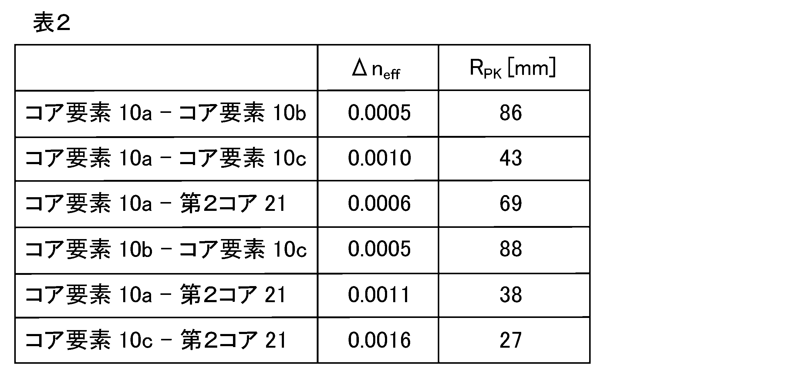
表2に示す通り、上記パラメータとされることで、互いに隣り合うコア要素間やコア要素と第2コア21の実効屈折率差Δneffは、0.0005以上とされ、クロストークが最大となる曲げ半径Rpkは100mmより小さくなる。
以上説明したように本実施形態のマルチコアファイバ1によれば、少なくとも30個のコアを配置することができる。
また、第2層LY2に配置されるそれぞれのコア要素10a,10bは、第1層LY1のコアが非配置の格子点と隣り合うと共に、第3層LY3に配置される第2コア21の1個と隣り合う。従って、第2層LY2に配置される何れのコア要素10a,10bからも高次モードの光を逃げ易くすることができる。また、第3層LY3に配置されるそれぞれの第2コア21は、第4層LY4のコアが非配置とされる格子点と隣り合うため、これら第2コア21からも高次モードの光を逃げ易くすることができる。また、第3層に配置されるそれぞれのコア要素10cは、第3層LY3に配置される第2コア21の2つと隣り合うため、第3層LY3に配置されるそれぞれのコア要素10cから高次モードの光を逃げ易くすることができる。また、第4層LY4に配置されるそれぞれのコア要素10a,10bは、第4層LY4のコアが非配置とされる格子点と隣り合う。従って、第4層LY4に配置されるそれぞれのコア要素10a,10bから高次モードの光を逃げ易くすることができる。こうして、それぞれのコアのカットオフ波長が長波長化することを抑制することができる。
また、全ての第1コア11a~11c及び第2コア21において、互いに隣合うコア間には低屈折率層が配置される。さらに、互いに隣り合うコア要素同士や互いに隣り合うコア要素と第2コア21の実効屈折率差が異なる。従って、互いに隣り合うコア要素同士や互いに隣り合うコア要素と第2コア21のクロストークを抑制することができる。
以上のように本実施形態のマルチコアファイバ1によれば、クロストーク及びカットオフ波長の長波長化を抑制しつつ配置されるコアの数を多くできる。
また、本実施形態のマルチコアファイバ1では、第2コア21が第3層LY3の互いに隣り合う格子点を結ぶことで形成される六角形の各頂点上に配置される。このため、それぞれの第2コア21間に必ずコア要素10a~10cのいずれかが位置し、低屈折率層を有しない第2コア21間のクロストークをより適切に低減することができる。また、全てのコア要素10a~10cは、コアが非配置とされる少なくとも1個の格子点及び少なくとも1個の第2コア21と隣り合う。つまり、全てのコア要素10a~10cは、高次モードが逃げ易い少なくとも2カ所の格子点と隣り合う。一方、全ての第2コア21は、コアが非配置とされる1個の格子点と隣り合うと共に5つのコア要素により囲まれる。つまり、全ての第2コア21は、高次モードが逃げ易い格子点の1つのみと隣り合う。ところで、隣接するコア要素やコアの影響を無視すると、低屈折率層で囲まれない第2コア21の方が、低屈折率層13a~13cを有するコア要素10a~10cよりも高次モードが逃げ易い。従って、本実施形態のマルチコアファイバ1によれば、コア要素10a~10cと第2コア21との間で、高次モードの逃げ易さのバランスをとることができる。
また、本実施形態のマルチコアファイバ1では、第4層LY4のコアが非配置とされる格子点は、第4層LY4の互いに隣り合う格子点を結ぶことで形成される六角形の各頂点上に位置する。このように第4層LY4の六角形の頂点にコアが非配置とされることで、この頂点にコアが配置される場合よりも外側クラッド30の外径を小さくすることができる。
(第2実施形態)
次に、本発明の第2実施形態について図3を参照して詳細に説明する。なお、第1実施形態と同一又は同等の構成要素については、同一の参照符号を付して特に説明する場合を除き重複する説明は省略する。
次に、本発明の第2実施形態について図3を参照して詳細に説明する。なお、第1実施形態と同一又は同等の構成要素については、同一の参照符号を付して特に説明する場合を除き重複する説明は省略する。
図3は、本実施形態に係るマルチコアファイバの長手方向に垂直な断面図である。図3に示すように、本実施形態のマルチコアファイバ2は、第4層LY4のコアが非配置とされる格子点が第4層LY4の互いに隣り合う格子点を結ぶことで形成される六角形の各辺上に位置する点において、第1実施形態のマルチコアファイバ1と異なる。具体的には、本実施形態では、第4層LY4の六角形の各頂点上にコア要素10aの第1コア11aが位置する。
このようなマルチコアファイバ2の構成によれば、第3層LY3における六角形の辺上の格子点上に配置されるコア要素10cが第4層LY4におけるコアが非配置とされる格子点と隣り合う。従って、コア要素10cからより高次モードの光を逃げ易くすることができる。
また、本実施形態のように第4層LY4にコア要素10a,10bの配置とすることで、第4層LY4のコアが非配置とされる格子点の位置やコア要素10a,10bの配置位置が、マルチコアファイバ2の両端で異なる。従って、コアを識別するマーカが無い場合でも、コアの種類を特定することができる。
(第3実施形態)
次に、本発明の第3実施形態について図4を参照して詳細に説明する。なお、第2実施形態と同一又は同等の構成要素については、同一の参照符号を付して特に説明する場合を除き重複する説明は省略する。
次に、本発明の第3実施形態について図4を参照して詳細に説明する。なお、第2実施形態と同一又は同等の構成要素については、同一の参照符号を付して特に説明する場合を除き重複する説明は省略する。
図4は、本実施形態に係るマルチコアファイバの長手方向に垂直な断面図である。図4に示すように、本実施形態のマルチコアファイバ3は、第2コア21が第3層LY3の互いに隣り合う格子点を結ぶことで形成される六角形の各辺上に配置される点において、第2実施形態のマルチコアファイバ2と異なる。
このように第2コア21が配置されることで、第3層LY3上に配置されるコア要素10cは、第3層LY3の六角形の各頂点上に配置される。
また、本実施形態のマルチコアファイバ3であっても、第2実施形態のマルチコアファイバ2と同様にして、コアを識別するマーカが無い場合でも、コアの種類を特定することができる。
以上、本発明について、実施形態を例に説明したが、本発明はこれらに限定されるものではない。
例えば、上記実施形態において、コア要素10a~10cは屈折率の観点から3種類としたが、4種類以上のコア要素を用いても良い。例えば、コア要素10aを実効屈折率が互いに異なる2種類のコア要素に更に分類しても良い。ただしこの場合においても2種類に分けられたそれぞれのコア要素10aは、他のコア要素10b,10cや第2コア21と異なる実効屈折率とされる。同様に第2コア21が互いに異なる実効屈折率の2種類以上のコアとされても良い。この場合であっても、それぞれの第2コア21は、それぞれのコア要素10a~10cの実効屈折率と異なる実効屈折率とされる。
また、上記実施形態において、第5層目を想定し、第5層目にコアを配置しても良い。仮に第5層目の格子状の全てにコア要素が配置されたとしても、第4層目のコア要素10a,10bは、コアが非配置とされる格子点と隣り合うため高次モードの光を逃げ易くすることができる。
以下、実施例及び比較例を挙げて本発明の内容をより具体的に説明するが、本発明はこれに限定されるものでは無い。
表1に記載のパラメータを用いて第1実施形態のマルチコアファイバ1を作製した。なお、外側クラッド30の外径を228μmとし、コア間距離を30μmとした。従って、作製したマルチコアファイバ1は、上記表2より、クロストークがピークとなる曲げ半径Rpkが100mm以下となる。
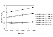
次に作製したマルチコアファイバ1のクロストークを波長1550nmの光、波長1590nmの光、波長1625nmの光について測定した。条長が9.6kmにおけるクロストークを24回測定し、それぞれの測定値を電力結合理論により100kmにおけるクロストークに換算した値とした。なお、この測定においてマルチコアファイバ1の曲げ半径を155mmとした。
この結果を表3及び図5に示す。なお、実線は、それぞれの波長のクロストークの平均値を最小二乗法を用いて計算した近似直線である
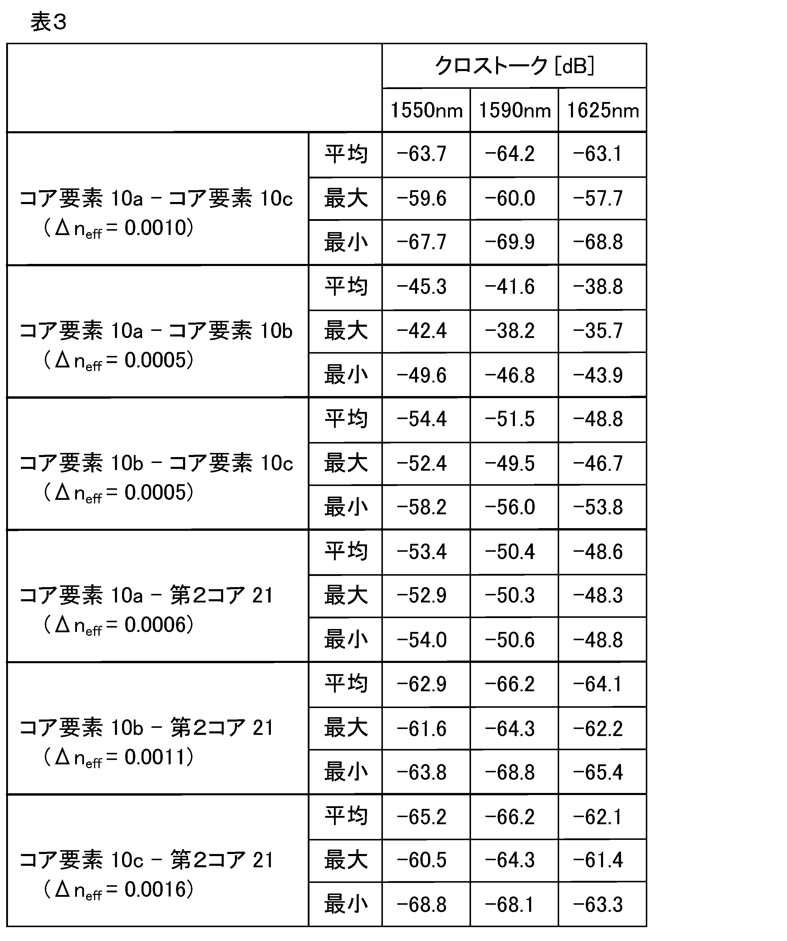
表3及び図6より、条長が100kmにおいて、波長1530nmから1625nmの光(Cバンド帯からLバンド帯)において、クロストークが-37dBより小さい結果となった。実用上支障のない小さなクロストークとなった。
以上の実施例の結果より、本発明のマルチコアファイバによれば、クロストークが抑制できることが示された。
以上説明したように、本発明によれば、クロストーク及びカットオフ波長の長波長化を抑制しつつも、配置されるコアの数を多くできるマルチコアファイバが提供される。
1,2,3・・・マルチコアファイバ
10a,10b,10c・・・コア要素
11a,11b,11c・・・第1コア
12a,12b,12c・・・内側クラッド
13a,13b,13c・・・低屈折率層
21・・・第2コア
30・・・外側クラッド
LY1・・・第1層
LY2・・・第2層
LY3・・・第3層
LY4・・・第4層
10a,10b,10c・・・コア要素
11a,11b,11c・・・第1コア
12a,12b,12c・・・内側クラッド
13a,13b,13c・・・低屈折率層
21・・・第2コア
30・・・外側クラッド
LY1・・・第1層
LY2・・・第2層
LY3・・・第3層
LY4・・・第4層
Claims (11)
- 第1コアと、前記第1コアの外周面を囲む内側クラッドと、前記内側クラッドよりも低い屈折率とされると共に前記内側クラッドを囲む低屈折率層とを有する複数のコア要素と、
複数の第2コアと、
前記第1コア及び前記第2コアよりも低い屈折率とされると共に前記低屈折率層よりも高い屈折率とされ、それぞれの前記コア要素及びそれぞれの第2コアとを囲む外側クラッドと、
を備え、
前記コア要素の実効屈折率と前記第2コアの実効屈折率とは互いに異なり、
前記複数のコア要素は、実効屈折率が互いに異なる少なくとも3種類のコア要素に分類でき、
前記外側クラッドの中心を囲む正六角形の各頂点を基準とした三角格子において、前記各頂点で囲まれる格子点を第1層とし、前記各頂点上に位置する格子点から成る層を第2層とし、前記第2層の各格子点と外側に隣り合う各格子点から成る層を第3層とし、前記第3層の各格子点と外側に隣り合う各格子点から成る層を第4層とする場合に、
前記第1層の格子点上にはコアが非配置とされ、
前記第2層の各格子点上には前記コア要素の前記第1コアが配置され、
前記第3層の各格子点上には前記コア要素の前記第1コアと前記第2コアとが交互に配置され、
前記第4層では6個の格子点上にはコアが非配置とされ他の格子点上には前記コア要素の前記第1コアが配置され、
それぞれの前記第2コアは前記第4層のコアが非配置とされる格子点と隣り合い
互いに隣り合う前記コア要素同士の実効屈折率は互いに異なる
ことを特徴とするマルチコアファイバ。 - 前記第2コアは、前記第3層の互いに隣り合う格子点を結ぶことで形成される六角形の各頂点上に配置される
ことを特徴とする請求項1に記載のマルチコアファイバ。 - 前記第4層のコアが非配置とされる格子点は、前記第4層の互いに隣り合う格子点を結ぶことで形成される六角形の各頂点上に位置する
ことを特徴とする請求項2に記載のマルチコアファイバ。 - 前記第4層のコアが非配置とされる格子点は、前記第4層の互いに隣り合う格子点を結ぶことで形成される六角形の各辺上に位置する
ことを特徴とする請求項2に記載のマルチコアファイバ。 - 前記第2コアは、前記第3層の互いに隣り合う格子点を結ぶことで形成される六角形の各辺上に配置される
ことを特徴とする請求項1に記載のマルチコアファイバ。 - 前記外側クラッドの外径が230μm以下とされ、
前記格子点の間隔が30μm以下とされる
ことを特徴とする請求項1から5のいずれか1項に記載のマルチコアファイバ。 - 互いに隣り合う前記コア要素間及び互いに隣り合う前記コア要素と前記第2コア間のクロストークの大きさが、半径100mmより小さい曲げ半径でピークとなる
ことを特徴とする請求項1から6のいずれか1項に記載のマルチコアファイバ。 - 波長が1550nmの光が前記コア要素及び第2コアを伝搬する場合に、互いに隣り合う前記コア要素間及び互いに隣り合う前記コア要素と前記第2コア間のクロストークが100km当たり-37dB以下とされる
ことを特徴とする請求項1から7のいずれか1項に記載のマルチコアファイバ。 - 前記コア要素及び前記第2コアは波長が1530nm以上の光をシングルモードで伝搬する
ことを特徴とする請求項1から8のいずれか1項に記載のマルチコアファイバ。 - 互いに隣り合う前記コア要素間及び互いに隣り合う前記コア要素と前記第2コア間の実効屈折率の差が0.0005以上である
ことを特徴とする請求項1から9のいずれか1項に記載のマルチコアファイバ。 - それぞれの前記コア要素及びそれぞれの第2コアの実効断面積が等しい
ことを特徴とする
ことを特徴とする請求項1から10のいずれか1項に記載のマルチコアファイバ。
Priority Applications (3)
| Application Number | Priority Date | Filing Date | Title |
|---|---|---|---|
| EP16749293.3A EP3171205B1 (en) | 2015-02-12 | 2016-02-10 | Multicore fiber |
| US15/501,493 US9817183B2 (en) | 2015-02-12 | 2016-02-10 | Multicore fiber |
| CN201680001424.7A CN106461858B (zh) | 2015-02-12 | 2016-02-10 | 多芯光纤 |
Applications Claiming Priority (2)
| Application Number | Priority Date | Filing Date | Title |
|---|---|---|---|
| JP2015-025211 | 2015-02-12 | ||
| JP2015025211A JP6050847B2 (ja) | 2015-02-12 | 2015-02-12 | マルチコアファイバ |
Publications (1)
| Publication Number | Publication Date |
|---|---|
| WO2016129650A1 true WO2016129650A1 (ja) | 2016-08-18 |
Family
ID=56615353
Family Applications (1)
| Application Number | Title | Priority Date | Filing Date |
|---|---|---|---|
| PCT/JP2016/054015 Ceased WO2016129650A1 (ja) | 2015-02-12 | 2016-02-10 | マルチコアファイバ |
Country Status (5)
| Country | Link |
|---|---|
| US (1) | US9817183B2 (ja) |
| EP (1) | EP3171205B1 (ja) |
| JP (1) | JP6050847B2 (ja) |
| CN (1) | CN106461858B (ja) |
| WO (1) | WO2016129650A1 (ja) |
Cited By (1)
| Publication number | Priority date | Publication date | Assignee | Title |
|---|---|---|---|---|
| WO2018168170A1 (ja) * | 2017-03-17 | 2018-09-20 | 株式会社フジクラ | マルチコアファイバ |
Families Citing this family (12)
| Publication number | Priority date | Publication date | Assignee | Title |
|---|---|---|---|---|
| JP2016171208A (ja) * | 2015-03-12 | 2016-09-23 | 株式会社フジクラ | 光ファイバ、ファイバアンプ、及びファイバレーザ |
| JP6340342B2 (ja) * | 2015-05-27 | 2018-06-06 | 株式会社フジクラ | マルチコアファイバ |
| US10545283B2 (en) | 2016-05-11 | 2020-01-28 | Intuitive Surgical Operations, Inc. | Redundant core in multicore optical fiber for safety |
| CN109283613A (zh) * | 2018-11-26 | 2019-01-29 | 北京交通大学 | 一种低芯间串扰多芯光纤 |
| JP7326933B2 (ja) * | 2019-07-03 | 2023-08-16 | 住友電気工業株式会社 | マルチコア光ファイバ |
| JP7389644B2 (ja) | 2019-12-26 | 2023-11-30 | 株式会社フジクラ | マルチコアファイバ、光ファイバケーブル、及び光コネクタ |
| JP7902112B2 (ja) * | 2020-03-18 | 2026-08-07 | コーニング インコーポレイテッド | マイクロベンドが改善された直径の減少した多芯光ファイバ |
| US12360309B2 (en) * | 2020-10-09 | 2025-07-15 | Sumitomo Electric Industries, Ltd. | Multi-core optical fiber and multi-core optical fiber cable |
| JP7528703B2 (ja) * | 2020-10-09 | 2024-08-06 | 住友電気工業株式会社 | マルチコア光ファイバおよびマルチコア光ファイバケーブル |
| CN113777696B (zh) * | 2021-08-24 | 2022-06-10 | 燕山大学 | 一种低串扰大容量少模光纤 |
| US12032200B2 (en) * | 2021-12-28 | 2024-07-09 | Sterlite Technologies Limited | Trench assisted multi-core optical fiber with reduced crosstalk |
| EP4700446A1 (en) | 2024-08-12 | 2026-02-25 | Sterlite Technologies Limited | Multicore fiber having alternated cores with and without trench |
Citations (3)
| Publication number | Priority date | Publication date | Assignee | Title |
|---|---|---|---|---|
| JP2012181282A (ja) * | 2011-02-28 | 2012-09-20 | Fujikura Ltd | マルチコアファイバ |
| JP5168702B2 (ja) * | 2008-10-03 | 2013-03-27 | 国立大学法人横浜国立大学 | マルチコアファイバのコア配置方法 |
| JP2014164269A (ja) * | 2013-02-27 | 2014-09-08 | Fujikura Ltd | マルチコアファイバ |
Family Cites Families (12)
| Publication number | Priority date | Publication date | Assignee | Title |
|---|---|---|---|---|
| CN100397116C (zh) * | 2006-04-29 | 2008-06-25 | 南开大学 | 宽带单偏振单模双芯光子晶体光纤 |
| CN100495093C (zh) * | 2007-09-14 | 2009-06-03 | 中国科学院上海光学精密机械研究所 | 强耦合的多芯光纤 |
| CN101339269B (zh) * | 2008-08-12 | 2010-06-02 | 江苏大学 | 一种光纤波分复用器 |
| JP5678679B2 (ja) | 2010-01-22 | 2015-03-04 | 住友電気工業株式会社 | マルチコアファイバ |
| CN201859245U (zh) * | 2010-11-04 | 2011-06-08 | 深圳市雅信通光缆有限公司 | 多芯数一管式通信光缆 |
| JP5595888B2 (ja) * | 2010-12-09 | 2014-09-24 | 株式会社フジクラ | マルチコアファイバ |
| JP5245019B2 (ja) | 2011-03-02 | 2013-07-24 | 株式会社フジクラ | マルチコアファイバ |
| JP2013020074A (ja) * | 2011-07-11 | 2013-01-31 | Hitachi Cable Ltd | マルチコアファイバ |
| JP5819682B2 (ja) * | 2011-09-05 | 2015-11-24 | 株式会社フジクラ | 通信用マルチコアファイバ |
| WO2014133057A1 (ja) * | 2013-02-27 | 2014-09-04 | 株式会社フジクラ | マルチコアファイバ |
| JP5860024B2 (ja) * | 2013-11-25 | 2016-02-16 | 株式会社フジクラ | マルチコアファイバ |
| JP6177994B2 (ja) * | 2014-03-07 | 2017-08-09 | 株式会社フジクラ | マルチコアファイバ |
-
2015
- 2015-02-12 JP JP2015025211A patent/JP6050847B2/ja active Active
-
2016
- 2016-02-10 WO PCT/JP2016/054015 patent/WO2016129650A1/ja not_active Ceased
- 2016-02-10 CN CN201680001424.7A patent/CN106461858B/zh not_active Expired - Fee Related
- 2016-02-10 EP EP16749293.3A patent/EP3171205B1/en active Active
- 2016-02-10 US US15/501,493 patent/US9817183B2/en active Active
Patent Citations (3)
| Publication number | Priority date | Publication date | Assignee | Title |
|---|---|---|---|---|
| JP5168702B2 (ja) * | 2008-10-03 | 2013-03-27 | 国立大学法人横浜国立大学 | マルチコアファイバのコア配置方法 |
| JP2012181282A (ja) * | 2011-02-28 | 2012-09-20 | Fujikura Ltd | マルチコアファイバ |
| JP2014164269A (ja) * | 2013-02-27 | 2014-09-08 | Fujikura Ltd | マルチコアファイバ |
Non-Patent Citations (1)
| Title |
|---|
| MASANORI KOSHIBA ET AL.: "Heterogeneous multi-core fibers: proposal and design principle", IEICE ELECTRONICS EXPRESS, vol. 6, no. 2, 25 January 2009 (2009-01-25), pages 98 - 103, XP002635350 * |
Cited By (2)
| Publication number | Priority date | Publication date | Assignee | Title |
|---|---|---|---|---|
| WO2018168170A1 (ja) * | 2017-03-17 | 2018-09-20 | 株式会社フジクラ | マルチコアファイバ |
| JP2018155972A (ja) * | 2017-03-17 | 2018-10-04 | 株式会社フジクラ | マルチコアファイバ |
Also Published As
| Publication number | Publication date |
|---|---|
| EP3171205A1 (en) | 2017-05-24 |
| EP3171205A4 (en) | 2018-03-21 |
| JP2016148761A (ja) | 2016-08-18 |
| EP3171205B1 (en) | 2019-04-03 |
| CN106461858A (zh) | 2017-02-22 |
| CN106461858B (zh) | 2019-05-31 |
| US20170235043A1 (en) | 2017-08-17 |
| US9817183B2 (en) | 2017-11-14 |
| JP6050847B2 (ja) | 2016-12-21 |
Similar Documents
| Publication | Publication Date | Title |
|---|---|---|
| JP6050847B2 (ja) | マルチコアファイバ | |
| JP6722271B2 (ja) | マルチコアファイバ | |
| JP5916525B2 (ja) | マルチコアファイバ | |
| JP6177994B2 (ja) | マルチコアファイバ | |
| JP5855351B2 (ja) | マルチコアファイバ | |
| JP6532748B2 (ja) | マルチコアファイバ | |
| JP5990419B2 (ja) | 光学入出力デバイス | |
| JP5771025B2 (ja) | マルチコアファイバ | |
| JP5808767B2 (ja) | マルチコアファイバ | |
| WO2015001990A1 (ja) | マルチコア光ファイバおよびマルチコア光ファイバケーブル | |
| JP2015184371A (ja) | 偏波保持光ファイバ | |
| US9557476B2 (en) | Multi-core fiber | |
| JPWO2014133057A1 (ja) | マルチコアファイバ | |
| JP2012203036A (ja) | 光伝送路 | |
| JP6321589B2 (ja) | 光ファイバ | |
| WO2017130487A1 (ja) | マルチコアファイバ | |
| WO2016190228A1 (ja) | マルチコアファイバ | |
| WO2017130426A1 (ja) | 光デバイス | |
| JP6096268B2 (ja) | マルチコアファイバ | |
| WO2018168170A1 (ja) | マルチコアファイバ | |
| JP2014098832A (ja) | ハイブリッドマルチコアファイバ | |
| WO2018150867A1 (ja) | マルチコアファイバ、及び、これを用いたマルチコアファイバテープ | |
| JP7732816B2 (ja) | マルチコアファイバおよびマルチコアファイバの製造方法 | |
| JP5160477B2 (ja) | 光ファイバ |
Legal Events
| Date | Code | Title | Description |
|---|---|---|---|
| 121 | Ep: the epo has been informed by wipo that ep was designated in this application |
Ref document number: 16749293 Country of ref document: EP Kind code of ref document: A1 |
|
| WWE | Wipo information: entry into national phase |
Ref document number: 15501493 Country of ref document: US |
|
| REEP | Request for entry into the european phase |
Ref document number: 2016749293 Country of ref document: EP |
|
| WWE | Wipo information: entry into national phase |
Ref document number: 2016749293 Country of ref document: EP |
|
| NENP | Non-entry into the national phase |
Ref country code: DE |