WO2016129780A1 - 순간가열장치 - Google Patents
순간가열장치 Download PDFInfo
- Publication number
- WO2016129780A1 WO2016129780A1 PCT/KR2015/012136 KR2015012136W WO2016129780A1 WO 2016129780 A1 WO2016129780 A1 WO 2016129780A1 KR 2015012136 W KR2015012136 W KR 2015012136W WO 2016129780 A1 WO2016129780 A1 WO 2016129780A1
- Authority
- WO
- WIPO (PCT)
- Prior art keywords
- heating
- flow path
- water
- unit
- path forming
- Prior art date
- Legal status (The legal status is an assumption and is not a legal conclusion. Google has not performed a legal analysis and makes no representation as to the accuracy of the status listed.)
- Ceased
Links
Images




Classifications
-
- F—MECHANICAL ENGINEERING; LIGHTING; HEATING; WEAPONS; BLASTING
- F24—HEATING; RANGES; VENTILATING
- F24H—FLUID HEATERS, e.g. WATER OR AIR HEATERS, HAVING HEAT-GENERATING MEANS, e.g. HEAT PUMPS, IN GENERAL
- F24H1/00—Water heaters, e.g. boilers, continuous-flow heaters or water-storage heaters
- F24H1/10—Continuous-flow heaters, i.e. heaters in which heat is generated only while the water is flowing, e.g. with direct contact of the water with the heating medium
-
- F—MECHANICAL ENGINEERING; LIGHTING; HEATING; WEAPONS; BLASTING
- F24—HEATING; RANGES; VENTILATING
- F24H—FLUID HEATERS, e.g. WATER OR AIR HEATERS, HAVING HEAT-GENERATING MEANS, e.g. HEAT PUMPS, IN GENERAL
- F24H1/00—Water heaters, e.g. boilers, continuous-flow heaters or water-storage heaters
- F24H1/10—Continuous-flow heaters, i.e. heaters in which heat is generated only while the water is flowing, e.g. with direct contact of the water with the heating medium
- F24H1/101—Continuous-flow heaters, i.e. heaters in which heat is generated only while the water is flowing, e.g. with direct contact of the water with the heating medium using electric energy supply
- F24H1/102—Continuous-flow heaters, i.e. heaters in which heat is generated only while the water is flowing, e.g. with direct contact of the water with the heating medium using electric energy supply with resistance
- F24H1/105—Continuous-flow heaters, i.e. heaters in which heat is generated only while the water is flowing, e.g. with direct contact of the water with the heating medium using electric energy supply with resistance formed by the tube through which the fluid flows
-
- F—MECHANICAL ENGINEERING; LIGHTING; HEATING; WEAPONS; BLASTING
- F24—HEATING; RANGES; VENTILATING
- F24H—FLUID HEATERS, e.g. WATER OR AIR HEATERS, HAVING HEAT-GENERATING MEANS, e.g. HEAT PUMPS, IN GENERAL
- F24H1/00—Water heaters, e.g. boilers, continuous-flow heaters or water-storage heaters
- F24H1/10—Continuous-flow heaters, i.e. heaters in which heat is generated only while the water is flowing, e.g. with direct contact of the water with the heating medium
- F24H1/12—Continuous-flow heaters, i.e. heaters in which heat is generated only while the water is flowing, e.g. with direct contact of the water with the heating medium in which the water is kept separate from the heating medium
- F24H1/14—Continuous-flow heaters, i.e. heaters in which heat is generated only while the water is flowing, e.g. with direct contact of the water with the heating medium in which the water is kept separate from the heating medium by tubes, e.g. bent in serpentine form
- F24H1/16—Continuous-flow heaters, i.e. heaters in which heat is generated only while the water is flowing, e.g. with direct contact of the water with the heating medium in which the water is kept separate from the heating medium by tubes, e.g. bent in serpentine form helically or spirally coiled
- F24H1/162—Continuous-flow heaters, i.e. heaters in which heat is generated only while the water is flowing, e.g. with direct contact of the water with the heating medium in which the water is kept separate from the heating medium by tubes, e.g. bent in serpentine form helically or spirally coiled using electrical energy supply
-
- F—MECHANICAL ENGINEERING; LIGHTING; HEATING; WEAPONS; BLASTING
- F24—HEATING; RANGES; VENTILATING
- F24H—FLUID HEATERS, e.g. WATER OR AIR HEATERS, HAVING HEAT-GENERATING MEANS, e.g. HEAT PUMPS, IN GENERAL
- F24H9/00—Details
- F24H9/0005—Details for water heaters
- F24H9/001—Guiding means
- F24H9/0015—Guiding means in water channels
- F24H9/0021—Sleeves surrounding heating elements or heating pipes, e.g. pipes filled with heat transfer fluid, for guiding heated liquid
-
- F—MECHANICAL ENGINEERING; LIGHTING; HEATING; WEAPONS; BLASTING
- F24—HEATING; RANGES; VENTILATING
- F24H—FLUID HEATERS, e.g. WATER OR AIR HEATERS, HAVING HEAT-GENERATING MEANS, e.g. HEAT PUMPS, IN GENERAL
- F24H9/00—Details
- F24H9/18—Arrangement or mounting of grates or heating means
-
- F—MECHANICAL ENGINEERING; LIGHTING; HEATING; WEAPONS; BLASTING
- F24—HEATING; RANGES; VENTILATING
- F24H—FLUID HEATERS, e.g. WATER OR AIR HEATERS, HAVING HEAT-GENERATING MEANS, e.g. HEAT PUMPS, IN GENERAL
- F24H9/00—Details
- F24H9/18—Arrangement or mounting of grates or heating means
- F24H9/1809—Arrangement or mounting of grates or heating means for water heaters
- F24H9/1818—Arrangement or mounting of electric heating means
-
- H—ELECTRICITY
- H05—ELECTRIC TECHNIQUES NOT OTHERWISE PROVIDED FOR
- H05B—ELECTRIC HEATING; ELECTRIC LIGHT SOURCES NOT OTHERWISE PROVIDED FOR; CIRCUIT ARRANGEMENTS FOR ELECTRIC LIGHT SOURCES, IN GENERAL
- H05B3/00—Ohmic-resistance heating
- H05B3/40—Heating elements having the shape of rods or tubes
- H05B3/42—Heating elements having the shape of rods or tubes non-flexible
- H05B3/46—Heating elements having the shape of rods or tubes non-flexible heating conductor mounted on insulating base
-
- F—MECHANICAL ENGINEERING; LIGHTING; HEATING; WEAPONS; BLASTING
- F24—HEATING; RANGES; VENTILATING
- F24H—FLUID HEATERS, e.g. WATER OR AIR HEATERS, HAVING HEAT-GENERATING MEANS, e.g. HEAT PUMPS, IN GENERAL
- F24H2250/00—Electrical heat generating means
- F24H2250/02—Resistances
Definitions
- the present invention relates to an instantaneous heating device for heating the introduced water to a predetermined temperature within a relatively fast time to supply the user, and more particularly, to an instantaneous heating device in which deformation of a heating flow path heated while water flows can be minimized. It is about.
- the hot water tank is a device that supplies the user with the stored water heated to a predetermined temperature.
- the temperature of the stored water must always be maintained at a predetermined temperature. For example, in a hot water tank, when the temperature of the water heated to a predetermined temperature is lower than the predetermined temperature, reheating to a predetermined temperature or more is repeated, so that the temperature of the stored water always maintains the predetermined temperature.
- the temperature of the stored water must be maintained at a predetermined temperature at all times, and thus a relatively large amount of energy is required to heat the water. There was a problem with hygiene due to stains.
- the instantaneous heating device heats the water to a predetermined temperature within a relatively fast time to supply the user.
- Such an instant heating device is generally configured to directly heat the flowing water, and for this purpose, a heating flow path is formed in the instantaneous heating device while the water is heated.
- the heating channel directly heats the flowing water, and the length of the heating is increased as much as possible, so that the length thereof is as long as possible.
- the heating channel is formed by combining several members rather than one member. For example, one member is fitted into another member to form a heating flow path.
- the heating flow path is formed to have a predetermined volume so that the water does not flow locally while flowing.
- the heating flow path is deformed at the time of formation of the heating flow path or when the instantaneous heating device is used, so that the predetermined flow volume does not have the aforementioned volume.
- the water flowing in the heating channel is locally overheated at the portion where the heating channel is deformed as described above, and water is generated when discharged through the discharge member such as cock or facet.
- the present invention is made by recognizing at least any one of the above-mentioned demands or problems.
- One aspect of the present invention is to minimize the deformation of the heating flow path formed in the instantaneous heating device so that the water is heated while flowing.
- Another aspect of the present invention is that the water flowing in the heating flow path is locally overheated to minimize the generation of water when discharged to the outside.
- Another aspect of the object of the present invention is to prevent the user from overheating and safety accidents such as flying on the splashed water when discharged.
- An instantaneous heating device for realizing at least one of the above problems may include the following features.
- Instantaneous heating device is the water inlet unit to which water is introduced from the outside; A flow portion through which water introduced into the inflow portion flows; Heating unit for heating the water flowing in the flow unit; And a water extraction unit for discharging water heated by the heating unit to the outside.
- the flow unit may include a flow path forming member disposed inside the heating unit, and a close pressurizing unit which closely adheres the flow path forming member to the heating unit so that a heating flow path is formed between the heating unit and the flow path forming member.
- the close pressing portion may include a pressing member inserted into the insertion portion formed in the flow passage forming member to press the flow passage forming member toward the heating portion.
- the close pressing portion may further include a pressing force member for applying a pressing force to the pressing member.
- the pressing member may be formed in plural, and when joined to each other, a hollow cylinder, an elliptical cylinder, or a polygonal cylinder corresponding to the shape of the insert may be formed.
- the pressing force member may be in the shape of a cylinder, an elliptical cylinder or a polygonal column corresponding to a hollow cylinder, an elliptic cylinder or a polygonal cylinder formed by combining a plurality of pressing members.
- the outer diameter of the pressing force member may be larger than the inner diameter of the hollow cylinder, the elliptical cylinder, or the polygonal cylinder formed by the combination of the pressing members.
- the pressing force member may be provided with a fitting protrusion to be fitted to the fitting hole formed in the insertion portion.
- the flow path forming member may be made of silicon.
- a flow path forming groove forming a heating flow path may be formed at an outer circumference of the flow path forming member.
- the flow path forming groove may be spiral.
- an inlet flow passage and an outlet flow passage may be formed in the inlet portion and the outlet portion, respectively.
- a portion of the inlet portion and a portion of the outlet portion may be inserted into one side and the other side of the insertion portion formed inside the flow path forming member.
- a first connection hole and a second connection hole may be formed at one side and the other side of the flow path forming member, respectively to connect the inflow passage and the outlet passage, and the heating passage.
- the inlet or outlet may include a temperature sensor for measuring the temperature of the water flowing through the inlet or outlet.
- the heating unit may further include a heating member in which a flow path forming member is disposed; And a heater attached to the heating member to heat the heating member. It may include.
- the heater may be a surface heating heater.
- the cover part includes an inlet part and an inlet side cover member covering a part of the heating part; And an outlet side cover member coupled to the inlet side cover member and covering the rest of the heating unit and the outlet unit; It may include.
- a heating flow path that is heated while the water flows between the heating part and the flow path forming member may be formed in close contact with the heating part by the close pressing portion.
- the deformation of the heating passage can be minimized.
- the water flowing in the heating flow path may be locally superheated to minimize the generation of water when discharged to the outside.
- FIG. 1 is a perspective view of one embodiment of the instantaneous heating apparatus according to the present invention.
- Figure 2 is an exploded perspective view of one embodiment of the instantaneous heating apparatus according to the present invention.
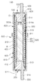
- FIG. 3 is a cross-sectional view taken along line AA ′ of FIG. 1.
- FIG 4 and 5 are views showing that a heating flow path is formed between the heating part and the flow path forming member by the flow-forming member being in close contact with the heating part by the close pressing portion of the instantaneous heating apparatus according to the present invention.
- Figure 6 is a cross-sectional view like Figure 3 showing the operation of one embodiment of the instantaneous heating apparatus according to the present invention.
- Figure 1 is a perspective view of one embodiment of the instantaneous heating device according to the present invention
- Figure 2 is an exploded perspective view of one embodiment of the instantaneous heating device according to the present invention
- Figure 3 is a cross-sectional view taken along line AA 'of Figure 1 .
- FIGS. 4 and 5 are views showing that a heating flow path is formed between the heating part and the flow path forming member by being in close contact with the heating part by the close pressing portion of the instantaneous heating apparatus according to the present invention.
- 6 is a cross-sectional view as shown in Figure 3 showing the operation of one embodiment of the instantaneous heating apparatus according to the present invention.
- One embodiment of the instantaneous heating apparatus according to the present invention may include the acquisition unit 200, the flow unit 300, the heating unit 400, and the water extraction unit 500.
- an acquisition channel 210 may be formed in the acquisition unit 200.
- the access passage 210 may be, for example, a '-' shaped as shown in FIG. 3.
- the shape of the acquisition flow path 210 is not specifically limited, Any shape may be used as long as water is available and can flow.
- the acquisition unit 200 may include an acquisition nipple 220.
- a part of the aforementioned acquisition passage 210 may be formed in the acquisition nipple 220.
- the intake nipple 220 may be connected to a water supply source (not shown) such as a storage tank or a water filter, for example, by a fitting member (not shown).
- water from the water supply source may be obtained in the inflow channel 210 of the inflow nipple 220 and flow in the inflow channel 210.
- a sealing member insertion groove 230 may be formed in the inlet 200.
- a sealing member O such as an O-ring as illustrated in FIGS. 2 and 3 may be inserted.
- the acquisition part 200 and the acquisition side cover member 610 included in the cover part 600 to be described later covering the acquisition part 200 may be sealed.
- the acquisition unit 200 may include a temperature sensor (not shown).
- the temperature sensor may be provided in the acquisition unit 200 to measure the temperature of the water flowing through the acquisition passage 210 of the acquisition unit 200.
- the temperature sensor may be provided in the intake nipple 220 of the intake unit 200.
- the position provided in the acquisition unit 200 of the temperature sensor is not particularly limited, and may be provided at any position of the acquisition unit 200.
- the temperature of the water flowing through the water inlet flow path 210 measured by the temperature sensor is, for example, in the heating part 400 when heating the water flowing in the heating flow path R by the heating part 400 to be described later. Can be used to adjust the amount of heat generated.
- water flowing into the flow part 300 flows into the inflow part 200, that is, the inflow path 210 of the inflow part 200.
- the flow part 300 may include a flow path forming member 310.
- the flow path forming member 310 may be disposed in the heating unit 400 as shown in FIG. 3.
- a flow path forming groove 312 may be formed at an outer circumference of the flow path forming member 310.
- a heating flow path R may be formed between the heating part 400 and the flow path forming member 310.
- the water flowing into the inflow channel 210 of the inflow unit 200 may flow the heating channel R as illustrated in FIG. 6.
- the flow path forming grooves 312 formed in the flow path forming member 310 may be spiral, for example, as shown in FIG. 2. As a result, the heating flow path R is also spiral.
- the shape of the flow path forming groove 312 is not particularly limited, and any shape such as a zigzag shape may be used as long as the heating flow path R is formed between the heating part 400 and the flow path forming member 310.
- a first connection hole 313 connecting the inflow passage 210 and the heating passage R may be formed at one side of the flow passage forming member 310, for example.
- a part of the acquisition part 200 is inserted into one side of the insertion part 311 formed inside the flow path forming member 310, for example, the lower part, so that the acquisition flow path 210 is formed. It can be connected to the heating flow path (R) by one connection hole (313).
- a second connection hole is formed at the other side of the flow path forming member 310, for example, at an upper portion of the water outlet portion 500 to connect the water outlet passage 510 and the heating passage R to be described later. 314 may be formed. And, a part of the water extraction part 500 is inserted into the other side, for example, the upper portion of the insertion portion 311 of the flow path forming member 310, the water extraction flow path 510 is heated by the second connection hole 314 ( R).
- the water flowing in the heating flow path R may move to the water outlet flow passage 510 of the water outlet part 500 through the second connection hole 314 and flow out the water flow passage 510 to be discharged to the outside. have.
- the insertion hole 311a of the flow path forming member 310 may be formed as shown in FIG. 3.
- the insertion hole 311a of the insertion portion 311 is included in the flow portion 300 as shown in FIGS. 3 and 5 and formed in the pressing force member 322 included in the close pressing portion 320 to be described later.
- the fitting protrusion 322a may be fitted. As a result, the pressing force applying member 322 can be stably fixed in the insertion portion 311 of the flow path forming member 310.
- the flow path forming member 310 may be made of silicon. Silicone has relatively low heat deformation and does not adversely affect water such as carcinogens and other harmful substances on contact with water.
- the heating flow path R is formed between the heating part 400 by forming the flow path forming member 310 with silicon, the heating flow path R is not deformed or closed by thermal deformation, and the heating flow path R The water flowing through may not be altered.
- a portion of the flow path forming member 310 other than the flow path forming groove 312 may be easily adhered to the heating part 400 by the close pressing portion 320, thereby easily forming the heating flow path R. .
- the material constituting the flow path forming member 310 is not limited to the above-described silicone, any material known in the art can be used as long as the thermal deformation is relatively low, the water does not deteriorate when contacted with water, and the elasticity is relatively good. .
- the flow part 300 may further include a close pressing part 320.
- the close contact pressure unit 320 includes the flow path forming member 310 such that the heating flow path R is formed between the heating part 400 and the flow path forming member 310. ) Can be adhered to.
- the flow passage R is formed by fitting the flow path forming member 310 to the heating part 400 to form the heating flow path R between the flow path forming member 310 and the heating part 400. ) Deformation can be minimized.
- the water flowing in the heating channel may be locally overheated, thereby minimizing the generation of water when it is discharged to the outside, and a safety accident such as flying on the splashed water when the user is locally overheated may not occur.
- the close pressing unit 320 may include a pressing member 321.
- the pressing member 321 may be inserted into the insertion portion 311 of the flow path forming member 310 as shown in FIG.
- the pressing member 321 may press the flow path forming member 310 toward the heating part 400.
- the flow path forming member 310 is expanded by its elasticity so that a portion of the flow path forming member 310 other than the flow path forming groove 312 may be in close contact with the heating part 400. have.
- the pressing member 321 may be a plurality. For example, as shown in FIG. 2, there may be two pressing members 321. However, the number of the pressing members 321 is not particularly limited and may be any number.
- the pressing member 321 may form a hollow cylindrical, elliptical or polygonal cylinder corresponding to the shape of the insertion portion 311 of the flow path forming member 310 when joined together.
- the two pressing members 321 have a shape in which a hollow cylinder is divided into two vertically, and when joined together, a hollow cylinder may be formed.
- the pressing member 321 may be three or more, and when combined with each other, may form an elliptic cylinder or a polygonal cylinder.
- both the pressing member 321 is radially inserted in the insertion portion 311 of the flow path forming member 310, That is, the flow path forming member 310 may be urged in the radially outward direction.
- portions of the flow path forming member 310 other than the flow path forming grooves 312 may be expanded by elasticity to be in close contact with the heating part 400.
- the close pressing unit 320 may further include a pressing force member 322.
- the pressing force applying member 322 may apply a pressing force to the pressing member 321.
- the pressing force acting member 322 may be a cylinder corresponding to a hollow cylinder, an elliptic cylinder, or a polygonal cylinder formed by combining the plurality of pressing members 321 as shown in FIG. 2, or may be an elliptical cylinder or a polygonal column shape. have.
- the outer diameter D1 of the pressing force acting member 322 may be larger than the inner diameter D2 of the hollow cylinder, the elliptical cylinder, or the polygonal cylinder formed by combining the pressing members 321.
- a hollow cylinder or an elliptical cylinder formed by the plurality of pressing members 321 inserted into the insertion portion 311 of the flow path forming member 310 by the pressing force acting member 322.
- a pressing force acts on the pressing member 321 to press the flow path forming member 310 radially outward while the pressure member 321 is opened.
- the heating unit 400 may heat the water flowing in the flow unit 300. That is, as shown in FIG. 6, the heating unit 400 may heat water flowing through the heating flow path R formed together with the flow path forming groove 312 of the flow path forming member 310.
- the water flowing through the heating flow path R is directly heated by the heating unit 400, the water can be heated to a desired predetermined temperature in a relatively fast time.
- the heating unit 400 may include a heating member 410 and a heater 420.
- the flow path forming member 310 may be disposed inside the heating member 410. Accordingly, portions of the flow path forming member 310 other than the flow path forming grooves 312 may be in close contact with the inner surface of the flow path forming member 310 to form the heating flow path R. FIG.
- the heating member 410 may be, for example, a hollow cylindrical shape as shown in FIG. 2.
- the shape of the heating member 410 is not particularly limited, and any shape may be used as long as the flow path forming member 310 may be disposed therein, such as a hollow elliptic cylinder shape or a polygonal cylinder shape.
- the heating member 410 may be made of stainless steel. Accordingly, since the heating member 410 is heated relatively quickly by the heater 420 which will be described later because of high thermal conductivity, it is possible to heat the water flowing in the heating flow path R more quickly. And it may not be corroded by water.
- the material constituting the heating member 410 is not particularly limited, and any material may be used as long as the material has high thermal conductivity and corrosion resistance to water.
- the heater 420 may be attached to the heating member 410 as shown in FIG. Then, the heating member 410 may be heated.
- the heater 420 may be a surface heating heater. However, the heater 420 is not particularly limited, and any heaters 420 can be used as long as the heating member 410 can be heated.
- the water heated in the heating unit 400 may be discharged to the outside by the water extraction unit 500.
- the withdrawal passage 510 may be formed in the water extraction unit 500.
- the water flow passage 510 may have a 'b' shape, for example, as shown in FIG. 3.
- the shape of the water discharge passage 510 is not particularly limited, and may be any shape as long as the water heated in the heating unit 400 can be discharged to the outside.
- the water extraction unit 500 may include a water extraction nipple 520.
- the water extraction nipple 520 may be formed with a portion of the above water extraction passage 510.
- the outlet nipple 520 may be connected to a discharge member (not shown), such as a cock or a facet, by, for example, a fitting member (not shown).
- the water heated by the heating unit 400 while flowing the heating channel R moves to the water extraction channel 510 and then the water extraction channel 520 of the water extraction nipple 520. 510 may be discharged to the outside.
- a sealing member insertion groove 530 may be formed in the water outlet part 500.
- a sealing member O such as an O-ring as illustrated in FIGS. 2 and 3 may be inserted.
- the water extraction part 500 and the water extraction side cover member 620 included in the cover part 600 to be described later covering the water extraction part 500 may be sealed.
- Water extraction unit 500 may also include a temperature sensor (not shown).
- the temperature sensor may be provided in the water extraction unit 500 to measure the temperature of the water flowing in the water extraction passage 510 of the water extraction unit 500.
- the temperature sensor may be provided in the water extraction nipple 520 of the water extraction unit 500.
- the position provided in the water extraction unit 500 of the temperature sensor is not particularly limited, and may be provided at any position of the water extraction unit 500.
- the temperature of the water flowing through the water discharge passage 510 measured by the temperature sensor for example, the heating unit so as not to overheat the water when heating the water flowing in the heating passage (R) by the above-described heating unit 400 It can be used to adjust the amount of heat generated at (400).
- One embodiment of the instantaneous heating device 100 according to the present invention may further include a cover 600 as shown in Figs.
- the cover part 600 may cover the inlet part 200, the heating part 400, and the outlet part 500 as shown in FIGS. 1 and 3. Even if the pressure of the water obtained by the cover unit 600 to the inlet 200 is relatively high, the flow unit 300 including the inlet 200, the heating unit 400, and the outlet unit 500 is stable. So you can stay connected.
- the cover part 600 may include an inlet side cover member 610 and an outlet side cover member 620.
- the inlet side cover member 610 may cover the inlet 200 and a part of the heating unit 400 as shown in FIG. To this end, the inlet side cover member 610 may have a cylindrical shape with an open top.
- the shape of the acquisition side cover member 610 is not specifically limited, Any shape may be used as long as it covers the acquisition part 200 and a part of heating part 400.
- a first exposure hole 611 may be formed on a lower surface of the inlet side cover member 610, for example, the inlet side cover member 610. Accordingly, the inlet nipple 220 of the inlet unit 200 may be exposed to the outside through the first exposure hole 611. As a result, the discharge member such as the cock or the facet can be easily connected to the water intake nipple 220.
- a coupling groove 612 may be formed inside the open upper portion of the inlet side cover member 610, for example, the inlet side cover member 610.
- Coupling groove 612 may be a 'b' shape as shown in FIG.
- the coupling groove 612 may be inserted into the coupling protrusion 622 to be described later formed on the water outlet side cover member 620. As a result, the water outlet side cover member 620 may be coupled to the water supply side cover member 610.
- the shape of the coupling groove 612 is not particularly limited, and the coupling protrusion 622 of the water outlet side cover member 620 is inserted, and the water outlet side cover member 620 may be coupled to the water inlet cover member 610. Any shape may be used as long as it is a shape.
- the outlet side cover member 620 may be coupled to the inlet side cover member 610. Then, the rest of the heating unit 400 and the water extraction unit 500 may be covered.
- the water extraction side cover member 620 may have a cylindrical shape with a lower opening.
- the shape of the water outlet side cover member 620 is not particularly limited, and may be any shape as long as it is coupled to the water outlet side cover member 610 and covers the rest of the heating unit 400 and the water outlet unit 500. .
- a second exposure hole 621 may be formed on the top surface of the water extraction side cover member 620, for example, the water extraction side cover member 620. Accordingly, the water extraction nipple 520 of the water extraction unit 500 may be exposed to the outside through the second exposure hole 621. Then, the water extraction nipple 520 can be easily connected to the water supply source.
- Coupling protrusion 622 may be formed on the outer side of the open lower portion of the outlet side cover member 620, for example, the outlet side cover member 620.
- a lower portion of the outlet side cover member 620 may be inserted into an upper portion of the inlet side cover member 610. Then, the engaging projection 622 of the water outlet side cover member 620 is inserted into the aforementioned coupling groove 612 of the water inlet cover member 610, the water outlet side cover member 620 is the water inlet cover member 610. Can be coupled to.
- the shape of the coupling protrusion 622 is not particularly limited, and may be any shape as long as it can be inserted into the coupling groove 612 of the inlet-side cover member 610.
- An installation hole 623 may be formed in the water outlet side cover member 620.
- a bimetal (not shown) may be installed or an electric wire connected to the heater 420 may pass through the installation hole 623.
- the flow path forming member is in close contact with the heating unit by the close pressing unit, and a heating flow path is formed while the water flows between the heating unit and the flow channel forming member.
- the deformation of the heating channel can be minimized, the water flowing in the heating channel can be locally overheated, and the occurrence of water bleeding when discharged to the outside can be minimized. You can prevent it from happening.
- the instantaneous heating apparatus described above may not be limitedly applied to the configuration of the above-described embodiment, but the embodiments may be configured by selectively combining all or some of the embodiments so that various modifications can be made. .
Landscapes
- Engineering & Computer Science (AREA)
- Physics & Mathematics (AREA)
- Thermal Sciences (AREA)
- Chemical & Material Sciences (AREA)
- Combustion & Propulsion (AREA)
- Mechanical Engineering (AREA)
- General Engineering & Computer Science (AREA)
- Fluid Mechanics (AREA)
- Instantaneous Water Boilers, Portable Hot-Water Supply Apparatuses, And Control Of Portable Hot-Water Supply Apparatuses (AREA)
- Details Of Fluid Heaters (AREA)
Abstract
순간가열장치를 개시한다. 본 발명의 일실시예에 따른 순간가열장치는 외부로부터 물이 유입되는 입수부; 상기 입수부에 유입된 물이 유동하는 유동부; 상기 유동부에서 유동하는 물을 가열하는 가열부; 및 상기 가열부에 의해서 가열된 물이 외부로 배출되는 출수부; 를 포함하며, 상기 유동부는 상기 가열부 내부에 배치되는 유로형성부재와, 상기 가열부와 유로형성부재 사이에 가열유로가 형성되도록 상기 유로형성부재를 상기 가열부에 밀착하는 밀착가압부를 포함할 수 있다.
Description
본 발명은 유입된 물을 비교적 빠른 시간 내에 소정 온도로 가열하여 사용자에게 공급하는 순간가열장치에 관한 것으로, 보다 상세하게는 물이 유동하면서 가열되는 가열유로의 변형이 최소화될 수 있는 순간가열장치에 관한 것이다.
온수탱크는 저장된 물을 소정 온도로 가열한 후 사용자에게 공급하는 장치이다. 이를 위해서, 온수탱크에서는 저장된 물의 온도가 항상 소정 온도를 유지하도록 해야만 한다. 예컨대, 온수탱크에서는 소정 온도로 가열된 물의 온도가 소정 온도보다 낮아지면, 소정 온도 이상으로 재가열하는 것을 반복하여, 저장된 물의 온도가 항상 소정 온도를 유지하도록 한다.
이와 같이, 온수탱크에서는 저장된 물의 온도가 항상 소정 온도를 유지하도록 해야만 하기 때문에 물의 가열에 비교적 많은 에너지가 소요되며, 온수탱크에 장기간 물이 저장되기 때문에, 온수탱크의 내부면이 물에 의해서 부식되거나 물때가 끼거나 하여 위생성에 문제가 있었다.
이러한 온수탱크의 문제점을 해결하기 위하여, 순간가열장치가 개발되었으며, 순간가열장치는 물을 비교적 빠른 시간 내에 소정 온도로 가열하여 사용자에게 공급한다.
이에 따라, 필요한 양만큼의 물만을 소정 온도로 가열하여 사용자에게 공급하기 때문에, 물의 가열에 비교적 적은 에너지가 소요되며, 물이 저장되지 않기 때문에 위생적으로 좋게 된다.
이러한 순간가열장치는 일반적으로 유동하는 물을 직접 가열하도록 구성되며, 이를 위해서 순간가열장치에는 물이 유동하면서 가열되는 가열유로가 형성된다.
가열유로는 유동하는 물에 직접 열을 가하며 열을 가하는 시간이 많아지도록, 가급적 그 길이가 최대한 길어지도록 하며, 이를 위해서 하나의 부재보다는 여러 부재를 조합하여 가열유로를 형성한다. 예컨대, 하나의 부재를 다른 부재 내부에 끼워맞춤식으로 끼워 넣어 가열유로를 형성한다.
한편, 가열유로는 물이 유동하면서 국부적으로 과열되지 않도록 소정의 체적을 가지도록 형성된다.
그러나, 전술한 바와 같이 여러 부재를 조합하여 가열유로를 형성하는 경우, 가열유로의 형성시나 순간가열장치의 사용시에 가열유로가 변형되어 전술한 소정의 체적을 가지지 못하게 되는 일이 비교적 빈번히 발생하였다.
이에 따라, 가열유로를 유동하는 물이 전술한 바와 같이 가열유로가 변형된 부분에서 국부적으로 과열되어, 콕크나 파우셋 등의 배출부재를 통해서 배출시 물튐이 발생하게 된다.
그리고, 이와 같이 물튐이 발생하면, 튄 물에 사용자가 데이는 등의 안전사고가 발생하게 된다.
본 발명은 상기와 같은 종래에서 발생하는 요구 또는 문제들 중 적어도 어느 하나를 인식하여 이루어진 것이다.
본 발명의 목적의 일 측면은 물이 유동하면서 가열되도록 순간가열장치에 형성되는 가열유로의 변형이 최소화되도록 하는 것이다.
본 발명의 목적의 다른 측면은 가열유로를 유동하는 물이 국부적으로 과열되어 외부로 배출시 물튐이 발생하는 것이 최소화되도록 하는 것이다.
본 발명의 목적의 또 다른 측면은 사용자가 과열되어 배출시 튄 물에 데이는 등의 안전사고가 발생하지 않도록 하는 것이다.
상기 과제들 중 적어도 하나의 과제를 실현하기 위한 일실시 형태와 관련된 순간가열장치는 다음과 같은 특징을 포함할 수 있다.
본 발명의 일실시 형태에 따른 순간가열장치는 외부로부터 물이 유입되는 입수부; 입수부에 유입된 물이 유동하는 유동부; 유동부에서 유동하는 물을 가열하는 가열부; 및 가열부에 의해서 가열된 물이 외부로 배출되는 출수부; 를 포함하며, 유동부는 가열부 내부에 배치되는 유로형성부재와, 가열부와 유로형성부재 사이에 가열유로가 형성되도록 유로형성부재를 가열부에 밀착하는 밀착가압부를 포함할 수 있다.
이 경우, 상기 밀착가압부는 유로형성부재 내부에 형성된 삽입부에 삽입되어 유로형성부재를 가열부 측으로 가압하는 가압부재를 포함할 수 있다.
또한, 상기 밀착가압부는 가압부재에 가압력을 작용하는 가압력작용부재를 더 포함할 수 있다.
그리고, 상기 가압부재는 복수개이며, 서로 합쳐지면 삽입부의 형상에 대응되는 중공의 원통이나 타원통 또는 다각통을 이룰 수 있다.
또한, 상기 가압력작용부재는 복수개의 가압부재가 합쳐져서 이루는 중공의 원통이나 타원통 또는 다각통에 대응되는 원기둥이나 타원기둥 또는 다각형 기둥 형상일 수 있다.
그리고, 상기 가압력작용부재의 외경은 가압부재가 합쳐져서 이루는 중공의 원통이나 타원통 또는 다각통의 내경보다 클 수 있다.
또한, 상기 가압력작용부재에는 삽입부에 형성된 끼움구멍에 끼워지는 끼움돌기가 구비될 수 있다.
그리고, 상기 유로형성부재는 실리콘으로 이루어질 수 있다.
또한, 상기 유로형성부재의 외주에는 가열유로를 이루는 유로형성홈이 형성될 수 있다.
그리고, 상기 유로형성홈은 나선형일 수 있다.
또한, 상기 입수부와 출수부에는 각각 입수유로와 출수유로가 형성될 수 있다.
그리고, 상기 입수부의 일부와 출수부의 일부는 유로형성부재의 내부에 형성된 삽입부의 일측과 타측에 각각 삽입될 수 있다.
또한, 상기 유로형성부재의 일측과 타측에는 입수유로 및 출수유로와, 가열유로를 각각 연결하는 제1연결구멍과 제2연결구멍이 각각 형성될 수 있다.
그리고, 상기 입수부 또는 출수부는 입수유로나 출수유로를 유동하는 물의 온도를 측정하는 온도센서를 포함할 수 있다.
또한, 상기 가열부는 유로형성부재가 내부에 배치되는 가열부재; 및 가열부재에 부착되어 가열부재를 가열하는 히터; 를 포함할 수 있다.
그리고, 상기 히터는 면상발열히터일 수 있다.
또한, 상기 입수부와 가열부 및 출수부를 덮는 커버부; 를 더 포함할 수 있다.
그리고, 상기 커버부는 입수부와, 가열부의 일부를 덮는 입수측 커버부재; 및 입수측 커버부재에 결합되며 가열부의 나머지와 출수부를 덮는 출수측 커버부재; 를 포함할 수 있다.
이상에서와 같이 본 발명의 실시예에 따르면, 밀착가압부에 의해서 유로형성부재가 가열부에 밀착되어 가열부와 유로형성부재 사이에 물이 유동하면서 가열되는 가열유로가 형성될 수 있다.
또한, 본 발명의 실시예에 따르면, 가열유로의 변형이 최소화될 수 있다.
그리고 또한, 본 발명의 실시예에 따르면, 가열유로를 유동하는 물이 국부적으로 과열되어 외부로 배출시 물튐이 발생하는 것이 최소화될 수 있다.
그리고 또한, 본 발명의 실시예에 따르면, 사용자가 과열되어 배출시 튄 물에 데이는 등의 안전사고가 발생하지 않도록 할 수 있다.
도1은 본 발명에 따른 순간가열장치의 일실시예의 사시도이다.
도2는 본 발명에 따른 순간가열장치의 일실시예의 분해사시도이다.
도3은 도1의 A-A'선에 따른 단면도이다.
도4와 도5는 본 발명에 따른 순간가열장치의 일실시예의 밀착가압부에 의해서 유로형성부재가 가열부에 밀착되어 가열부와 유로형성부재 사이에 가열유로가 형성되는 것을 나타내는 도면이다.
도6은 본 발명에 따른 순간가열장치의 일실시예의 작동을 나타내는 도3과 같은 단면도이다.
상기와 같은 본 발명의 특징들에 대한 이해를 돕기 위하여, 이하 본 발명의 실시예와 관련된 순간가열장치에 대하여 보다 상세하게 설명하도록 하겠다.
이하 설명되는 실시예들은 본 발명의 기술적인 특징을 이해시키기에 가장 적합한 실시예들을 기초로 하여 설명될 것이며, 설명되는 실시예들에 의해 본 발명의 기술적인 특징이 제한되는 것이 아니라, 이하, 설명되는 실시예들과 같이 본 발명이 구현될 수 있다는 것을 예시하는 것이다. 따라서, 본 발명은 아래 설명된 실시예들을 통해 본 발명의 기술 범위 내에서 다양한 변형 실시가 가능하며, 이러한 변형 실시예는 본 발명의 기술 범위 내에 속한다 할 것이다. 그리고, 이하, 설명되는 실시예의 이해를 돕기 위하여 첨부된 도면에 기재된 부호에 있어서, 각 실시예에서 동일한 작용을 하게 되는 구성요소 중 관련된 구성요소는 동일 또는 연장 선상의 숫자로 표기하였다.
이하, 도1 내지 도6을 참조로 하여 본 발명에 따른 순간가열장치의 일실시예에 대하여 설명한다.
도1은 본 발명에 따른 순간가열장치의 일실시예의 사시도이며, 도2는 본 발명에 따른 순간가열장치의 일실시예의 분해사시도이고, 도3은 도1의 A-A'선에 따른 단면도이다.
또한, 도4와 도5는 본 발명에 따른 순간가열장치의 일실시예의 밀착가압부에 의해서 유로형성부재가 가열부에 밀착되어 가열부와 유로형성부재 사이에 가열유로가 형성되는 것을 나타내는 도면이고, 도6은 본 발명에 따른 순간가열장치의 일실시예의 작동을 나타내는 도3과 같은 단면도이다.
본 발명에 따른 순간가열장치의 일실시예는 입수부(200), 유동부(300), 가열부(400) 및, 출수부(500)를 포함할 수 있다.
입수부(200)에는 도6에 도시된 바와 같이 외부로부터 물이 입수된다. 이를 위해서, 입수부(200)에는 입수유로(210)가 형성될 수 있다.
입수유로(210)는 예컨대 도3에 도시된 바와 같이 'ㄱ'자 형상일 수 있다. 그러나, 입수유로(210)의 형상은 특별히 한정되지 않고, 물이 입수되어 유동할 수 있는 형상이라면 어떠한 형상이라도 가능하다.
입수부(200)는 입수니플(220)을 포함할 수 있다. 입수니플(220)에는 전술한 입수유로(210)의 일부가 형성될 수 있다. 그리고, 입수니플(220)은, 예컨대 피팅부재(도시되지 않음) 등에 의해서 저장탱크나 정수필터 등의 물공급원(도시되지 않음)에 연결될 수 있다.
이에 따라, 도6에 도시된 바와 같이 물공급원의 물이 입수니플(220)의 입수유로(210)에 입수되어 입수유로(210)를 유동할 수 있다.
입수부(200)에는 밀봉부재 삽입홈(230)이 형성될 수 있다. 밀봉부재 삽입홈(230)에는, 예컨대 도2와 도3에 도시된 바와 같은 오링 등의 밀봉부재(O)가 삽입될 수 있다. 이에 의해서, 입수부(200)와, 입수부(200)를 덮는 후술할 커버부(600)에 포함되는 입수측 커버부재(610) 사이가 밀봉될 수 있다.
입수부(200)는 온도센서(도시되지 않음)를 포함할 수 있다. 온도센서는 입수부(200)의 입수유로(210)를 유동하는 물의 온도를 측정할 수 있도록 입수부(200)에 구비될 수 있다.
예컨대, 온도센서는 입수부(200)의 입수니플(220)에 구비될 수 있다. 그러나, 온도센서의 입수부(200)에서의 구비위치는 특별히 한정되지 않고, 입수부(200)의 어떠한 위치에도 구비될 수 있다.
또한, 온도센서에 의해서 측정된 입수유로(210)를 유동하는 물의 온도는, 예컨대 후술할 가열부(400)에 의해서 가열유로(R)를 유동하는 물을 가열할 때 가열부(400)에서의 발열량을 조절할 때 사용할 수 있다.
유동부(300)에는 도6에 도시된 바와 같이 입수부(200), 즉 입수부(200)의 입수유로(210)에 유입된 물이 유동한다.
이를 위해서, 유동부(300)는 유로형성부재(310)를 포함할 수 있다. 유로형성부재(310)는 도3에 도시된 바와 같이 가열부(400) 내부에 배치될 수 있다. 또한, 유로형성부재(310)의 외주에는 유로형성홈(312)이 형성될 수 있다.
따라서, 도3에 도시된 바와 같이 가열부(400)와 유로형성부재(310) 사이에 가열유로(R)가 형성될 수 있다. 그리고, 입수부(200)의 입수유로(210)에 유입된 물은 도6에 도시된 바와 같이 가열유로(R)를 유동할 수 있다.
유로형성부재(310)에 형성된 유로형성홈(312)은, 예컨대 도2에 도시된 바와 같이 나선형일 수 있다. 이에 따라, 가열유로(R)도 나선형이 된다.
그러나, 유로형성홈(312)의 형상은 특별히 한정되지 않고, 가열부(400)와 유로형성부재(310) 사이에 가열유로(R)가 형성되도록 하는 형상이라면 지그재그형상 등 어떠한 형상이라도 가능하다.
유로형성부재(310)의 일측, 예컨대 하부에는 도2와 도3에 도시된 바와 같이 입수유로(210)와 가열유로(R)를 연결하는 제1연결구멍(313)이 형성될 수 있다. 그리고, 도3에 도시된 바와 같이 입수부(200)의 일부가 유로형성부재(310)의 내부에 형성된 삽입부(311)의 일측, 예컨대 하부에 삽입되는 것에 의해서, 입수유로(210)가 제1연결구멍(313)에 의해서 가열유로(R)에 연결될 수 있다.
따라서, 도6에 도시된 바와 같이 입수부(200)의 입수유로(210)에 유입된 물이 제1연결구멍(313)을 통해 가열유로(R)로 이동하여 가열유로(R)를 유동할 수 있다.
도2와 도3에 도시된 바와 같이 유로형성부재(310)의 타측, 예컨대 상부에는 출수부(500)에 형성되는 후술할 출수유로(510)와 가열유로(R)를 연결하는 제2연결구멍(314)이 형성될 수 있다. 그리고, 출수부(500)의 일부가 유로형성부재(310)의 삽입부(311)의 타측, 예컨대 상부에 삽입되는 것에 의해서 출수유로(510)가 제2연결구멍(314)에 의해서 가열유로(R)에 연결될 수 있다.
이에 따라, 가열유로(R)를 유동한 물이 제2연결구멍(314)을 통해 출수부(500)의 출수유로(510)로 이동하여 출수유로(510)를 유동한 후 외부로 배출될 수 있다.
유로형성부재(310)의 전술한 삽입부(311)에는 도3에 도시된 바와 같이 끼움구멍(311a)이 형성될 수 있다. 이러한 삽입부(311)의 끼움구멍(311a)에는 도3과 도5에 도시된 바와 같이 유동부(300)에 포함되며 후술할 밀착가압부(320)에 포함되는 가압력작용부재(322)에 형성된 끼움돌기(322a)가 끼워질 수 있다. 이에 의해서, 가압력작용부재(322)가 유로형성부재(310)의 삽입부(311) 내에 안정되게 고정될 수 있다.
유로형성부재(310)는 실리콘으로 이루어질 수 있다. 실리콘은 열변형이 비교적 적으며, 물에 접촉시 발암물질 등의 유해물질이 나오는 등의 안 좋은 영향을 물에 주지 않는다.
또한, 비교적 탄성이 좋기 때문에, 후술할 바와 같이 밀착가압부(320)에 의해서 용이하게 유로형성홈(312)의 이외의 부분이 가열부(400)에 밀착되도록 하여 가열유로(R)를 형성할 수 있다.
따라서, 실리콘으로 유로형성부재(310)를 이루어 가열부(400)와의 사이에서 가열유로(R)를 형성하면, 가열유로(R)가 열변형에 의해서 변형되거나 폐쇄되지 않고, 가열유로(R)를 유동하는 물이 변질되지 않을 수 있다.
그리고, 밀착가압부(320)에 의해서 유로형성홈(312) 이외의 유로형성부재(310)의 부분이 가열부(400)에 용이하게 밀착되도록 하여 가열유로(R)를 용이하게 형성할 수 있다.
그러나, 유로형성부재(310)를 이루는 소재는 전술한 실리콘에 한정되지 않고, 열변형이 비교적 적고, 물에 접촉시 물이 변질되지 않으며, 탄성이 비교적 좋은 소재라면, 주지의 어떠한 소재라도 가능하다.
도2와 도3에 도시된 바와 같이 유동부(300)는 밀착가압부(320)를 더 포함할 수 있다. 밀착가압부(320)는 도4와 도5에 도시된 바와 같이 가열부(400)와 유로형성부재(310) 사이에 가열유로(R)가 형성되도록 유로형성부재(310)를 가열부(400)에 밀착할 수 있다.
이에 따라, 유로형성부재(310)가 가열부(400)에 끼워맞춤식으로 끼워져서 유로형성부재(310)와 가열부(400) 사이에 가열유로(R)를 형성하는 것보다, 가열유로(R)의 변형이 최소화될 수 있다.
그러므로, 가열유로를 유동하는 물이 국부적으로 과열되어 외부로 배출시 물튐이 발생하는 것이 최소화될 수 있으며, 사용자가 국부적으로 과열되어 배출시 튄 물에 데이는 등의 안전사고가 발생하지 않을 수 있다.
이를 위해서, 밀착가압부(320)는 가압부재(321)를 포함할 수 있다. 가압부재(321)는 도3과 도4에 도시된 바와 같이 유로형성부재(310)의 삽입부(311)에 삽입될 수 있다. 그리고, 가압부재(321)는 유로형성부재(310)를 가열부(400) 측으로 가압할 수 있다.
이에 따라, 도5에 도시된 바와 같이 유로형성부재(310)가 자체의 탄성에 의해서 팽창하여 유로형성홈(312) 이외의 유로형성부재(310)의 부분이 가열부(400)에 밀착될 수 있다.
이러한 가압부재(321)는 복수개일 수 있다. 예컨대, 도2에 도시된 바와 같이 가압부재(321)는 2개일 수 있다. 그러나, 가압부재(321)의 개수는 특별히 한정되지 않고, 어떠한 개수라도 가능하다.
또한, 가압부재(321)는 서로 합쳐지면 유로형성부재(310)의 삽입부(311)의 형상에 대응되는 중공의 원통형이나 타원통 또는 다각통을 이룰 수 있다. 예컨대, 도2에 도시된 바와 같이 2개의 가압부재(321)는 중공의 원통을 세로로 2등분한 형상이어서, 서로 합쳐지면 중공의 원통을 이룰 수 있다.
그러나, 전술한 바와 같이 가압부재(321)는 3개 이상일 수도 있으며, 서로 합쳐지면 타원통 또는 다각통을 이룰 수도 있다.
전술한 구성의 가압부재(321)에 의해서, 도4와 도5에 도시된 바와 같이 가압부재(321) 모두가 유로형성부재(310)의 삽입부(311)에 삽입된 상태에서, 방사상으로, 즉 반지름 바깥방향으로 유로형성부재(310)를 가압할 수 있다. 그리고, 이에 의해서 전술한 바와 같이 유로형성홈(312) 이외의 유로형성부재(310)의 부분이 탄성에 의해서 팽창하여 가열부(400)에 밀착될 수 있다.
밀착가압부(320)는 가압력작용부재(322)를 더 포함할 수 있다. 가압력작용부재(322)는 가압부재(321)에 가압력을 작용할 수 있다.
이를 위해서, 가압력작용부재(322)는 도2에 도시된 바와 같이 복수개의 가압부재(321)가 합쳐져서 이루는 중공의 원통이나 타원통 또는 다각통에 대응되는 원기둥이나, 타원기둥 또는 다각형 기둥 형상일 수 있다.
또한, 가압력작용부재(322)의 외경(D1)은 가압부재(321)가 합쳐져서 이루는 중공의 원통이나 타원통 또는 다각통의 내경(D2)보다 클 수 있다.
이에 따라, 도4와 도5에 도시된 바와 같이 가압력작용부재(322)가 유로형성부재(310)의 삽입부(311)에 삽입된 복수개의 가압부재(321)가 이루는 중공의 원통이나 타원통 또는 다각통에 삽입되면, 가압부재(321)에 가압력이 작용하여 가압부재(321) 사이가 벌어지면서 유로형성부재(310)를 반지름 방향 바깥측으로 가압하게 된다.
가열부(400)는 유동부(300)에서 유동하는 물을 가열할 수 있다. 즉, 도6에 도시된 바와 같이 가열부(400)는 유로형성부재(310)의 유로형성홈(312)과 함께 형성한 가열유로(R)를 유동하는 물을 가열할 수 있다.
이와 같이 가열유로(R)를 유동하는 물을 가열부(400)에 의해서 직접 가열하기 때문에, 비교적 빠른 시간에 물을 원하는 소정 온도까지 가열할 수 있다.
가열부(400)는 가열부재(410)와, 히터(420)를 포함할 수 있다.
가열부재(410)의 내부에는 유로형성부재(310)가 내부에 배치될 수 있다. 이에 따라, 유로형성홈(312)의 이외의 유로형성부재(310)의 부분이 유로형성부재(310)의 내면에 밀착되어 가열유로(R)를 형성할 수 있다.
가열부재(410)는 도2에 도시된 바와 같이, 예컨대 중공의 원통 형상일 수 있다. 그러나, 가열부재(410)의 형상은 특별히 한정되지 않고, 중공의 타원통 형상이거나 다각통 형상 등 유로형성부재(310)가 내부에 배치될 수 있는 형상이라면 어떠한 형상이라도 가능하다.
가열부재(410)는 스테인레스스틸로 이루어질 수 있다. 이에 따라, 가열부재(410)는 열전도율이 높아서 후술할 히터(420)에 의해서 비교적 빨리 가열되기 때문에, 가열유로(R)를 유동하는 물을 보다 신속하게 가열할 수 있다. 그리고, 물에 의해서 부식되지 않을 수도 있다.
그러나, 가열부재(410)를 이루는 소재는 특별히 한정되지 않고, 열전도율이 높고 물에 대해서 내부식성이 있는 소재라면 어떠한 소재라도 가능하다.
히터(420)는 도2에 도시된 바와 같이 가열부재(410)에 부착될 수 있다. 그리고, 가열부재(410)를 가열할 수 있다. 이러한 히터(420)는 면상발열히터일 수 있다. 그러나, 히터(420)는 특별히 한정되지 않고, 가열부재(410)를 가열할 수 있는 것이라면 전열선 등 주지의 어떠한 것이라도 가능하다.
도6에 도시된 바와 같이 출수부(500)에 의해서 가열부(400)에서 가열된 물, 즉 온수가 외부로 배출될 수 있다.
이를 위해서, 출수부(500)에는 출수유로(510)가 형성될 수 있다.
출수유로(510)는 예컨대 도3에 도시된 바와 같이 'ㄴ'자 형상일 수 있다. 그러나, 출수유로(510)의 형상은 특별히 한정되지 않고, 가열부(400)에서 가열된 물이 외부로 배출될 수 있는 형상이라면 어떠한 형상이라도 가능하다.
출수부(500)는 출수니플(520)을 포함할 수 있다. 출수니플(520)에는 전술한 출수유로(510)의 일부가 형성될 수 있다. 그리고, 출수니플(520)은, 예컨대 피팅부재(도시되지 않음) 등에 의해서 콕크나 파우셋 등의 배출부재(도시되지 않음)에 연결될 수 있다.
이에 따라, 도6에 도시된 바와 같이 가열유로(R)를 유동하면서 가열부(400)에 의해서 가열된 물, 즉 온수는 출수유로(510)로 이동한 후 출수니플(520)의 출수유로(510)를 통해 외부로 배출될 수 있다.
출수부(500)에도 밀봉부재 삽입홈(530)이 형성될 수 있다. 밀봉부재 삽입홈(530)에는, 예컨대 도2와 도3에 도시된 바와 같은 오링 등의 밀봉부재(O)가 삽입될 수 있다. 이에 의해서, 출수부(500)와, 출수부(500)를 덮는 후술할 커버부(600)에 포함되는 출수측 커버부재(620) 사이가 밀봉될 수 있다.
출수부(500)도 온도센서(도시되지 않음)를 포함할 수 있다. 온도센서는 출수부(500)의 출수유로(510)를 유동하는 물의 온도를 측정할 수 있도록 출수부(500)에 구비될 수 있다.
예컨대, 온도센서는 출수부(500)의 출수니플(520)에 구비될 수 있다. 그러나, 온도센서의 출수부(500)에서의 구비위치는 특별히 한정되지 않고, 출수부(500)의 어떠한 위치에도 구비될 수 있다.
또한, 온도센서에 의해서 측정된 출수유로(510)를 유동하는 물의 온도는, 예컨대 전술한 가열부(400)에 의해서 가열유로(R)를 유동하는 물을 가열할 때 물이 과열되지 않도록 가열부(400)에서의 발열량을 조절할 때 사용할 수 있다.
본 발명에 따른 순간가열장치(100)의 일실시예는 도1과 도2에 도시된 바와 같이 커버부(600)를 더 포함할 수 있다.
커버부(600)는 도1과 도3에 도시된 바와 같이 입수부(200)와 가열부(400) 및 출수부(500)를 덮을 수 있다. 이러한 커버부(600)에 의해서 입수부(200)에 입수되는 물의 압력이 비교적 높다고 하더라도, 입수부(200)와 가열부(400) 및 출수부(500)를 포함하여 유동부(300)가 안정되게 연결을 유지할 수 있다.
도1에 도시된 바와 같이 이러한 커버부(600)는 입수측 커버부재(610)와 출수측 커버부재(620)를 포함할 수 있다.
입수측 커버부재(610)는 도3에 도시된 바와 같이 입수부(200)와, 가열부(400)의 일부를 덮을 수 있다. 이를 위해서, 입수측 커버부재(610)는 상부가 개방된 원통 형상일 수 있다. 그러나, 입수측 커버부재(610)의 형상은 특별히 한정되지 않고, 입수부(200)와, 가열부(400)의 일부를 덮는 형상이라면 어떠한 형상이라도 가능하다.
도3에 도시된 바와 같이 입수측 커버부재(610), 예컨대 입수측 커버부재(610)의 하면에는 제1노출구멍(611)이 형성될 수 있다. 이에 따라, 입수부(200)의 입수니플(220)이 제1노출구멍(611)을 통과하여 외부에 노출될 수 있다. 그리고, 이에 의해서, 콕크나 파우셋 등의 배출부재를 용이하게 입수니플(220)에 연결시킬 수 있다.
입수측 커버부재(610), 예컨대 입수측 커버부재(610)의 개방된 상부의 내측에는 결합홈(612)이 형성될 수 있다. 결합홈(612)은 도2에 도시된 바와 같이 'ㄴ'자 형상일 수 있다.
결합홈(612)에는 출수측 커버부재(620)에 형성된 후술할 결합돌기(622)가 삽입될 수 있다. 이에 의해서, 입수측 커버부재(610)에 출수측 커버부재(620)가 결합될 수 있다.
결합홈(612)의 형상은 특별히 한정되지 않고, 출수측 커버부재(620)의 결합돌기(622)가 삽입되어, 입수측 커버부재(610)에 출수측 커버부재(620)가 결합될 수 있는 형상이라면 주지의 어떠한 형상이라도 가능하다.
출수측 커버부재(620)는 입수측 커버부재(610)에 결합될 수 있다. 그리고, 가열부(400)의 나머지와 출수부(500)를 덮을 수 있다.
이를 위해서, 출수측 커버부재(620)는 하부가 개방된 원통 형상일 수 있다. 그러나, 출수측 커버부재(620)의 형상은 특별히 한정되지 않고, 입수측 커버부재(610)에 결합되며, 가열부(400)의 나머지와 출수부(500)를 덮는 형상이라면 어떠한 형상이라도 가능하다.
도3에 도시된 바와 같이 출수측 커버부재(620), 예컨대 출수측 커버부재(620)의 상면에는 제2노출구멍(621)이 형성될 수 있다. 이에 따라, 출수부(500)의 출수니플(520)이 제2노출구멍(621)을 통과하여 외부에 노출될 수 있다. 그리고, 이에 의해서 출수니플(520)을 용이하게 물공급원에 연결할 수 있다.
출수측 커버부재(620), 예컨대 출수측 커버부재(620)의 개방된 하부의 외측에는 결합돌기(622)가 형성될 수 있다.
또한, 출수측 커버부재(620)의 하부는 입수측 커버부재(610)의 상부에 삽입될 수 있다. 그리고, 출수측 커버부재(620)의 결합돌기(622)가 입수측 커버부재(610)의 전술한 결합홈(612)에 삽입되어, 출수측 커버부재(620)가 입수측 커버부재(610)에 결합될 수 있다.
결합돌기(622)의 형상은 특별히 한정되지 않고, 입수측 커버부재(610)의 결합홈(612)에 삽입될 수 있는 형상이라면 어떠한 형상이라도 가능하다.
출수측 커버부재(620)에는 설치구멍(623)이 형성될 수 있다. 설치구멍(623)에는 바이메탈(도시되지 않음)이 설치되거나 히터(420)에 연결되는 전선 등이 통과할 수 있다.
이상에서와 같이 본 발명에 따른 순간가열장치를 사용하면, 밀착가압부에 의해서 유로형성부재가 가열부에 밀착되어 가열부와 유로형성부재 사이에 물이 유동하면서 가열되는 가열유로가 형성될 수 있으며, 가열유로의 변형이 최소화될 수 있고, 가열유로를 유동하는 물이 국부적으로 과열되어 외부로 배출시 물튐이 발생하는 것이 최소화될 수 있으며, 사용자가 과열되어 튄 물에 데이는 등의 안전사고가 발생하지 않도록 할 수 있다.
상기와 같이 설명된 순간가열장치는 상기 설명된 실시예의 구성이 한정되게 적용될 수 있는 것이 아니라, 상기 실시예들은 다양한 변형이 이루어질 수 있도록 각 실시예들의 전부 또는 일부가 선택적으로 조합되어 구성될 수도 있다.
Claims (18)
- 외부로부터 물이 유입되는 입수부;상기 입수부에 유입된 물이 유동하는 유동부;상기 유동부에서 유동하는 물을 가열하는 가열부; 및상기 가열부에 의해서 가열된 물이 외부로 배출되는 출수부; 를 포함하며,상기 유동부는 상기 가열부 내부에 배치되는 유로형성부재와, 상기 가열부와 유로형성부재 사이에 가열유로가 형성되도록 상기 유로형성부재를 상기 가열부에 밀착하는 밀착가압부를 포함하는 순간가열장치.
- 제1항에 있어서, 상기 밀착가압부는 상기 유로형성부재 내부에 형성된 삽입부에 삽입되어 상기 유로형성부재를 상기 가열부 측으로 가압하는 가압부재를 포함하는 순간가열장치.
- 제2항에 있어서, 상기 밀착가압부는 상기 가압부재에 가압력을 작용하는 가압력작용부재를 더 포함하는 순간가열장치.
- 제3항에 있어서, 상기 가압부재는 복수개이며, 서로 합쳐지면 상기 삽입부의 형상에 대응되는 중공의 원통이나 타원통 또는 다각통을 이루는 순간가열장치.
- 제4항에 있어서, 상기 가압력작용부재는 상기 복수개의 가압부재가 합쳐져서 이루는 중공의 원통이나 타원통 또는 다각통에 대응되는 원기둥이나 타원기둥 또는 다각형 기둥 형상인 순간가열장치.
- 제5항에 있어서, 상기 가압력작용부재의 외경은 상기 가압부재가 합쳐져서 이루는 중공의 원통이나 타원통 또는 다각통의 내경보다 큰 순간가열장치.
- 제3항에 있어서, 상기 가압력작용부재에는 상기 삽입부에 형성된 끼움구멍에 끼워지는 끼움돌기가 구비되는 순간가열장치.
- 제1항에 있어서, 상기 유로형성부재는 실리콘으로 이루어지는 순간가열장치.
- 제1항에 있어서, 상기 유로형성부재의 외주에는 상기 가열유로를 이루는 유로형성홈이 형성되는 순간가열장치.
- 제9항에 있어서, 상기 유로형성홈은 나선형인 순간가열장치.
- 제1항에 있어서, 상기 입수부와 출수부에는 각각 입수유로와 출수유로가 형성되는 순간가열장치.
- 제11항에 있어서, 상기 입수부의 일부와 상기 출수부의 일부는 상기 유로형성부재의 내부에 형성된 삽입부의 일측과 타측에 각각 삽입되는 순간가열장치.
- 제11항에 있어서, 상기 유로형성부재의 일측과 타측에는 상기 입수유로 및 출수유로와, 상기 가열유로를 각각 연결하는 제1연결구멍과 제2연결구멍이 각각 형성되는 순간가열장치.
- 제11항에 있어서, 상기 입수부 또는 출수부는 상기 입수유로나 출수유로를 유동하는 물의 온도를 측정하는 온도센서를 포함하는 순간가열장치.
- 제1항에 있어서, 상기 가열부는상기 유로형성부재가 내부에 배치되는 가열부재; 및상기 가열부재에 부착되어 상기 가열부재를 가열하는 히터;를 포함하는 순간가열장치.
- 제15항에 있어서, 상기 히터는 면상발열히터인 순간가열장치.
- 제1항에 있어서, 상기 입수부와 가열부 및 출수부를 덮는 커버부; 를 더 포함하는 순간가열장치.
- 제17항에 있어서, 상기 커버부는상기 입수부와, 상기 가열부의 일부를 덮는 입수측 커버부재; 및상기 입수측 커버부재에 결합되며 상기 가열부의 나머지와 출수부를 덮는 출수측 커버부재;를 포함하는 순간가열장치.
Priority Applications (5)
| Application Number | Priority Date | Filing Date | Title |
|---|---|---|---|
| CN201580075869.5A CN107250685B (zh) | 2015-02-11 | 2015-11-11 | 瞬时加热装置 |
| JP2017542436A JP6603724B2 (ja) | 2015-02-11 | 2015-11-11 | 瞬間加熱装置 |
| US15/550,526 US20180031270A1 (en) | 2015-02-11 | 2015-11-11 | Instantaneous heating apparatus |
| EP15882142.1A EP3258186B1 (en) | 2015-02-11 | 2015-11-11 | Instantaneous heating apparatus |
| ES15882142T ES2729988T3 (es) | 2015-02-11 | 2015-11-11 | Aparato de calentamiento instantáneo |
Applications Claiming Priority (2)
| Application Number | Priority Date | Filing Date | Title |
|---|---|---|---|
| KR10-2015-0020932 | 2015-02-11 | ||
| KR1020150020932A KR102322280B1 (ko) | 2015-02-11 | 2015-02-11 | 순간가열장치 |
Publications (1)
| Publication Number | Publication Date |
|---|---|
| WO2016129780A1 true WO2016129780A1 (ko) | 2016-08-18 |
Family
ID=56615711
Family Applications (1)
| Application Number | Title | Priority Date | Filing Date |
|---|---|---|---|
| PCT/KR2015/012136 Ceased WO2016129780A1 (ko) | 2015-02-11 | 2015-11-11 | 순간가열장치 |
Country Status (7)
| Country | Link |
|---|---|
| US (1) | US20180031270A1 (ko) |
| EP (1) | EP3258186B1 (ko) |
| JP (1) | JP6603724B2 (ko) |
| KR (1) | KR102322280B1 (ko) |
| CN (1) | CN107250685B (ko) |
| ES (1) | ES2729988T3 (ko) |
| WO (1) | WO2016129780A1 (ko) |
Families Citing this family (13)
| Publication number | Priority date | Publication date | Assignee | Title |
|---|---|---|---|---|
| CN105546804B (zh) * | 2016-02-05 | 2019-03-22 | 佛山市云米电器科技有限公司 | 一种用于液体加热的加热装置 |
| CN105571109B (zh) * | 2016-02-05 | 2018-11-30 | 佛山市云米电器科技有限公司 | 一种水道加热装置的密封体 |
| KR102356818B1 (ko) * | 2017-03-30 | 2022-01-28 | 코웨이 주식회사 | 온수기 |
| KR102447439B1 (ko) * | 2017-04-25 | 2022-09-27 | 엘지전자 주식회사 | 수처리 장치용 온수생성모듈 |
| KR102647077B1 (ko) * | 2017-10-11 | 2024-03-14 | 코웨이 주식회사 | 온수기 |
| US10605482B2 (en) * | 2018-02-23 | 2020-03-31 | A. O. Smith Corporation | Water heater with damper |
| KR102709697B1 (ko) * | 2018-08-09 | 2024-09-26 | 코웨이 주식회사 | 가열장치 및 이를 포함하는 온수기 |
| US11243010B2 (en) * | 2018-12-31 | 2022-02-08 | Economico, Llc | Water heater insert |
| JP7266782B2 (ja) * | 2019-01-23 | 2023-05-01 | Toto株式会社 | 瞬間式熱交換器及び衛生洗浄装置 |
| GB2586254B (en) * | 2019-08-14 | 2022-02-09 | Swedish Biomimetics 3000 Umist Tech Ltd | Mobile fluid expulsion device |
| CN110513864B (zh) * | 2019-09-06 | 2021-12-28 | 芜湖美的厨卫电器制造有限公司 | 加热器和制热设备 |
| CN113023829A (zh) * | 2021-02-09 | 2021-06-25 | 广东栗子科技有限公司 | 一种解决加热龙头结垢和加热压力大的水路及控制方法 |
| CN219141079U (zh) * | 2022-11-25 | 2023-06-06 | 厦门阿玛苏电子卫浴有限公司 | 一种双加热功能的开水器 |
Citations (5)
| Publication number | Priority date | Publication date | Assignee | Title |
|---|---|---|---|---|
| KR20100068624A (ko) * | 2008-12-15 | 2010-06-24 | 임병만 | 히터모듈 조립체 |
| KR20100119013A (ko) * | 2009-04-30 | 2010-11-09 | 임병만 | 발광다이오드를 이용한 유체가열장치 |
| KR20120047470A (ko) * | 2010-11-04 | 2012-05-14 | 이진교 | 스크류 형태의 지지체를 이용한 순간온수 발생기 |
| US20140050466A1 (en) * | 2012-08-20 | 2014-02-20 | Borgwarner Beru Systems Gmbh | Electric heating device for heating fluids |
| KR20140119618A (ko) * | 2013-04-01 | 2014-10-10 | 김재영 | 인덕션 보일러 |
Family Cites Families (12)
| Publication number | Priority date | Publication date | Assignee | Title |
|---|---|---|---|---|
| US1408634A (en) * | 1920-10-25 | 1922-03-07 | Alphonso F Passmore | Water heater |
| JPH1078259A (ja) * | 1996-09-04 | 1998-03-24 | Hitachi Ltd | 流体加熱方法及び流体加熱装置 |
| DE19737694C1 (de) * | 1997-08-29 | 1998-10-29 | August Balke Elektro Geraete G | Durchlauferhitzer für fließfähige oder pastöse, eßbare oder trinkbare Zubereitungen |
| US6118934A (en) * | 1997-11-14 | 2000-09-12 | Tseng; Chuan-Tseng | Safety protection structure for aquarium heater |
| GB2339335A (en) * | 1998-07-09 | 2000-01-19 | Strix Ltd | Controls for electric water boiling vessels |
| CN2475969Y (zh) * | 2001-01-22 | 2002-02-06 | 李万浩 | 速热温水器 |
| JP3863116B2 (ja) * | 2002-03-14 | 2006-12-27 | 株式会社小松製作所 | 流体温度調節装置 |
| FR2855359B1 (fr) * | 2003-05-19 | 2005-07-01 | Seb Sa | Dispositif de chauffage d'un liquide pour appareil electromenager, appareil electromenager equipe d'un tel dispositif. |
| US20090010625A1 (en) * | 2007-07-02 | 2009-01-08 | Emerson Electric Co. | Flow Through Heater |
| TWM397280U (en) * | 2010-05-06 | 2011-02-01 | xi-fu Chen | Vapor generating apparatus |
| KR101721135B1 (ko) * | 2010-07-07 | 2017-04-10 | 주식회사 엘지유플러스 | 능동적인 와이파이 서비스를 제공하기 위한 기지국 및 그의 동작방법, 그를 포함한 시스템 및 방법, 엑세스 포인트 서버 및 그의 동작방법 |
| CN204025870U (zh) * | 2014-08-08 | 2014-12-17 | 陈非 | 一种调节装置以及具有该调节装置的快速电热水器 |
-
2015
- 2015-02-11 KR KR1020150020932A patent/KR102322280B1/ko active Active
- 2015-11-11 EP EP15882142.1A patent/EP3258186B1/en active Active
- 2015-11-11 WO PCT/KR2015/012136 patent/WO2016129780A1/ko not_active Ceased
- 2015-11-11 CN CN201580075869.5A patent/CN107250685B/zh active Active
- 2015-11-11 ES ES15882142T patent/ES2729988T3/es active Active
- 2015-11-11 US US15/550,526 patent/US20180031270A1/en not_active Abandoned
- 2015-11-11 JP JP2017542436A patent/JP6603724B2/ja active Active
Patent Citations (5)
| Publication number | Priority date | Publication date | Assignee | Title |
|---|---|---|---|---|
| KR20100068624A (ko) * | 2008-12-15 | 2010-06-24 | 임병만 | 히터모듈 조립체 |
| KR20100119013A (ko) * | 2009-04-30 | 2010-11-09 | 임병만 | 발광다이오드를 이용한 유체가열장치 |
| KR20120047470A (ko) * | 2010-11-04 | 2012-05-14 | 이진교 | 스크류 형태의 지지체를 이용한 순간온수 발생기 |
| US20140050466A1 (en) * | 2012-08-20 | 2014-02-20 | Borgwarner Beru Systems Gmbh | Electric heating device for heating fluids |
| KR20140119618A (ko) * | 2013-04-01 | 2014-10-10 | 김재영 | 인덕션 보일러 |
Also Published As
| Publication number | Publication date |
|---|---|
| ES2729988T3 (es) | 2019-11-07 |
| EP3258186B1 (en) | 2019-03-13 |
| JP2018505380A (ja) | 2018-02-22 |
| EP3258186A4 (en) | 2018-03-21 |
| KR20160099154A (ko) | 2016-08-22 |
| CN107250685B (zh) | 2019-12-13 |
| EP3258186A1 (en) | 2017-12-20 |
| KR102322280B1 (ko) | 2021-11-09 |
| CN107250685A (zh) | 2017-10-13 |
| US20180031270A1 (en) | 2018-02-01 |
| JP6603724B2 (ja) | 2019-11-06 |
Similar Documents
| Publication | Publication Date | Title |
|---|---|---|
| WO2013129815A1 (en) | Cooling-water heating type heater | |
| WO2018199498A9 (en) | HOT WATER GENERATION MODULE FOR WATER TREATMENT APPARATUS | |
| WO2020218855A2 (en) | Aerosol generating device | |
| KR102322280B1 (ko) | 순간가열장치 | |
| WO2010098518A1 (ko) | 이중조리기구와 그 제조방법 | |
| WO2019004566A1 (ko) | 설치가 용이한 반도체 및 lcd 제조공정의 배기가스 가열용 3중 배관 가열장치 | |
| EP3182873A1 (en) | Pump and dishwasher including the same | |
| WO2022146079A1 (ko) | 정수기 | |
| WO2015106571A1 (zh) | 压力式液体速热器 | |
| WO2019050122A1 (ko) | 냉매파이프가 매립되는 방열장치의 케이싱, 이의 제조장치 및 제조방법 | |
| WO2014142561A1 (ko) | 순간 온수기 | |
| WO2020122601A1 (ko) | 제빙용 증발기 제조방법 및 제빙용 증발기 | |
| WO2018221925A1 (ko) | 전기 온수기 | |
| WO2016159626A1 (ko) | 유로관 연결 모듈 및 이를 구비하는 정수기 | |
| WO2022010212A1 (ko) | 증기압을 이용한 온수순환장치 | |
| WO2011083910A2 (ko) | 보충수밸브와 보충수연결배관 및 이들의 결합구조 | |
| WO2019172644A1 (ko) | 유로 가이드 탱크를 포함하는 비데용 온수 시스템 및 이를 이용한 온수 모드 방법 | |
| WO2022211427A1 (ko) | 화상 방지용 조리 기구 | |
| WO2019147102A1 (ko) | 난방 및 조리를 위한 스토브 어셈블리 | |
| WO2023101324A1 (en) | Aerosol generating device | |
| WO2020055054A1 (ko) | 순간온수장치 | |
| WO2011059120A1 (ko) | 청소기의 스팀 발생장치 | |
| WO2016056765A1 (ko) | 에어갭 형성수단을 구비한 보일러의 보충수 공급밸브 | |
| WO2015119334A1 (ko) | 볼 밸브 기밀 구조 | |
| WO2012165812A2 (en) | Instantaneous heating apparatus |
Legal Events
| Date | Code | Title | Description |
|---|---|---|---|
| 121 | Ep: the epo has been informed by wipo that ep was designated in this application |
Ref document number: 15882142 Country of ref document: EP Kind code of ref document: A1 |
|
| NENP | Non-entry into the national phase |
Ref country code: DE |
|
| ENP | Entry into the national phase |
Ref document number: 2017542436 Country of ref document: JP Kind code of ref document: A |
|
| REEP | Request for entry into the european phase |
Ref document number: 2015882142 Country of ref document: EP |