WO2016129958A1 - 중공사막 번들 및 그 제조방법 - Google Patents
중공사막 번들 및 그 제조방법 Download PDFInfo
- Publication number
- WO2016129958A1 WO2016129958A1 PCT/KR2016/001448 KR2016001448W WO2016129958A1 WO 2016129958 A1 WO2016129958 A1 WO 2016129958A1 KR 2016001448 W KR2016001448 W KR 2016001448W WO 2016129958 A1 WO2016129958 A1 WO 2016129958A1
- Authority
- WO
- WIPO (PCT)
- Prior art keywords
- hollow fiber
- bundle
- fiber membrane
- yarn
- fiber membranes
- Prior art date
- Legal status (The legal status is an assumption and is not a legal conclusion. Google has not performed a legal analysis and makes no representation as to the accuracy of the status listed.)
- Ceased
Links
Images




Classifications
-
- B—PERFORMING OPERATIONS; TRANSPORTING
- B01—PHYSICAL OR CHEMICAL PROCESSES OR APPARATUS IN GENERAL
- B01D—SEPARATION
- B01D69/00—Semi-permeable membranes for separation processes or apparatus characterised by their form, structure or properties; Manufacturing processes specially adapted therefor
- B01D69/08—Hollow fibre membranes
-
- B—PERFORMING OPERATIONS; TRANSPORTING
- B01—PHYSICAL OR CHEMICAL PROCESSES OR APPARATUS IN GENERAL
- B01D—SEPARATION
- B01D63/00—Apparatus in general for separation processes using semi-permeable membranes
- B01D63/02—Hollow fibre modules
- B01D63/04—Hollow fibre modules comprising multiple hollow fibre assemblies
-
- B—PERFORMING OPERATIONS; TRANSPORTING
- B01—PHYSICAL OR CHEMICAL PROCESSES OR APPARATUS IN GENERAL
- B01D—SEPARATION
- B01D63/00—Apparatus in general for separation processes using semi-permeable membranes
- B01D63/02—Hollow fibre modules
- B01D63/021—Manufacturing thereof
- B01D63/0231—Manufacturing thereof using supporting structures, e.g. filaments for weaving mats
-
- B—PERFORMING OPERATIONS; TRANSPORTING
- B01—PHYSICAL OR CHEMICAL PROCESSES OR APPARATUS IN GENERAL
- B01D—SEPARATION
- B01D63/00—Apparatus in general for separation processes using semi-permeable membranes
- B01D63/02—Hollow fibre modules
- B01D63/021—Manufacturing thereof
- B01D63/0233—Manufacturing thereof forming the bundle
-
- B—PERFORMING OPERATIONS; TRANSPORTING
- B01—PHYSICAL OR CHEMICAL PROCESSES OR APPARATUS IN GENERAL
- B01D—SEPARATION
- B01D63/00—Apparatus in general for separation processes using semi-permeable membranes
- B01D63/02—Hollow fibre modules
- B01D63/031—Two or more types of hollow fibres within one bundle or within one potting or tube-sheet
-
- B—PERFORMING OPERATIONS; TRANSPORTING
- B01—PHYSICAL OR CHEMICAL PROCESSES OR APPARATUS IN GENERAL
- B01D—SEPARATION
- B01D67/00—Processes specially adapted for manufacturing semi-permeable membranes for separation processes or apparatus
- B01D67/0002—Organic membrane manufacture
- B01D67/0009—Organic membrane manufacture by phase separation, sol-gel transition, evaporation or solvent quenching
- B01D67/0016—Coagulation
-
- B—PERFORMING OPERATIONS; TRANSPORTING
- B01—PHYSICAL OR CHEMICAL PROCESSES OR APPARATUS IN GENERAL
- B01D—SEPARATION
- B01D69/00—Semi-permeable membranes for separation processes or apparatus characterised by their form, structure or properties; Manufacturing processes specially adapted therefor
- B01D69/08—Hollow fibre membranes
- B01D69/084—Undulated fibres
-
- B—PERFORMING OPERATIONS; TRANSPORTING
- B01—PHYSICAL OR CHEMICAL PROCESSES OR APPARATUS IN GENERAL
- B01D—SEPARATION
- B01D69/00—Semi-permeable membranes for separation processes or apparatus characterised by their form, structure or properties; Manufacturing processes specially adapted therefor
- B01D69/08—Hollow fibre membranes
- B01D69/087—Details relating to the spinning process
- B01D69/0871—Fibre guidance after spinning through the manufacturing apparatus
-
- D—TEXTILES; PAPER
- D02—YARNS; MECHANICAL FINISHING OF YARNS OR ROPES; WARPING OR BEAMING
- D02G—CRIMPING OR CURLING FIBRES, FILAMENTS, THREADS, OR YARNS; YARNS OR THREADS
- D02G1/00—Producing crimped or curled fibres, filaments, yarns, or threads, giving them latent characteristics
-
- D—TEXTILES; PAPER
- D02—YARNS; MECHANICAL FINISHING OF YARNS OR ROPES; WARPING OR BEAMING
- D02G—CRIMPING OR CURLING FIBRES, FILAMENTS, THREADS, OR YARNS; YARNS OR THREADS
- D02G1/00—Producing crimped or curled fibres, filaments, yarns, or threads, giving them latent characteristics
- D02G1/02—Producing crimped or curled fibres, filaments, yarns, or threads, giving them latent characteristics by twisting, fixing the twist and backtwisting, i.e. by imparting false twist
- D02G1/0206—Producing crimped or curled fibres, filaments, yarns, or threads, giving them latent characteristics by twisting, fixing the twist and backtwisting, i.e. by imparting false twist by false-twisting
- D02G1/0266—Producing crimped or curled fibres, filaments, yarns, or threads, giving them latent characteristics by twisting, fixing the twist and backtwisting, i.e. by imparting false twist by false-twisting false-twisting machines
-
- B—PERFORMING OPERATIONS; TRANSPORTING
- B01—PHYSICAL OR CHEMICAL PROCESSES OR APPARATUS IN GENERAL
- B01D—SEPARATION
- B01D2313/00—Details relating to membrane modules or apparatus
- B01D2313/08—Flow guidance means within the module or the apparatus
-
- B—PERFORMING OPERATIONS; TRANSPORTING
- B01—PHYSICAL OR CHEMICAL PROCESSES OR APPARATUS IN GENERAL
- B01D—SEPARATION
- B01D2313/00—Details relating to membrane modules or apparatus
- B01D2313/14—Specific spacers
-
- B—PERFORMING OPERATIONS; TRANSPORTING
- B01—PHYSICAL OR CHEMICAL PROCESSES OR APPARATUS IN GENERAL
- B01D—SEPARATION
- B01D2323/00—Details relating to membrane preparation
- B01D2323/06—Specific viscosities of materials involved
-
- B—PERFORMING OPERATIONS; TRANSPORTING
- B01—PHYSICAL OR CHEMICAL PROCESSES OR APPARATUS IN GENERAL
- B01D—SEPARATION
- B01D2323/00—Details relating to membrane preparation
- B01D2323/42—Details of membrane preparation apparatus
-
- B—PERFORMING OPERATIONS; TRANSPORTING
- B01—PHYSICAL OR CHEMICAL PROCESSES OR APPARATUS IN GENERAL
- B01D—SEPARATION
- B01D2323/00—Details relating to membrane preparation
- B01D2323/60—Co-casting; Co-extrusion
-
- B—PERFORMING OPERATIONS; TRANSPORTING
- B01—PHYSICAL OR CHEMICAL PROCESSES OR APPARATUS IN GENERAL
- B01D—SEPARATION
- B01D2323/00—Details relating to membrane preparation
- B01D2323/62—Cutting the membrane
Definitions
- the present invention relates to a hollow fiber membrane bundle and a method for manufacturing the same, and more particularly, to a hollow fiber membrane bundle and a method for manufacturing the hollow fiber membrane to increase the efficiency of use.
- the hollow fiber membrane has a large membrane surface area and easy to modularize compared to other membranes of the same volume, the application of the hollow fiber membrane is actively proceeding around the ultrafiltration membrane.
- Hollow fiber membranes are used for sewage end treatment, solid-liquid separation in septic tanks, removal of suspended solids from industrial wastewater, filtration of river water, filtration of industrial water, filtration of swimming pool water, and humidifiers for fuel cells.
- the selective permeable membrane used in the humidifier for fuel cells is preferably a hollow fiber membrane having a large permeation area per unit volume when forming a module. That is, when the humidifier is manufactured using the hollow fiber membrane, the high density of the hollow fiber membrane with a large contact surface area is possible, so that the humidification of the fuel cell can be sufficiently performed even with a small capacity, the use of low-cost materials is possible, and the fuel cell is discharged at a high temperature. The moisture and heat contained in the unreacted gas may be recovered and reused through a humidifier.
- cellulose resin As a material of a hollow fiber membrane, cellulose resin, polyamide resin, polyvinyl resin, polyacrylic resin, polyolefin resin, etc. are used.
- the hollow fiber membrane bundles are bundles of hollow fiber membranes all arranged adjacent to each other in the same conventional direction.
- the hollow fiber membrane module is a bundle of hollow fiber membranes in which both ends of the hollow fiber membranes are fixed to a header, a case, or a housing by potting.
- One hollow fiber membrane bundle may form one hollow fiber membrane module, and a plurality of hollow fiber membrane bundles may form one hollow fiber membrane module.
- Japanese Patent Laid-Open No. 2004-006100 and Japanese Patent Laid-Open No. 2009-285648 form a bundle in which a plurality of hollow fiber membranes are bundled or covered by a separate yarn
- Japanese Laid-Open Patent No. 2008-119657 forms a plurality of hollow fiber membranes. It serves to form a hollow fiber membrane knitted fabric.
- Japanese Laid-Open Patent Publication No. 2012-005987 is a structure having inclusions between the hollow fiber membranes of the potting part in order to maintain the gap between the hollow fiber membranes when forming a module from the hollow fiber membranes.
- Patent Document 1 Japanese Patent Laid-Open No. 2004-006100 (published date: 2004.01.08.)
- Patent Document 2 Japanese Laid-Open Patent No. 2009-285648 (Published Date: 2009.12.10.)
- Patent Document 3 Japanese Unexamined Patent Publication No. 2008-119657 (published date: May 29, 2008)
- Patent Document 4 Japanese Patent Application Laid-Open No. 2012-005987 (published date: 2012.01.12.)
- An object of the present invention is to provide a hollow fiber membrane bundle to maximize the use efficiency of the hollow fiber membrane by forming a flow path of the fluid between the hollow fiber membrane to uniform the distribution of the fluid.
- Another object of the present invention is to provide a method for producing a hollow fiber membrane bundle by facilitating the production by inserting a yarn in the manufacture of the hollow fiber membrane.
- the hollow fiber membrane bundle according to the present invention forms a bundle between a plurality of hollow fiber membranes and a plurality of yarns serving as spacers while forming a fluid flow path.
- the plurality of hollow fiber membranes are arranged in one direction, and the plurality of yarns may be arranged in parallel with the array direction of the hollow fiber membranes.
- Hollow fiber membranes are made of polyvinylidene fluoride (PVDF), polyacrylonitrile, polyacrylonitrile copolymers, polysulfone, sulfonated polysulfone, polyethersulfone, cellulose acetate (cellulose acetate), cellulose triacetate, polymethyl methacrylate or a mixture thereof.
- PVDF polyvinylidene fluoride
- polyacrylonitrile polyacrylonitrile copolymers
- polysulfone sulfonated polysulfone
- polyethersulfone cellulose acetate (cellulose acetate), cellulose triacetate, polymethyl methacrylate or a mixture thereof.
- Yarn is at least one mono-filament, multi-filament or mono- selected from the composition consisting of polyvinylidene fluoride, polycarbonate, polystyrene, polyester, polyolefin, polyamide, polymethylmethacrylate, polyvinyl chloride and glass fiber
- the filament and the multi-filament may be a mixed configuration.
- Yarn is used by ATY manufactured by the ATY process or DTY used by the DTY process.
- Hollow fiber membranes and yarns are bundled and blended at a ratio of 1 to 600 yarns per 100 hollow fiber membranes.
- the outer diameter of a hollow fiber membrane is 300-2000 micrometers. It is preferable that the outer diameter of a yarn is 0.01-3 mm.
- the method for manufacturing a hollow fiber membrane bundle according to the present invention includes a spinning step of supplying spinning yarn to a nozzle and spinning to form a plurality of hollow fiber membranes, a solidification step of solidifying a plurality of hollow fiber membranes formed in the spinning step, and a plurality of hollow fiber membranes And a yarn injection step of forming a bundle by putting a plurality of yarns therebetween.
- a washing step of washing the bundle after the yarn injection step After the coagulation step, after the plurality of hollow fiber membranes are washed, a plurality of yarns are introduced between the plurality of hollow fiber membranes to perform a yarn injection step of forming a bundle, and a winding step of winding the bundle after the yarn injection step.
- the method of manufacturing a hollow fiber membrane bundle includes a support cable supplying step of supplying a support cable to a nozzle, a spinning step of supplying and spinning a spinning stock solution to the nozzle to dope the outer surface of the support cable to form a plurality of doping yarns; A solidification step of solidifying the plurality of doped yarns formed in the spinning step, a yarn injection step of forming a doped bundle by putting a plurality of yarns between the plurality of doped yarns, a cutting step of cutting the doped bundles to a constant length; And a support cable dissolving step of dissolving and removing the support cable in the cut doped bundle.
- a washing step of cleaning the doped bundle, a winding step of winding up the doped bundle cleaned in the cleaning step, and a wound doped bundle may be unwinded to perform a cutting step.
- a plurality of doped yarns are introduced into a plurality of doped yarns to form a doping bundle, a winding step of winding up the doped bundles after the yarn doping step, and wound doping It is also possible to unwind the bundle to perform the cutting step.
- the hollow fiber membrane bundle and the manufacturing method according to the present invention by forming a fluid flow path between the hollow fiber membrane to uniformize the distribution of the fluid to maximize the use efficiency of the hollow fiber membrane to improve the performance when producing a module have.
- the yarn is added to manufacture the bundle, thereby reducing the manufacturing equipment and making the manufacturing process simple and easy.
- FIG. 1 is a cross-sectional view of a hollow fiber membrane bundle manufactured according to the present invention.
- FIG 2 is an apparatus and process diagram for manufacturing the hollow fiber membrane bundle according to the first embodiment of the present invention.
- FIG. 3 is a detailed view of the nozzle of FIG. 2.
- FIG. 4 is a cross-sectional view of the hollow fiber membrane taken along the arrow A-A in FIG.
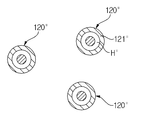
- FIG. 5 is a view showing one nozzle body cross section for forming a plurality of hollow fiber membrane in the apparatus for manufacturing a hollow fiber membrane bundle according to the present invention.
- FIG. 6 is a view showing a plurality of nozzle body cross section for forming a plurality of hollow fiber membrane in the apparatus for manufacturing a hollow fiber membrane bundle according to the present invention.
- FIG. 7 is a flowchart illustrating a manufacturing process of the hollow fiber membrane bundle according to FIG. 2.
- FIG. 8 is a partial view of an apparatus and process for manufacturing the hollow fiber membrane bundle according to the second embodiment of the present invention.
- FIG. 9 is a cross-sectional view illustrating the doped yarn taken along the arrow line B-B in FIG. 8.
- FIG. 10 is a view showing an apparatus and a process for dissolving and removing a support cable of a doped bundle wound up and cut by the winding roll of FIG. 8.
- FIG. 11 is a flowchart illustrating a manufacturing process of a hollow fiber membrane bundle according to FIGS. 8 and 10.
- the hollow fiber membrane bundle 10 of the present invention forms a bundle between the plurality of hollow fiber membranes 11 while forming a fluid flow path and a plurality of yarns 12 serving as spacers.
- the plurality of hollow fiber membranes 11 are arranged in one direction at intervals from each other, the plurality of yarns 12 are disposed in the spaces formed between the hollow fiber membranes 11, arranged in parallel with the array direction of the hollow fiber membranes Can be. In some cases, the hollow fiber membrane 11 and a part of the yarn 12 may contact each other.
- the hollow fiber membrane 11 is made of polyvinylidene fluoride (PVDF), polyacrylonitrile, polyacrylonitrile copolymer, polysulfone, sulfonated polysulfone, polyethersulfone , Cellulose acetate, cellulose triacetate, polymethyl methacrylate or a mixture thereof.
- PVDF polyvinylidene fluoride
- Yarn 12 is a mono-filament or multi-filament selected from at least one selected from the group consisting of polyvinylidene fluoride, polycarbonate, polystyrene, polyester, polyolefin, polyamide, polymethylmethacrylate, polyvinyl chloride, and fiberglass Or a mixture of mono-filament and multi-filament.
- the yarn 12 may be ATY (Air Textured Yarn) manufactured by the ATY method (air injection weaving method), or DTY (Draw Textured Yarn) manufactured by the DTY method.
- the ATY method is a method in which continuous filament yarns are exposed to compressed air streams so that each filament forms a plurality of loops and crimps.ATY manufactured by the ATY method forms a loop, so that the stretchability is low and the tension is reduced. The bulkiness does not decrease, and it functions as a fuzz on the surface of the yarn, and contains air to give a soft touch.
- DTY process is a method of twisting the thread and setting it again to partially inflate it, and DTY manufactured by DTY process does not feel smooth and cold unlike general chemical fiber and is soft and wide as natural fiber. Feel the texture.
- the ATY and the DTY are arranged to have refractions and bends, not straight lines, and since twisting, fine hairs, and irregularities are formed on the yarn surface, a predetermined space may be formed around the yarn. Even if the hollow fiber membrane 11 and the yarn 12 are arranged or contacted at a narrow interval due to the surrounding space, sufficient space is secured between the plurality of hollow fiber membranes 11 so that the fluid moves outside the hollow fiber membrane 11. It is easy.
- the yarn manufactured by other methods to form twists, fine hairs, irregularities, etc. on the surface of the yarn can also secure a space between the plurality of hollow fiber membranes 11 through the surrounding space. .
- the hollow fiber membrane 11 and the yarn 12 are preferably mixed at a ratio of 1 to 600 yarns per 100 hollow fiber membranes. It is preferable that the outer diameter of a hollow fiber membrane is 300-2000 m. It is preferable that the outer diameter of a yarn is 0.01-3. If the hollow fiber membrane is densely arranged, the flow of fluid will not be smooth. If the hollow fiber membrane is loose, the fluid may be biased to one side. Therefore, the mixing ratio and size of the hollow fiber membrane and yarn should be appropriate.
- the yarn 12 arranged between the hollow fiber membranes 11 forms a space between the hollow fiber membranes, forms a flow path of the fluid, and uniformly distributes the fluid to maximize the use efficiency of the hollow fiber membranes to produce a module.
- FIG. 2 is an apparatus and a process diagram for manufacturing the hollow fiber membrane bundle according to the first embodiment of the present invention
- Figure 3 is a detailed view showing the nozzle of Figure 2
- Figure 4 is a hollow fiber membrane of the AA line in FIG. It is sectional drawing
- FIG. 7 is a flowchart which shows the manufacturing process of the hollow fiber membrane bundle shown in FIG.
- the hollow fiber membrane bundle is manufactured by a spinning step S110, a solidification step S120, a yarn injection step S130, a cleaning step S140, and a winding step S150.
- the hollow fiber membrane 11 and the yarn 12 are shown to be manufactured as bundles, but a plurality of hollow fiber membranes 11 are formed at once and a plurality of hollow fiber membranes 11 are disposed between the plurality of hollow fiber membranes 11.
- Yarn 12 is introduced to produce one bundle 10 as shown in FIG. 1.
- a nozzle 120 ' having a plurality of radial holes H' having a ring cross-sectional shape is used in one nozzle body 121 ', or
- a plurality of nozzles 120 " each having a radial hole H " having a ring cross section is formed in each nozzle body 121 ".
- the spinning step (S110) is a step of forming the hollow fiber membrane 11 in which the hollow S is formed by supplying and spinning the spinning stock solution F to the nozzle 120 in the spinning stock tank 110.
- the spinning stock solution (F) consists of a polymer, an additive and a solvent
- the polymer may be polyvinylidene fluoride (PVDF), polyacrylonitrile, polyacrylonitrile copolymer, polysulfone, sulfonated poly Sulfonated polysulfone, polyethersulfone, cellulose acetate, cellulose triacetate, polymethyl methacrylate, and mixtures thereof.
- the additive may be composed of a group consisting of water, methyl alcohol, ethyl alcohol, ethylene glycol, polyethylene glycol, polypropylene glycol, glycerin, polyvinylpyrrolidone (PVP), and mixtures thereof.
- the solvent is N-methyl-2-pyrrolidone (NMP: N-methyl-2-pyrrolidone), dimethyl formamide (DMF: dimethyl formamide), dimethyl acetamide (DMAc: dimethyl acetamide), chloroform, Tetrahydrofuran (tetrahhydrofuran) and mixtures thereof.
- NMP N-methyl-2-pyrrolidone
- DMF dimethyl formamide
- DMAc dimethyl acetamide
- chloroform Tetrahydrofuran (tetrahhydrofuran) and mixtures thereof.
- the nozzle 120 has a plurality of spinning holes (H) having a ring cross-sectional shape in the nozzle body 121, and the spinning solution (F) is spun through the spinning holes (H) to form a hollow (S) therein. Form a desert (11). Spinning stock solution (F) is spun at 30 to maintain a viscosity of 40 ⁇ 70 as the range of 30,000cps to 60,000cps.
- the solidification step (S120) is a step of solidifying the plurality of hollow fiber membranes 11 formed in the spinning step (S110) in the solidification tank 130 at a temperature of 30 to 50, and a guide roll 131 installed inside the solidification tank 130. Guided through. The plurality of solidified hollow fiber membranes 11 are spun together with the yarns 12 on the plywood roll 150 via the guide roll R11.
- Yarn feeding step (S130) is a step of injecting the yarn into the yarn roll 150 from the bobbin 140 wound yarn, a plurality of yarns 12 between the plurality of hollow fiber membranes 11 guided to the yarn roll 150. ) Is a step of forming a bundle 10 through.
- the cleaning step (S140) is a step of cleaning the bundle 10 formed by plying through the plywood roll 150 and guided by guide rolls 161 and 162 installed in the cleaning tank 160.
- Winding step (S150) is a step in which the cleaned bundle 10 is guided by the guide roll (R12) is wound on the winding roll (170). The bundle 10 wound on the take-up roll 170 is cut to a certain length and moved to a module building facility for use.
- a plurality of yarns 12 is introduced between the plurality of hollow fiber membranes 11 to form a bundle 10
- the feeding step S130 may be performed, and after the yarn feeding step S130, a winding step S150 may be manufactured to wind the bundle 10.
- the method of manufacturing the hollow fiber membrane bundle according to the embodiment of the present invention, by manufacturing a bundle by adding a yarn during the production of the hollow fiber membrane, there is an effect of reducing the manufacturing equipment and simplifying the manufacturing process.
- FIG. 8 is a partial view of the apparatus and process for manufacturing the hollow fiber membrane bundle according to the second embodiment of the present invention
- Figure 9 is a cross-sectional view showing the doping yarn according to the arrow BB in Figure 8
- Figure 10 is a view of FIG.
- FIG. 11 is a view illustrating an apparatus and a process for dissolving and removing a support cable of a doped bundle unwound and cut from a take-up roll
- FIG. 11 is a flowchart illustrating a manufacturing process of a hollow fiber membrane bundle according to FIGS. 8 and 10.
- a plurality of doping yarns 21 are prepared by doping the radiation source solution F on the outer surfaces of the plurality of support cables C, and then a plurality of doping yarns.
- a support cable C inside the doped yarn 21 of the doped bundle 20 cut to a predetermined length by manufacturing and winding the doped bundle 20 by mixing the yarn 21 and the plurality of yarns 22. It is a method to dissolve and remove.
- the manufacturing step according to the manufacturing method of the hollow fiber membrane bundle according to the second embodiment of the invention is the support cable supply step (S200), spinning step (S210), solidification step (S220), and the yarn injection step ( S230, the cleaning step (S240), the winding step (S250), the cutting step (S260), and the support cable melting step (S270).
- Support cable supply step (S200) is a step of supplying the support cable (C) to the nozzle 220 in the support cable supply (280).
- the support cable (C) is a core cable made of polyvinyl alcohol (PVA) plasticized with a plasticizer of 5 to 20% by weight.
- Spinning step (S210) is a step of forming a plurality of doping yarn 21 by doping the outer surface of the support cable (C) by supplying and spinning the spinning stock solution (F) to the nozzle 220 in the spinning stock solution tank (210) . Since the spinning solution F is the same as the first embodiment, a detailed description thereof will be omitted.
- the nozzle 220 is formed with a plurality of spinning holes in the nozzle body, the radiation doping solution (F) is radiated through the space between the support cable (C) inserted through the spinning hole is doped yarn 21 Achieve.
- Spinning stock solution (F) is doped by maintaining the viscosity at 30 to 40 to 70 in the range of 30,000cps to 60,000cps at 30.
- Solidification step (S220) is a step of solidifying a plurality of doping yarn 21 formed in the spinning step (S210) in the coagulation tank 230 of 30 ⁇ 50 temperature, guide roll 231 installed inside the coagulation tank 230 Guided through.
- the plurality of solidified doped yarns 21 are spun together with the yarns 22 in the plywood roll 250 via the guide roll R21.
- Yarn feeding step (S230) is a step of injecting the yarn into the yarn roll 250 in the bobbin 240 wound yarn, a plurality of yarns 22 between the plurality of doping yarns 21 guided to the yarn roll 250. ) To form the doped bundle 20.
- the cleaning step (S240) is a step of cleaning the doped bundle 20 formed by being spun through the weaving roll 250, and is guided by guide rolls 261 and 262 installed in the cleaning tank 260.
- Winding step (S250) is a step in which the cleaned doped bundle 20 is guided by the guide roll (R22) is wound on the take-up roll 270.
- the support cable C in the cut doped bundle 20 is transferred to the cable dissolution tank 291.
- the hollow fiber membrane bundle is completed by performing a support cable dissolution step (S270) of supplying hot water of 60 to 80 to the cable dissolution tank 291 until the doping bundle 20 is locked.
- the hollow fiber membrane bundle 20 ' is transferred from the cable melt tank 291 to the further cleaning tank 292.
- the hollow fiber membrane bundles 20 ′ are diluted with a dilute aqueous solution of 0.1 to 0.5% NaOCl of 20 to 80, preferably 40 to 60, in a horizontal additional cleaning tank 292.
- a dilute aqueous solution of 0.1 to 0.5% NaOCl of 20 to 80, preferably 40 to 60, in a horizontal additional cleaning tank 292.
- Treatment to remove PVA and other contaminants remaining in the pores and inner diameter of the hollow fiber membrane is recycled through the pump 293 and the pipe for a predetermined time and then discharged through the discharge pipe.
- the hollow fiber membrane bundles with an internal diameter free of residual PVA and other contaminants that block the pores of the hollow fiber membranes are transferred to the module construction facility.
- the winding step (S250) of winding up the doped bundle 20 after the yarn injection step (S230) and the wound doping bundle 20 may be unwinded to perform the cutting step (S260).
- the hollow fiber membrane humidification module manufactured using the hollow fiber membrane bundle (applied yarn) according to the first embodiment of the present invention and the hollow fiber membrane humidification module manufactured using the conventional hollow fiber membrane bundle (non-applied yarn) of the humidification performance
- the effect of the present invention will be described as an example of the change experiment.
- the hollow fiber membrane humidification module without yarn is placed inside a cylindrical housing (60 mm in diameter and 350 mm in length) by using 1400 polysulfone hollow fiber membranes (outer diameter 800um, inner diameter 600um) as one hollow fiber membrane bundle, and forming potting parts at both ends of the housing. It was manufactured by covering the housing at both ends.
- Yarn-applied hollow fiber membrane humidification module is a cylindrical housing (diameter) by arranging 1400 yarns (general yarn, ATY yarn, DTY yarn) between 1400 polysulfone hollow fiber membranes (outer diameter 800um, inner diameter 600um). 60 mm, length 350 mm), and the pot was formed on both ends of the housing, and then the cover was placed on both ends of the housing.
- 150sLPM of dry air is introduced into the inside and outside of the hollow fiber membrane humidification module, and the outside of the hollow fiber membrane is fixed at 70 degrees Celsius and 90% humidity, and the inside of the hollow fiber membrane is fixed at 50 degrees Celsius and 10% humidity.
- Gas humidification was performed.
- the humidification performance was measured in terms of dew point by measuring the temperature and humidity at the point where the air flowing inside the hollow fiber membrane is humidified. The measurement results are shown in Table 1 below.
- the dew point is a measure of the humidification performance, and the higher the dew point at which the air is humidified, the better the humidification performance.
- Approach Dewpoint Temperature is one of the methods of expressing humidification performance (difference between dew point of air flowing into shell and dew point of humidified air).
- the humidification performance is different depending on the role of the spacer (yarn).
- the yarn having a better role as the spacer shows that the humid air outside the hollow fiber membrane uniformly surrounds the hollow fiber membrane, so that the humidification performance is high.
- Higher humidification performance than ATY and DTY yarns means that the spacers can do better.
- the ATY yarn and the DTY yarn improve the humidification performance when applied to the humidifier by making the role of the spacer more efficient than the general yarn.
- the humidification performance is improved compared to the case where the yarn is not applied.
Landscapes
- Chemical & Material Sciences (AREA)
- Chemical Kinetics & Catalysis (AREA)
- Engineering & Computer Science (AREA)
- Manufacturing & Machinery (AREA)
- Mechanical Engineering (AREA)
- Textile Engineering (AREA)
- Dispersion Chemistry (AREA)
- Separation Using Semi-Permeable Membranes (AREA)
Abstract
본 발명은 중공사막의 사용효율을 높이는 중공사막 번들 및 그 제조방법에 관한 것이다. 본 발명의 중공사막 번들은 복수의 중공사막 사이에는 유체의 유로를 형성하는 한편 스페이서 역할을 하는 복수의 원사가 배치되어 번들을 이룬다. 본 발명의 중공사막 번들의 제조방법은 노즐에 방사 원액을 공급하고 방사하여 복수의 중공사막을 형성하는 방사 단계와, 방사 단계에서 형성된 복수의 중공사막을 응고시키는 응고 단계와, 복수의 중공사막 사이에 복수의 원사를 투입하여 번들을 형성하는 원사투입 단계를 포함한다. 본 발명에 의하면, 중공사막 사이에 유체의 유로를 형성하여 유체의 분포를 균일하게 하여 중공사막의 사용효율을 극대화하여 모듈로 제작할 시에 성능을 향상하고, 중공사막 제조할 시에 원사를 투입하여 번들을 제조함으로서 제조 설비를 줄이고 제조 공정을 간단하고 용이하게 하는 효과가 있다.
Description
본 발명은 중공사막 번들 및 그 제조방법에 관한 것으로서, 보다 상세하게는 중공사막의 사용효율을 높이는 중공사막 번들 및 그 제조방법에 관한 것이다.
일반적으로 중공사막은 동일한 부피의 다른 막에 비해 막 표면적이 크고 모듈화하기 쉬운 장점 때문에 한외 여과막을 중심으로 그 응용이 활발히 진행되고 있다. 중공사막은 하수 종말처리, 정화조에서 고액분리, 산업폐수에서의 부유물질 제거, 하천수의 여과, 공업용수의 여과, 수영장물의 여과 및 연료전지용 가습기에 이용되고 있다.
연료전지용 가습기에 사용되는 선택적 투과막은 모듈을 형성할 경우 단위 체적당 투과 면적이 큰 중공사막이 바람직하다. 즉, 중공사막을 이용하여 가습기를 제조할 경우 접촉 표면적이 넓은 중공사막의 고집적화가 가능하여 소용량으로도 연료 전지의 가습이 충분히 이루어질 수 있고, 저가 소재의 사용이 가능하며, 연료 전지에서 고온으로 배출되는 미반응 가스에 포함된 수분과 열을 회수하여 가습기를 통해 재사용할 수 있다는 이점을 갖는다.
중공사막의 재질로는 셀룰로오스계 수지, 폴리아미드계 수지, 폴리비닐계 수지, 폴리아크릴계 수지 및 폴리올레핀계 수지 등이 사용된다.
중공사막 번들은 모두 동일한 통상의 방향으로 서로 인접하게 배열된 중공사막의 다발이다. 중공사막 모듈은 통상적으로 포팅(potting)에 의해 중공사막의 양끝이 헤더나 케이스 또는 하우징에 고정된 중공사막의 다발이다. 하나의 중공사막 번들은 하나의 중공사막 모듈을 형성할 수도 있고, 복수의 중공사막 번들이 하나의 중공사막 모듈을 형성할 수도 있다.
중공사막을 이용한 모듈의 경우 복수개의 중공사막을 100% 활용하기가 어렵다. 따라서 다양한 방법을 통하여 중공사막의 사용효율을 높이기 위한 기술들이 제안되어 있다.
일본공개특허 제2004-006100호 및 일본공개특허 제2009-285648호는 복수의 중공사막이 별도의 원사에 의해 묶여지거나 커버링되어 번들을 이루고, 일본공개특허 제2008-119657호는 복수의 중공사막을 재직하여 중공사막 편직물을 형성한다. 한편, 일본공개특허 제2012-005987호는 중공사막으로 모듈을 형성할 때에 중공사막 사이의 간격을 유지하기 위해 포팅부의 중공사막 사이에 개재물을 구비하는 구조이다.
그런데 이와 같은 종래 기술은 중공사막의 사용효율이 낮고 특히 유체가 기체인 경우는 그 사용효율이 더욱 낮다는 문제점이 있었다. 또한 중공사막 번들을 제조하기 위한 설비 등으로 인해 중공사막 번들을 제조하기가 쉽지 않다는 문제점이 있었다.
[선행기술문헌]
(특허문헌 1) 일본공개특허 제2004-006100호(공개일 : 2004.01.08.)
(특허문헌 2) 일본공개특허 제2009-285648호(공개일 : 2009.12.10.)
(특허문헌 3) 일본공개특허 제2008-119657호(공개일 : 2008.05.29.)
(특허문헌 4) 일본공개특허 제2012-005987호(공개일 : 2012.01.12.)
본 발명의 목적은 중공사막 사이에 유체의 유로를 형성하여 유체의 분포를 균일하게 하여 중공사막의 사용효율을 극대화하는 중공사막 번들을 제공하는 데 있다.
본 발명의 다른 목적은 중공사막 제조할 시에 원사를 투입하여 번들을 제조함으로서 제조를 용이하게 하는 중공사막 번들의 제조방법을 제공하는 데 있다.
본 발명에 따른 중공사막 번들은 복수의 중공사막 사이에는 유체의 유로를 형성하는 한편 스페이서 역할을 하는 복수의 원사가 배치되어 번들을 이루고 있다.
복수개의 중공사막은 일 방향으로 배열되며, 상기 복수의 원사는 중공사막의 배열 방향과 나란하게 배치될 수 있다.
중공사막은 PVDF(polyvinylidene fluoride), 폴리아크릴로나이트릴(polyacrylonitril), 폴리아크릴로나이트릴 공중합체, 폴리술폰(polysulfone), 술폰화폴리술폰(sulfonated polysulfone), 폴리에테르술폰(polyethersulfone), 셀룰로즈 아세테이트(cellulose acetate), 셀룰로즈트리아세테이트(cellulose triacetate), 폴리메틸메타아크릴레이트(polymethyl methacrylate) 또는 이들의 혼합물로 구성된 군으로 구성될 수 있다.
원사는 폴리불화비닐리덴, 폴리카보네이트, 폴리스타이렌, 폴리에스테로, 폴리올레핀, 폴리아마이드, 폴리메틸메타아크릴레이트, 폴리염화비닐 및 유리섬유로 구성된 구성에서 하나 이상 선택된 모노-필라멘트이거나 멀티-필라멘트이거나 모노-필라멘트와 멀티-필라멘트가 혼합된 구성일 수 있다. 원사는 ATY 공법으로 제조된 ATY사 또는 DTY 공법으로 사용된 DTY사가 사용된다.
중공사막과 원사는 중공사막 100개당 원사 1 ~ 600개의 비율로 혼합되어 번들을 이룬다.
중공사막의 외경은 300 ~ 2000 μm인 것이 바람직하다. 원사의 외경은 0.01 ~ 3㎜인 것이 바람직하다.
본 발명에 따른 중공사막 번들의 제조방법은 노즐에 방사 원액을 공급하고 방사하여 복수의 중공사막을 형성하는 방사 단계와, 방사 단계에서 형성된 복수의 중공사막을 응고시키는 응고 단계와, 복수의 중공사막 사이에 복수의 원사를 투입하여 번들을 형성하는 원사투입 단계를 포함한다.
원사투입 단계 후에 번들을 세정하는 세정 단계와, 세정 단계에서 세정된 번들을 권취하는 권취 단계를 추가로 포함한다. 응고 단계 후에는 복수의 중공사막을 세정한 후 복수의 중공사막 사이에 복수의 원사를 투입하여 번들을 형성하는 원사투입 단계를 행하고, 원사투입 단계 후에 번들을 권취하는 권취 단계를 포함할 수도 있다.
본 발명에 따른 중공사막 번들의 제조방법은 노즐에 지지케이블을 공급하는 지지케이블 공급단계와, 노즐에 방사 원액을 공급하고 방사하여 지지케이블의 외면에 도핑하여 복수의 도핑사를 형성하는 방사 단계와, 방사 단계에서 형성된 복수의 도핑사를 응고시키는 응고 단계와, 복수의 도핑사 사이에 복수의 원사를 투입하여 도핑 번들을 형성하는 원사투입 단계와, 도핑 번들을 일정한 길이로 절단하는 절단 단계와, 절단된 도핑 번들 내의 지지케이블을 용해하여 제거하는 지지케이블 용해단계를 포함할 수도 있다.
원사투입 단계 후에 도핑 번들을 세정하는 세정 단계와, 세정 단계에서 세정된 도핑 번들을 권취하는 권취 단계와, 권취된 도핑 번들을 권출하여 절단 단계를 행할 수도 있다. 응고 단계 후에 복수의 도핑사를 세정한 후 복수의 도핑사 사이에 복수의 원사를 투입하여 도핑 번들을 형성하는 원사투입 단계를 행하고, 원사투입 단계 후에 도핑 번들을 권취하는 권취 단계와, 권취된 도핑 번들을 권출하여 절단 단계를 행할 수도 있다.
본 발명에 의한 중공사막 번들 및 그 제조방법에 의하면, 중공사막 사이에 유체의 유로를 형성하여 유체의 분포를 균일하게 하여 중공사막의 사용효율을 극대화하여 모듈로 제작할 시에 성능을 향상하는 효과가 있다.
또한, 중공사막 제조할 시에 원사를 투입하여 번들을 제조함으로써 제조 설비를 줄이고 제조 공정을 간단하고 용이하게 하는 효과가 있다.
도 1은 본 발명에 따라 제조된 중공사막 번들의 단면도이다.
도 2은 본 발명의 제1 실시예에 따른 중공사막 번들을 제조하는 장치 및 공정도이다.
도 3는 도 2의 노즐을 나타내는 상세도이다.
도 4은 도 3에서 화살표 A-A선에 따른 중공사막의 단면도이다.
도 5는 본 발명에 따른 중공사막 번들을 제조하는 장치에서 복수의 중공사막을 형성하기 위한 하나의 노즐본체 단면을 나타내는 도면이다.
도 6은 본 발명에 따른 중공사막 번들을 제조하는 장치에서 복수의 중공사막을 형성하기 위한 복수의 노즐본체 단면을 나타내는 도면이다.
도 7은 도 2에 따른 중공사막 번들의 제조공정을 나타내는 플로우 차트이다.
도 8은 본 발명의 제2실시예에 따른 중공사막 번들을 제조하는 장치 및 공정의 일부 도면이다.
도 9는 도 8에서 화살표 B-B선에 따른 도핑사를 나타내는 단면도이다.
도 10은 도 8의 권취롤에서 권출되어 절단된 도핑 번들의 지지케이블을 용해시켜 제거하는 장치 및 공정을 나타내는 도면이다.
도 11은 도 8 및 도 10에 따른 중공사막 번들의 제조공정을 나타내는 플로우 차트이다.
이하, 본 발명이 속하는 기술 분야에서 통상의 지식을 가진 자가 용이하게 실시할 수 있도록 본 발명의 실시예에 대하여 상세히 설명한다. 그러나 본 발명은 여러 가지 상이한 형태로 구현될 수 있으며 여기에서 설명하는 실시예에 한정되지 않는다.
도 1은 본 발명에 따라 제조된 중공사막 번들의 단면도이다. 도시한 바와 같이 본 발명의 중공사막 번들(10)은 복수의 중공사막(11) 사이에는 유체의 유로를 형성하는 한편 스페이서 역할을 하는 복수의 원사(12)가 배치되어 번들을 이루고 있다.
복수개의 중공사막들(11)은 서로 간격을 두고 일 방향으로 배열되고, 복수의 원사(12)는 중공사막들(11) 사이에 형성된 공간들에 배치되며, 중공사막의 배열 방향과 나란하게 배치될 수 있다. 또한 경우에 따라서는 중공사막(11)과 원사(12)의 일부가 접할 수도 있다.
중공사막(11)은 PVDF(polyvinylidene fluoride), 폴리아크릴로나이트릴(polyacrylonitril), 폴리아크릴로나이트릴 공중합체, 폴리술폰(polysulfone), 술폰화폴리술폰(sulfonated polysulfone), 폴리에테르술폰(polyethersulfone), 셀룰로즈 아세테이트(cellulose acetate), 셀룰로즈트리아세테이트(cellulose triacetate), 폴리메틸메타아크릴레이트(polymethyl methacrylate) 또는 이들의 혼합물로 구성된 군으로 구성된다.
원사(12)는 폴리불화비닐리덴, 폴리카보네이트, 폴리스타이렌, 폴리에스테로, 폴리올레핀, 폴리아마이드, 폴리메틸메타아크릴레이트, 폴리염화비닐 및 유리섬유로 구성된 구성에서 하나 이상 선택된 모노-필라멘트이거나 멀티-필라멘트이거나 모노-필라멘트와 멀티-필라멘트가 혼합된 실이다. 원사(12)는 ATY 공법(공기 분사식 직물법)으로 제조된 ATY(Air Textured Yarn), 또는 DTY 공법으로 제조된 DTY(Draw Textured Yarn)가 사용될 수 있다.
ATY 공법은 연속적인 필라멘트사를 압축공기 기류에 노출시켜 각각의 필라멘트가 다수의 루프와 크림프를 형성하게 하는 방법으로서, ATY 공법으로 제조된 ATY는 루프를 형성하고 있으므로, 신장성이 낮고 장력에 의해 벌키성이 감소하지 않으며, 방적사 표면의 잔털과 같은 기능을 하며 공기를 함유하고 있어서 부드러운 촉감을 준다.
DTY 공법은 실을 꼬았다가 다시 풀면서 세팅하여 부분적으로 부풀어 오르게 하는 방법으로서, DTY 공법으로 제조된 DTY는 사의 표면이 일반 화학섬유와는 달리 매끈하고 차거운 느낌이 들지 않고 천연섬유처럼 부드럽고 폭닥한 질감을 느끼게 한다.
이러한 ATY나 DTY는 일방향으로 배열했을 때, 일직선이 아닌 굴절과 굴곡을 갖도록 배치되며, 또한 원사 표면에 꼬임, 잔털, 요철 등이 형성되기 때문에, 원사 주변에 소정 공간이 형성될 수 있다. 이와 같은 주변 공간으로 인해 중공사막(11)과 원사(12)가 좁은 간격으로 배열되거나 접하더라도, 복수의 중공사막들(11) 사이로 충분한 공간이 확보되어 중공사막(11) 외부로 유체가 이동하기 용이하다. 이러한 ATY나 DTY 이외에도 굴절과 굴곡을 가지며, 원사 표면에 꼬임, 잔털, 요철 등이 형성하도록 다른 공법으로 제조된 원사 역시 주변 공간으로 통해 복수의 중공사막들(11) 사이에 공간을 확보할 수 있다.
중공사막(11)과 원사(12)는 중공사막 100개당 원사 1 ~ 600개의 비율로 혼합되는 것이 바람직하다. 중공사막의 외경은 300 ~ 2000 m인 것이 바람직하고. 원사의 외경은 0.01 ~ 3인 것이 바람직하다. 중공사막이 빽빽하게 배치되면 유체의 흐름이 원활하지 못하고 중공사막이 느슨하게 배치되면 유체가 한쪽으로 치우칠 우려가 있으므로 중공사막과 원사의 혼합비율 및 크기는 적절해야 한다.
중공사막(11) 사이에 배열된 원사(12)는 중공사막 사이 사이에 공간을 형성하는 한편 유체의 유로를 형성하고 유체의 분포를 균일하게 하여 중공사막의 사용효율을 극대화하여 모듈로 제작할 시에 성능을 향상시킨다.
도 2은 본 발명의 제1 실시예에 따른 중공사막 번들을 제조하는 장치 및 공정도이고, 도 3는 도 2의 노즐을 나타내는 상세도이며, 도 4은 도 3에서 화살표 A-A선에 따른 중공사막의 단면도이고, 도 7은 도 2에 따른 중공사막 번들의 제조공정을 나타내는 플로우 차트이다. 도시한 바와 같이 중공사막 번들은 방사 단계(S110)와, 응고 단계(S120)와, 원사투입 단계(S130)와, 세정 단계(S140)와, 권취 단계(S150)로 제조된다.
도 2에서는 하나의 중공사막(11)과 하나의 원사(12)로 번들을 제조하는 것으로 표시되어 있으나, 복수의 중공사막(11)이 한꺼번에 형성되고 복수의 중공사막(11) 사이 사이에 복수의 원사(12)가 투입되어 도 1에 도시한 바와 같은 하나의 번들(10)이 제조된다. 복수의 중공사막(11)이 제조되기 위해서는 도 5에 도시한 바와 같이 하나의 노즐 본체(121')에 고리 단면형태의 다수의 방사구멍(H')이 형성된 노즐(120')이 사용되거나, 도 6에 도시한 바와 같이 복수의 노즐 본체(121") 각각에 고리 단면 형태의 방사구멍(H")이 각각 형성된 복수의 노즐(120")이 사용된다.
방사 단계(S110)은 방사원액 탱크(110)에서 노즐(120)에 방사원액(F)을 공급하고 방사하여 내부에 중공(S)이 형성된 중공사막(11)을 형성하는 단계이다.
방사원액(F)은 폴리머, 첨가제 및 용매로 구성되며, 예컨대 폴리머는 PVDF(polyvinylidene fluoride), 폴리아크릴로나이트릴(polyacrylonitril), 폴리아크릴로나이트릴 공중합체, 폴리술폰(polysulfone), 술폰화폴리술폰(sulfonated polysulfone), 폴리에테르술폰(polyethersulfone), 셀룰로즈 아세테이트(cellulose acetate), 셀룰로즈트리아세테이트(cellulose triacetate), 폴리메틸메타아크릴레이트(polymethyl methacrylate) 및 이들의 혼합물로 구성된 군으로 구성될 수 있다. 또한, 첨가제는 물, 메틸알콜, 에틸알콜, 에틸렌글리콜, 폴리에틸렌글리콜, 폴리프로필렌글리콜, 글리세린, 폴리비닐피롤리돈(polyvinyl pyrrolidone, PVP)류 및 이들의 혼합물로 구성된 군으로 구성될 수 있다. 또한, 용매는 N-메틸-2-피롤리돈(NMP : N-methyl-2-pyrrolidone), 디메틸포름아미드(DMF:dimethyl formamide), 디메틸아세트아미드(DMAc:dimethyl acetamide), 클로로포름(chloroform), 테트라하이드로퓨란(tetrahhydrofuran) 및 이들의 혼합물로 구성된 군으로 구성될 수 있다.
노즐(120)은 노즐 본체(121)에 고리 단면형태의 다수의 방사구멍(H)이 형성되고, 방사원액(F)은 방사구멍(H)을 통해 방사되어 내부에 중공(S)이 형성된 중공사막(11)을 이룬다. 방사원액(F)은 30 에서 점도가 30,000cps 내지 60,000cps의 범위로서 40~70로 유지시켜 방사된다.
응고 단계(S120)는 방사 단계(S110)에서 형성된 복수의 중공사막(11)을 30 ~ 50 온도의 응고조(130)에서 응고시키는 단계로서, 응고조(130) 내부에 설치된 안내롤(131)을 통해 안내된다. 응고된 복수의 중공사막(11)은 안내롤(R11)을 거쳐 합사롤(150)에서 원사(12)와 합사된다.
원사투입 단계(S130)는 원사가 감긴 보빈(140)에서 합사롤(150)로 원사를 투입하는 단계로서, 합사롤(150)로 안내되는 복수의 중공사막(11) 사이에 복수의 원사(12)를 개재시켜 번들(10)을 형성하는 단계이다.
세정 단계(S140)는 합사롤(150)을 통해 합사되어 형성된 번들(10)을 세정하는 단계로서, 세정조(160) 내에 설치된 안내롤(161, 162)에 의해 안내된다. 권취 단계(S150)는 세정된 번들(10)이 안내롤(R12)에 의해 안내되어 권취롤(170)에 권취되는 단계이다. 권취롤(170)에 권취된 번들(10)은 일정한 길이로 절단되어 모듈 구축 설비로 이동되어 사용된다.
한편, 응고 단계(S120) 후에는 복수의 중공사막(11)을 세정한 후(S140), 복수의 중공사막(11) 사이에 복수의 원사(12)를 투입하여 번들(10)을 형성하는 원사투입 단계(S130)를 행하고, 원사투입 단계(S130) 후에 번들(10)을 권취하는 권취 단계(S150)로 제조될 수도 있다.
본 발명의 실시예에 의한 중공사막 번들의 제조방법에 의하면, 중공사막 제조할 시에 원사를 투입하여 번들을 제조함으로서 제조 설비를 줄이고 제조 공정을 간단하고 용이하게 하는 효과가 있다.
도 8은 본 발명의 제2실시예에 따른 중공사막 번들을 제조하는 장치 및 공정의 일부 도면이고, 도 9는 도 8에서 화살표 B-B선에 따른 도핑사를 나타내는 단면도이며, 도 10은 도 8의 권취롤에서 권출되어 절단된 도핑 번들의 지지케이블을 용해시켜 제거하는 장치 및 공정을 나타내는 도면이고, 도 11은 도 8 및 도 10에 따른 중공사막 번들의 제조공정을 나타내는 플로우 차트이다.
본 발명의 제2실시예에 따라 중공사막 번들을 제조하는 방법은 복수의 지지케이블(C)의 외면에 방사원액(F)을 도핑하여 복수의 도핑사(21)를 제조한 후, 복수의 도핑사(21)와 복수의 원사(22)를 혼합하여 도핑 번들(20)을 제조하고 권취한 다음, 일정 길이로 절단한 도핑 번들(20)의 도핑사(21) 내부에 있는 지지케이블(C)을 용해시켜 제거하는 방법이다. 도시한 바와 같이 발명의 제2실시예에 의한 중공사막 번들의 제조방법에 의한 제조 단계는 지지케이블 공급단계(S200)과, 방사 단계(S210)와, 응고 단계(S220)와, 원사투입 단계(S230)와, 세정 단계(S240)와, 권취 단계(S250)와, 절단 단계(S260)와, 지지케이블 용해단계(S270)로 이루어진다.
지지케이블 공급 단계(S200)는 지지케이블 공급기(280)에서 노즐(220)에 지지케이블(C)을 공급하는 단계이다. 지지케이블(C)은 5~20 중량%의 가소제로 가소화된 폴리비닐알콜(PVA)로 이루어진 코어 케이블이다.
방사 단계(S210)은 방사원액 탱크(210)에서 노즐(220)에 방사원액(F)을 공급하고 방사하여 지지케이블(C)의 외면에 도핑하여 복수의 도핑사(21)를 형성하는 단계이다. 방사원액(F)은 제1실시예와 동일하므로 자세한 설명은 생략한다. 노즐(220)은 노즐 본체에 복수의 방사구멍이 형성되고, 방사구멍을 통해 삽입된 지지케이블(C)의 사이의 공간을 통해 방사원액(F)이 방사되어 도핑됨에 따라 도핑사(21)을 이룬다. 방사원액(F)은 30 에서 점도가 30,000cps 내지 60,000cps의 범위로서 40~70로 유지시켜 도핑된다.
응고 단계(S220)는 방사 단계(S210)에서 형성된 복수의 도핑사(21)을 30 ~ 50 온도의 응고조(230)에서 응고시키는 단계로서, 응고조(230) 내부에 설치된 안내롤(231)을 통해 안내된다. 응고된 복수의 도핑사(21)는 안내롤(R21)을 거쳐 합사롤(250)에서 원사(22)와 합사된다.
원사투입 단계(S230)는 원사가 감긴 보빈(240)에서 합사롤(250)로 원사를 투입하는 단계로서, 합사롤(250)로 안내되는 복수의 도핑사(21) 사이에 복수의 원사(22)를 개재시켜 도핑 번들(20)을 형성하는 단계이다.
세정 단계(S240)는 합사롤(250)을 통해 합사되어 형성된 도핑 번들(20)을 세정하는 단계로서, 세정조(260) 내에 설치된 안내롤(261, 262)에 의해 안내된다. 권취 단계(S250)는 세정된 도핑 번들(20)이 안내롤(R22)에 의해 안내되어 권취롤(270)에 권취되는 단계이다.
권취롤(270)에 권취된 도핑 번들(20)을 권출시켜 일정한 길이로 절단하는 절단 단계(S260)을 거쳐, 절단된 도핑 번들(20) 내의 지지케이블(C)을 케이블 용해 탱크(291)에 수직으로 적절한 방법으로 걸어 둔 후, 도핑 번들(20)이 잠길 때까지 케이블 용해 탱크(291) 상부로 60~80의 열수를 공급하는 지지케이블 용해 단계(S270)을 행하여 중공사막 번들을 완성한다.
PVA(폴리비닐알콜)의 밀도는 약 1.33이기 때문에 가소화된 PVA가 용해됨에 따라 용해된 PVA는 중공사막 번들(도핑 번들)의 내외부를 통해 케이블 용해 탱크(291) 아래 쪽으로 내려오게 된다. PVA로 오염된 하층부위의 오염수는 케이블 용해 탱크(291)의 아래에 모인 후 제거된다.
케이블 용해 탱크(291)에서의 PVA의 농도가 약 0.5% 미만인 경우, 중공사막 번들(20')은 케이블 용해 탱크(291)로부터 추가 세정 탱크(292)로 옮겨진다. 이 단계까지 여전히중공사막의 많은 기공이 막혀 있게 되어, 중공사막 번들(20')은 수평한 추가 세정 탱크(292)내에서20 내지 80 바람직하게는 40 내지 60의 0.1 내지 0.5% NaOCl 묽은 수용액으로 처리하여중공사막의 기공 및 내경 속에 잔류된PVA 및 기타 오염물을 제거한다. 상기 수용액은 펌프(293)및배관을 통해 일정시간동안재순환된 후배출관을 통하여배출된다. 이 단계를 지나게 되면 중공사막의 기공을 막히게 하는 잔류 PVA 및 기타 오염물이 존재하지 않는 내경을 지니는중공사막 번들이 모듈구축 설비로 이송된다.
한편, 응고 단계(S220) 후에 복수의 도핑사(21)를 세정한 후 복수의 도핑사(21) 사이에 복수의 원사(22)를 투입하여 도핑 번들(20)을 형성하는 원사투입 단계(S230)를 행하고, 원사투입 단계(S230) 후에 도핑 번들(20)을 권취하는 권취 단계(S250)와, 권취된 도핑 번들(20)을 권출하여 절단 단계(S260)를 행할 수도 있다.
이하에서는 본 발명의 제1실시예에 따른 중공사막 번들(원사 적용)을 이용하여 제조된 중공사막 가습 모듈과, 종래 중공사막 번들(원사 미적용)을 이용하여 제조된 중공사막 가습 모듈로 가습성능의 변화를 실험한 예로 본 발명의 효과를 설명한다.
[제조 실시예: 중공사막 가습 모듈의 제조]
원사 미적용 중공사막 가습 모듈은 폴리설폰 중공사막(외경 800um, 내경 600um) 1400개를 하나의 중공사막 번들로 하여 원통형 하우징(직경 60mm, 길이 350mm) 내부에 배치시키고 하우징 양단에 포팅부를 형성한 후, 하우징 양단부에 커버를 씌워 제조되었다.
원사 적용 중공사막 가습 모듈은 폴리설폰 중공사막(외경 800um, 내경 600um) 1400개 사이에 원사(일반사, ATY사, DTY사) 1400개를 각각 배치하여 하나의 중공사막 번들로 하여 원통형 하우징(직경 60mm, 길이 350mm) 내부에 배치시키고 하우징 양단에 포팅부를 형성한 후, 하우징 양단부에 커버를 씌워 제조되었다.
[실험예 : 제조된 중공사막 가습 모듈의 성능 측정]
중공사막 가습 모듈의 중공사막 내부와 외부에 각각 150sLPM의 건조공기를 유입하고 중공사막 외부는 섭씨 70도, 습도 90%로 고정하고, 중공사막 내부는 섭씨 50도, 습도 10%로 고정하여 기체-기체 가습을 실시하였다. 가습 성능은 중공사막 내부를 흐르는 공기가 가습되어 나오는 지점의 온도와 습도를 측정하여 노점(Dew Point)으로 환산하여 측정하였다. 그 측정 결과는 하기 표 1에 나타내었다. 노점은 가습 성능을 나타내는 척도로서 공기가 가습되어 나오는 지점의 노점이 높을수록 가습성능이 뛰어나다고 할 수 있다.
표 1
| 원사미적용 | 일반 원사적용 | ATY 원사적용 | DTY 원사적용 | |
| 가습성능(ADT, 섭씨온도) | 11 | 10 | 8 | 8.3 |
상기 표 1을 참조하면, 동일한 중공사막에 원사(스페이서)의 종류만 변경하여 실험을 진행해 보았을 때 중공사막 외부의 습한 공기(Shell)의 균일한 정도에 따라 가습 성능의 차이가 나타남을 알 수 있고, 가습성능이 높은 ATY 원사 및 DTY 원사는 독특한 원사 표면으로 인하여 일반 원사에 비하여 중공사막 사이에 공간을 잘 형성시킬 수 있다. 즉, ATY 원사 및 DTY 원사는 일반 원사보다 스페이서로서의 성능이 우수하다.(공기가 균일하게 퍼져 모든 중공사막이 다 쓰여야 가습성능이 높게 나타남)
표 1에서 ADT(Approach Dewpoint Temperature)는 가습성능을 나타내는 방식의 하나이다.(쉘에 유입된 공기의 노점과 가습되어져 나온 공기의 노점의 차이)
동일한 중공사막에서 스페이서(원사)의 역할에 따라 가습성능이 다르게 나타나게 되는데, 스페이서의 역할을 더 잘하는 원사일수록 중공사막 외부의 습한 공기가 균일하게 중공사막 외부를 감싸주어 가습성능이 높게 나타나게 된다. ATY 원사 및 DTY 원사가 일반 원사에 비해 가습성능이 높다는 의미는 스페이서의 역할을 더 잘할 수 있다는 의미이다.
표 1에서 나타난 바와 같이 ATY 원사 및 DTY 원사는 일반 원사에 비해 스페이서의 역할을 더 효율적으로 함으로써 가습기에 적용시 가습성능이 향상된다. 또한 원사를 적용한 경우가 원사를 적용하지 않은 경우에 비해 가습성능이 향상된다.
이상에서 본 발명의 바람직한 실시예에 대하여 상세하게 설명하였지만 본 발명의 권리범위는 이에 한정되는 것은 아니고 다음의 청구범위에서 정의하고 있는 본 발명의 기본 개념을 이용한 당업자의 여러 변형 및 개량 형태 또한 본 발명의 권리범위에 속하는 것이다.
[부호의 설명]
10: 중공사막 번들 11: 중공사막
12, 22: 원사 20: 도핑 번들
21: 도핑사
110, 210: 방사원액 탱크 120, 220: 노즐
130, 230: 응고조 140, 240: 보빈
150, 250: 합사롤 160, 260: 세정조
170, 270: 권취롤 280: 지지케이블 공급기
291: 케이블 용해 탱크 292: 추가 세정 탱크
C: 지지 케이블 F: 방사 원액
H: 방사 구멍 S: 중공
Claims (13)
- 복수의 중공사막으로 이루어진 중공사막 번들에 있어서,상기 복수의 중공사막 사이에는 유체의 유로를 형성하는 한편 스페이서 역할을 하는 복수의 원사가 배치되어 번들을 이루고 있으며,상기 원사는 ATY 공법으로 제조된 ATY사 또는 DTY 공법으로 사용된 DTY사가 사용되는 것을 특징으로 하는 중공사막 번들.
- 청구항 1에 있어서,상기 복수개의 중공사막은 일 방향으로 배열되며, 상기 복수의 원사는 중공사막의 배열 방향과 나란하게 배치되는 것을 특징으로 하는 중공사막 번들.
- 청구항 1에 있어서,상기 중공사막은 PVDF(polyvinylidene fluoride), 폴리아크릴로나이트릴(polyacrylonitril), 폴리아크릴로나이트릴 공중합체, 폴리술폰(polysulfone), 술폰화폴리술폰(sulfonated polysulfone), 폴리에테르술폰(polyethersulfone), 셀룰로즈 아세테이트(cellulose acetate), 셀룰로즈트리아세테이트(cellulose triacetate), 폴리메틸메타아크릴레이트(polymethyl methacrylate) 또는 이들의 혼합물로 구성된 군으로 이루어지는 것을 특징으로 하는 중공사막 번들.
- 청구항 1에 있어서,상기 원사는 폴리불화비닐리덴, 폴리카보네이트, 폴리스타이렌, 폴리에스테로, 폴리올레핀, 폴리아마이드, 폴리메틸메타아크릴레이트, 폴리염화비닐 및 유리섬유로 구성된 구성에서 하나이상 선택된 모노-필라멘트이거나 멀티-필라멘트이거나 모노-필라멘트와 멀티-필라멘트가 혼합된 것을 특징으로 하는 중공사막 번들.
- 청구항 1에 있어서,상기 중공사막과 상기 원사는 중공사막 100개당 원사 1 ~ 600개의 비율로 혼합되어 번들을 이루는 것을 특징으로 하는 중공사막 번들.
- 청구항 1에 있어서,상기 중공사막의 외경은 300 ~ 2000 μm인 것을 특징으로 하는 중공사막 번들.
- 청구항 1에 있어서,상기 원사의 외경은 0.01 ~ 3㎜인 것을 특징으로 하는 중공사막 번들.
- 청구항 1의 중공사막 번들을 제조하는 방법으로서,노즐에 방사 원액을 공급하고 방사하여 복수의 중공사막을 형성하는 방사 단계와,상기 방사 단계에서 형성된 상기 복수의 중공사막을 응고시키는 응고 단계와,상기 복수의 중공사막 사이에 복수의 원사를 투입하여 번들을 형성하는 원사투입 단계를 포함하는 것을 특징으로 하는 중공사막 번들의 제조방법.
- 청구항 8에 있어서,상기 원사투입 단계 후에 상기 번들을 세정하는 세정 단계와,상기 세정 단계에서 세정된 번들을 권취하는 권취 단계를 추가로 포함하는 것을 특징으로 하는 중공사막 번들의 제조방법.
- 청구항 8에 있어서,상기 응고 단계 후에는 상기 복수의 중공사막을 세정한 후 상기 복수의 중공사막 사이에 복수의 원사를 투입하여 상기 번들을 형성하는 상기 원사투입 단계를 행하고,상기 원사투입 단계 후에 상기 번들을 권취하는 권취 단계를 행하는 것을 특징으로 하는 중공사막 번들의 제조방법.
- 청구항 1의 중공사막 번들을 제조하는 방법으로서,노즐에 지지케이블을 공급하는 지지케이블 공급단계와,상기 노즐에 방사 원액을 공급하고 방사하여 상기 지지케이블의 외면에 도핑하여 복수의 도핑사를 형성하는 방사 단계와,상기 방사 단계에서 형성된 복수의 도핑사를 응고시키는 응고 단계와,상기 복수의 도핑사 사이에 복수의 원사를 투입하여 도핑 번들을 형성하는 원사투입 단계와,상기 도핑 번들을 일정한 길이로 절단하는 절단 단계와,상기 절단된 도핑 번들 내의 상기 지지케이블을 용해하여 제거하는 지지케이블 용해단계를 포함하는 것을 특징으로 하는 중공사막 번들의 제조방법.
- 청구항 11에 있어서,상기 원사투입 단계 후에 상기 도핑 번들을 세정하는 세정 단계와, 상기 세정 단계에서 세정된 도핑 번들을 권취하는 권취 단계를 행하고,권취된 상기 도핑 번들을 권출하여 상기 절단 단계를 행하는 것을 특징으로 하는 중공사막 번들의 제조방법.
- 청구항 11에 있어서,상기 응고 단계 후에 상기 복수의 도핑사를 세정한 후 상기 복수의 도핑사 사이에 복수의 원사를 투입하여 상기 도핑 번들을 형성하는 상기 원사투입 단계를 행하고,상기 원사투입 단계 후에 상기 도핑 번들을 권취하는 권취 단계를 행한 다음,상기 권취된 도핑 번들을 권출하여 상기 절단 단계를 행하는 것을 특징으로 하는 중공사막 번들의 제조방법.
Priority Applications (4)
| Application Number | Priority Date | Filing Date | Title |
|---|---|---|---|
| JP2017542116A JP6516852B2 (ja) | 2015-02-12 | 2016-02-12 | 中空糸膜バンドル及びその製造方法 |
| US15/550,145 US20180028979A1 (en) | 2015-02-12 | 2016-02-12 | Bundle of hollow fiber membranes and manufacturing method therefor |
| CN201680009908.6A CN107206324A (zh) | 2015-02-12 | 2016-02-12 | 中空纤维膜束及其制造方法 |
| EP16749498.8A EP3257572A4 (en) | 2015-02-12 | 2016-02-12 | Bundle of hollow fiber membranes and manufacturing method therefor |
Applications Claiming Priority (2)
| Application Number | Priority Date | Filing Date | Title |
|---|---|---|---|
| KR10-2015-0021601 | 2015-02-12 | ||
| KR1020150021601A KR20160099304A (ko) | 2015-02-12 | 2015-02-12 | 중공사막 번들 및 그 제조방법 |
Publications (1)
| Publication Number | Publication Date |
|---|---|
| WO2016129958A1 true WO2016129958A1 (ko) | 2016-08-18 |
Family
ID=56615300
Family Applications (1)
| Application Number | Title | Priority Date | Filing Date |
|---|---|---|---|
| PCT/KR2016/001448 Ceased WO2016129958A1 (ko) | 2015-02-12 | 2016-02-12 | 중공사막 번들 및 그 제조방법 |
Country Status (6)
| Country | Link |
|---|---|
| US (1) | US20180028979A1 (ko) |
| EP (1) | EP3257572A4 (ko) |
| JP (1) | JP6516852B2 (ko) |
| KR (1) | KR20160099304A (ko) |
| CN (1) | CN107206324A (ko) |
| WO (1) | WO2016129958A1 (ko) |
Cited By (1)
| Publication number | Priority date | Publication date | Assignee | Title |
|---|---|---|---|---|
| CN108745000A (zh) * | 2018-05-29 | 2018-11-06 | 佛山市盟发净水科技有限公司 | 一种抗菌中空纤维纳滤膜的制备方法 |
Families Citing this family (8)
| Publication number | Priority date | Publication date | Assignee | Title |
|---|---|---|---|---|
| KR102090322B1 (ko) | 2018-10-30 | 2020-03-17 | (주)대동정공 | 중공사 합사장치 |
| US12048898B2 (en) | 2019-02-28 | 2024-07-30 | Toyobo Mc Corporation | Hollow fiber membrane and method for producing hollow fiber membrane |
| KR102147980B1 (ko) | 2019-10-22 | 2020-08-25 | (주)대동정공 | 스페이서사 함유 중공사 번들, 이를 제작하기 위한 장치 및 방법 |
| BR112022009694A2 (pt) * | 2019-12-17 | 2022-08-09 | Pirelli | Processo e aparelho para fabricar um cabo de reforço metálico para pneus para rodas de veículos |
| CN111111452B (zh) * | 2020-01-03 | 2022-08-30 | 天津碧水源膜材料有限公司 | 中空纤维帘式膜元件的处理方法和中空纤维帘式膜组件 |
| CN112451774B (zh) * | 2020-12-03 | 2025-10-28 | 山东威高血液净化制品股份有限公司 | 一种吸附增强型透析器 |
| JP7776541B2 (ja) * | 2021-09-01 | 2025-11-26 | コーロン インダストリーズ インク | 中空糸膜カートリッジ |
| CN114082021A (zh) * | 2021-12-03 | 2022-02-25 | 山东威高血液净化制品股份有限公司 | 一种透析液流动改善型透析器 |
Citations (5)
| Publication number | Priority date | Publication date | Assignee | Title |
|---|---|---|---|---|
| JP2000325762A (ja) * | 1999-05-18 | 2000-11-28 | Mitsubishi Rayon Co Ltd | 分離膜成形体およびこれを用いた中空糸膜モジュール |
| KR20040008935A (ko) * | 2002-07-19 | 2004-01-31 | 주식회사 파라 | 모노-필라멘트를 포함하는 보강용 지지체를 가지는기체분리 및 수처리용 외압식 중공사막, 그 제조방법 및제조장치 |
| KR20080048791A (ko) * | 2006-11-29 | 2008-06-03 | 윤호성 | 중공사막 제조방법 |
| KR20110078829A (ko) * | 2009-12-31 | 2011-07-07 | 한국에너지기술연구원 | 무기질 중공사 번들 및 그 제조방법 |
| KR20130064813A (ko) * | 2010-09-29 | 2013-06-18 | 미쯔비시 레이온 가부시끼가이샤 | 폴리올레핀 복합 중공사막 및 그 제조 방법, 그리고 중공사막 모듈 |
Family Cites Families (19)
| Publication number | Priority date | Publication date | Assignee | Title |
|---|---|---|---|---|
| DE123476C (ko) * | 1960-09-19 | |||
| US4293418A (en) * | 1979-03-28 | 1981-10-06 | Toray Industries, Inc. | Fluid separation apparatus |
| DE3805414C1 (ko) * | 1988-02-22 | 1989-09-07 | Secon Gesellschaft Fuer Separations- Und Concentrationstechnik Mbh, 3402 Dransfeld, De | |
| US5198110A (en) * | 1990-07-02 | 1993-03-30 | Asahi Medical Co., Ltd. | Bundle of permselective hollow fibers and a fluid separator containing the same |
| EP0732141B1 (de) * | 1995-03-11 | 2000-03-22 | Akzo Nobel N.V. | Hohlfadenbündel sowie Stoff- und/oder Wärmetauscher |
| JP3684676B2 (ja) * | 1995-06-30 | 2005-08-17 | 東レ株式会社 | ポリスルホン系中空糸型人工腎臓の製造方法および人工腎臓 |
| US5779897A (en) * | 1996-11-08 | 1998-07-14 | Permea, Inc. | Hollow fiber membrane device with inert filaments randomly distributed in the inter-fiber voids |
| KR100352450B1 (ko) * | 2001-04-12 | 2002-09-11 | 주식회사 사이버알닷컴 | 복수의 매장이 공동사용 가능한 무인 신용카드 승인 방법및 시스템, 그리고 매장별 거래내역 조회 방법 |
| KR100485620B1 (ko) * | 2002-01-15 | 2005-04-27 | 주식회사 파라 | 보강용 지지체를 가진 중공사막, 그 제조방법 및 이를제조하기 위한 방사구금 |
| JP4211290B2 (ja) | 2002-05-31 | 2009-01-21 | Nok株式会社 | 燃料電池の加湿装置 |
| JP2008119657A (ja) | 2006-11-15 | 2008-05-29 | Mitsubishi Rayon Eng Co Ltd | 中空糸膜モジュール |
| JP4468485B2 (ja) * | 2007-12-04 | 2010-05-26 | パナソニック株式会社 | 燃料電池システム |
| JP5412938B2 (ja) | 2008-04-28 | 2014-02-12 | 東レ株式会社 | 中空糸モジュールおよびその製造方法 |
| CN102481524B (zh) * | 2009-08-21 | 2014-06-18 | 东丽株式会社 | 水蒸气透过性膜、中空纱膜和中空纱膜组件 |
| JP2012005987A (ja) | 2010-06-28 | 2012-01-12 | Aisan Industry Co Ltd | 中空糸分離膜モジュール |
| US8529814B2 (en) * | 2010-12-15 | 2013-09-10 | General Electric Company | Supported hollow fiber membrane |
| JP2014522313A (ja) * | 2011-06-06 | 2014-09-04 | ダウ コーニング コーポレーション | ポリエーテル及びシリカ質充填剤を含有するシリコーン組成物から誘導される膜 |
| JP2015037767A (ja) * | 2012-10-31 | 2015-02-26 | Nok株式会社 | 中空糸膜モジュール用ケース |
| JP2014117651A (ja) * | 2012-12-17 | 2014-06-30 | Nok Corp | 加湿膜ユニット |
-
2015
- 2015-02-12 KR KR1020150021601A patent/KR20160099304A/ko not_active Ceased
-
2016
- 2016-02-12 WO PCT/KR2016/001448 patent/WO2016129958A1/ko not_active Ceased
- 2016-02-12 JP JP2017542116A patent/JP6516852B2/ja active Active
- 2016-02-12 EP EP16749498.8A patent/EP3257572A4/en not_active Withdrawn
- 2016-02-12 US US15/550,145 patent/US20180028979A1/en not_active Abandoned
- 2016-02-12 CN CN201680009908.6A patent/CN107206324A/zh active Pending
Patent Citations (5)
| Publication number | Priority date | Publication date | Assignee | Title |
|---|---|---|---|---|
| JP2000325762A (ja) * | 1999-05-18 | 2000-11-28 | Mitsubishi Rayon Co Ltd | 分離膜成形体およびこれを用いた中空糸膜モジュール |
| KR20040008935A (ko) * | 2002-07-19 | 2004-01-31 | 주식회사 파라 | 모노-필라멘트를 포함하는 보강용 지지체를 가지는기체분리 및 수처리용 외압식 중공사막, 그 제조방법 및제조장치 |
| KR20080048791A (ko) * | 2006-11-29 | 2008-06-03 | 윤호성 | 중공사막 제조방법 |
| KR20110078829A (ko) * | 2009-12-31 | 2011-07-07 | 한국에너지기술연구원 | 무기질 중공사 번들 및 그 제조방법 |
| KR20130064813A (ko) * | 2010-09-29 | 2013-06-18 | 미쯔비시 레이온 가부시끼가이샤 | 폴리올레핀 복합 중공사막 및 그 제조 방법, 그리고 중공사막 모듈 |
Cited By (1)
| Publication number | Priority date | Publication date | Assignee | Title |
|---|---|---|---|---|
| CN108745000A (zh) * | 2018-05-29 | 2018-11-06 | 佛山市盟发净水科技有限公司 | 一种抗菌中空纤维纳滤膜的制备方法 |
Also Published As
| Publication number | Publication date |
|---|---|
| CN107206324A (zh) | 2017-09-26 |
| EP3257572A4 (en) | 2018-08-01 |
| KR20160099304A (ko) | 2016-08-22 |
| JP6516852B2 (ja) | 2019-05-22 |
| JP2018505053A (ja) | 2018-02-22 |
| US20180028979A1 (en) | 2018-02-01 |
| EP3257572A1 (en) | 2017-12-20 |
Similar Documents
| Publication | Publication Date | Title |
|---|---|---|
| WO2016129958A1 (ko) | 중공사막 번들 및 그 제조방법 | |
| AU2013378841B2 (en) | Membrane assembly for supporting a biofilm | |
| WO2012177058A2 (en) | Pressurized hollow fiber membrane module | |
| CN104117289B (zh) | 一种增强复合支撑中空纤维膜及其制备方法 | |
| WO2010120100A9 (en) | Composite hollow fiber membrane and method for manufacturing the same | |
| WO2017116117A1 (ko) | 라이오셀 섬유 및 이의 제조방법 | |
| WO2011037354A2 (ko) | 불소계 중공사막 및 그 제조 방법 | |
| WO2013073828A1 (ko) | 친수성 폴리불화비닐리덴계 중공사 분리막 및 이의 제조방법 | |
| CN102527250B (zh) | 一种中空纤维膜及其制造方法 | |
| WO2022145781A1 (ko) | 중공사막 및 그 제조방법 | |
| US20150283517A1 (en) | Hollow porous membrane | |
| WO2021085766A1 (ko) | 나권형 분리막 모듈 및 이의 제조방법 | |
| CN102068923A (zh) | 一种聚偏氟乙烯中空纤维膜的制造方法 | |
| WO2012074222A9 (ko) | 셀룰로오스계 수지를 이용한 수처리용 중공사막의 제조방법 | |
| KR101726537B1 (ko) | 중공사막 및 그 제조방법 | |
| WO2015102292A1 (ko) | 복합 중공사막 및 그 제조방법 | |
| WO2014175281A1 (ja) | 繊維強化多孔質中空糸膜の製造方法 | |
| CN114340769A (zh) | 流体分离用碳膜组件 | |
| CN109092082B (zh) | 一种高湿度中空纤维滤膜丝浇筑方法 | |
| KR100844043B1 (ko) | 중공사막 제조방법 | |
| JP7562983B2 (ja) | 多孔質中空糸膜の製造方法 | |
| CN212800618U (zh) | 原丝凝固成纤装置 | |
| WO2020130674A1 (ko) | 여과막 형성용 조성물, 이를 이용한 여과막 제조방법 및 여과막 | |
| WO2024232733A1 (ko) | 가습기용 중공사막, 이의 제조방법, 및 상기 중공사막을 포함하는 가습기 | |
| JPH028047B2 (ko) |
Legal Events
| Date | Code | Title | Description |
|---|---|---|---|
| 121 | Ep: the epo has been informed by wipo that ep was designated in this application |
Ref document number: 16749498 Country of ref document: EP Kind code of ref document: A1 |
|
| REEP | Request for entry into the european phase |
Ref document number: 2016749498 Country of ref document: EP |
|
| ENP | Entry into the national phase |
Ref document number: 2017542116 Country of ref document: JP Kind code of ref document: A |
|
| NENP | Non-entry into the national phase |
Ref country code: DE |