WO2016132466A1 - 空気調和システム - Google Patents
空気調和システム Download PDFInfo
- Publication number
- WO2016132466A1 WO2016132466A1 PCT/JP2015/054357 JP2015054357W WO2016132466A1 WO 2016132466 A1 WO2016132466 A1 WO 2016132466A1 JP 2015054357 W JP2015054357 W JP 2015054357W WO 2016132466 A1 WO2016132466 A1 WO 2016132466A1
- Authority
- WO
- WIPO (PCT)
- Prior art keywords
- temperature
- compressor
- signal
- thermostat
- inverter
- Prior art date
- Legal status (The legal status is an assumption and is not a legal conclusion. Google has not performed a legal analysis and makes no representation as to the accuracy of the status listed.)
- Ceased
Links
Images


Classifications
-
- F—MECHANICAL ENGINEERING; LIGHTING; HEATING; WEAPONS; BLASTING
- F24—HEATING; RANGES; VENTILATING
- F24F—AIR-CONDITIONING; AIR-HUMIDIFICATION; VENTILATION; USE OF AIR CURRENTS FOR SCREENING
- F24F11/00—Control or safety arrangements
- F24F11/89—Arrangement or mounting of control or safety devices
-
- F—MECHANICAL ENGINEERING; LIGHTING; HEATING; WEAPONS; BLASTING
- F25—REFRIGERATION OR COOLING; COMBINED HEATING AND REFRIGERATION SYSTEMS; HEAT PUMP SYSTEMS; MANUFACTURE OR STORAGE OF ICE; LIQUEFACTION SOLIDIFICATION OF GASES
- F25B—REFRIGERATION MACHINES, PLANTS OR SYSTEMS; COMBINED HEATING AND REFRIGERATION SYSTEMS; HEAT PUMP SYSTEMS
- F25B13/00—Compression machines, plants or systems, with reversible cycle
-
- F—MECHANICAL ENGINEERING; LIGHTING; HEATING; WEAPONS; BLASTING
- F24—HEATING; RANGES; VENTILATING
- F24F—AIR-CONDITIONING; AIR-HUMIDIFICATION; VENTILATION; USE OF AIR CURRENTS FOR SCREENING
- F24F11/00—Control or safety arrangements
- F24F11/30—Control or safety arrangements for purposes related to the operation of the system, e.g. for safety or monitoring
-
- F—MECHANICAL ENGINEERING; LIGHTING; HEATING; WEAPONS; BLASTING
- F24—HEATING; RANGES; VENTILATING
- F24F—AIR-CONDITIONING; AIR-HUMIDIFICATION; VENTILATION; USE OF AIR CURRENTS FOR SCREENING
- F24F11/00—Control or safety arrangements
- F24F11/62—Control or safety arrangements characterised by the type of control or by internal processing, e.g. using fuzzy logic, adaptive control or estimation of values
-
- F—MECHANICAL ENGINEERING; LIGHTING; HEATING; WEAPONS; BLASTING
- F24—HEATING; RANGES; VENTILATING
- F24F—AIR-CONDITIONING; AIR-HUMIDIFICATION; VENTILATION; USE OF AIR CURRENTS FOR SCREENING
- F24F2110/00—Control inputs relating to air properties
- F24F2110/10—Temperature
-
- F—MECHANICAL ENGINEERING; LIGHTING; HEATING; WEAPONS; BLASTING
- F25—REFRIGERATION OR COOLING; COMBINED HEATING AND REFRIGERATION SYSTEMS; HEAT PUMP SYSTEMS; MANUFACTURE OR STORAGE OF ICE; LIQUEFACTION SOLIDIFICATION OF GASES
- F25B—REFRIGERATION MACHINES, PLANTS OR SYSTEMS; COMBINED HEATING AND REFRIGERATION SYSTEMS; HEAT PUMP SYSTEMS
- F25B49/00—Arrangement or mounting of control or safety devices
- F25B49/02—Arrangement or mounting of control or safety devices for compression type machines, plants or systems
- F25B49/022—Compressor control arrangements
-
- F—MECHANICAL ENGINEERING; LIGHTING; HEATING; WEAPONS; BLASTING
- F24—HEATING; RANGES; VENTILATING
- F24F—AIR-CONDITIONING; AIR-HUMIDIFICATION; VENTILATION; USE OF AIR CURRENTS FOR SCREENING
- F24F11/00—Control or safety arrangements
- F24F11/62—Control or safety arrangements characterised by the type of control or by internal processing, e.g. using fuzzy logic, adaptive control or estimation of values
- F24F11/63—Electronic processing
-
- F—MECHANICAL ENGINEERING; LIGHTING; HEATING; WEAPONS; BLASTING
- F25—REFRIGERATION OR COOLING; COMBINED HEATING AND REFRIGERATION SYSTEMS; HEAT PUMP SYSTEMS; MANUFACTURE OR STORAGE OF ICE; LIQUEFACTION SOLIDIFICATION OF GASES
- F25B—REFRIGERATION MACHINES, PLANTS OR SYSTEMS; COMBINED HEATING AND REFRIGERATION SYSTEMS; HEAT PUMP SYSTEMS
- F25B2600/00—Control issues
- F25B2600/02—Compressor control
- F25B2600/021—Inverters therefor
-
- F—MECHANICAL ENGINEERING; LIGHTING; HEATING; WEAPONS; BLASTING
- F25—REFRIGERATION OR COOLING; COMBINED HEATING AND REFRIGERATION SYSTEMS; HEAT PUMP SYSTEMS; MANUFACTURE OR STORAGE OF ICE; LIQUEFACTION SOLIDIFICATION OF GASES
- F25B—REFRIGERATION MACHINES, PLANTS OR SYSTEMS; COMBINED HEATING AND REFRIGERATION SYSTEMS; HEAT PUMP SYSTEMS
- F25B2600/00—Control issues
- F25B2600/02—Compressor control
- F25B2600/025—Compressor control by controlling speed
- F25B2600/0253—Compressor control by controlling speed with variable speed
-
- F—MECHANICAL ENGINEERING; LIGHTING; HEATING; WEAPONS; BLASTING
- F25—REFRIGERATION OR COOLING; COMBINED HEATING AND REFRIGERATION SYSTEMS; HEAT PUMP SYSTEMS; MANUFACTURE OR STORAGE OF ICE; LIQUEFACTION SOLIDIFICATION OF GASES
- F25B—REFRIGERATION MACHINES, PLANTS OR SYSTEMS; COMBINED HEATING AND REFRIGERATION SYSTEMS; HEAT PUMP SYSTEMS
- F25B2700/00—Sensing or detecting of parameters; Sensors therefor
- F25B2700/21—Temperatures
- F25B2700/2104—Temperatures of an indoor room or compartment
-
- F—MECHANICAL ENGINEERING; LIGHTING; HEATING; WEAPONS; BLASTING
- F25—REFRIGERATION OR COOLING; COMBINED HEATING AND REFRIGERATION SYSTEMS; HEAT PUMP SYSTEMS; MANUFACTURE OR STORAGE OF ICE; LIQUEFACTION SOLIDIFICATION OF GASES
- F25B—REFRIGERATION MACHINES, PLANTS OR SYSTEMS; COMBINED HEATING AND REFRIGERATION SYSTEMS; HEAT PUMP SYSTEMS
- F25B2700/00—Sensing or detecting of parameters; Sensors therefor
- F25B2700/21—Temperatures
- F25B2700/2106—Temperatures of fresh outdoor air
-
- Y—GENERAL TAGGING OF NEW TECHNOLOGICAL DEVELOPMENTS; GENERAL TAGGING OF CROSS-SECTIONAL TECHNOLOGIES SPANNING OVER SEVERAL SECTIONS OF THE IPC; TECHNICAL SUBJECTS COVERED BY FORMER USPC CROSS-REFERENCE ART COLLECTIONS [XRACs] AND DIGESTS
- Y02—TECHNOLOGIES OR APPLICATIONS FOR MITIGATION OR ADAPTATION AGAINST CLIMATE CHANGE
- Y02B—CLIMATE CHANGE MITIGATION TECHNOLOGIES RELATED TO BUILDINGS, e.g. HOUSING, HOUSE APPLIANCES OR RELATED END-USER APPLICATIONS
- Y02B30/00—Energy efficient heating, ventilation or air conditioning [HVAC]
- Y02B30/70—Efficient control or regulation technologies, e.g. for control of refrigerant flow, motor or heating
Definitions
- the present invention relates to an air conditioning system.
- an air-conditioning system configured to inverter-control a compressor so that the indoor temperature approaches an optimum temperature.
- Such an air conditioning system is configured to control the operation of the compressor based on the room temperature, the blowing temperature, the suction pressure and the discharge pressure of the compressor, etc. after setting the set temperature. That is, the general air conditioning system is configured to detect at least one of the blowout temperature, the compressor suction pressure and the discharge pressure in addition to the room temperature, and these detection values are Operation control of the compressor is performed so as to approach a preset target value.
- the set temperature is set by remote control, and the set temperature, room temperature, blow-out temperature, compressor suction pressure and discharge pressure are signal processed in the control device of the air conditioning system. Thereafter, an inverter control signal is output from the control device to the compressor.
- a thermostat hereinafter referred to as a local thermostat
- the local thermostat is configured to detect a room temperature, compare the detected room temperature with a set temperature, and output a signal that instructs the controller to turn the compressor on or off according to the comparison result. ing.
- the local thermostat only transmits a compressor ON or OFF signal to a control device that controls the operation of the compressor. For this reason, the local thermostat frequently sends a compressor ON or OFF signal to bring the room temperature closer to the set temperature, and the compressor is repeatedly operated and stopped to increase the power consumption of the air conditioning system. There was a problem that. Further, since the compressor is repeatedly operated and stopped, there is a problem that it is difficult to keep the room temperature constant and the comfort is impaired.
- the present invention has been made to solve the above-described problems, and an object of the present invention is to obtain an air conditioning system capable of suppressing power consumption and maintaining a constant room temperature.
- An air conditioning system includes a refrigerant circuit in which a compressor, a heat source side heat exchanger, an expansion device, and a load side heat exchanger are sequentially connected via a pipe, an inverter that drives the compressor, and an indoor temperature
- An indoor temperature detector that detects a thermostat ON signal and a thermostat OFF signal, and a control device that controls the inverter according to the thermostat ON signal and the thermostat OFF signal.
- the controller estimates the indoor temperature as the set temperature, and the difference between the indoor temperature and the set temperature is within a certain range.
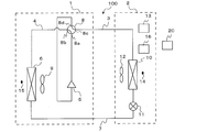
- FIG. 1 is a schematic circuit configuration diagram showing an example of a circuit configuration of the air-conditioning apparatus according to Embodiment 1 of the present invention.
- the air conditioning system 100 includes an outdoor unit 1 and an indoor unit 2, and the compressor 5 is controlled by a local thermostat 20.
- the outdoor unit 1 and the indoor unit 2 are connected by a refrigerant main pipe 3 and a refrigerant main pipe 7.
- a compressor 5, a switching valve 8 such as a four-way valve, and a heat source side heat exchanger 6 are connected and mounted via a refrigerant pipe 4.
- the outdoor unit 1 is equipped with a blower 9 and an outdoor temperature detector 15.
- the compressor 5 sucks in a low-temperature and low-pressure refrigerant and compresses the refrigerant into a high-temperature and high-pressure state, and is composed of, for example, an inverter compressor capable of capacity control.
- a blower 9 is provided in the vicinity of the heat source side heat exchanger 6, and the blower 9 blows air to the heat source side heat exchanger 6.
- the heat source side heat exchanger 6 functions as a condenser during cooling operation, functions as an evaporator during heating operation, and performs heat exchange between air supplied from a blower 9 such as a fan and a refrigerant, for example. is there.
- the switching valve 8 switches a refrigerant flow in a cooling operation mode, which will be described later, and a refrigerant flow in a heating operation mode.
- the outdoor temperature detector 15 is composed of, for example, a thermistor and detects the outdoor air temperature.
- the indoor unit 2 is equipped with a blower 12, a load side heat exchanger 10, a throttle device 11, a control device 13, an indoor temperature detector 14, and an inverter 16.
- the indoor unit 2 is connected to the outdoor unit 1 via the refrigerant main pipe 3 and the refrigerant main pipe 7 so that the refrigerant flows in or out.
- the compressor 5, the heat source side heat exchanger 6, the expansion device 11, and the load side heat exchanger 10 are sequentially connected via the pipes to constitute the refrigerant circuit of the air conditioning system 100.
- the load-side heat exchanger 10 performs heat exchange between air supplied from an air blower 12 such as a fan and a refrigerant, and generates heating air or cooling air to be supplied to an indoor space.
- the expansion device 11 has a function as a pressure reducing valve or an expansion valve, expands the refrigerant by depressurizing it, and is preferably constituted by a device whose opening degree can be variably controlled, for example, an electronic expansion valve.
- the indoor temperature detector 14 is composed of, for example, a thermistor, and detects the indoor air temperature.
- the control device 13 is constituted by, for example, a microcomputer, and reads indoor temperature information from the indoor temperature detector 14 and reads outdoor temperature information from the outdoor temperature detector 15. Further, the control device 13 controls the inverter 16 based on an instruction from the local thermostat 20 described later, and controls the output frequency of the compressor 5 and the rotational speed of the blower 9 of the heat source side heat exchanger 6. Further, the control device 13 controls the switching of the switching valve 8, the opening degree of the expansion device 11, and the like, and executes a cooling operation mode and a heating operation mode which will be described later. The inverter 16 drives the compressor 5 based on a command from the control device 13.
- the local thermostat 20 is a device in which the control function of the thermostat and the compressor 5 is added to the remote controller.
- the local thermostat 20 compares the room temperature detected by the thermostat with the set temperature. Then, an ON or OFF signal of the compressor 5 is transmitted to the control device 13 according to the comparison result.
- the control device 13 operates the compressor 5 when receiving an ON signal of the compressor 5 and stops the compressor 5 when receiving an OFF signal of the compressor 5.
- the operation of controlling or stopping the compressor 5 by the local thermostat 20 is referred to as local thermostat control.
- the control device 13 In the local thermostat control, since the local thermostat 20 does not transmit the information on the set temperature of the room temperature to the control device 13, the control device 13 cannot receive the magnitude information of the air conditioning load. For this reason, when the control device 13 receives the ON signal of the compressor 5, the control device 13 controls the compressor 5 at the maximum frequency operation (MAX-Hz operation), and the compressor 5 OFF signal. Can be executed only to control the compressor 5 to stop.
- the ON signal of the compressor 5 corresponds to the “thermostat ON signal” in the present invention.
- the OFF signal of the compressor 5 corresponds to the “thermostat OFF signal” in the present invention.
- FIG. 2 is a refrigerant circuit diagram illustrating a refrigerant flow when the air-conditioning apparatus according to Embodiment 1 of the present invention is in the cooling operation mode.
- the switching valve 8 in the cooling operation mode, the switching valve 8 is in a state where the first port 8a and the second port 8b communicate with each other, and the third port 8c and the fourth port 8d communicate with each other. It becomes. In this way, the refrigerant flows in the direction indicated by the solid arrow in FIG.
- the low-temperature and low-pressure refrigerant is compressed by the compressor 5 and discharged as a high-temperature and high-pressure gas refrigerant.
- the high-temperature and high-pressure gas refrigerant discharged from the compressor 5 flows into the heat source side heat exchanger 6 through the switching valve 8.
- the high-temperature high-pressure gas refrigerant that has flowed into the heat source side heat exchanger 6 condenses while dissipating heat to the outdoor air, and becomes high-pressure liquid refrigerant.
- the high-pressure liquid refrigerant that has flowed out of the heat source side heat exchanger 6 flows out of the outdoor unit 1, passes through the refrigerant main pipe 7, and flows into the indoor unit 2.
- the high-pressure liquid refrigerant that has flowed into the indoor unit 2 is reduced to a low-temperature and low-pressure two-phase refrigerant by the expansion device 11 and then flows into the load-side heat exchanger 10 that acts as an evaporator.
- the low-temperature and low-pressure two-phase refrigerant cools the room air by absorbing heat from the room air, and becomes a low-temperature and low-pressure gas refrigerant.
- the low-temperature and low-pressure gas refrigerant that has flowed out of the load-side heat exchanger 10 passes through the refrigerant main pipe 3 and flows into the outdoor unit 1.
- the refrigerant flowing into the outdoor unit 1 passes through the switching valve 8 and is sucked into the compressor 5.
- the cooling operation mode is performed by circulating the refrigerant in this way.
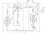
- FIG. 3 is a refrigerant circuit diagram illustrating a refrigerant flow when the air-conditioning apparatus according to Embodiment 1 of the present invention is in the heating operation mode.
- the switching valve 8 in the heating operation mode, the switching valve 8 is in a state where the first port 8a and the third port 8c communicate with each other, and the second port 8b and the fourth port 8d communicate with each other. It becomes. In this way, the refrigerant flows in the direction indicated by the solid arrow in FIG.
- the low-temperature and low-pressure refrigerant is compressed by the compressor 5 and discharged as a high-temperature and high-pressure gas refrigerant.
- the high-temperature and high-pressure gas refrigerant discharged from the compressor 5 flows into the indoor unit 2 through the refrigerant main pipe 3 via the switching valve 8.
- the high-temperature high-pressure gas refrigerant that has flowed into the indoor unit 2 radiates heat to the room air in the load-side heat exchanger 10, becomes high-pressure liquid refrigerant, and flows into the expansion device 11.
- the refrigerant flows out of the indoor unit 2, passes through the refrigerant main pipe 7, and flows into the outdoor unit 1.
- the low-temperature and low-pressure two-phase refrigerant that has flowed into the outdoor unit 1 becomes low-temperature and low-pressure gas refrigerant by absorbing heat from the outdoor air in the heat source side heat exchanger 6.
- the low-temperature and low-pressure gas refrigerant exiting the heat source side heat exchanger 6 passes through the switching valve 8 and is sucked into the compressor 5.
- heating operation mode is performed because a refrigerant
- coolant circulates.
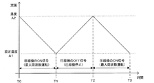
- FIG. 4 is a graph showing a change in room temperature in the conventional local thermostat control.
- the air conditioning system 100 has a cooling operation mode and a heating operation mode.
- local thermostat control of the air conditioning system 100 in the cooling operation mode will be described as an example.
- the vertical axis represents room temperature
- the horizontal axis represents time.
- a set temperature A 1 and a reference temperature A 2 for transmitting the ON signal of the compressor 5 are set.
- the control device 13 receives the ON signal of the compressor 5 from the local thermostat 20, and thus causes the compressor 5 to perform maximum frequency operation.
- the room temperature is lowered from A2 to the set temperature A1.
- the control device 13 stops the operation of the compressor 5 because it receives the OFF signal of the compressor 5 from the local thermostat 20.
- the room temperature is warmed by the outside air or the like, and increases from the set temperature A1 to A2.
- the control device 13 receives the ON signal of the compressor 5 from the local thermostat 20, and therefore causes the compressor 5 to perform maximum frequency operation.
- the operation of the compressor 5 causes the room temperature to drop from A2 to the set temperature A1.
- the room temperature rises to A2 in order to stop the compressor 5 after the room temperature reaches the set temperature A1. Therefore, the room temperature cannot be kept constant at the set temperature A1. Therefore, after reaching the set temperature A1, it is necessary to maintain the room temperature at the set temperature A1 by performing inverter control described later.
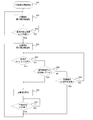
- FIG. 5 is a flowchart showing the control operation of the control device 13 during the local thermostat control of FIG.
- the control operation of the control device 13 will be described based on the steps of FIG. 5 with reference to FIG.
- Step S11 The control device 13 starts the operation of the compressor 5. Thereafter, the process proceeds to step S12.
- Step S12 The control device 13 receives the ON signal of the compressor 5 and causes the compressor 5 to perform the maximum frequency operation. Thereafter, the process proceeds to step S13.
- Step S13 The control device 13 determines whether the room temperature has reached the set temperature A1. If the room temperature reaches the set temperature A1, the process proceeds to step S14. Otherwise, the process proceeds to step S13.
- Step S14 The control device 13 receives the OFF signal of the compressor 5 and stops the operation of the compressor 5. Thereafter, the process proceeds to step S15.
- Step S15 The control device 13 determines whether the room temperature has reached A2. When the room temperature reaches A2, the process proceeds to step S12. Otherwise, the process proceeds to step S15.
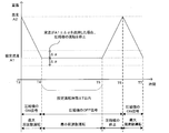
- FIG. 6 is a graph showing a room temperature change in the local thermostat control and the inverter control according to the first embodiment of the present invention.
- the air conditioning system 100 has a cooling operation mode and a heating operation mode.
- local thermostat control of the air conditioning system 100 in the cooling operation mode will be described as an example.
- the vertical axis of the graph represents room temperature and the horizontal axis represents time.
- the local thermostat 20 is set with a set temperature A1 and a temperature A2 for transmitting an ON signal of the compressor 5.
- the control device 13 receives the ON signal of the compressor 5 from the local thermostat 20, and therefore controls the inverter 16 to cause the compressor 5 to perform the maximum frequency operation.
- the room temperature is lowered from A2 to the set temperature A1.
- the control device 13 receives an OFF signal of the compressor 5 from the local thermostat 20. Then, simultaneously with the reception of the OFF signal, the control device 13 shifts from local thermostat control to inverter control, and continues inverter control until time T5. That is, the control device 13 controls the inverter 16 to output the output frequency of the compressor 5 so that the difference between the room temperature and the set temperature A1 is maintained within the reference range between the time T4 and the time T5. To control.
- the operation of the compressor 5 at this output frequency is referred to as minimum frequency operation (min-Hz operation).
- control device 13 cannot receive the set temperature A1 information from the local thermostat 20, but reads the indoor temperature information from the indoor temperature detector 14 and determines the indoor temperature when the OFF signal of the compressor 5 is received. Inverter control is performed by estimating the set temperature A1.
- the inverter control is shifted to the local thermostat control.
- the first condition is when the room temperature exceeds the allowable temperature difference ⁇ from the set temperature A1.
- the second condition is a case where the time during which the inverter control is performed exceeds the set operation time ⁇ T.
- the third condition is when an ON signal is transmitted from the local thermostat 20 to the control device 13.
- the allowable temperature difference ⁇ and the set operation time ⁇ T are stored in the control device 13 in advance.
- the control device 13 shifts from inverter control to local thermostat control.
- the control device 13 stops the compressor 5 when receiving the OFF signal of the compressor 5 after the transition of the local thermostat control, and operates the compressor 5 at the maximum frequency when receiving the ON signal of the compressor 5.
- Control to do the control device 13 receives the OFF signal of the compressor 5 from the local thermostat 20, and therefore controls the inverter 16 to stop the operation of the compressor 5.
- the room temperature rises from A1 to A2 due to the operation stop of the compressor 5, and the local thermostat 20 transmits an ON signal of the compressor 5 to the control device 13 at time T6 when the room temperature reaches A2.
- the control device 13 receives the ON signal of the compressor 5 from the local thermostat 20, and therefore controls the inverter 16 to perform the maximum frequency operation of the compressor 5. .
- the room temperature is lowered from A2 to A1.
- FIG. 7 is a flowchart showing the control operation of the control device 13 at the time of local thermostat control and inverter control of FIG.
- the control operation of the control device 13 will be described based on the steps of FIG. 7 with reference to FIG.
- Step S21 The control device 13 starts the operation of the compressor 5. Thereafter, the process proceeds to step S22.
- Step S22 The control device 13 receives the ON signal of the compressor 5 and causes the compressor 5 to perform the maximum frequency operation (start of local thermostat control). Thereafter, the process proceeds to step S23.
- Step S23 The control device 13 determines whether the room temperature has reached the set temperature A1. If the room temperature reaches the set temperature A1, the process proceeds to step S24. Otherwise, the process proceeds to step S23.
- Step S24 The control device 13 receives the OFF signal of the compressor 5 and performs the minimum frequency operation of the compressor 5 (start of inverter control). Thereafter, the process proceeds to step S25.
- Step S25 The control device 13 determines whether the room temperature is within the allowable temperature difference ⁇ with respect to the set temperature A1. When the room temperature is within the allowable temperature difference ⁇ with respect to the set temperature A1, the process proceeds to step S26. Otherwise, the process proceeds to step S28.
- Step S26 The control device 13 stops the operation of the compressor 5. Thereafter, the process proceeds to step S27.
- Step S27 The control device 13 determines whether the room temperature has reached A2. When the room temperature reaches A2, the process proceeds to step S22. Otherwise, the process proceeds to step S27.
- Step S28 The control device 13 determines whether the time during which the inverter 16 is being controlled has passed the set operation time ⁇ T. When the time during which the inverter 16 is controlled has passed the set operation time ⁇ T, the process proceeds to step S26. Otherwise, the process proceeds to step S29.
- Step S29 The control device 13 determines whether an ON signal is transmitted from the local thermostat 20 to the control device 13. When the ON signal is transmitted from the local thermostat 20 to the control device 13, the process proceeds to step S22. Otherwise, the process proceeds to step S25.
- the room temperature information read from the room temperature detector 14 is estimated as the set temperature A1, and the local thermostat control is shifted to the inverter control. By doing in this way, it can prevent that the operation
- the following three effects can be obtained by setting the three conditions for shifting from the inverter control described above to the local thermostat control.
- the first effect is that even when the room temperature deviates from the allowable temperature difference ⁇ with respect to the set temperature A1, the room temperature is quickly returned to the set temperature A1 by shifting from the inverter control to the local thermostat control. Can do.
- the second effect is that even if the set temperature A1 is changed by the local thermostat 20 during the inverter control, after the set operation time ⁇ T has elapsed, the process shifts to the local thermostat control.
- the air conditioning system 100 can be operated.
- the third effect is that when the control device 13 receives the ON signal of the compressor 5 during inverter control, the change of the set temperature A1 or the range of the allowable temperature difference ⁇ with respect to the set temperature A1 with respect to the set temperature A1. It is thought that it exceeded. For this reason, it can transfer to local thermostat control and control which makes room temperature close to preset temperature A1 can be performed.
- the local thermostat control and the inverter control in the cooling operation mode of the air conditioning system 100 have been described.
- the present invention is not limited to this, and the above control can be performed in the heating operation mode. Is possible.
- the air conditioning system 100 that performs both the cooling operation mode and the heating operation mode has been described.
- the present invention is not limited to this, and the air that performs only the cooling operation mode or only the heating operation mode.
- the above-described control can be performed for the harmony system 100 as well. The same applies to the second embodiment described later.
- Embodiment 2 Since the basic configuration of the air-conditioning system 100 according to the second embodiment is the same as that of the air-conditioning system 100 according to the first embodiment, hereinafter, the second embodiment will be described with a focus on differences from the first embodiment. explain. The difference between the first embodiment and the second embodiment is that the set operation time ⁇ T for performing inverter control is variable.
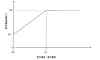
- FIG. 8 is a graph showing the relationship between the difference between the outdoor temperature and the room temperature according to Embodiment 2 of the present invention and the set operation time.
- the air conditioning system 100 has a cooling operation mode and a heating operation mode.
- setting of the set operation time ⁇ T in the cooling operation mode will be described as an example.
- the vertical axis of the graph represents the set operation time ⁇ T
- the horizontal axis represents the difference between the outdoor temperature and the indoor temperature.
- the influence of the outdoor temperature on the indoor temperature can be suppressed by setting the setting operation time ⁇ T for performing the inverter control to be longer as the difference between the outdoor temperature and the indoor temperature is larger.
Landscapes
- Engineering & Computer Science (AREA)
- Mechanical Engineering (AREA)
- General Engineering & Computer Science (AREA)
- Chemical & Material Sciences (AREA)
- Combustion & Propulsion (AREA)
- Physics & Mathematics (AREA)
- Thermal Sciences (AREA)
- Signal Processing (AREA)
- Mathematical Physics (AREA)
- Fuzzy Systems (AREA)
- Life Sciences & Earth Sciences (AREA)
- Atmospheric Sciences (AREA)
- Air Conditioning Control Device (AREA)
Abstract
Description
[空気調和システム100の構成]
図1は、本発明の実施の形態1に係る空気調和装置の回路構成の一例を示す概略回路構成図である。図1に示されるように、空気調和システム100は、室外機1及び室内機2を有し、ローカルサーモスタット20により圧縮機5を制御するようにされたものである。室外機1と室内機2とは、冷媒主管3及び冷媒主管7で接続されている。
室外機1には、圧縮機5と、四方弁等の切替弁8と、熱源側熱交換器6とが、冷媒配管4で接続されて搭載されている。また、室外機1には、送風機9及び室外温度検出器15が搭載されている。圧縮機5は、低温低圧の冷媒を吸入し、その冷媒を圧縮して高温高圧の状態にするものであり、たとえば容量制御可能なインバータ圧縮機等で構成されている。熱源側熱交換器6の付近には、送風機9が設けられ、送風機9は熱源側熱交換器6に空気を送風する。熱源側熱交換器6は、冷房運転時には凝縮器として機能し、暖房運転時には蒸発器として機能し、例えば、ファン等の送風機9から供給される空気と冷媒との間で熱交換を行うものである。切替弁8は、後述する冷房運転モード時における冷媒の流れと暖房運転モード時における冷媒の流れとを切り替えるものである。室外温度検出器15は、例えばサーミスタ等で構成され、室外の空気温度を検出する。
室内機2には、送風機12と、負荷側熱交換器10と、絞り装置11と、制御装置13と、室内温度検出器14と、インバータ16とが搭載されている。室内機2は、冷媒主管3及び冷媒主管7を介して室外機1と接続し、冷媒が流入又は流出するようになっている。このように、圧縮機5、熱源側熱交換器6、絞り装置11及び負荷側熱交換器10が配管を介して順次接続されて空気調和システム100の冷媒回路が構成されている。
まず、ローカルサーモスタット20の代わりに、空気調和システムに従来のリモコンを用いた場合について説明する。従来のリモコンは、起動されるとリモコンに設定された設定温度を制御装置に送信する。制御装置は、室内温度検出器から検出した室内の温度と設定温度との差を求め、室内の温度が設定温度に近づくようにインバータを制御して、圧縮機の出力周波数を制御する。このように、制御装置が圧縮機の運転周波数を設定温度に応じて制御する動作を、以下、インバータ制御と称する。なお、空気調和システムの一部を構成する室外機に圧縮機を制御する制御装置及びインバータを設け、室外機の制御装置と室内機の制御装置とが通信するようにしてもよい。
図2は、本発明の実施の形態1に係る空気調和装置の冷房運転モード時における冷媒の流れを示す冷媒回路図である。図2に示されるように、冷房運転モードにおいて、切替弁8は、第一ポート8aと第二ポート8bとが互いに連通し、かつ、第三ポート8cと第四ポート8dとが互いに連通する状態となる。このようにして、冷媒は、図2の実線矢印で示される方向に流れる。
図3は、本発明の実施の形態1に係る空気調和装置の暖房運転モード時における冷媒の流れを示す冷媒回路図である。図3に示されるように、暖房運転モードにおいて、切替弁8は、第一ポート8aと第三ポート8cとが互いに連通し、かつ、第二ポート8bと第四ポート8dとが互いに連通する状態となる。このようにして、冷媒は、図3の実線矢印で示される方向に流れる。
制御装置13は、圧縮機5の運転を開始させる。その後、ステップS12へ移行する。
(ステップS12)
制御装置13は、圧縮機5のON信号を受信し、圧縮機5に最大周波数運転を実施させる。その後、ステップS13へ移行する。
(ステップS13)
制御装置13は、室温が設定温度A1に達したか判断する。室温が設定温度のA1に達した場合は、ステップS14へ移行する。それ以外は、ステップS13へ移行する。
制御装置13は、圧縮機5のOFF信号を受信し、圧縮機5の運転を停止させる。その後、ステップS15へ移行する。
(ステップS15)
制御装置13は、室温がA2に達したか判断する。室温がA2に達した場合は、ステップS12へ移行する。それ以外は、ステップS15へ移行する。
制御装置13は、圧縮機5の運転を開始させる。その後、ステップS22へ移行する。
(ステップS22)
制御装置13は、圧縮機5のON信号を受信し、圧縮機5に最大周波数運転を実施させる(ローカルサーモスタット制御の開始)。その後、ステップS23へ移行する。
(ステップS23)
制御装置13は、室温が設定温度A1に達したか判断する。室温が設定温度のA1に達した場合は、ステップS24へ移行する。それ以外は、ステップS23へ移行する。
制御装置13は、圧縮機5のOFF信号を受信し、圧縮機5の最小周波数運転を実施する(インバータ制御の開始)。その後、ステップS25へ移行する。
(ステップS25)
制御装置13は、室温が設定温度のA1に対して許容温度差Δαの範囲内であるかを判断する。室温が設定温度のA1に対して許容温度差Δαの範囲内である場合は、ステップS26へ移行する。それ以外は、ステップS28へ移行する。
(ステップS26)
制御装置13は、圧縮機5の運転を停止させる。その後、ステップS27へ移行する。
制御装置13は、室温がA2に達したか判断する。室温がA2に達した場合は、ステップS22へ移行する。それ以外は、ステップS27へ移行する。
(ステップS28)
制御装置13は、インバータ16を制御している時間が設定運転時間ΔTを経過しているか判断する。インバータ16を制御している時間が設定運転時間ΔTを経過している場合は、ステップS26へ移行する。それ以外は、ステップS29へ移行する。
(ステップS29)
制御装置13は、ローカルサーモスタット20からON信号が制御装置13に送信されているか判断する。ローカルサーモスタット20からON信号が制御装置13に送信されている場合は、ステップS22へ移行する。それ以外は、ステップS25へ移行する。
本実施の形態2における空気調和システム100の基本的な構成は実施の形態1における空気調和システム100と同様であるため、以下、実施の形態1との相違点を中心に本実施の形態2を説明する。実施の形態1と本実施の形態2との相違点は、インバータ制御を実施する設定運転時間ΔTを可変とする点である。
Claims (5)
- 圧縮機、熱源側熱交換器、絞り装置及び負荷側熱交換器が配管を介して順次接続された冷媒回路と、
前記圧縮機を駆動させるインバータと、
室内温度を検出する室内温度検出器と、
サーモスタットON信号及びサーモスタットOFF信号を受信し、前記サーモスタットON信号及び前記サーモスタットOFF信号に応じて前記インバータを制御する制御装置と、
を備え、
前記制御装置は、
前記サーモスタットOFF信号を受信したときに、そのときの前記室内温度を設定温度と推定し、前記室内温度と前記設定温度との差が基準の範囲内に保たれるように前記インバータの出力周波数を制御する
空気調和システム。 - 前記制御装置は、
前記室内温度が前記設定温度からの許容温度差を超えた際に前記出力周波数による前記インバータの制御を終了し、前記圧縮機を停止又は最大周波数での運転によって制御する
請求項1に記載の空気調和システム。 - 前記制御装置は、
前記サーモスタットON信号が入力された際に前記出力周波数による前記インバータの制御を終了し、前記圧縮機を停止又は最大周波数での運転によって制御する
請求項1に記載の空気調和システム。 - 前記制御装置は、
前記インバータを制御する時間が設定運転時間を超過した際に前記出力周波数による前記インバータの制御を終了し、前記圧縮機を停止又は最大周波数での運転によって制御する
請求項1に記載の空気調和システム。 - 室外温度を検出し、前記制御装置に前記室外温度を送信する室外温度検出器をさらに備え、
前記制御装置は、
前記室内温度と前記室外温度との差に応じて前記設定運転時間の長さを決定する
請求項4に記載の空気調和システム。
Priority Applications (6)
| Application Number | Priority Date | Filing Date | Title |
|---|---|---|---|
| JP2017500183A JP6338761B2 (ja) | 2015-02-18 | 2015-02-18 | 空気調和システム |
| US15/528,544 US20170328621A1 (en) | 2015-02-18 | 2015-02-18 | Air-conditioning system |
| PCT/JP2015/054357 WO2016132466A1 (ja) | 2015-02-18 | 2015-02-18 | 空気調和システム |
| EP15871323.0A EP3260789A1 (en) | 2015-02-18 | 2015-02-18 | Air conditioning system |
| CN201610090935.2A CN105890108B (zh) | 2015-02-18 | 2016-02-18 | 空调系统 |
| CN201620127439.5U CN205403218U (zh) | 2015-02-18 | 2016-02-18 | 空调系统 |
Applications Claiming Priority (1)
| Application Number | Priority Date | Filing Date | Title |
|---|---|---|---|
| PCT/JP2015/054357 WO2016132466A1 (ja) | 2015-02-18 | 2015-02-18 | 空気調和システム |
Publications (1)
| Publication Number | Publication Date |
|---|---|
| WO2016132466A1 true WO2016132466A1 (ja) | 2016-08-25 |
Family
ID=56448842
Family Applications (1)
| Application Number | Title | Priority Date | Filing Date |
|---|---|---|---|
| PCT/JP2015/054357 Ceased WO2016132466A1 (ja) | 2015-02-18 | 2015-02-18 | 空気調和システム |
Country Status (5)
| Country | Link |
|---|---|
| US (1) | US20170328621A1 (ja) |
| EP (1) | EP3260789A1 (ja) |
| JP (1) | JP6338761B2 (ja) |
| CN (2) | CN205403218U (ja) |
| WO (1) | WO2016132466A1 (ja) |
Cited By (1)
| Publication number | Priority date | Publication date | Assignee | Title |
|---|---|---|---|---|
| JP2022044109A (ja) * | 2020-09-07 | 2022-03-17 | パナソニックIpマネジメント株式会社 | 空気調和機 |
Families Citing this family (13)
| Publication number | Priority date | Publication date | Assignee | Title |
|---|---|---|---|---|
| EP3260789A1 (en) * | 2015-02-18 | 2017-12-27 | Mitsubishi Electric Corporation | Air conditioning system |
| WO2017187476A1 (ja) * | 2016-04-25 | 2017-11-02 | 三菱電機株式会社 | 空気調和機 |
| CN106123419B (zh) * | 2016-07-04 | 2019-04-23 | 青岛海尔空调器有限总公司 | 一种控制空调器电子膨胀阀的方法 |
| CN107062536A (zh) * | 2017-03-29 | 2017-08-18 | 广东美的暖通设备有限公司 | 空调的辅助变频控制方法、系统及变频空调 |
| CN107621048B (zh) * | 2017-08-28 | 2020-02-04 | 青岛海尔空调器有限总公司 | 一种空调的控制方法及装置 |
| EP3653946B1 (en) | 2017-10-19 | 2023-07-05 | GD Midea Air-Conditioning Equipment Co., Ltd. | Air conditioner, control method and device therefor, and computer readable storage medium |
| CN107894077A (zh) * | 2017-10-19 | 2018-04-10 | 广东美的制冷设备有限公司 | 空调器及其控制方法、控制装置和计算机可读存储介质 |
| CN107894065B (zh) * | 2017-10-19 | 2020-06-23 | 广东美的制冷设备有限公司 | 空调器及其控制方法、控制装置和计算机可读存储介质 |
| CN111609520A (zh) * | 2020-05-06 | 2020-09-01 | 青岛海尔空调电子有限公司 | 变频空调的控制方法 |
| CN112628961B (zh) * | 2020-12-04 | 2022-02-22 | 珠海格力电器股份有限公司 | 一种调温器控制变频空调的调频方式 |
| CN112648722B (zh) * | 2020-12-23 | 2022-07-19 | 青岛海尔空调器有限总公司 | 用于空调的控制方法、装置、电子设备及存储介质 |
| CN114087733B (zh) * | 2021-11-17 | 2022-12-13 | 珠海格力电器股份有限公司 | 一种空调器的控制方法及空调器 |
| US11940169B2 (en) * | 2022-01-05 | 2024-03-26 | Haier Us Appliance Solutions, Inc. | Air conditioner with thermostat setpoint estimation |
Citations (8)
| Publication number | Priority date | Publication date | Assignee | Title |
|---|---|---|---|---|
| JPS59221547A (ja) * | 1983-05-30 | 1984-12-13 | Toshiba Corp | 空気調和機 |
| JPS63282443A (ja) * | 1987-05-13 | 1988-11-18 | Mitsubishi Electric Corp | 空気調和機 |
| JPH09243144A (ja) * | 1996-03-05 | 1997-09-16 | Noritz Corp | インバータ式エアコンの制御方法 |
| JP2006275460A (ja) * | 2005-03-30 | 2006-10-12 | Mitsubishi Electric Corp | 空気調和装置及び空気調和方法 |
| JP2008116068A (ja) | 2006-11-01 | 2008-05-22 | Matsushita Electric Ind Co Ltd | 空気調和機 |
| US20100263393A1 (en) * | 2007-11-09 | 2010-10-21 | Carrier Corporation | Transport refrigeration system and method of operation |
| JP2012107840A (ja) * | 2010-11-19 | 2012-06-07 | Mitsubishi Electric Corp | 制御装置、制御方法及びプログラム |
| JP2015021656A (ja) * | 2013-07-18 | 2015-02-02 | パナソニック株式会社 | 空気調和機 |
Family Cites Families (5)
| Publication number | Priority date | Publication date | Assignee | Title |
|---|---|---|---|---|
| JPH02197746A (ja) * | 1989-01-27 | 1990-08-06 | Mitsubishi Electric Corp | 空気調和機 |
| JP3476899B2 (ja) * | 1994-04-12 | 2003-12-10 | 東芝キヤリア株式会社 | 空気調和機 |
| US20050040682A1 (en) * | 2003-06-30 | 2005-02-24 | Thomas Ulbrich | Heating system and method of controlling a heating system |
| EP2716989B1 (en) * | 2011-05-31 | 2017-03-22 | Mitsubishi Electric Corporation | Temperature adjusting system, air conditioning system, and control method |
| EP3260789A1 (en) * | 2015-02-18 | 2017-12-27 | Mitsubishi Electric Corporation | Air conditioning system |
-
2015
- 2015-02-18 EP EP15871323.0A patent/EP3260789A1/en active Pending
- 2015-02-18 JP JP2017500183A patent/JP6338761B2/ja not_active Expired - Fee Related
- 2015-02-18 WO PCT/JP2015/054357 patent/WO2016132466A1/ja not_active Ceased
- 2015-02-18 US US15/528,544 patent/US20170328621A1/en not_active Abandoned
-
2016
- 2016-02-18 CN CN201620127439.5U patent/CN205403218U/zh not_active Expired - Lifetime
- 2016-02-18 CN CN201610090935.2A patent/CN105890108B/zh not_active Expired - Fee Related
Patent Citations (8)
| Publication number | Priority date | Publication date | Assignee | Title |
|---|---|---|---|---|
| JPS59221547A (ja) * | 1983-05-30 | 1984-12-13 | Toshiba Corp | 空気調和機 |
| JPS63282443A (ja) * | 1987-05-13 | 1988-11-18 | Mitsubishi Electric Corp | 空気調和機 |
| JPH09243144A (ja) * | 1996-03-05 | 1997-09-16 | Noritz Corp | インバータ式エアコンの制御方法 |
| JP2006275460A (ja) * | 2005-03-30 | 2006-10-12 | Mitsubishi Electric Corp | 空気調和装置及び空気調和方法 |
| JP2008116068A (ja) | 2006-11-01 | 2008-05-22 | Matsushita Electric Ind Co Ltd | 空気調和機 |
| US20100263393A1 (en) * | 2007-11-09 | 2010-10-21 | Carrier Corporation | Transport refrigeration system and method of operation |
| JP2012107840A (ja) * | 2010-11-19 | 2012-06-07 | Mitsubishi Electric Corp | 制御装置、制御方法及びプログラム |
| JP2015021656A (ja) * | 2013-07-18 | 2015-02-02 | パナソニック株式会社 | 空気調和機 |
Non-Patent Citations (1)
| Title |
|---|
| See also references of EP3260789A4 |
Cited By (2)
| Publication number | Priority date | Publication date | Assignee | Title |
|---|---|---|---|---|
| JP2022044109A (ja) * | 2020-09-07 | 2022-03-17 | パナソニックIpマネジメント株式会社 | 空気調和機 |
| JP7620790B2 (ja) | 2020-09-07 | 2025-01-24 | パナソニックIpマネジメント株式会社 | 空気調和機 |
Also Published As
| Publication number | Publication date |
|---|---|
| CN205403218U (zh) | 2016-07-27 |
| EP3260789A4 (en) | 2017-12-27 |
| JP6338761B2 (ja) | 2018-06-06 |
| JPWO2016132466A1 (ja) | 2017-08-03 |
| US20170328621A1 (en) | 2017-11-16 |
| CN105890108A (zh) | 2016-08-24 |
| EP3260789A1 (en) | 2017-12-27 |
| CN105890108B (zh) | 2019-04-30 |
Similar Documents
| Publication | Publication Date | Title |
|---|---|---|
| JP6338761B2 (ja) | 空気調和システム | |
| US10371407B2 (en) | Air conditioning apparatus | |
| JP6950191B2 (ja) | 空気調和機 | |
| WO2022002286A1 (zh) | 一种空调器及其控制方法 | |
| WO2009119023A1 (ja) | 冷凍装置 | |
| WO2009122706A1 (ja) | 冷凍装置 | |
| JP2014169802A (ja) | 空気調和装置 | |
| JP2012177490A (ja) | 仲介装置および空気調和システム | |
| JPWO2016016918A1 (ja) | 空気調和装置 | |
| CN107003029A (zh) | 空调装置 | |
| JP6578695B2 (ja) | 空気調和装置 | |
| JPWO2018179137A1 (ja) | 空気調和装置 | |
| US11187447B2 (en) | Refrigeration cycle apparatus | |
| JP2016223743A (ja) | 空気調和装置 | |
| WO2017138133A1 (ja) | 温冷水空調システム | |
| JP6817735B2 (ja) | ヒートポンプ式空調システム | |
| JP6407410B2 (ja) | 冷凍空調装置 | |
| JP5516332B2 (ja) | ヒートポンプ式温水暖房機 | |
| JP7783480B2 (ja) | 冷凍サイクル装置 | |
| JP6615371B2 (ja) | 冷凍サイクル装置 | |
| WO2016071951A1 (ja) | 空気調和システム | |
| JPH10332186A (ja) | 空気調和機 | |
| JP2005133970A (ja) | 空気調和装置 | |
| JP7465232B2 (ja) | ハイブリッド用ヒートポンプ装置 | |
| JP2009192197A (ja) | ヒートポンプサイクル装置 |
Legal Events
| Date | Code | Title | Description |
|---|---|---|---|
| REEP | Request for entry into the european phase |
Ref document number: 2015871323 Country of ref document: EP |
|
| WWE | Wipo information: entry into national phase |
Ref document number: 2015871323 Country of ref document: EP |
|
| 121 | Ep: the epo has been informed by wipo that ep was designated in this application |
Ref document number: 15871323 Country of ref document: EP Kind code of ref document: A1 |
|
| ENP | Entry into the national phase |
Ref document number: 2017500183 Country of ref document: JP Kind code of ref document: A |
|
| WWE | Wipo information: entry into national phase |
Ref document number: 15528544 Country of ref document: US |
|
| NENP | Non-entry into the national phase |
Ref country code: DE |