WO2016132869A1 - グリース塗布用ノズル - Google Patents
グリース塗布用ノズル Download PDFInfo
- Publication number
- WO2016132869A1 WO2016132869A1 PCT/JP2016/052790 JP2016052790W WO2016132869A1 WO 2016132869 A1 WO2016132869 A1 WO 2016132869A1 JP 2016052790 W JP2016052790 W JP 2016052790W WO 2016132869 A1 WO2016132869 A1 WO 2016132869A1
- Authority
- WO
- WIPO (PCT)
- Prior art keywords
- grease
- worm wheel
- discharge port
- end surface
- nozzle
- Prior art date
- Legal status (The legal status is an assumption and is not a legal conclusion. Google has not performed a legal analysis and makes no representation as to the accuracy of the status listed.)
- Ceased
Links
Images




Classifications
-
- B—PERFORMING OPERATIONS; TRANSPORTING
- B05—SPRAYING OR ATOMISING IN GENERAL; APPLYING FLUENT MATERIALS TO SURFACES, IN GENERAL
- B05C—APPARATUS FOR APPLYING FLUENT MATERIALS TO SURFACES, IN GENERAL
- B05C5/00—Apparatus in which liquid or other fluent material is projected, poured or allowed to flow on to the surface of the work
- B05C5/02—Apparatus in which liquid or other fluent material is projected, poured or allowed to flow on to the surface of the work the liquid or other fluent material being discharged through an outlet orifice by pressure, e.g. from an outlet device in contact or almost in contact, with the work
- B05C5/0254—Coating heads with slot-shaped outlet
-
- B—PERFORMING OPERATIONS; TRANSPORTING
- B05—SPRAYING OR ATOMISING IN GENERAL; APPLYING FLUENT MATERIALS TO SURFACES, IN GENERAL
- B05B—SPRAYING APPARATUS; ATOMISING APPARATUS; NOZZLES
- B05B1/00—Nozzles, spray heads or other outlets, with or without auxiliary devices such as valves, heating means
- B05B1/26—Nozzles, spray heads or other outlets, with or without auxiliary devices such as valves, heating means with means for mechanically breaking-up or deflecting the jet after discharge, e.g. with fixed deflectors; Breaking-up the discharged liquid or other fluent material by impinging jets
-
- B—PERFORMING OPERATIONS; TRANSPORTING
- B05—SPRAYING OR ATOMISING IN GENERAL; APPLYING FLUENT MATERIALS TO SURFACES, IN GENERAL
- B05C—APPARATUS FOR APPLYING FLUENT MATERIALS TO SURFACES, IN GENERAL
- B05C11/00—Component parts, details or accessories not specifically provided for in groups B05C1/00 - B05C9/00
- B05C11/02—Apparatus for spreading or distributing liquids or other fluent materials already applied to a surface ; Controlling means therefor; Control of the thickness of a coating by spreading or distributing liquids or other fluent materials already applied to the coated surface
- B05C11/023—Apparatus for spreading or distributing liquids or other fluent materials already applied to a surface
- B05C11/028—Apparatus for spreading or distributing liquids or other fluent materials already applied to a surface with a body having a large flat spreading or distributing surface
-
- B—PERFORMING OPERATIONS; TRANSPORTING
- B05—SPRAYING OR ATOMISING IN GENERAL; APPLYING FLUENT MATERIALS TO SURFACES, IN GENERAL
- B05C—APPARATUS FOR APPLYING FLUENT MATERIALS TO SURFACES, IN GENERAL
- B05C11/00—Component parts, details or accessories not specifically provided for in groups B05C1/00 - B05C9/00
- B05C11/02—Apparatus for spreading or distributing liquids or other fluent materials already applied to a surface ; Controlling means therefor; Control of the thickness of a coating by spreading or distributing liquids or other fluent materials already applied to the coated surface
- B05C11/04—Apparatus for spreading or distributing liquids or other fluent materials already applied to a surface ; Controlling means therefor; Control of the thickness of a coating by spreading or distributing liquids or other fluent materials already applied to the coated surface with blades
-
- B—PERFORMING OPERATIONS; TRANSPORTING
- B05—SPRAYING OR ATOMISING IN GENERAL; APPLYING FLUENT MATERIALS TO SURFACES, IN GENERAL
- B05D—PROCESSES FOR APPLYING FLUENT MATERIALS TO SURFACES, IN GENERAL
- B05D3/00—Pretreatment of surfaces to which liquids or other fluent materials are to be applied; After-treatment of applied coatings, e.g. intermediate treating of an applied coating preparatory to subsequent applications of liquids or other fluent materials
- B05D3/12—Pretreatment of surfaces to which liquids or other fluent materials are to be applied; After-treatment of applied coatings, e.g. intermediate treating of an applied coating preparatory to subsequent applications of liquids or other fluent materials by mechanical means
-
- F—MECHANICAL ENGINEERING; LIGHTING; HEATING; WEAPONS; BLASTING
- F16—ENGINEERING ELEMENTS AND UNITS; GENERAL MEASURES FOR PRODUCING AND MAINTAINING EFFECTIVE FUNCTIONING OF MACHINES OR INSTALLATIONS; THERMAL INSULATION IN GENERAL
- F16H—GEARING
- F16H57/00—General details of gearing
- F16H57/04—Features relating to lubrication or cooling or heating
- F16H57/0463—Grease lubrication; Drop-feed lubrication
- F16H57/0464—Grease lubrication
-
- F—MECHANICAL ENGINEERING; LIGHTING; HEATING; WEAPONS; BLASTING
- F16—ENGINEERING ELEMENTS AND UNITS; GENERAL MEASURES FOR PRODUCING AND MAINTAINING EFFECTIVE FUNCTIONING OF MACHINES OR INSTALLATIONS; THERMAL INSULATION IN GENERAL
- F16N—LUBRICATING
- F16N11/00—Arrangements for supplying grease from a stationary reservoir or the equivalent in or on the machine or member to be lubricated; Grease cups
- F16N11/08—Arrangements for supplying grease from a stationary reservoir or the equivalent in or on the machine or member to be lubricated; Grease cups with mechanical drive, other than directly by springs or weights
-
- F—MECHANICAL ENGINEERING; LIGHTING; HEATING; WEAPONS; BLASTING
- F16—ENGINEERING ELEMENTS AND UNITS; GENERAL MEASURES FOR PRODUCING AND MAINTAINING EFFECTIVE FUNCTIONING OF MACHINES OR INSTALLATIONS; THERMAL INSULATION IN GENERAL
- F16N—LUBRICATING
- F16N3/00—Devices for supplying lubricant by manual action
- F16N3/10—Devices for supplying lubricant by manual action delivering grease
-
- F—MECHANICAL ENGINEERING; LIGHTING; HEATING; WEAPONS; BLASTING
- F16—ENGINEERING ELEMENTS AND UNITS; GENERAL MEASURES FOR PRODUCING AND MAINTAINING EFFECTIVE FUNCTIONING OF MACHINES OR INSTALLATIONS; THERMAL INSULATION IN GENERAL
- F16N—LUBRICATING
- F16N5/00—Apparatus with hand-positioned nozzle supplied with lubricant under pressure
- F16N5/02—Nozzles or nozzle-valve arrangements therefor, e.g. high-pressure grease guns
-
- B—PERFORMING OPERATIONS; TRANSPORTING
- B05—SPRAYING OR ATOMISING IN GENERAL; APPLYING FLUENT MATERIALS TO SURFACES, IN GENERAL
- B05C—APPARATUS FOR APPLYING FLUENT MATERIALS TO SURFACES, IN GENERAL
- B05C5/00—Apparatus in which liquid or other fluent material is projected, poured or allowed to flow on to the surface of the work
- B05C5/02—Apparatus in which liquid or other fluent material is projected, poured or allowed to flow on to the surface of the work the liquid or other fluent material being discharged through an outlet orifice by pressure, e.g. from an outlet device in contact or almost in contact, with the work
- B05C5/0225—Apparatus in which liquid or other fluent material is projected, poured or allowed to flow on to the surface of the work the liquid or other fluent material being discharged through an outlet orifice by pressure, e.g. from an outlet device in contact or almost in contact, with the work characterised by flow controlling means, e.g. valves, located proximate the outlet
-
- B—PERFORMING OPERATIONS; TRANSPORTING
- B05—SPRAYING OR ATOMISING IN GENERAL; APPLYING FLUENT MATERIALS TO SURFACES, IN GENERAL
- B05C—APPARATUS FOR APPLYING FLUENT MATERIALS TO SURFACES, IN GENERAL
- B05C5/00—Apparatus in which liquid or other fluent material is projected, poured or allowed to flow on to the surface of the work
- B05C5/02—Apparatus in which liquid or other fluent material is projected, poured or allowed to flow on to the surface of the work the liquid or other fluent material being discharged through an outlet orifice by pressure, e.g. from an outlet device in contact or almost in contact, with the work
- B05C5/0241—Apparatus in which liquid or other fluent material is projected, poured or allowed to flow on to the surface of the work the liquid or other fluent material being discharged through an outlet orifice by pressure, e.g. from an outlet device in contact or almost in contact, with the work for applying liquid or other fluent material to elongated work, e.g. wires, cables, tubes
Definitions
- the present invention relates to an improvement in a grease application nozzle for applying grease to a member to be coated having an uneven portion (tooth portion) formed on an outer peripheral surface or an inner peripheral surface, such as a worm wheel.
- gears are incorporated in the power transmission part of automobiles and various industrial machines, and the meshing parts of such gears are lubricated with grease.
- a high viscosity grease JIS consistency number of 3 or more
- the lubrication of the meshing portion of the worm shaft worm teeth and the worm wheel worm wheel teeth constituting the worm type reduction gear incorporated in the electric power steering apparatus is performed with high-viscosity grease. Yes.
- the worm shaft and worm wheel as described above are assembled with grease applied to at least one of the worm tooth and the worm wheel tooth.
- a method for applying high-viscosity grease to uneven portions (tooth portions) in the circumferential direction formed on the outer peripheral surface or the inner peripheral surface, such as a worm wheel for example, the following method is used.
- Discharge ports for discharging (flowing out) grease are intermittently provided in the circumferential direction in a state of being close to the concavo-convex portion. And it apply
- Patent Document 1 describes a technique of applying a fluid (paint 12) having a certain degree of viscosity to a cylindrical surface (a part) of a member to be coated (base material 5) using a so-called flat nozzle (nozzle 6).
- nozzle 6 a so-called flat nozzle
- the nozzle described in Patent Document 1 does not consider the application of high-viscosity grease to the uneven portion in the circumferential direction, and the nozzle described in Patent Document 1 is used to apply grease to the uneven portion. Even if it is applied, there is a possibility that the grease cannot be sufficiently fed into the concave portion of the concave and convex portion.
- symbol described in patent document 1 is shown in a parenthesis.
- the grease in view of the circumstances as described above, the grease can be surely pushed into the concave portion of the uneven portion of the member to be coated, and the member to be coated, the coating device, etc. are contaminated by the excess grease.
- the structure of the nozzle for grease application which can prevent this is realized.
- the grease application nozzle of the present invention is provided with a discharge port in an open state at the front end surface of the body portion. Then, in a state where the discharge port is made close to the uneven portion (tooth portion) in the circumferential direction formed on the circumferential surface (outer circumferential surface or inner circumferential surface) of the coated member such as a gear, the coated member itself
- the high-viscosity grease is discharged from the discharge port while being rotated about the central axis of the resin, whereby the uneven portion is continuously applied from the front side to the rear side in the rotation direction of the application target member.
- the front end surface of the body part is discharged from the discharge port to the front portion in the rotation direction of the coated member with respect to the discharge port, and adheres to the uneven portion.
- a grease pressing surface portion that pushes (fills) the grease into the concave portion of the concave and convex portion is provided while the grease is scraped and leveled so as to be substantially uniform with respect to the width direction and the circumferential direction of the concave and convex portion.
- the tip end surface of the body portion protrudes from the tip end surface of the body portion toward the rear side in the rotation direction of the member to be coated with respect to the discharge port, and the grease pressed by the grease pressing surface portion.
- a protruding wall portion is provided for preventing the surplus portion from moving backward with respect to the rotation direction of the member to be coated.
- the grease pressing surface portion is disposed on the front end surface of the body portion on the front side in the rotation direction of the application target member with respect to the discharge port. It is provided on the front end surface of the protruding portion provided in a state protruding from the front end surface of the portion.
- the protruding portion is constituted by a plurality of protrusions provided intermittently in the width direction of the body portion.
- the width dimension of the discharge port is smaller than the width dimension of the concavo-convex part, the width dimension of the protruding wall part and the width of the grease pressing surface part. All the dimensions are set to be equal to or larger than the width dimension of the uneven portion.
- the grease can be reliably pushed into the concave portion of the uneven portion of the member to be applied (filled into the concave portion reliably), and an excessive amount can be obtained.
- the grease can prevent the member to be coated, the coating apparatus, and the like from becoming dirty. That is, the front end surface of the body portion is provided with a grease pressing surface portion on the front side in the rotation direction of the member to be coated with respect to the discharge port, and the grease pressing surface portion scrapes and smoothes the grease discharged from the discharge port and adhering to the uneven portion. , So that it can be pushed into the concave portion of the concave-convex portion.
- the grease can be reliably fed into the concave portion of the concave and convex portion (spread throughout the concave portion).
- the front end surface of the body part is provided with a protruding wall part on the rear side in the rotation direction of the member to be coated with respect to the discharge port.
- the grease adheres to and accumulates on the rear side of the body part in the rotation direction of the member to be coated, and peels off from the rear side to contaminate the member to be coated and the application device incorporating the grease application nozzle. Can be prevented.
- FIG. 1 The schematic diagram for demonstrating the structure of the grease application apparatus incorporating the nozzle for grease application of the 1st example of embodiment of this invention.
- the X section expanded sectional view of FIG. (A) is a perspective view of the nozzle for grease application
- (B) is an enlarged view of the Y part of (A).
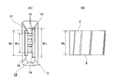
- (A) is the figure which looked at the nozzle for grease application from the downward direction of FIG. 4 (A)
- (B) is the figure which looked at a part of outer peripheral surface of the worm wheel from radial direction.
- the figure for demonstrating the state of the grease apply
- FIG. 3 for demonstrating the problem in the case of not providing a protruding wall part.
- A) And (B) is the same figure as FIG. 5 for demonstrating the problem in the case of not providing a protruding wall part.
- the 2nd example of embodiment of this invention is shown, (A) is a perspective view, (B) is a side view, (C) is the bottom view seen from the downward direction of (B). (A) is the end elevation seen from the left of FIG. 9 (C), (B) is the same figure as FIG. 5 (B).
- the 1st example of another shape of a projection part is shown, (A) is a perspective view and (B) is an end view.
- FIG. 11 shows the 2nd example of another shape of a protrusion part.
- [First example of embodiment] 1 to 6 show a first example of an embodiment of the present invention.
- the feature of the present invention including this example, is that the highly viscous (gel-like) grease 1 is a member to be coated and the recesses (worm wheel teeth 3) of the worm wheel teeth (uneven portions) 3 of the worm wheel 2.
- the structure of the grease application nozzle 5 for reliably feeding the inside of the teeth between the teeth) and preventing the worm wheel 2 and the grease application device 4 from being contaminated by the excess grease 1 It is in.
- the basic structure of the grease application device 4 for applying the grease 1 taken in from the grease pump 6 to the worm wheel teeth 3 of the worm wheel 2 by the grease application gun 7 is the structure of a conventionally known grease application device. It is the same. First, the structure of the grease applying device 4 will be described with reference to FIG.
- the grease application device 4 includes a grease pump 6, a metering valve 8, and a grease application gun 7.
- the grease pump 6 is for feeding (pressure-feeding) the grease 1 stored in the grease container 9 to the metering valve 8 through the hose 10a.
- the metering valve 8 is for adjusting the flow rate and flow velocity of the grease 1 pumped from the grease pump 6 and then feeding the grease 1 to the grease application gun 7 through the hose 10b.
- the grease application gun 7 discharges (extrudes) the grease 1 sent from the metering valve 8 from the grease application nozzle 5 attached to the tip by compressed air sent from the compressed air source 11 through the hose 10c. For application to the worm wheel teeth 3 of the worm wheel 2.
- the grease application nozzle 5 of this example is manufactured by assembling a plurality of parts manufactured by injection molding of synthetic resin, and includes a mounting portion 12 and a body portion 13.
- the mounting portion 12 has a hollow cylindrical shape, and is attached to the distal end portion of the grease application gun 7 by fixing the outer peripheral surface thereof to the distal end portion of the grease application gun 7 or by fixing the inner peripheral surface thereof.
- the body portion 13 is connected to the mounting portion 12 on the downstream side (lower side in FIGS. 2 to 4) of the mounting portion 12 with respect to the flow direction of grease 1 flowing in the grease application nozzle 5 (vertical direction in FIGS. 2 to 4) ⁇ . It is provided in a continuous state.
- a discharge port 14 for discharging the grease 1 is provided on the distal end surface (the lower end surface in FIGS. 2 to 4) of the body portion 13.
- the width of the discharge port 14 (the axial dimension with respect to the direction of the worm wheel 2) W 14, is smaller than the width W 3 of the worm wheel teeth 3 (W 14 ⁇ W 3) .
- the width dimension W 14 of the discharge port 14. Is about 12 mm.
- a plurality of (three in the illustrated example) column parts 15 and 15 are provided between the inner side surfaces of the body part 13 so that the flow of the grease 1 flowing in the body part 13 can be rectified. It is said.
- the column parts 15 and 15 are disposed upstream of the discharge port 14 with respect to the grease flow direction ⁇ .
- the grease discharge speed is not uniform in the width direction of the discharge port 14. Since the grease is supplied from a supply passage provided inside the attachment portion 12, the discharge speed of the region in front of the attachment portion 12 (on the extension line) at the discharge port 14 is high, and both ends of the discharge port 14 are low. By providing the column parts 15 and 15, such non-uniform discharge speed can be suppressed.
- the front end surface of the body portion 13 has one side in a direction ⁇ orthogonal to the width direction of the grease application nozzle 5 and the flow direction ⁇ of the grease 1 flowing in the grease application nozzle 5 (the worm wheel 2 described later).
- the flow flows to a portion of the front end surface of the body portion 13 adjacent to one side of the discharge port 14 with respect to the direction ⁇ (that is, one side portion orthogonal to the width direction of the discharge port 14 with respect to the discharge port 14).
- a projecting portion 16 projecting toward the downstream side in the direction ⁇ is provided.
- the tip end surface of the protruding portion 16 is used as a grease pressing surface portion 17 for feeding the grease 1 discharged from the discharge port 14 into the recesses of the worm wheel teeth 3 while scraping the grease 1 on the worm wheel teeth 3.
- the portion of the front end surface of the body portion 13 adjacent to the other side of the discharge port 14 with respect to the direction ⁇ (the rear side with respect to the rotation direction ⁇ of the worm wheel 2) (that is, the width of the discharge port 14 with respect to the discharge port 14).
- a protruding wall portion 18 that protrudes toward the downstream side in the flow direction ⁇ is provided on the other side portion orthogonal to the direction).
- the discharge port 14 of the grease application nozzle 5 is connected to the worm wheel teeth 3 as shown in FIGS. Close to.
- the distance d 16 between the worm wheel tooth 3 and the protrusion 16 in the flow direction ⁇ is also smaller than the distance d 14 between the discharge port 14 and larger than the distance d 18 between the protrusion wall 18. (D 18 ⁇ d 16 ⁇ d 14 ).
- the distance d16 between the worm wheel teeth 3 and the protrusions 16 is determined according to the amount (application thickness) of the grease 1 applied to the worm wheel teeth 3 and is, for example, about 1.5 mm.
- the distance d 18 between the worm wheel tooth 3 and the protruding wall portion 18 should be as small as possible when the grease 1 is applied as long as interference (contact) between the worm wheel tooth 3 and the protruding wall portion 18 can be prevented.
- the position where the discharge port 14 is approached is biased (offset) to one side in the direction ⁇ from the virtual plane ⁇ passing through the central axis of the worm wheel 2 and parallel to the flow direction ⁇ . ) Position.
- the arrangement direction of the grease application nozzle 5 (the flow direction ⁇ of the grease 1 flowing in the grease application nozzle 5) can be a vertical direction or a horizontal direction.
- the worm wheel 2 is rotated at a constant speed in the counterclockwise direction ⁇ of FIGS. 2 to 3 by a drive source such as an electric motor (not shown).
- a drive source such as an electric motor (not shown).
- the grease 1 stored in the grease container 9 is fed into the grease application gun 7 via the grease pump 6 and the metering valve 8.
- the grease 1 fed into the grease application gun 7 is directed from the discharge port 14 of the grease application nozzle 5 attached to the tip of the grease application gun 7 toward the worm wheel teeth 3 with a constant flow rate. Discharge (flow out).
- the grease 1 discharged from the discharge port 14 and adhering to the worm wheel teeth 3 is crushed by the grease pressing surface portion 17 provided on the front end surface of the protruding portion 16 as the worm wheel 2 rotates.
- the grease 1 is scraped and leveled and fed into the recesses of the worm wheel teeth 3 (filled into the recesses of the worm wheel teeth 3). That is, as shown by a range A in FIG. 6, the width dimension w A of the grease 1 attached to the worm wheel teeth 3 immediately after being discharged from the discharge port 14 is substantially the same as the width dimension W 14 of the discharge port 14. smaller than the width W 3 of the worm wheel teeth 3 (w a ⁇ W 14 ⁇ W 3).
- the thickness of the grease 1 is set so that the width dimension w B of the grease 1 attached to the worm wheel teeth 3 is the same as the width dimension W 3 of the worm wheel teeth 3.
- the worm wheel teeth 3 are scraped and averaged so as to be substantially uniform in the width direction and the circumferential direction, and a part thereof is fed into the recesses of the worm wheel teeth 3. Accordingly, the grease 1 can be reliably fed into the recesses of the worm wheel teeth 3 (spread throughout the recesses).
- a protruding wall portion 18 is provided on the front end surface of the body portion 13, and the grease 1 discharged from the discharge port 14 worms the portion between the front end surface of the body portion 13 and the worm wheel teeth 3.
- the wheel 2 is prevented from moving backward in the rotation direction (in the direction opposite to the arrow ⁇ in FIG. 3). That is, as shown in FIGS. 7 to 8, in the case of the grease application nozzle 5a not provided with the protruding wall portion 18, it is discharged from the discharge port 14a, adheres to the worm wheel teeth 3, and is crushed by the grease pressing surface portion 17a. The excess portion of the grease 1a thus moved moves in the direction of the arrow ⁇ in FIG.
- the excess grease 1a adheres to and accumulates on the side surface of the body portion 13a ⁇ the rear side surface in the rotational direction of the worm wheel 2 (the right side surface in FIG. 7) ⁇ . And if it peels off from the side surface of the body part 13a, the problem that the worm wheel 2 and the grease applying device 4 become dirty may occur.
- the width W 14 of the discharge port 14 is smaller than the width W 3 of the worm wheel teeth 3 (W 14 ⁇ W 3) for, Even if it is crushed by the grease pressing surface portion 17a, the grease 1 attached to the worm wheel teeth 3 is unlikely to become excessive.
- a protruding wall portion 18 is provided on a portion of the front end surface of the body portion 13 adjacent to the rear side of the discharge port 14 with respect to the rotation direction of the worm wheel 2.
- the grease application nozzle 5 of this example it is possible to prevent the excessive amount of the grease 1 from adhering to and accumulating on the side surface of the body portion 13 (the rear side surface in the rotational direction of the worm wheel 2). It is possible to prevent the grease application device 4 from becoming dirty.
- the worm wheel 2 is rotated at a constant angular velocity, and the flow rate of the grease 1 discharged from the grease application nozzle 5 is constant.
- the rotational speed of the worm wheel 2 can be changed in a state where the flow rate of the grease 1 discharged from the grease application nozzle 5 is constant.
- the rotational phase of the worm wheel 2 is detected, and the rotational speed of the worm wheel 2 is controlled to be slowed in a state where the discharge port 14 faces the concave portion of the worm wheel tooth 3.
- the grease 1 can be reliably fed into the recess of the worm wheel tooth 3.
- a protrusion 16a provided on the front end surface of the body portion 13b is composed of a plurality of projections 19 (19 in the example shown).
- Each of the protrusions 19 and 19 has a substantially triangular shape when viewed from the rotational direction of the worm wheel 2 and is provided intermittently in the width direction on the distal end surface of the body portion 13b. That is, in the case of this example, the grease pressing surface portion 17b constituted by the tip surfaces of the protrusions 19 and 19 has a waveform.
- the width dimension of the grease pressing surface portion 17b (the dimension between the tip portions of the projections 19 and 19 positioned at both ends in the width direction among the projections 19 and 19) W 17b is the width dimension W 3 of the worm wheel tooth 3. (W 17b ⁇ W 3 ).
- the amount of crushing of the grease 1 adhered to the worm wheel teeth 3 by the grease pressing surface portion 17b can be adjusted. Accordingly, it is possible to reduce the amount of grease 1 that moves rearward in the rotational direction of the worm wheel 2 along the portion between the front end surface of the body portion 13 b and the worm wheel teeth 3. Further, since the grease pressing surface portion 17b is corrugated, the adhesion of the grease 1 to the worm wheel teeth 3 can be improved. That is, the cutting oil used for forming the worm wheel teeth adheres to the worm wheel teeth in a state where the worm wheel is taken out from the processing apparatus.
- the oil film interposed between the worm wheel teeth 3 and the grease 1 can be broken, and the adhesion of the grease 1 to the worm wheel teeth 3 can be further improved.
- the shape of each of the protrusions 19 and 19 is substantially triangular, a flow directed outward in the width direction is easily induced in the grease 1 at both ends in the width direction of the grease pressing surface portion 17b. Therefore, even when the amount of crushing of the grease 1 is adjusted, the thickness of the grease 1 is substantially uniform over the width direction of the worm wheel teeth 3 (the cross-sectional shape is a waveform along the grease pressing surface portion 17b). Can be leveled.
- the protruding portion is constituted by a plurality of protrusions
- the number and shape of each protrusion can be appropriately changed. That is, for example, the tip portions of the protrusions 19a and 19a are hemispherical like the grease application nozzle 5c shown in FIG. 11, or the number of the protrusions 19b and 19b is set like the grease application nozzle 5d shown in FIG. Can be three.
- the number and shape of such protrusions are determined by design according to the amount and viscosity of the grease applied to the uneven portion of the member to be coated, the depth of the concave portion constituting the uneven portion, and the like.
- the configuration and operation of the other parts are the same as in the first example of the embodiment described above.
- the grease application nozzle according to the present invention is not limited to the worm wheel used in the description of each example of the embodiment, but, for example, when applying grease to various gear members having irregular portions formed on the inner peripheral surface or the outer peripheral surface. Can be used for
Landscapes
- Engineering & Computer Science (AREA)
- General Engineering & Computer Science (AREA)
- Mechanical Engineering (AREA)
- Coating Apparatus (AREA)
- General Details Of Gearings (AREA)
- Application Of Or Painting With Fluid Materials (AREA)
Abstract
ボディ部(13)の先端面は、吐出口よりもウォームホイール(2)の回転方向前側部分に突出部(16)を設け、この突出部(16)の先端面に、グリース(1)を、ウォームホイール歯(3)の幅方向及び円周方向に関してほぼ均一となる様に掻き均しつつ、このウォームホイール歯(3)の凹部内に押し込むグリース押面部(17)を設ける。又、前記ボディ部(13)の先端面は、前記吐出口よりも前記ウォームホイール(2)の回転方向後側部分に、前記グリース(1)が、このウォームホイール(2)の回転方向に関して後方へと移動するのを防止する為の突壁部(18)を設ける。
Description
この発明は、例えば、ウォームホイール等の様に、外周面又は内周面に凹凸部(歯部)が形成された被塗布部材に対してグリースを塗布する為のグリース塗布用ノズルの改良に関する。
自動車や各種産業機械の動力伝達部には、多くの歯車が組み込まれており、この様な歯車同士の噛合部をグリースにより潤滑する事が行われている。特に、各歯車の耐久性を向上させる為に、高粘度の(JISちょう度番号が3以上である)グリースを使用する場合がある。具体的には、例えば、電動式パワーステアリング装置に組み込まれるウォーム式減速機を構成するウォーム軸のウォーム歯とウォームホイールのウォームホイール歯との噛合部の潤滑が、高粘度のグリースにより行われている。
上述の様なウォーム軸とウォームホイールとは、ウォーム歯とウォームホイール歯とのうちの少なくとも一方にグリースを塗布した状態で組み付ける。ウォームホイール等の様に、外周面又は内周面に形成された、円周方向に関する凹凸部(歯部)に対して、高粘度のグリースを塗布する方法としては、例えば、次の様な方法が考えられる。グリースを吐出する(流出する)吐出口を、凹凸部に近接させた状態で円周方向に亙り間欠的に設ける。そして、各吐出口から凹凸部に向けて、グリースを吐出する事により塗布する。但し、この様な方法では、グリースを均一に塗布する事が難く、特に、グリースを、凹凸部の凹部内に押し込めない(凹部内の全体に行き渡らせる事ができない)可能性がある。
特許文献1には、被塗布部材(基材5)の円筒面(の一部)に、所謂平ノズル(ノズル6)を用いてある程度の粘度を有する流体(塗料12)を塗布する技術が記載されている。但し、前記特許文献1に記載されたノズルは、円周方向に関する凹凸部に高粘度のグリースを塗布する事を考慮しておらず、特許文献1に記載されたノズルを用いて凹凸部にグリースを塗布しても、凹凸部の凹部内にグリースを十分に送り込めない可能性がある。
なお、括弧内は、特許文献1に記載の符号を示す。
なお、括弧内は、特許文献1に記載の符号を示す。
本発明は、上述の様な事情に鑑みて、グリースを、被塗布部材の凹凸部の凹部内に確実に押し込む事ができ、しかも、余剰なグリースにより、被塗布部材や塗布装置等が汚れるのを防止する事ができる、グリース塗布用ノズルの構造を実現するものである。
本発明のグリース塗布用ノズルは、ボディ部の先端面に開口する状態で吐出口を設けている。そして、吐出口を、例えば歯車等の被塗布部材の周面(外周面又は内周面)に形成された円周方向に関する凹凸部(歯部)に近接させた状態で、被塗布部材を自身の中心軸を中心として回転させながら、前記吐出口から高粘度のグリースを吐出する事により、前記凹凸部に対して、前記被塗布部材の回転方向に関して前側から後側に連続的に塗布する。
特に本発明のグリース塗布用ノズルに於いては、前記ボディ部の先端面は、前記吐出口よりも前記被塗布部材の回転方向前側部分に、吐出口から吐出されて前記凹凸部に付着した前記グリースを、前記凹凸部の幅方向及び円周方向に関してほぼ均一となる様に掻き均しつつ、凹凸部の凹部内に前記グリースを押し込む(充填する)グリース押面部を設けている。
又、前記ボディ部の先端面は、前記吐出口よりも前記被塗布部材の回転方向後側部分に、ボディ部の先端面から突出する状態で、前記グリース押面部により掻き均された前記グリースの余剰分が、前記被塗布部材の回転方向に関して後方へと移動するのを防止する為の突壁部を設けている。
又、前記ボディ部の先端面は、前記吐出口よりも前記被塗布部材の回転方向後側部分に、ボディ部の先端面から突出する状態で、前記グリース押面部により掻き均された前記グリースの余剰分が、前記被塗布部材の回転方向に関して後方へと移動するのを防止する為の突壁部を設けている。
上述の様な本発明のグリース塗布用ノズルを実施する場合に好ましくは、前記グリース押面部を、前記ボディ部の先端面の、前記吐出口よりも前記被塗布部材の回転方向前側部分に、ボディ部の先端面から突出する状態で設けられた突出部の先端面に設ける。
この様な発明を実施する場合に好ましくは、前記突出部を、前記ボディ部の幅方向に関して間欠的に設けられた複数の突起から構成する。
この様な発明を実施する場合に好ましくは、前記突出部を、前記ボディ部の幅方向に関して間欠的に設けられた複数の突起から構成する。
上述の様な本発明のグリース塗布用ノズルを実施する場合に好ましくは、前記吐出口の幅寸法を前記凹凸部の幅寸法よりも小さく、前記突壁部の幅寸法及び前記グリース押面部の幅寸法を何れも、凹凸部の幅寸法以上とする。
上述の様に構成する本発明のグリース塗布用ノズルによれば、グリースを、被塗布部材の凹凸部の凹部内に確実に押し込む(凹部内に確実に充填する)事ができ、しかも、余剰なグリースにより、被塗布部材や塗布装置等が汚れるのを防止できる。
即ち、ボディ部の先端面は、吐出口よりも被塗布部材の回転方向前側部分にグリース押面部を設け、グリース押面部により、吐出口から吐出されて凹凸部に付着したグリースを掻き均しつつ、凹凸部の凹部に押し込める様にしている。従って、グリースを、凹凸部の凹部内に確実に送り込む(凹部内の全体に行き渡らせる)事ができる。
又、ボディ部の先端面は、吐出口よりも被塗布部材の回転方向後側部分に突壁部を設けている。これにより、グリースが、ボディ部の先端面と凹凸部との間部分を、被塗布部材の回転方向後方へと移動するのを防止できる。この結果、グリースが、ボディ部の、被塗布部材の回転方向に関する後側面に付着・堆積し、この後側面から剥れ落ちて、被塗布部材やグリース塗布用ノズルを組み込んだ塗布装置等が汚れるのを防止する事ができる。
即ち、ボディ部の先端面は、吐出口よりも被塗布部材の回転方向前側部分にグリース押面部を設け、グリース押面部により、吐出口から吐出されて凹凸部に付着したグリースを掻き均しつつ、凹凸部の凹部に押し込める様にしている。従って、グリースを、凹凸部の凹部内に確実に送り込む(凹部内の全体に行き渡らせる)事ができる。
又、ボディ部の先端面は、吐出口よりも被塗布部材の回転方向後側部分に突壁部を設けている。これにより、グリースが、ボディ部の先端面と凹凸部との間部分を、被塗布部材の回転方向後方へと移動するのを防止できる。この結果、グリースが、ボディ部の、被塗布部材の回転方向に関する後側面に付着・堆積し、この後側面から剥れ落ちて、被塗布部材やグリース塗布用ノズルを組み込んだ塗布装置等が汚れるのを防止する事ができる。
[実施の形態の第1例]
図1~6は、本発明の実施の形態の第1例を示している。尚、本例を含めて、本発明の特徴は、高粘度の(ゲル状の)グリース1を、被塗布部材でありウォームホイール2のウォームホイール歯(凹凸部)3の凹部(ウォームホイール歯3を構成する各歯同士の間部分)の内側に確実に送り込んで、しかも、余剰なグリース1により、ウォームホイール2やグリース塗布装置4等が汚れるのを防止する為のグリース塗布用ノズル5の構造にある。グリースポンプ6から取り込んだグリース1を、グリース塗布ガン7により、ウォームホイール2のウォームホイール歯3に塗布する為のグリース塗布装置4の基本的構造は、従来から知られているグリース塗布装置の構造と同様である。先ず、グリース塗布装置4の構造に就いて、図1により説明する。
図1~6は、本発明の実施の形態の第1例を示している。尚、本例を含めて、本発明の特徴は、高粘度の(ゲル状の)グリース1を、被塗布部材でありウォームホイール2のウォームホイール歯(凹凸部)3の凹部(ウォームホイール歯3を構成する各歯同士の間部分)の内側に確実に送り込んで、しかも、余剰なグリース1により、ウォームホイール2やグリース塗布装置4等が汚れるのを防止する為のグリース塗布用ノズル5の構造にある。グリースポンプ6から取り込んだグリース1を、グリース塗布ガン7により、ウォームホイール2のウォームホイール歯3に塗布する為のグリース塗布装置4の基本的構造は、従来から知られているグリース塗布装置の構造と同様である。先ず、グリース塗布装置4の構造に就いて、図1により説明する。
グリース塗布装置4は、グリースポンプ6と、定量弁8と、グリース塗布ガン7とを備えている。グリースポンプ6は、グリース容器9に貯留されたグリース1を、ホース10aを通して定量弁8に送り込む(圧送する)為のものである。定量弁8は、グリースポンプ6から圧送されたグリース1の流量及び流速を調整した後、グリース1を、ホース10bを通してグリース塗布ガン7に送り込む為のものである。グリース塗布ガン7は、定量弁8から送り込まれたグリース1を、圧縮空気源11からホース10cを通して送り込まれる圧縮空気により、先端部に取り付けたグリース塗布用ノズル5から吐出して(押し出して)、ウォームホイール2のウォームホイール歯3に塗布する為のものである。
本例のグリース塗布用ノズル5は、合成樹脂の射出成形により造られた複数の部品を組み立てる等して造られたもので、取付部12と、ボディ部13とを備えている。取付部12は、中空円筒状であり、グリース塗布ガン7の先端部に外周面を内嵌固定する、或いは、内周面を外嵌固定する事により、グリース塗布ガン7の先端部に取り付けられる。ボディ部13は、グリース塗布用ノズル5内を流れるグリース1の流れ方向(図2~4の上下方向)αに関して取付部12の下流側(図2~4の下側)に、取付部12と連続した状態で設けられている。ボディ部13の先端面(図2~4の下端面)には、グリース1を吐出する為の吐出口14が設けられている。本例の場合、吐出口14の幅寸法(ウォームホイール2の軸方向に関する寸法)W14を、ウォームホイール歯3の幅寸法W3よりも小さくしている(W14<W3)。具体的には、例えば、自動車用の電動式パワーステアリング装置に組み込まれる、16mm程度の幅寸法W3を有するウォームホイール歯3にグリース1を塗布する場合には、吐出口14の幅寸法W14を12mm程度とする。但し、吐出口14の幅寸法W14をウォームホイール歯3の幅寸法W13よりも小さくする程度は、塗布するグリース1の量(塗布厚さ)や粘度、ウォームホイール歯3の歯丈(凹部の深さ)等に応じて設計的に定める。又、ボディ部13の内側面同士の間には、複数本(図示の例では3本)の柱部15、15を掛け渡す状態で設け、ボディ部13内を流れるグリース1の流れを整流可能としている。
柱部15、15は、吐出口14よりもグリースの流れ方向αに関して上流側に配置されている。柱部15、15が存在しない場合、グリースの吐出速度は吐出口14の幅方向に関して不均一となる。グリースは取付部12の内部に設けられた供給通路から供給されるため、吐出口14において取付部12の正面(延長線上)にある領域の吐出速度が高く、吐出口14の両端が低くなる。柱部15、15を設けることで、このような吐出速度の不均一を抑制することができる。
ボディ部13の先端面は、グリース塗布用ノズル5の幅方向と、グリース塗布用ノズル5内を流れるグリース1の流れ方向αとの、それぞれに直交する方向βの片側(後述するウォームホイール2の回転方向γに関して前側、図2~3の左側)に向かう程、この流れ方向αの下流側(図2~3の下側)に向かう方向に傾斜している。又、ボディ部13の先端面の、前記方向βに関して吐出口14の片側に隣接する部分(即ち、吐出口14に対して吐出口14の幅方向に対して直交する一方側部分)に、流れ方向αの下流側に向けて突出する突出部16を設けている。そして、突出部16の先端面を、吐出口14から吐出されたグリース1をウォームホイール歯3上で掻き均しつつ、ウォームホイール歯3の凹部内に送り込む為のグリース押面部17としている。一方、ボディ部13の先端面の、前記方向βに関して吐出口14の他側(ウォームホイール2の回転方向γに関して後側)に隣接する部分(即ち、吐出口14に対して吐出口14の幅方向に対して直交する他方側部分)に、流れ方向αの下流側に向けて突出する突壁部18を設けている。本例の場合、グリース押面部17の幅寸法W17、及び、突壁部18の幅寸法W18を何れも、ウォームホイール歯3の幅寸法W3以上としている(W17≧W3、W18≧W3)。
グリース塗布装置4によりウォームホイール2のウォームホイール歯3に、高粘度のグリース1を塗布する際には、図2~3に示す様に、グリース塗布用ノズル5の吐出口14をウォームホイール歯3に近接させる。この状態で、流れ方向αに関する、ウォームホイール歯3と突出部16との間隔d16を、同じく吐出口14との間隔d14よりも小さく、同じく突壁部18との間隔d18より大きくしている(d18<d16<d14)。ウォームホイール歯3と突出部16との間隔d16は、ウォームホイール歯3に塗布するグリース1の量(塗布厚さ)に応じて定められ、例えば1.5mm程度である。一方、ウォームホイール歯3と突壁部18との間隔d18は、グリース1を塗布する際に、ウォームホイール歯3と突壁部18との干渉(接触)を防止できる限り、できるだけ小さくする事が望ましく、例えば0.5mm程度とする事ができる。又、本例の場合、吐出口14を近接させる位置を、ウォームホイール2の中心軸を通り、流れ方向αに平行な仮想平面δよりも、前記方向βの片側に偏らせた(オフセットさせた)位置としている。尚、グリース塗布用ノズル5の配設方向(グリース塗布用ノズル5内を流れるグリース1の流れ方向α)は、鉛直方向とする事もできるし、水平方向とする事もできる。
何れにしても、この状態で、ウォームホイール2を図示しない電動モータ等の駆動源により、図2~3の反時計方向γに、一定速度で回転させる。同時に、グリース容器9に貯留されたグリース1を、グリースポンプ6と定量弁8とを介してグリース塗布ガン7内に送り込む。そして、グリース塗布ガン7内に送り込まれたグリース1を、流量を一定とした状態で、グリース塗布ガン7の先端部に取り付けたグリース塗布用ノズル5の吐出口14からウォームホイール歯3に向けて吐出する(流出させる)。
吐出口14から吐出され、ウォームホイール歯3に付着したグリース1を、ウォームホイール2の回転に伴い、突出部16の先端面に設けたグリース押面部17により押し潰す。これにより、グリース1を掻き均しつつ、ウォームホイール歯3の凹部内に送り込む(ウォームホイール歯3の凹部内に充填する)。即ち、図6に範囲Aで示す様に、吐出口14から吐出された直後のウォームホイール歯3に付着したグリース1の幅寸法wAは、吐出口14の幅寸法W14とほぼ同じで、ウォームホイール歯3の幅寸法W3よりも小さい(wA≒W14<W3)。この状態から、ウォームホイール2の回転に伴い、ウォームホイール歯3に付着したグリース1をグリース押面部17により押し潰す。この結果、図6に範囲Bで示す様に、ウォームホイール歯3に付着したグリース1の幅寸法wBが、ウォームホイール歯3の幅寸法W3と同じになる様に、グリース1の厚さが、ウォームホイール歯3の幅方向及び円周方向に関してほぼ均一となる様に掻き均されると共に、一部がウォームホイール歯3の凹部内に送り込まれる。従って、グリース1を、ウォームホイール歯3の凹部内に確実に送り込む(凹部内の全体に行き渡らせる)事ができる。
又、本例の場合、ボディ部13の先端面に突壁部18を設け、吐出口14から吐出されたグリース1が、ボディ部13の先端面とウォームホイール歯3との間部分を、ウォームホイール2の回転方向後方(図3の矢印γと逆方向)に移動するのを防止している。即ち、図7~8に示す様に、突壁部18を設けていないグリース塗布用ノズル5aの場合、吐出口14aから吐出されて、ウォームホイール歯3に付着し、グリース押面部17aにより押し潰されたグリース1aの余剰分が、ボディ部13aの先端面とウォームホイール歯3との間部分に沿って、図7の矢印ε方向(ウォームホイール2の回転方向後方)に移動する。特に、図7~8に示した例の場合には、吐出口14aの幅寸法W14aと、ウォームホイール歯3の幅寸法W3とを互いに同じとしている(W14a=W3)としている為、グリース1aが余剰となり易い。グリース1aの余剰分は、ボディ部13aの側面{ウォームホイール2の回転方向に関する後側面(図7の右側面)}に付着・堆積する。そして、ボディ部13aの側面から剥れ落ちると、ウォームホイール2やグリース塗布装置4が汚れると言った問題を生じる可能性がある。
これに対し、本例のグリース塗布用ノズル5の場合には、吐出口14の幅寸法W14をウォームホイール歯3の幅寸法W3よりも小さくしている(W14<W3)為、グリース押面部17aにより押し潰されても、ウォームホイール歯3に付着したグリース1が余剰となり難い。更に、本例の場合には、ボディ部13の先端面の、ウォームホイール2の回転方向に関して吐出口14の後側に隣接する部分に、突壁部18を設けている。この為、グリース1の余剰分が、ボディ部13の先端面とウォームホイール歯3との間部分に沿って、ウォームホイール2の回転方向後方に移動しようとすると、突壁部18により堰き止められる。尚、本例の場合、ウォームホイール歯3と突壁部18との干渉を防止する為、ウォームホイール歯3と突壁部18との間に微小隙間(0.5mm程度の隙間)を設けている。但し、グリース1として粘度の高いものを使用している為、グリース1が微小隙間を通じてウォームホイール2の回転方向後方へと移動する事を防止できる。従って、本例のグリース塗布用ノズル5によれば、グリース1の余剰分が、ボディ部13の側面(ウォームホイール2の回転方向に関する後側面)に付着・堆積するのを防止でき、ウォームホイール2やグリース塗布装置4が汚れる事を防止する事ができる。
尚、本例の場合、ウォームホイール2を一定の角速度で回転させると共に、グリース塗布用ノズル5から吐出するグリース1の流量を一定としている。但し、グリース塗布用ノズル5から吐出するグリース1の流量を一定とした状態で、ウォームホイール2の回転速度を変化させる事もできる。具体的には、ウォームホイール2の回転位相を検出し、吐出口14がウォームホイール歯3の凹部に対向した状態で、ウォームホイール2の回転速度を遅くする様に規制する。これにより、ウォームホイール歯3の凹部内により確実にグリース1を送り込む事ができる。
[実施の形態の第2例]
図9~10は、本発明の実施の形態の第2例を示している。本例のグリース塗布用ノズル5bは、ボディ部13bの先端面に設けた突出部16aを、複数個(図示の例の場合には5個)の突起19、19から構成している。各突起19、19は、ウォームホイール2の回転方向から見た形状を、略三角形状とし、ボディ部13bの先端面に、幅方向に間欠的に設けられている。即ち、本例の場合、各突起19、19の先端面により構成されるグリース押面部17bを波形としている。又、グリース押面部17bの幅寸法(各突起19、19のうち、幅方向両端に位置する突起19、19の先端部同士の間の寸法)W17bを、ウォームホイール歯3の幅寸法W3よりも小さくしている(W17b<W3)。
図9~10は、本発明の実施の形態の第2例を示している。本例のグリース塗布用ノズル5bは、ボディ部13bの先端面に設けた突出部16aを、複数個(図示の例の場合には5個)の突起19、19から構成している。各突起19、19は、ウォームホイール2の回転方向から見た形状を、略三角形状とし、ボディ部13bの先端面に、幅方向に間欠的に設けられている。即ち、本例の場合、各突起19、19の先端面により構成されるグリース押面部17bを波形としている。又、グリース押面部17bの幅寸法(各突起19、19のうち、幅方向両端に位置する突起19、19の先端部同士の間の寸法)W17bを、ウォームホイール歯3の幅寸法W3よりも小さくしている(W17b<W3)。
上述の様な本例のグリース塗布用ノズル5bによれば、グリース押面部17bによる、ウォームホイール歯3に付着したグリース1の押し潰し量を調整する事ができる。従って、ボディ部13bの先端面とウォームホイール歯3との間部分に沿って、ウォームホイール2の回転方向後方に移動するグリース1の量を減少させる事ができる。又、グリース押面部17bを波形としている為、グリース1のウォームホイール歯3に対する密着性をより良好にする事ができる。即ち、ウォームホイールを加工装置から取り出した状態で、ウォームホイール歯には、ウォームホイール歯を形成する為に使用した切削油が付着している。この状態で、ウォームホイール歯に向けてグリースを吐出しても、グリースとウォームホイール歯との間に切削油の油膜が介在した状態となり、十分な密着性を得られず、ウォームホイールの使用時に、ウォームホイールの回転に伴う遠心力によって、グリースが剥れ落ちる可能性がある。これに対し、本例の場合には、グリース押面部17bを波形とする事により、ウォームホイール2の回転に伴って、ウォームホイール歯3に付着したグリース1を、グリース押面部17bにより攪拌しつつ(各突起19、19によりグリース1を幅方向に掻き分けつつ)、押し潰す(ウォームホイール歯3に向けて押し付ける)。この結果、ウォームホイール歯3とグリース1との間に介在する油膜を破壊して、グリース1のウォームホイール歯3に対する密着性をより向上させる事ができる。尚、本例の場合、各突起19、19の形状を略三角形状としている為、グリース押面部17bの幅方向両端部で、グリース1に幅方向外方に向いた流れが惹起され易い。従って、グリース1の押し潰し量を調整した場合でも、グリース1の厚さが、ウォームホイール歯3の幅方向に亙ってほぼ均一となる(断面形状が、グリース押面部17bに沿った波形となる)様に掻き均す事ができる。
本例の様に、突出部を複数の突起により構成する場合、各突起の数や形状は適宜変更する事ができる。即ち、例えば、図11に示すグリース塗布用ノズル5cの様に、突起19a、19aの先端部を半球状としたり、図12に示すグリース塗布用ノズル5dの様に、突起19b、19bの数を3個とする事ができる。この様な突起の数や形状は、被塗布部材の凹凸部に塗布するグリースの量や粘度、凹凸部を構成する凹部の深さ等に応じて設計的に定める。
その他の部分の構成及び作用は、上述した実施の形態の第1例と同様である。
その他の部分の構成及び作用は、上述した実施の形態の第1例と同様である。
本発明のグリース塗布用ノズルは、実施の形態の各例の説明で使用したウォームホイールだけでなく、例えば内周面又は外周面に凹凸部が形成された各種歯車部材に、グリースを塗布する際に用いる事ができる。
本出願は、2015年2月16日出願の日本特許出願2015―027199に基づくものであり、その内容はここに参照として取り込まれる。
1、1a グリース
2 ウォームホイール
3 ウォームホイール歯
4 グリース塗布装置
5、5a~5d グリース塗布用ノズル
6 グリースポンプ
7 グリース塗布ガン
8 定量弁
9 グリース容器
10a~10c ホース
11 圧縮空気源
12 取付部
13、13a ボディ部
14、14a 吐出口
15 柱部
16、16a 突出部
17、17a、17b グリース押面部
18 突壁部
19、19a、19b 突起
2 ウォームホイール
3 ウォームホイール歯
4 グリース塗布装置
5、5a~5d グリース塗布用ノズル
6 グリースポンプ
7 グリース塗布ガン
8 定量弁
9 グリース容器
10a~10c ホース
11 圧縮空気源
12 取付部
13、13a ボディ部
14、14a 吐出口
15 柱部
16、16a 突出部
17、17a、17b グリース押面部
18 突壁部
19、19a、19b 突起
Claims (4)
- ボディ部の先端面に開口する状態で設けられた吐出口を、被塗布部材の周面に形成された円周方向に関する凹凸部に近接させた状態で、前記被塗布部材を自身の中心軸を中心として回転させながら、前記吐出口からグリースを吐出する事により、前記吐出したグリースを前記凹凸部に塗布する
グリース塗布用ノズルであって、
前記ボディ部の先端面には、前記吐出口よりも前記被塗布部材の回転方向前側部分に、前記吐出口から吐出されて前記凹凸部に付着した前記グリースを掻き均しつつ、前記凹凸部の凹部内に前記グリースを押し込むグリース押面部が設けられており、
前記ボディ部の先端面には、前記吐出口よりも前記被塗布部材の回転方向後側部分に、前記ボディ部の先端面から突出する状態で、前記グリース押面部により掻き均された前記グリースの余剰分が、前記被塗布部材の回転方向に関して後方へと移動するのを防止する為の突壁部が設けられている
事を特徴とするグリース塗布用ノズル。 - 前記グリース押面部が、前記ボディ部の先端面の、前記吐出口よりも前記被塗布部材の回転方向前側部分に、前記ボディ部の先端面から突出する状態で設けられた突出部の先端面に設けられている、
請求項1に記載したグリース塗布用ノズル。 - 前記突出部が、前記ボディ部の幅方向に関して間欠的に設けられた複数の突起から構成されている、
請求項2に記載したグリース塗布用ノズル。 - 前記吐出口の幅寸法が前記凹凸部の幅寸法よりも小さく、前記突壁部の幅寸法及び前記グリース押面部の幅寸法が何れも、前記凹凸部の幅寸法以上である
請求項1または2に記載したグリース塗布用ノズル。
Priority Applications (3)
| Application Number | Priority Date | Filing Date | Title |
|---|---|---|---|
| CN201680010020.4A CN107250655B (zh) | 2015-02-16 | 2016-01-29 | 润滑脂涂布用喷嘴 |
| US15/548,139 US10543505B2 (en) | 2015-02-16 | 2016-01-29 | Nozzle for grease application and methods for using |
| EP16752258.0A EP3260753B1 (en) | 2015-02-16 | 2016-01-29 | Nozzle for grease application |
Applications Claiming Priority (2)
| Application Number | Priority Date | Filing Date | Title |
|---|---|---|---|
| JP2015027199A JP6187496B2 (ja) | 2015-02-16 | 2015-02-16 | グリース塗布用ノズル |
| JP2015-027199 | 2015-02-16 |
Publications (1)
| Publication Number | Publication Date |
|---|---|
| WO2016132869A1 true WO2016132869A1 (ja) | 2016-08-25 |
Family
ID=56688837
Family Applications (1)
| Application Number | Title | Priority Date | Filing Date |
|---|---|---|---|
| PCT/JP2016/052790 Ceased WO2016132869A1 (ja) | 2015-02-16 | 2016-01-29 | グリース塗布用ノズル |
Country Status (5)
| Country | Link |
|---|---|
| US (1) | US10543505B2 (ja) |
| EP (1) | EP3260753B1 (ja) |
| JP (1) | JP6187496B2 (ja) |
| CN (1) | CN107250655B (ja) |
| WO (1) | WO2016132869A1 (ja) |
Families Citing this family (7)
| Publication number | Priority date | Publication date | Assignee | Title |
|---|---|---|---|---|
| JP6634984B2 (ja) * | 2016-09-02 | 2020-01-22 | 京セラドキュメントソリューションズ株式会社 | 液体塗布装置 |
| CN106334661B (zh) * | 2016-11-30 | 2019-07-02 | 芜湖全程智能科技有限公司 | 一种丝杆组件涂抹润滑油脂的方法 |
| JP6848758B2 (ja) * | 2017-08-02 | 2021-03-24 | トヨタ自動車株式会社 | 成膜装置 |
| CN107457151A (zh) * | 2017-09-09 | 2017-12-12 | 芜湖润林包装材料有限公司 | 纸护角胶水喷涂机 |
| CN111577875B (zh) * | 2020-04-02 | 2021-10-19 | 武汉船用机械有限责任公司 | 润滑脂喷射装置 |
| US12246522B2 (en) * | 2021-10-05 | 2025-03-11 | The Boeing Company | Nozzles and systems for adhesively attaching a first part to a second part |
| CN116753446A (zh) * | 2023-06-06 | 2023-09-15 | 山东飞越电子科技有限公司 | 一种云台蜗轮蜗杆润滑脂添加装置 |
Citations (3)
| Publication number | Priority date | Publication date | Assignee | Title |
|---|---|---|---|---|
| JPH08233197A (ja) * | 1995-03-01 | 1996-09-10 | Hitachi Constr Mach Co Ltd | ギヤのグリース給脂装置 |
| JPH10156254A (ja) * | 1996-10-02 | 1998-06-16 | Matsushita Electric Ind Co Ltd | 塗布方法及び装置 |
| JP2015013272A (ja) * | 2013-07-08 | 2015-01-22 | トヨタ自動車株式会社 | 塗布装置及び塗布方法 |
Family Cites Families (15)
| Publication number | Priority date | Publication date | Assignee | Title |
|---|---|---|---|---|
| US3854553A (en) * | 1973-11-01 | 1974-12-17 | Caterpillar Tractor Co | Lubrication system for swing gear drive |
| CA1138784A (en) * | 1979-01-03 | 1983-01-04 | Northwest Engineering Company | Mobile power crane-excavator with open gear greasing |
| US4244447A (en) * | 1979-01-08 | 1981-01-13 | Northwest Engineering Company | Mobile power crane-excavator with open gear greasing |
| US6117490A (en) | 1996-10-02 | 2000-09-12 | Matsushita Electric Industrial Co, Ltd. | Coating material application method and an apparatus for use in such a method |
| US5925414A (en) | 1996-11-20 | 1999-07-20 | International Business Corpration | Nozzle and method for extruding conductive paste into high aspect ratio openings |
| EP0919288A3 (en) | 1997-11-25 | 2003-10-08 | Nordson Corporation | Electrostatic dispensing apparatus and method |
| US6902209B2 (en) * | 2002-08-15 | 2005-06-07 | Mcinerney Edward A. | Grease gun adaptor device |
| US7967768B2 (en) | 2003-04-14 | 2011-06-28 | Watts Robert J | Ankle-foot orthosis |
| US20070107773A1 (en) * | 2005-11-17 | 2007-05-17 | Palo Alto Research Center Incorporated | Bifacial cell with extruded gridline metallization |
| JP5276420B2 (ja) * | 2008-01-31 | 2013-08-28 | 大日本スクリーン製造株式会社 | 基板処理装置および基板処理方法 |
| JP5290852B2 (ja) | 2009-04-23 | 2013-09-18 | 日置電機株式会社 | フラックス塗布装置およびフラックス塗布方法 |
| US9033109B2 (en) * | 2012-01-31 | 2015-05-19 | General Electric Company | System and method for lubricating gears in a wind turbine |
| JP6142268B2 (ja) | 2013-05-28 | 2017-06-07 | 兵神装備株式会社 | 吐出幅可変装置、及び吐出装置 |
| DE102014209101A1 (de) * | 2014-05-14 | 2015-11-19 | Skf Lubrication Systems Germany Gmbh | Dosiereinrichtung zum dosierten Ausbringen eines Schmierfetts auf eine Fläche, Verfahren zum dosierten Ausbringen eines Schmierfetts auf eine Fläche |
| JP6265152B2 (ja) * | 2015-03-02 | 2018-01-24 | 日本精工株式会社 | グリース塗布方法及び塗布装置、並びに、ウォーム減速機の製造方法、電動式パワーステアリング装置の製造方法、自動車の製造方法及び産業機械の製造方法 |
-
2015
- 2015-02-16 JP JP2015027199A patent/JP6187496B2/ja not_active Expired - Fee Related
-
2016
- 2016-01-29 US US15/548,139 patent/US10543505B2/en active Active
- 2016-01-29 WO PCT/JP2016/052790 patent/WO2016132869A1/ja not_active Ceased
- 2016-01-29 CN CN201680010020.4A patent/CN107250655B/zh active Active
- 2016-01-29 EP EP16752258.0A patent/EP3260753B1/en active Active
Patent Citations (3)
| Publication number | Priority date | Publication date | Assignee | Title |
|---|---|---|---|---|
| JPH08233197A (ja) * | 1995-03-01 | 1996-09-10 | Hitachi Constr Mach Co Ltd | ギヤのグリース給脂装置 |
| JPH10156254A (ja) * | 1996-10-02 | 1998-06-16 | Matsushita Electric Ind Co Ltd | 塗布方法及び装置 |
| JP2015013272A (ja) * | 2013-07-08 | 2015-01-22 | トヨタ自動車株式会社 | 塗布装置及び塗布方法 |
Also Published As
| Publication number | Publication date |
|---|---|
| US10543505B2 (en) | 2020-01-28 |
| CN107250655B (zh) | 2019-09-27 |
| EP3260753A4 (en) | 2018-07-04 |
| CN107250655A (zh) | 2017-10-13 |
| EP3260753A1 (en) | 2017-12-27 |
| EP3260753B1 (en) | 2020-03-04 |
| JP2016151280A (ja) | 2016-08-22 |
| JP6187496B2 (ja) | 2017-08-30 |
| US20180036759A1 (en) | 2018-02-08 |
Similar Documents
| Publication | Publication Date | Title |
|---|---|---|
| JP6187496B2 (ja) | グリース塗布用ノズル | |
| EP0870546B1 (en) | Powder spray gun with rotary distributor | |
| JP3631084B2 (ja) | 塗装品およびその製造方法および塗装装置 | |
| EP2429716B1 (fr) | Projecteur et organe de pulverisation de produit de revetement et procede de projection mettant en oeuvre un tel projecteur | |
| US5816508A (en) | Powder spray gun with rotary distributor | |
| JP2016161033A5 (ja) | ||
| CN101440853B (zh) | 带有润滑剂的橡胶衬套及其制造方法 | |
| US12285936B2 (en) | Device, method, and assembly for loading nozzles with fluid | |
| CA3093536C (en) | Mixing device comprising a seal | |
| WO2012150471A1 (en) | Bead forming tip for caulking guns | |
| JP2012519069A (ja) | 修理ノズル | |
| CN112771293A (zh) | 密封装置和润滑脂附着方法 | |
| JP2012071110A5 (ja) | ||
| CN107405643A (zh) | 润滑脂涂布装置及润滑脂涂布方法 | |
| EP3833487B1 (en) | Fluid tip for spray applicator | |
| JP3974909B2 (ja) | 塗装品の製造方法および塗装品 | |
| CN211105656U (zh) | 一种应用于sla型3d打印机的带辊刮刀装置 | |
| FR2915114A1 (fr) | Organe de pulverisation,dispositif de projection comportant un tel organe et installation de projection comprenant un tel dispositif | |
| JPS6324195B2 (ja) | ||
| US11612908B2 (en) | Nozzle having quadrilateral outlet for viscous material distribution | |
| JP5983050B2 (ja) | ボールねじ装置 | |
| EP2777825B1 (en) | Coating application | |
| JP6235963B2 (ja) | 回転霧化式静電塗装機 | |
| KR20120031114A (ko) | 접착제의 도포 장치 | |
| JP7369483B1 (ja) | 流体供給装置並びに流体塗布装置及び流体充填装置 |
Legal Events
| Date | Code | Title | Description |
|---|---|---|---|
| 121 | Ep: the epo has been informed by wipo that ep was designated in this application |
Ref document number: 16752258 Country of ref document: EP Kind code of ref document: A1 |
|
| WWE | Wipo information: entry into national phase |
Ref document number: 15548139 Country of ref document: US |
|
| REEP | Request for entry into the european phase |
Ref document number: 2016752258 Country of ref document: EP |
|
| NENP | Non-entry into the national phase |
Ref country code: DE |