WO2016132912A1 - ハニカム構造体の製造方法 - Google Patents
ハニカム構造体の製造方法 Download PDFInfo
- Publication number
- WO2016132912A1 WO2016132912A1 PCT/JP2016/053304 JP2016053304W WO2016132912A1 WO 2016132912 A1 WO2016132912 A1 WO 2016132912A1 JP 2016053304 W JP2016053304 W JP 2016053304W WO 2016132912 A1 WO2016132912 A1 WO 2016132912A1
- Authority
- WO
- WIPO (PCT)
- Prior art keywords
- exhaust gas
- honeycomb structure
- honeycomb
- manufacturing
- particles
- Prior art date
- Legal status (The legal status is an assumption and is not a legal conclusion. Google has not performed a legal analysis and makes no representation as to the accuracy of the status listed.)
- Ceased
Links
Images


Classifications
-
- C—CHEMISTRY; METALLURGY
- C04—CEMENTS; CONCRETE; ARTIFICIAL STONE; CERAMICS; REFRACTORIES
- C04B—LIME, MAGNESIA; SLAG; CEMENTS; COMPOSITIONS THEREOF, e.g. MORTARS, CONCRETE OR LIKE BUILDING MATERIALS; ARTIFICIAL STONE; CERAMICS; REFRACTORIES; TREATMENT OF NATURAL STONE
- C04B38/00—Porous mortars, concrete, artificial stone or ceramic ware; Preparation thereof
- C04B38/06—Porous mortars, concrete, artificial stone or ceramic ware; Preparation thereof by burning-out added substances by burning natural expanding materials or by sublimating or melting out added substances
-
- C—CHEMISTRY; METALLURGY
- C04—CEMENTS; CONCRETE; ARTIFICIAL STONE; CERAMICS; REFRACTORIES
- C04B—LIME, MAGNESIA; SLAG; CEMENTS; COMPOSITIONS THEREOF, e.g. MORTARS, CONCRETE OR LIKE BUILDING MATERIALS; ARTIFICIAL STONE; CERAMICS; REFRACTORIES; TREATMENT OF NATURAL STONE
- C04B35/00—Shaped ceramic products characterised by their composition; Ceramics compositions; Processing powders of inorganic compounds preparatory to the manufacturing of ceramic products
- C04B35/515—Shaped ceramic products characterised by their composition; Ceramics compositions; Processing powders of inorganic compounds preparatory to the manufacturing of ceramic products based on non-oxide ceramics
- C04B35/56—Shaped ceramic products characterised by their composition; Ceramics compositions; Processing powders of inorganic compounds preparatory to the manufacturing of ceramic products based on non-oxide ceramics based on carbides or oxycarbides
- C04B35/5607—Shaped ceramic products characterised by their composition; Ceramics compositions; Processing powders of inorganic compounds preparatory to the manufacturing of ceramic products based on non-oxide ceramics based on carbides or oxycarbides based on refractory metal carbides
- C04B35/5611—Shaped ceramic products characterised by their composition; Ceramics compositions; Processing powders of inorganic compounds preparatory to the manufacturing of ceramic products based on non-oxide ceramics based on carbides or oxycarbides based on refractory metal carbides based on titanium carbides
-
- C—CHEMISTRY; METALLURGY
- C04—CEMENTS; CONCRETE; ARTIFICIAL STONE; CERAMICS; REFRACTORIES
- C04B—LIME, MAGNESIA; SLAG; CEMENTS; COMPOSITIONS THEREOF, e.g. MORTARS, CONCRETE OR LIKE BUILDING MATERIALS; ARTIFICIAL STONE; CERAMICS; REFRACTORIES; TREATMENT OF NATURAL STONE
- C04B35/00—Shaped ceramic products characterised by their composition; Ceramics compositions; Processing powders of inorganic compounds preparatory to the manufacturing of ceramic products
- C04B35/515—Shaped ceramic products characterised by their composition; Ceramics compositions; Processing powders of inorganic compounds preparatory to the manufacturing of ceramic products based on non-oxide ceramics
- C04B35/56—Shaped ceramic products characterised by their composition; Ceramics compositions; Processing powders of inorganic compounds preparatory to the manufacturing of ceramic products based on non-oxide ceramics based on carbides or oxycarbides
- C04B35/5607—Shaped ceramic products characterised by their composition; Ceramics compositions; Processing powders of inorganic compounds preparatory to the manufacturing of ceramic products based on non-oxide ceramics based on carbides or oxycarbides based on refractory metal carbides
- C04B35/5622—Shaped ceramic products characterised by their composition; Ceramics compositions; Processing powders of inorganic compounds preparatory to the manufacturing of ceramic products based on non-oxide ceramics based on carbides or oxycarbides based on refractory metal carbides based on zirconium or hafnium carbides
-
- C—CHEMISTRY; METALLURGY
- C04—CEMENTS; CONCRETE; ARTIFICIAL STONE; CERAMICS; REFRACTORIES
- C04B—LIME, MAGNESIA; SLAG; CEMENTS; COMPOSITIONS THEREOF, e.g. MORTARS, CONCRETE OR LIKE BUILDING MATERIALS; ARTIFICIAL STONE; CERAMICS; REFRACTORIES; TREATMENT OF NATURAL STONE
- C04B35/00—Shaped ceramic products characterised by their composition; Ceramics compositions; Processing powders of inorganic compounds preparatory to the manufacturing of ceramic products
- C04B35/515—Shaped ceramic products characterised by their composition; Ceramics compositions; Processing powders of inorganic compounds preparatory to the manufacturing of ceramic products based on non-oxide ceramics
- C04B35/56—Shaped ceramic products characterised by their composition; Ceramics compositions; Processing powders of inorganic compounds preparatory to the manufacturing of ceramic products based on non-oxide ceramics based on carbides or oxycarbides
- C04B35/5607—Shaped ceramic products characterised by their composition; Ceramics compositions; Processing powders of inorganic compounds preparatory to the manufacturing of ceramic products based on non-oxide ceramics based on carbides or oxycarbides based on refractory metal carbides
- C04B35/5626—Shaped ceramic products characterised by their composition; Ceramics compositions; Processing powders of inorganic compounds preparatory to the manufacturing of ceramic products based on non-oxide ceramics based on carbides or oxycarbides based on refractory metal carbides based on tungsten carbides
-
- C—CHEMISTRY; METALLURGY
- C04—CEMENTS; CONCRETE; ARTIFICIAL STONE; CERAMICS; REFRACTORIES
- C04B—LIME, MAGNESIA; SLAG; CEMENTS; COMPOSITIONS THEREOF, e.g. MORTARS, CONCRETE OR LIKE BUILDING MATERIALS; ARTIFICIAL STONE; CERAMICS; REFRACTORIES; TREATMENT OF NATURAL STONE
- C04B35/00—Shaped ceramic products characterised by their composition; Ceramics compositions; Processing powders of inorganic compounds preparatory to the manufacturing of ceramic products
- C04B35/515—Shaped ceramic products characterised by their composition; Ceramics compositions; Processing powders of inorganic compounds preparatory to the manufacturing of ceramic products based on non-oxide ceramics
- C04B35/56—Shaped ceramic products characterised by their composition; Ceramics compositions; Processing powders of inorganic compounds preparatory to the manufacturing of ceramic products based on non-oxide ceramics based on carbides or oxycarbides
- C04B35/565—Shaped ceramic products characterised by their composition; Ceramics compositions; Processing powders of inorganic compounds preparatory to the manufacturing of ceramic products based on non-oxide ceramics based on carbides or oxycarbides based on silicon carbide
-
- C—CHEMISTRY; METALLURGY
- C04—CEMENTS; CONCRETE; ARTIFICIAL STONE; CERAMICS; REFRACTORIES
- C04B—LIME, MAGNESIA; SLAG; CEMENTS; COMPOSITIONS THEREOF, e.g. MORTARS, CONCRETE OR LIKE BUILDING MATERIALS; ARTIFICIAL STONE; CERAMICS; REFRACTORIES; TREATMENT OF NATURAL STONE
- C04B35/00—Shaped ceramic products characterised by their composition; Ceramics compositions; Processing powders of inorganic compounds preparatory to the manufacturing of ceramic products
- C04B35/515—Shaped ceramic products characterised by their composition; Ceramics compositions; Processing powders of inorganic compounds preparatory to the manufacturing of ceramic products based on non-oxide ceramics
- C04B35/58—Shaped ceramic products characterised by their composition; Ceramics compositions; Processing powders of inorganic compounds preparatory to the manufacturing of ceramic products based on non-oxide ceramics based on borides, nitrides, i.e. nitrides, oxynitrides, carbonitrides or oxycarbonitrides or silicides
- C04B35/58007—Shaped ceramic products characterised by their composition; Ceramics compositions; Processing powders of inorganic compounds preparatory to the manufacturing of ceramic products based on non-oxide ceramics based on borides, nitrides, i.e. nitrides, oxynitrides, carbonitrides or oxycarbonitrides or silicides based on refractory metal nitrides
- C04B35/58014—Shaped ceramic products characterised by their composition; Ceramics compositions; Processing powders of inorganic compounds preparatory to the manufacturing of ceramic products based on non-oxide ceramics based on borides, nitrides, i.e. nitrides, oxynitrides, carbonitrides or oxycarbonitrides or silicides based on refractory metal nitrides based on titanium nitrides, e.g. TiAlON
-
- C—CHEMISTRY; METALLURGY
- C04—CEMENTS; CONCRETE; ARTIFICIAL STONE; CERAMICS; REFRACTORIES
- C04B—LIME, MAGNESIA; SLAG; CEMENTS; COMPOSITIONS THEREOF, e.g. MORTARS, CONCRETE OR LIKE BUILDING MATERIALS; ARTIFICIAL STONE; CERAMICS; REFRACTORIES; TREATMENT OF NATURAL STONE
- C04B35/00—Shaped ceramic products characterised by their composition; Ceramics compositions; Processing powders of inorganic compounds preparatory to the manufacturing of ceramic products
- C04B35/515—Shaped ceramic products characterised by their composition; Ceramics compositions; Processing powders of inorganic compounds preparatory to the manufacturing of ceramic products based on non-oxide ceramics
- C04B35/58—Shaped ceramic products characterised by their composition; Ceramics compositions; Processing powders of inorganic compounds preparatory to the manufacturing of ceramic products based on non-oxide ceramics based on borides, nitrides, i.e. nitrides, oxynitrides, carbonitrides or oxycarbonitrides or silicides
- C04B35/58007—Shaped ceramic products characterised by their composition; Ceramics compositions; Processing powders of inorganic compounds preparatory to the manufacturing of ceramic products based on non-oxide ceramics based on borides, nitrides, i.e. nitrides, oxynitrides, carbonitrides or oxycarbonitrides or silicides based on refractory metal nitrides
- C04B35/58028—Shaped ceramic products characterised by their composition; Ceramics compositions; Processing powders of inorganic compounds preparatory to the manufacturing of ceramic products based on non-oxide ceramics based on borides, nitrides, i.e. nitrides, oxynitrides, carbonitrides or oxycarbonitrides or silicides based on refractory metal nitrides based on zirconium or hafnium nitrides
-
- C—CHEMISTRY; METALLURGY
- C04—CEMENTS; CONCRETE; ARTIFICIAL STONE; CERAMICS; REFRACTORIES
- C04B—LIME, MAGNESIA; SLAG; CEMENTS; COMPOSITIONS THEREOF, e.g. MORTARS, CONCRETE OR LIKE BUILDING MATERIALS; ARTIFICIAL STONE; CERAMICS; REFRACTORIES; TREATMENT OF NATURAL STONE
- C04B35/00—Shaped ceramic products characterised by their composition; Ceramics compositions; Processing powders of inorganic compounds preparatory to the manufacturing of ceramic products
- C04B35/515—Shaped ceramic products characterised by their composition; Ceramics compositions; Processing powders of inorganic compounds preparatory to the manufacturing of ceramic products based on non-oxide ceramics
- C04B35/58—Shaped ceramic products characterised by their composition; Ceramics compositions; Processing powders of inorganic compounds preparatory to the manufacturing of ceramic products based on non-oxide ceramics based on borides, nitrides, i.e. nitrides, oxynitrides, carbonitrides or oxycarbonitrides or silicides
- C04B35/584—Shaped ceramic products characterised by their composition; Ceramics compositions; Processing powders of inorganic compounds preparatory to the manufacturing of ceramic products based on non-oxide ceramics based on borides, nitrides, i.e. nitrides, oxynitrides, carbonitrides or oxycarbonitrides or silicides based on silicon nitride
-
- C—CHEMISTRY; METALLURGY
- C04—CEMENTS; CONCRETE; ARTIFICIAL STONE; CERAMICS; REFRACTORIES
- C04B—LIME, MAGNESIA; SLAG; CEMENTS; COMPOSITIONS THEREOF, e.g. MORTARS, CONCRETE OR LIKE BUILDING MATERIALS; ARTIFICIAL STONE; CERAMICS; REFRACTORIES; TREATMENT OF NATURAL STONE
- C04B38/00—Porous mortars, concrete, artificial stone or ceramic ware; Preparation thereof
- C04B38/0006—Honeycomb structures
-
- B—PERFORMING OPERATIONS; TRANSPORTING
- B01—PHYSICAL OR CHEMICAL PROCESSES OR APPARATUS IN GENERAL
- B01D—SEPARATION
- B01D46/00—Filters or filtering processes specially modified for separating dispersed particles from gases or vapours
- B01D46/24—Particle separators, e.g. dust precipitators, using rigid hollow filter bodies
- B01D46/2403—Particle separators, e.g. dust precipitators, using rigid hollow filter bodies characterised by the physical shape or structure of the filtering element
- B01D46/2418—Honeycomb filters
- B01D46/2425—Honeycomb filters characterized by parameters related to the physical properties of the honeycomb structure material
- B01D46/2429—Honeycomb filters characterized by parameters related to the physical properties of the honeycomb structure material of the honeycomb walls or cells
-
- B—PERFORMING OPERATIONS; TRANSPORTING
- B01—PHYSICAL OR CHEMICAL PROCESSES OR APPARATUS IN GENERAL
- B01D—SEPARATION
- B01D46/00—Filters or filtering processes specially modified for separating dispersed particles from gases or vapours
- B01D46/24—Particle separators, e.g. dust precipitators, using rigid hollow filter bodies
- B01D46/2403—Particle separators, e.g. dust precipitators, using rigid hollow filter bodies characterised by the physical shape or structure of the filtering element
- B01D46/2418—Honeycomb filters
- B01D46/2451—Honeycomb filters characterized by the geometrical structure, shape, pattern or configuration or parameters related to the geometry of the structure
- B01D46/2484—Cell density, area or aspect ratio
-
- C—CHEMISTRY; METALLURGY
- C04—CEMENTS; CONCRETE; ARTIFICIAL STONE; CERAMICS; REFRACTORIES
- C04B—LIME, MAGNESIA; SLAG; CEMENTS; COMPOSITIONS THEREOF, e.g. MORTARS, CONCRETE OR LIKE BUILDING MATERIALS; ARTIFICIAL STONE; CERAMICS; REFRACTORIES; TREATMENT OF NATURAL STONE
- C04B2111/00—Mortars, concrete or artificial stone or mixtures to prepare them, characterised by specific function, property or use
- C04B2111/00474—Uses not provided for elsewhere in C04B2111/00
- C04B2111/00793—Uses not provided for elsewhere in C04B2111/00 as filters or diaphragms
-
- C—CHEMISTRY; METALLURGY
- C04—CEMENTS; CONCRETE; ARTIFICIAL STONE; CERAMICS; REFRACTORIES
- C04B—LIME, MAGNESIA; SLAG; CEMENTS; COMPOSITIONS THEREOF, e.g. MORTARS, CONCRETE OR LIKE BUILDING MATERIALS; ARTIFICIAL STONE; CERAMICS; REFRACTORIES; TREATMENT OF NATURAL STONE
- C04B2111/00—Mortars, concrete or artificial stone or mixtures to prepare them, characterised by specific function, property or use
- C04B2111/00474—Uses not provided for elsewhere in C04B2111/00
- C04B2111/0081—Uses not provided for elsewhere in C04B2111/00 as catalysts or catalyst carriers
-
- C—CHEMISTRY; METALLURGY
- C04—CEMENTS; CONCRETE; ARTIFICIAL STONE; CERAMICS; REFRACTORIES
- C04B—LIME, MAGNESIA; SLAG; CEMENTS; COMPOSITIONS THEREOF, e.g. MORTARS, CONCRETE OR LIKE BUILDING MATERIALS; ARTIFICIAL STONE; CERAMICS; REFRACTORIES; TREATMENT OF NATURAL STONE
- C04B2235/00—Aspects relating to ceramic starting mixtures or sintered ceramic products
- C04B2235/02—Composition of constituents of the starting material or of secondary phases of the final product
- C04B2235/30—Constituents and secondary phases not being of a fibrous nature
- C04B2235/32—Metal oxides, mixed metal oxides, or oxide-forming salts thereof, e.g. carbonates, nitrates, (oxy)hydroxides, chlorides
- C04B2235/3217—Aluminum oxide or oxide forming salts thereof, e.g. bauxite, alpha-alumina
-
- C—CHEMISTRY; METALLURGY
- C04—CEMENTS; CONCRETE; ARTIFICIAL STONE; CERAMICS; REFRACTORIES
- C04B—LIME, MAGNESIA; SLAG; CEMENTS; COMPOSITIONS THEREOF, e.g. MORTARS, CONCRETE OR LIKE BUILDING MATERIALS; ARTIFICIAL STONE; CERAMICS; REFRACTORIES; TREATMENT OF NATURAL STONE
- C04B2235/00—Aspects relating to ceramic starting mixtures or sintered ceramic products
- C04B2235/02—Composition of constituents of the starting material or of secondary phases of the final product
- C04B2235/30—Constituents and secondary phases not being of a fibrous nature
- C04B2235/32—Metal oxides, mixed metal oxides, or oxide-forming salts thereof, e.g. carbonates, nitrates, (oxy)hydroxides, chlorides
- C04B2235/3224—Rare earth oxide or oxide forming salts thereof, e.g. scandium oxide
- C04B2235/3225—Yttrium oxide or oxide-forming salts thereof
-
- C—CHEMISTRY; METALLURGY
- C04—CEMENTS; CONCRETE; ARTIFICIAL STONE; CERAMICS; REFRACTORIES
- C04B—LIME, MAGNESIA; SLAG; CEMENTS; COMPOSITIONS THEREOF, e.g. MORTARS, CONCRETE OR LIKE BUILDING MATERIALS; ARTIFICIAL STONE; CERAMICS; REFRACTORIES; TREATMENT OF NATURAL STONE
- C04B2235/00—Aspects relating to ceramic starting mixtures or sintered ceramic products
- C04B2235/02—Composition of constituents of the starting material or of secondary phases of the final product
- C04B2235/50—Constituents or additives of the starting mixture chosen for their shape or used because of their shape or their physical appearance
- C04B2235/54—Particle size related information
- C04B2235/5418—Particle size related information expressed by the size of the particles or aggregates thereof
- C04B2235/5436—Particle size related information expressed by the size of the particles or aggregates thereof micrometer sized, i.e. from 1 to 100 micron
-
- C—CHEMISTRY; METALLURGY
- C04—CEMENTS; CONCRETE; ARTIFICIAL STONE; CERAMICS; REFRACTORIES
- C04B—LIME, MAGNESIA; SLAG; CEMENTS; COMPOSITIONS THEREOF, e.g. MORTARS, CONCRETE OR LIKE BUILDING MATERIALS; ARTIFICIAL STONE; CERAMICS; REFRACTORIES; TREATMENT OF NATURAL STONE
- C04B2235/00—Aspects relating to ceramic starting mixtures or sintered ceramic products
- C04B2235/02—Composition of constituents of the starting material or of secondary phases of the final product
- C04B2235/50—Constituents or additives of the starting mixture chosen for their shape or used because of their shape or their physical appearance
- C04B2235/54—Particle size related information
- C04B2235/5418—Particle size related information expressed by the size of the particles or aggregates thereof
- C04B2235/5445—Particle size related information expressed by the size of the particles or aggregates thereof submicron sized, i.e. from 0,1 to 1 micron
-
- C—CHEMISTRY; METALLURGY
- C04—CEMENTS; CONCRETE; ARTIFICIAL STONE; CERAMICS; REFRACTORIES
- C04B—LIME, MAGNESIA; SLAG; CEMENTS; COMPOSITIONS THEREOF, e.g. MORTARS, CONCRETE OR LIKE BUILDING MATERIALS; ARTIFICIAL STONE; CERAMICS; REFRACTORIES; TREATMENT OF NATURAL STONE
- C04B2235/00—Aspects relating to ceramic starting mixtures or sintered ceramic products
- C04B2235/02—Composition of constituents of the starting material or of secondary phases of the final product
- C04B2235/50—Constituents or additives of the starting mixture chosen for their shape or used because of their shape or their physical appearance
- C04B2235/54—Particle size related information
- C04B2235/5463—Particle size distributions
- C04B2235/5472—Bimodal, multi-modal or multi-fraction
Definitions
- the present invention relates to a method for manufacturing a honeycomb structure.
- particulates such as soot (hereinafter also referred to as PM) are included, and in recent years, it has been a problem that this PM is harmful to the environment or the human body. ing. Further, since harmful gas components such as CO, HC or NOx are contained in the exhaust gas, there is a concern about the influence of the harmful gas components on the environment or the human body.
- cordierite is used as an exhaust gas purification device that collects PM in exhaust gas by being connected to an internal combustion engine and purifies harmful gas components in exhaust gas such as CO, HC or NOx contained in the exhaust gas.
- Various honeycomb structures made of porous ceramics such as silicon carbide have been proposed.
- the honeycomb structure includes a porous cell partition wall that partitions and forms a plurality of cells serving as exhaust gas flow paths, and has an exhaust gas inlet side end and an exhaust gas outlet side end plugged.
- the exhaust cell includes an introduction cell and an exhaust gas discharge cell that is open at the end on the exhaust gas outlet side and plugged at the end on the exhaust gas inlet side, and the PM in the exhaust gas flowing into the honeycomb structure is separated into the cell partition walls.
- the collected exhaust gas is purified (Patent Document 1).
- honeycomb structures require a honeycomb structure with a lower pressure loss in order to improve the fuel efficiency of the internal combustion engine when used as a filter and eliminate problems during operation caused by an increase in pressure loss. Therefore, it is required to increase the porosity of the cell partition wall or to make the cell partition wall thinner.
- a cross section in a direction perpendicular to the longitudinal direction of the exhaust gas introduction cell and the exhaust gas discharge cell may be simply referred to as a cross section of the exhaust gas introduction cell or the exhaust gas discharge cell.
- the inventors of the present invention have a particle size of 15 ⁇ m or less in order to manufacture a honeycomb structure capable of improving mechanical characteristics and preventing propagation of cracks and the like.
- a particle size of 15 ⁇ m or less in order to manufacture a honeycomb structure capable of improving mechanical characteristics and preventing propagation of cracks and the like.
- by adding a particle having a larger particle size to produce a honeycomb structure it is found that the large particles prevent the propagation of cracks and the mechanical properties are improved.
- the present invention has been achieved.
- the honeycomb structure manufacturing method of the present invention has a particle size distribution of 0.1 ⁇ m or more and 1.0 ⁇ m or less, a region of more than 1.0 ⁇ m and 15 ⁇ m or less, A raw material composition is prepared using ceramic particles having peaks in three regions of more than 15 ⁇ m and not more than 100 ⁇ m, and at least a forming step, a degreasing step and a firing step are performed to obtain a honeycomb structure made of porous ceramic It is characterized by manufacturing.
- ceramic particles having a peak in the region where the particle size distribution is 0.1 ⁇ m or more and 1.0 ⁇ m or less are “microparticles”, and ceramic particles having a peak in the region where the particle size distribution is more than 1.0 ⁇ m and 15 ⁇ m or less are Ceramic particles having a peak in a region where the particle size distribution exceeds 15 ⁇ m and not more than 100 ⁇ m may be referred to as “large particles”.
- honeycomb fired body constituting the manufactured honeycomb structure has Due to the presence of large particles due to the large particles of the raw material, when used as a filter to remove PM, the extension of cracks and the like due to heat shock such as regeneration is hindered, so it has excellent mechanical properties and a regeneration limit value Large honeycomb structures can be manufactured.
- the particle size distribution when the particle size distribution is measured based on the laser diffraction method, ceramic particles having a peak in a region where the particle size distribution is 0.1 ⁇ m or more and 1.0 ⁇ m or less, and the particle size distribution is 1.0 ⁇ m. It is desirable to prepare a raw material composition using a mixture of ceramic particles having a peak in a region exceeding 15 ⁇ m and a mixture of three kinds of ceramic particles having a particle size distribution exceeding 15 ⁇ m and not exceeding 100 ⁇ m.
- the ceramic particles having a peak in a region exceeding 15 ⁇ m and not more than 100 ⁇ m are made of flat ceramic particles.
- the presence of large flat-shaped particles resulting from the large flat-shaped particles of the raw material in the manufactured honeycomb structure allows extension of cracks and the like due to heat shock caused by regeneration and the like. Is more effectively inhibited, and thus a honeycomb structure having excellent mechanical characteristics and a larger regeneration limit value can be manufactured.
- the weight ratio of the ceramic particles (large particles) having a peak in the region of more than 15 ⁇ m and not more than 100 ⁇ m to the total weight of the ceramic particles is 10 to 60% by weight. desirable.
- the weight ratio of the large particles to the total weight of the ceramic particles is 10 to 60% by weight, the large particles do not interfere with the sintering, and the sintering proceeds well.
- a honeycomb structure having excellent mechanical characteristics and a larger regeneration limit value can be manufactured.
- the weight ratio of the large particles to the weight of the whole ceramic particles is less than 10% by weight, the proportion of the large particles is too small, and thus effectively inhibits the extension of cracks due to heat shock during regeneration. It becomes difficult and the regeneration limit value decreases.
- the weight ratio of the large particles with respect to the total weight of the ceramic particles exceeds 60% by weight, the ratio of the large particles is too large, so that the sintering becomes difficult and the mechanical characteristics of the manufactured honeycomb structure are low. It will deteriorate.
- alumina or alumina and yttria as a sintering aid when preparing the raw material composition.
- a raw material composition to which alumina or alumina and yttria are added is used as a sintering aid, liquid layer sintering easily proceeds at the time of firing, and the mechanical characteristics are more excellent.
- a honeycomb structure can be manufactured.
- the porosity of the manufactured honeycomb structure is preferably 42 to 70%.
- the produced honeycomb structure has a porosity of 42 to 70%, a honeycomb structure having low pressure loss and excellent mechanical properties can be produced.
- the porosity of the manufactured honeycomb structure is less than 42%, the porosity of the honeycomb structure is too small, and the initial pressure loss increases. Even when a small amount of PM is deposited, the pressure loss increases. It becomes easy.
- the porosity of the manufactured honeycomb structure exceeds 70%, the porosity of the honeycomb structure is too large, so that the PM easily passes through the pores, and the PM collection rate is reduced. The mechanical properties of the body deteriorate.
- a pore-forming agent composed of at least one selected from the group consisting of spherical acrylic particles, starch, graphite, and a balloon composed of fine hollow spheres is used. It is desirable to add.
- the pore forming agent described above when the pore forming agent described above is added to the raw material composition, the pore forming agent such as spherical acrylic particles is burned and burned during the firing treatment, or pores are formed. Since the pores resulting from the above are formed in the honeycomb structure, a porous honeycomb structure can be manufactured relatively easily.
- the ceramic particles include silicon carbide, silicon nitride, titanium carbide, tungsten carbide, molybdenum carbide, tantalum carbide, niobium carbide, vanadium carbide, zirconium carbide, titanium nitride, and tantalum nitride nitride. Desirably, it is at least one selected from the group consisting of niobium, vanadium nitride, and zirconium nitride.
- the ceramic particles include silicon carbide, silicon nitride, titanium carbide, tungsten carbide, molybdenum carbide, tantalum carbide, niobium carbide, vanadium carbide, zirconium carbide, titanium nitride, tantalum nitride niobium nitride, and nitride.
- a honeycomb structure excellent in heat resistance and mechanical properties can be produced.
- the manufactured honeycomb structure includes a porous cell partition wall that defines a plurality of cells serving as exhaust gas flow paths, and an end on the exhaust gas inlet side is open. And an exhaust gas introduction cell whose end portion on the exhaust gas outlet side is plugged, and an exhaust gas discharge cell whose end portion on the exhaust gas outlet side is opened and whose end portion on the exhaust gas inlet side is plugged.
- the cross section of the exhaust gas introduction cell in the direction perpendicular to the longitudinal direction of the cells of the honeycomb structure is octagonal, the cross sectional shape of the exhaust gas discharge cell is quadrangular, and the cross sectional area of the exhaust gas introduction cell is the exhaust gas emission It is desirable that it be larger than the cell cross-sectional area.
- the honeycomb structure when the manufactured honeycomb structure is the honeycomb structure having the above-described configuration, the honeycomb structure has sufficient performance as a filter.
- FIG. 1 (a) is a front view schematically showing an example of the bonding step in the method for manufacturing a honeycomb structure of the present invention
- FIG. 1 (b) schematically shows the honeycomb aggregate produced in the bonding step
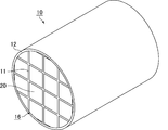
- FIG. FIG. 2 is a perspective view showing a honeycomb structure manufactured by the method for manufacturing a honeycomb structure of the present invention
- Fig. 3 (a) is a perspective view of the honeycomb fired body constituting the honeycomb structure
- Fig. 3 (b) is a cross-sectional view taken along the line AA of the honeycomb fired body shown in Fig. 3 (a). .
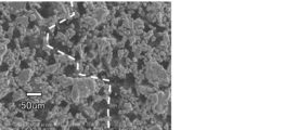
- FIG. 4 is a scanning microscope (SEM) photograph showing a cut surface when a part of the honeycomb fired body manufactured by the method for manufacturing a honeycomb structure of the present invention is cut.
- FIG. 5 is an SEM photograph showing a result of generating cracks in the honeycomb fired body constituting the honeycomb structure manufactured in Example 1 and observing cracked portions.
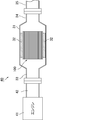
- FIG. 6 is an explanatory view schematically showing an exhaust gas purification device for measuring the regeneration limit value.
- FIG. 7 is an SEM photograph showing a result of generating cracks in the honeycomb fired body constituting the honeycomb structure manufactured in Comparative Example 1 and observing cracked portions.
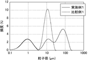
- FIG. 8 is a graph showing the results of determining the particle size distribution of the mixture of silicon carbide particles used in Example 1 and Comparative Example 1 using a laser diffraction particle size distribution measuring apparatus.
- the honeycomb structure manufacturing method of the present invention has a particle size distribution of 0.1 ⁇ m or more and 1.0 ⁇ m or less, a region exceeding 1.0 ⁇ m and 15 ⁇ m or less, and A raw material composition is prepared using ceramic particles having peaks in three regions of more than 15 ⁇ m and not more than 100 ⁇ m, and a honeycomb structure made of porous ceramic is manufactured by performing at least a forming step, a degreasing step and a firing step. It is characterized by that.
- a molded body production process for producing a honeycomb molded body using a degreasing process for degreasing the honeycomb molded body produced by the above-mentioned molded body production process, and a firing process for firing the degreased honeycomb molded body, An adhesion process, a cutting process, and an outer peripheral coat layer forming process that are performed as necessary are also described.
- Raw material composition preparation step In this raw material composition preparation step, an organic binder, a plasticizer, a lubricant, a dispersion medium liquid (water), a pore forming agent, and the like are added to the ceramic particles as necessary, and a kneader or the like. To prepare a raw material composition for the method for producing a molded body.
- Ceramic particle material used in the present invention examples include nitride ceramics such as aluminum nitride, silicon nitride, boron nitride, and titanium nitride, carbide ceramics such as zirconium carbide, titanium carbide, tantalum carbide, and tungsten carbide, and metal and nitride. Ceramic ceramic composites, metal and carbide ceramic composites, and the like, and ceramic particles made of the various materials described above can be used.
- silicon carbide which is excellent in heat resistance and mechanical properties when producing a ceramic, is preferable.
- silicon carbide is mainly used as ceramic particles will be described.
- other types of ceramic particles may be used, and silicon carbide particles and other types of particles may be used. And may be used in combination.
- the particle size distribution when the particle size distribution is measured as the silicon carbide particles based on the laser diffraction method, the particle size distribution is 0.1 ⁇ m or more to 1.0 ⁇ m or less, 1.0 ⁇ m or more to 15 ⁇ m or less, and 15 ⁇ m. Ceramic particles having a peak in three regions of a region exceeding 100 ⁇ m and less are used.
- the particle size distribution measurement device based on the laser diffraction method is that when a particle is irradiated with a laser beam (monochromatic light), diffracted light and scattered light are emitted in various directions depending on the size of the particle. This is a method for determining the particle size by analyzing the diffraction / scattering intensity distribution, and can measure both dry and wet methods.
- the particle size distribution is obtained by a wet process.
- the particle size distribution can be obtained using MASTERSIZER 2000 manufactured by Malvern Instruments.
- the measurement conditions are: sample measurement time: 7 to 10 seconds, background time: 4 seconds, number of measurement cycles: 1 time, PUMP SPEED: 2000 to 2500 rpm, ULTRASONIC DISPLACEMENT: 20.00, ULTRASONIC TIMER: 5 minutes.
- sodium hexametaphosphate is used as a dispersant, and the concentration of ceramic particles is adjusted to 0.02% by weight to obtain a dispersion. And it measures by the following procedures. (1) Stirring of dispersion The dispersion before introducing ceramic particles is ultrasonically stirred for 5 minutes. (2) Various conditions are adjusted by software based on the state of the background dispersion. (3) The ceramic particles are gradually added to the dispersion while stirring the dispersion of ceramic particles for 5 minutes, and the addition is terminated when the scattered light intensity becomes 13 ⁇ 2%. (4) Implementation of measurement Measurement is started for the prepared dispersion containing ceramic particles. (5) Confirmation of measurement result When the measurement is completed, the measurement result is displayed, and the result is confirmed.
- the ceramic has a peak in three regions: a particle size distribution of 0.1 ⁇ m or more and 1.0 ⁇ m or less, a region exceeding 1.0 ⁇ m and 15 ⁇ m or less, and a region exceeding 15 ⁇ m and 100 ⁇ m or less.
- the particle size distribution may be measured using particles, but ceramic particles having a peak in a region of 0.1 ⁇ m or more and 1.0 ⁇ m or less, ceramic particles having a peak in a region of more than 1.0 ⁇ m and 15 ⁇ m or less, and 15 ⁇ m
- the particle size distribution of each of the three types of ceramic particles having a peak in a region exceeding 100 ⁇ m and not exceeding 100 ⁇ m may be obtained.
- the method for obtaining the above-mentioned silicon carbide particles is not particularly limited, but usually, ceramic particles having a peak in the region where the particle size distribution is 0.1 ⁇ m or more and 1.0 ⁇ m or less when measured by the above measurement method (fine Particles), ceramic particles having a peak in the region where the particle size distribution exceeds 1.0 ⁇ m and 15 ⁇ m or less (small particles), and ceramic particles having a peak in the region where the particle size distribution exceeds 15 ⁇ m and 100 ⁇ m or less (large particles) are mixed Thus, ceramic particles having peaks in the above three regions in the particle size distribution can be obtained.
- the large particles are preferably flat silicon carbide particles.
- a honeycomb fired body is manufactured by firing, large flat particles resulting from the flat silicon carbide particles of the raw material are formed in the honeycomb fired body, and when cracks and the like are formed, the cracks bypass the large particles. In doing so, since a large amount of energy is consumed, the extension of cracks is prevented and a honeycomb fired body having excellent mechanical properties is obtained.
- the large particles may be particles made of a material different from silicon carbide such as silicon nitride.
- the weight ratio of the large particles to the total weight of the ceramic particles is preferably 10 to 60% by weight. If the weight ratio of the large particles to the total weight of the silicon carbide particles is less than 10% by weight, the proportion of the large particles is too small, and effectively inhibits the extension of cracks and the like due to heat shock during regeneration. Becomes difficult and the regeneration limit value decreases. On the other hand, when the weight ratio of the large particles with respect to the total weight of the ceramic particles exceeds 60% by weight, the ratio of the large particles is too large, so that the sintering becomes difficult and the mechanical characteristics of the manufactured honeycomb structure are low. It will deteriorate.
- organic binder added to the raw material composition examples include methyl cellulose, carboxymethyl cellulose, hydroxyethyl cellulose, polyethylene glycol, phenol resin, and epoxy resin. Of these, methylcellulose is preferred.
- the dispersion medium liquid examples include alcohols such as methanol, organic solvents such as benzene, and water. It does not specifically limit as said plasticizer, For example, glycerol etc. are mentioned.
- the lubricant is not particularly limited, and examples thereof include polyoxyalkylene compounds such as polyoxyethylene alkyl ether and polyoxypropylene alkyl ether. Specific examples of the lubricant include polyoxyethylene monobutyl ether and polyoxypropylene monobutyl ether.
- pore-forming agent examples include spherical acrylic particles, graphite, and balloons that are fine hollow spheres.
- specific examples of the balloon include silica balloon, glass micro balloon, shirasu balloon, fly ash balloon (FA balloon), mullite balloon and the like. By using such a pore-forming agent, it becomes easy to control the porosity of the manufactured honeycomb structure.
- alumina, alumina, yttria, or the like may be added as a sintering aid.
- a sintering aid By adding the above-mentioned sintering aid, liquid layer sintering is likely to proceed during firing, and a honeycomb structure having more excellent mechanical characteristics can be manufactured.
- the addition amount of the sintering aid is preferably 0.1 to 10.0 parts by weight with respect to 100 parts by weight of the ceramic particles.
- a honeycomb molded body in which a large number of through holes are arranged in parallel in the extrusion direction is manufactured by extruding the prepared raw material composition.
- the obtained raw material composition is put into an extrusion molding machine equipped with a molding die, extruded, and a continuous body is produced, and then cut into a predetermined length in the longitudinal direction.
- a raw honeycomb molded body in which a large number of through holes are arranged in parallel can be produced.
- the raw honeycomb formed body is dried using a microwave dryer, a hot air dryer, a dielectric dryer, a vacuum dryer, a vacuum dryer, a freeze dryer, or the like.
- a microwave dryer and a hot air dryer are used in combination, or the honeycomb formed body is dried to a certain level of moisture using a microwave dryer, and then a hot air dryer is used. Thus, moisture in the honeycomb formed body may be completely removed.
- a predetermined amount of the plug material paste is filled into any one end of the cells constituting the dried honeycomb molded body, and the cells are plugged.
- a cell sealing mask is applied to the end face of the honeycomb formed body (that is, the cut face after cutting both ends), and the sealing material is applied only to the cells that need to be sealed. Fill the paste and dry the encapsulant paste.
- the honeycomb molded body after the sealing step is heated in an oxidizing atmosphere such as air at 300 to 650 ° C. for 0.5 to 3 hours to remove organic matter in the honeycomb molded body. It removes and the defatted body of a honeycomb molded object is produced.
- an oxidizing atmosphere such as air at 300 to 650 ° C. for 0.5 to 3 hours to remove organic matter in the honeycomb molded body. It removes and the defatted body of a honeycomb molded object is produced.
- the honeycomb formed body degreased body obtained in the above degreasing step is fired in an inert gas atmosphere such as a nitrogen atmosphere or an argon atmosphere at 1800 to 2200 ° C. for 0.5 to 4 hours. Quality honeycomb fired bodies are produced.
- an inert gas atmosphere such as a nitrogen atmosphere or an argon atmosphere at 1800 to 2200 ° C. for 0.5 to 4 hours.
- the shape of the manufactured honeycomb fired body is not particularly limited, and may be a rectangular column shape, a cylindrical shape, or a vertical column shape. It can also be used as a body.
- silicon carbide is used as the ceramic particles
- a plurality of manufactured honeycomb fired bodies are bonded through an adhesive layer to produce a honeycomb aggregate, and then a cutting process is performed to produce a honeycomb block having a predetermined shape.
- Adhesion process In this adhesion process, the honeycomb fired body manufactured by the above process is placed on a mounting table having a V-shaped recess, and an adhesive paste is applied to the side surface of the honeycomb fired body. By repeating the procedure of placing another honeycomb fired body on top, a plurality of honeycomb fired bodies are temporarily bonded to each other through an adhesive paste layer, and dried to obtain a plurality of honeycomb fired bodies. A honeycomb aggregate in which is bonded through an adhesive layer is produced.
- a sealing material paste what consists of an inorganic binder, an organic binder, an inorganic fiber, and / or an inorganic particle can be used, for example.
- FIG. 1 (a) is a front view schematically showing an example of the bonding step in the method for manufacturing a honeycomb structure of the present invention
- FIG. 1 (b) schematically shows the honeycomb aggregate produced in the bonding step.
- FIG. 1A the honeycomb fired body 20 manufactured by the above-described process is placed on a mounting table 28 having a V-shaped recess, and the honeycomb fired body 20 is placed on the side surface 20a.
- a temporary bonded assembly in which a plurality of honeycomb fired bodies 20 are temporarily bonded via the adhesive paste layer 11 ′ is obtained.
- a honeycomb aggregate 15 in which a plurality of honeycomb fired bodies 20 are bonded via the adhesive layer 11 as shown in FIG. 1B is manufactured.
- a sealing material paste what consists of an inorganic binder, an organic binder, an inorganic fiber, and / or an inorganic particle can be used, for example.
- the honeycomb aggregate 15 is cut using a diamond cutter or the like to produce, for example, a cylindrical ceramic block.
- Outer peripheral coat layer forming step After applying the outer peripheral coat material paste to the outer peripheral surface of the ceramic block manufactured by the above step, the outer peripheral coat layer is formed by drying and solidifying, thereby manufacturing the honeycomb structure. finish.
- the outer periphery coating material paste can be the same as the adhesive paste.
- honeycomb structure manufactured by the above manufacturing method a plurality of porous honeycomb fired bodies made of silicon carbide are combined through an adhesive layer to form a cylindrical ceramic block, and around the ceramic block.
- the outer peripheral coat layer is formed.
- the honeycomb fired body constituting the honeycomb structure has a quadrangular prism shape, and includes a porous cell partition wall and an outer peripheral wall that form a plurality of cells serving as exhaust gas flow paths, and an end portion on the exhaust gas inlet side. And an exhaust gas introduction cell whose end on the exhaust gas outlet side is plugged, and an exhaust gas discharge cell whose end on the exhaust gas outlet side is open and whose end on the exhaust gas inlet side is plugged.
- the cross section of the exhaust gas introduction cell in the direction perpendicular to the longitudinal direction of the cells of the honeycomb fired body is octagonal, the cross sectional shape of the exhaust gas discharge cell is quadrangular, and the cross sectional area of the exhaust gas introduction cell is It is set larger than the cross-sectional area.
- the cell partition wall separating the exhaust gas introduction cell and the exhaust gas discharge cell functions as a filter
- the exhaust gas has an end on the exhaust gas inlet side and an end on the exhaust gas outlet side. After being sealed and flowing into the exhaust gas introduction cell, it always passes through the cell partition, and flows out from the exhaust gas discharge cell whose end on the exhaust gas outlet side is opened and whose end on the exhaust gas inlet side is plugged.
- the PM in the exhaust gas is deposited on the surface of the cell partition wall, so that the PM is removed and the exhaust gas is purified.
- FIG. 2 is a perspective view showing a honeycomb structure manufactured by the method for manufacturing a honeycomb structure of the present invention.
- Fig. 3 (a) is a perspective view of the honeycomb fired body constituting the honeycomb structure, and Fig. 3 (b) is a cross-sectional view taken along the line AA of the honeycomb fired body shown in Fig. 3 (a). .
- the honeycomb structure 10 includes a plurality of porous honeycomb fired bodies 20 made of silicon carbide combined with an adhesive layer 11 to form a cylindrical ceramic block 16.
- An outer peripheral coat layer 12 is formed around the block 16.
- the honeycomb fired body 20 constituting the honeycomb structure 10 has a quadrangular prism shape, a porous cell partition wall 23 that forms a plurality of cells 21 and 22 that serve as exhaust gas flow paths, and an outer periphery.
- An exhaust gas introduction cell 21 having a wall, an end portion on the exhaust gas inlet side being opened and an end portion on the exhaust gas outlet side being plugged, and an end portion on the exhaust gas outlet side being opened and an end portion on the exhaust gas inlet side being The cross section of the exhaust gas introduction cell 21 in a direction perpendicular to the longitudinal direction of the honeycomb fired body 20 is an octagonal shape, and the cross sectional shape of the exhaust gas exhaust cell 22 is a square.
- the cross-sectional area of the exhaust gas introduction cell 21 is set larger than the cross-sectional area of the exhaust gas discharge cell 22.
- the cell partition wall 23 that separates the exhaust gas introduction cell 21 and the exhaust gas discharge cell 22 functions as a filter, and the exhaust gas is opened at the end on the exhaust gas inlet side and on the exhaust gas outlet side. After the end is plugged and flows into the exhaust gas introduction cell 21, it always passes through the cell partition wall 23, the exhaust gas outlet side end is opened, and the exhaust gas inlet side end is plugged. Spill from. The PM in the exhaust gas is deposited on the surface of the cell partition wall, so that the PM is removed and the exhaust gas is purified.
- FIG. 4 is a scanning microscope (SEM) photograph showing a cut surface when a part of the honeycomb fired body manufactured by the method for manufacturing a honeycomb structure of the present invention is cut
- FIG. It is a SEM photograph which shows the result of having generated the crack in the honeycomb calcination object which constitutes the manufactured honeycomb structure, and observing the crack generating part.
- particles having a peak in the region where the particle size distribution of the raw material is 0.1 ⁇ m or more and 1.0 ⁇ m or less, and the particle size distribution exceeds 1.0 ⁇ m and 15 ⁇ m.
- the regeneration limit value is larger than that of the conventional honeycomb fired body, and even when more PM is deposited, the honeycomb fired body is less likely to be destroyed during regeneration.
- the thickness of the cell partition walls of the honeycomb fired body constituting the honeycomb structure manufactured by the method of the present invention is preferably 0.075 mm to 0.400 mm.
- the permeation resistance of the exhaust gas cell partition wall can be reduced, and the pressure loss can be further reduced. If the cell partition wall thickness is less than 0.075 mm, the cell partition wall thickness becomes too thin, and the mechanical strength of the honeycomb structure decreases. On the other hand, when the thickness of the cell partition wall exceeds 0.400 mm, the cell partition wall becomes thick and pressure loss when exhaust gas permeates the cell partition wall increases.
- the porosity of the cell partition walls is preferably 42 to 70%.
- the porosity of the cell partition wall is 42 to 70%, the cell partition wall can collect PM in the exhaust gas well, and can suppress an increase in pressure loss due to the cell partition wall. Therefore, the honeycomb structure has a low initial pressure loss and is unlikely to increase even when PM is deposited. If the porosity of the cell partition is less than 42%, the ratio of the pores in the cell partition is too small, so that the exhaust gas is difficult to permeate the cell partition, and the pressure loss when the exhaust gas permeates the cell partition increases.
- the porosity of the cell partition wall exceeds 70%, the mechanical properties of the cell partition wall are low, and cracks are likely to occur during regeneration.
- the pore diameter and the porosity are measured by a mercury intrusion method with a contact angle of 130 ° and a surface tension of 485 mN / m.
- the average pore diameter of the pores contained in the cell partition walls is preferably 8 to 25 ⁇ m.
- PM can be collected with high collection efficiency while suppressing an increase in pressure loss. If the average pore diameter of the pores contained in the cell partition walls is less than 8 ⁇ m, the pores are too small, and the pressure loss when the exhaust gas permeates the cell partition walls increases. On the other hand, when the average pore diameter of the pores contained in the cell partition wall exceeds 25 ⁇ m, the pore diameter becomes too large, and the PM collection efficiency is lowered.
- the number of cells per unit area in the cross section perpendicular to the longitudinal direction of the cells of the honeycomb fired body constituting the honeycomb structure manufactured by the method of the present invention is 31 to 62 cells / cm 2 (200 to 400 cells / inch). 2 ) is desirable.
- Example 1 Production of honeycomb fired body First, in the raw material composition preparation step, 25.6% by weight of large particles of silicon carbide having an average particle size of 70 ⁇ m (YB-70 ⁇ m manufactured by Yakushima Electric Works) and an average particle size of 10 ⁇ m Small particles of silicon carbide (GP # 1500, manufactured by Shinano Denki Co., Ltd.) 13.1% by weight and fine particles of silicon carbide having an average particle size of 0.5 ⁇ m (GC-15, manufactured by Yakushima Electric Co., Ltd.) 16.6% %, And organic binder (methylcellulose) 5.7% by weight, lubricant (Unilube made by NOF Corporation) 2.9% by weight, glycerin 1.5% by weight, pore former (Acrylic resin) 11.8 wt%, 2.8 wt% alumina, and 20.0 wt% water were added and kneaded to obtain a raw material composition.
- GP # 1500 manufactured by Shinano Denki Co., Ltd.
- plugging material paste was filled into predetermined cells of the dried honeycomb molded body to plug the cells, thereby obtaining a honeycomb molded body.
- the said raw material composition was used as a sealing material paste in the case of plugging.
- the dried honeycomb molded body filled with the plug paste was again dried using a dryer.
- the plurality of dried honeycomb formed bodies were carried into a degreasing furnace, heated to 400 ° C. in air at normal pressure, and then degreased by stopping the heating. Thereafter, the honeycomb formed body after the degreasing treatment was carried into a firing furnace and subjected to firing treatment under conditions of 2200 ° C. and 3 hours in an atmospheric pressure of argon to produce a honeycomb fired body.
- the obtained honeycomb fired body is made of a porous silicon carbide sintered body, having a porosity of 58.9%, an average pore diameter of 16.5 ⁇ m, a size of 34.3 mm ⁇ 34.3 mm ⁇ 150 mm,
- the number (cell density) was 31 cells / cm 2 (250 cells / inch 2 ), the cell partition wall thickness was 0.3556 mm, and the outer peripheral wall thickness was 0.3 mm.
- honeycomb structure was manufactured using the honeycomb fired body obtained by the above process.
- An aggregate of honeycomb fired bodies is obtained by applying an adhesive paste to a predetermined side surface of the honeycomb fired body 1 and adhering 36 (6 vertical ⁇ 6 horizontal) honeycomb fired bodies via the adhesive paste.
- the aggregate of the honeycomb fired bodies was dried and solidified at 180 ° C. for 20 minutes to produce a prismatic ceramic block having an adhesive layer thickness of 1 mm.
- the cylindrical ceramic block of diameter 198mm was produced by grinding the outer periphery of a prismatic ceramic block using a diamond cutter.
- the outer periphery coating material paste is applied to the outer periphery of the cylindrical ceramic block, and the outer periphery coating material paste is heated and solidified at 120 ° C., thereby forming an outer periphery coating layer having a thickness of 1.0 mm on the outer periphery of the ceramic block. Formed.
- the said adhesive material paste was used as an outer periphery coating material paste.
- extrusion molding was performed using the obtained raw material composition to obtain a raw honeycomb formed body.
- the raw honeycomb formed body was dried using a microwave dryer, thereby manufacturing a dried body of the honeycomb formed body.
- plugging material paste was filled into predetermined cells of the dried honeycomb molded body to plug the cells, thereby obtaining a honeycomb molded body.
- the said raw material composition was used as a sealing material paste in the case of plugging.
- the dried honeycomb molded body filled with the plug paste was again dried using a dryer.
- the plurality of dried honeycomb formed bodies were carried into a degreasing furnace, heated to 400 ° C. in air at normal pressure, and then degreased by stopping the heating. Thereafter, the honeycomb formed body after the degreasing treatment was carried into a firing furnace and subjected to firing treatment under conditions of 2200 ° C. and 3 hours in an atmospheric pressure of argon to produce a honeycomb fired body.
- the obtained honeycomb fired body is composed of a porous silicon carbide sintered body having a porosity of 61.8%, an average pore diameter of 12 ⁇ m, a size of 34.3 mm ⁇ 34.3 mm ⁇ 150 mm, and the number of cells ( The cell density was 31 cells / cm 2 (250 cells / inch 2 ), the cell partition wall thickness was 0.3556 mm, and the outer peripheral wall thickness was 0.3 mm.
- honeycomb structure was produced in the same manner as in Example 1 using the honeycomb fired body obtained by the above-described steps.
- FIG. 8 is a graph showing the measurement result of the particle size distribution.
- the particle size distribution is obtained by adding the measurement results of large particles, small particles, and fine particles according to the blending weight ratio of the mixed raw materials.
- a graph was created.
- a graph of particle size distribution was created by adding the coarse particle and fine particle measurement results in accordance with the blending weight ratio of the mixed raw materials.
- the particles of Example 1 had a particle size distribution of 0.1 ⁇ m or more and 1.0 ⁇ m or less, a region exceeding 1.0 ⁇ m and 15 ⁇ m or less, and a particle size distribution exceeding 15 ⁇ m and 100 ⁇ m as set.
- Each of the following regions has a peak
- the particles of Comparative Example 1 each have a peak in the region having a particle size distribution of 0.1 ⁇ m to 1.0 ⁇ m and in the region of 1.0 to 15 ⁇ m. It was.
- Tables 1 and 2 show data on the particle size distribution measurement results of Example 1 and Comparative Example 1.
- FIG. 6 is an explanatory view schematically showing an exhaust gas purification device for measuring the regeneration limit value.
- a honeycomb structure 100 is arranged inside a metal casing 31 through a mat 32 made of inorganic fibers, and the casing 41 is placed in an exhaust passage 42 of an engine 41.
- the exhaust gas purifying apparatus has a structure in which an exhaust gas inlet side pipe 33 is connected and a pipe 35 for discharging exhaust gas to the outside is connected to the exhaust gas outlet side pipe 34.
- the honeycomb fired bodies according to Example 1 and Comparative Example 1 constituting the honeycomb structure were arranged in the exhaust gas purification apparatus, and the regeneration limit value was measured. did. Since the honeycomb structure is a collection of a plurality of honeycomb fired bodies, the characteristics of the honeycomb structure can be determined by measuring the regeneration limit value using the honeycomb fired bodies constituting the honeycomb structure. Because.
- the honeycomb fired body according to the example or the comparative example is arranged in the casing 31 via the mat 32, and the engine is operated at a rotational speed of 3000 min ⁇ 1 and a torque of 50 Nm for a predetermined time.
- a fixed amount of particulate was collected.
- the particulate matter (PM) is forcibly burned by setting the engine speed to 1050 min ⁇ 1 and torque 30 Nm.
- Reproduction processing to perform was performed. And experiment which performs this reproduction
- the regeneration limit value was 9.0 g / L, whereas in the honeycomb fired body according to Comparative Example 1, it was 6.9 g / L. It was revealed that the regeneration limit value of the honeycomb fired body according to Example 1 in which large particles were added as silicon carbide particles was greatly improved.
- g / L is the amount of PM deposited per unit volume of the honeycomb fired body, and the unit volume is a unit volume including cells, cell partition walls, and outer peripheral walls of the honeycomb fired body.
- FIG. 5 shows a crack occurrence portion of the honeycomb fired body according to Example 1, in which cracks are not formed linearly, but cracks having a greatly bent shape are observed so as to bypass large particles.
- FIG. 7 is an SEM photograph showing the result of observing the cracked portion by generating cracks in the honeycomb fired body used in Comparative Example 1. As is clear from FIG. 7, no large particles are observed in the honeycomb fired body, and cracks are formed in a shape closer to a straight line as compared with the honeycomb fired body of Example 1.
Landscapes
- Chemical & Material Sciences (AREA)
- Engineering & Computer Science (AREA)
- Ceramic Engineering (AREA)
- Materials Engineering (AREA)
- Structural Engineering (AREA)
- Organic Chemistry (AREA)
- Manufacturing & Machinery (AREA)
- Filtering Materials (AREA)
- Filtering Of Dispersed Particles In Gases (AREA)
- Porous Artificial Stone Or Porous Ceramic Products (AREA)
Abstract
本発明のハニカム構造体の製造方法は、レーザー回折法に基づいて粒度分布を測定した際、粒度分布が0.1μm以上1.0μm以下の領域、1.0μmを超え15μm以下の領域、及び、15μmを超え100μm以下の領域の3つの領域にピークを有するセラミック粒子を用いて原料組成物を調製し、少なくとも成形工程、脱脂工程及び焼成工程を行って多孔質セラミックからなるハニカム構造体を製造することを特徴とする。
Description
本発明は、ハニカム構造体の製造方法に関する。
ディーゼルエンジン等の内燃機関から排出される排ガス中には、スス等のパティキュレート(以下、PMともいう)が含まれており、近年、このPMが環境または人体に害を及ぼすことが問題となっている。また、排ガス中には、CO、HCまたはNOx等の有害なガス成分も含まれていることから、この有害なガス成分が環境または人体に及ぼす影響についても懸念されている。
そこで、内燃機関と連結されることにより排ガス中のPMを捕集したり、排ガスに含まれるCO、HCまたはNOx等の排ガス中の有害なガス成分を浄化したりする排ガス浄化装置として、コージェライトや炭化ケイ素等の多孔質セラミックからなるハニカム構造体が種々提案されている。
ハニカム構造体は、排ガスの流路となる複数のセルを区画形成する多孔質のセル隔壁を備えるとともに、排ガス入口側の端部が開口され且つ排ガス出口側の端部が目封止された排ガス導入セルと、排ガス出口側の端部が開口され且つ排ガス入口側の端部が目封止された排ガス排出セルとを備えており、ハニカム構造体に流入した排ガス中のPMは、セル隔壁に捕集され、排ガスが浄化される(特許文献1)。
また、これらのハニカム構造体では、フィルタとして使用する際の内燃機関の燃費を改善し、圧力損失の上昇に起因する運転時のトラブル等をなくすために、圧力損失がより低いハニカム構造体が求められており、そのために、セル隔壁の気孔率を上げたり、セル隔壁を薄くすることが求められている。
以下、本明細書において、単に、セルと記載した場合は、排ガス排出セル及び排ガス導入セルの両方を指す。
さらに、排ガス導入セル及び排ガス排出セルのセルの長手方向に対して垂直方向の断面を、単に、排ガス導入セル、排ガス排出セルの断面と表記する場合がある。
しかしながら、セル隔壁の気孔率が上昇したり、セル隔壁が薄くなるにともない、多孔質セラミックからなるセル隔壁の機械的特性が低下し易く、再生時にクラック等が発生し易くなるという問題がある。従って、再生時の熱ショック等に耐え、クラックの伝搬を阻止し、ハニカム構造体の機械的特性を改善することが求められている。
本発明者らは、上記課題に鑑み、鋭意検討した結果、機械的特性を改善するとともに、クラック等の伝搬を阻止することが可能なハニカム構造体を製造するには、粒径が15μm以下の2種類の大きさの異なる粒子に加え、さらに粒径の大きい粒子を加えてハニカム構造体を製造することにより、大きい粒子がクラックの伝搬を防止し、機械的特性が改善されることを見出し、本発明に到達したものである。
すなわち、本発明のハニカム構造体の製造方法は、レーザー回折法に基づいて粒度分布を測定した際、粒度分布が0.1μm以上1.0μm以下の領域、1.0μmを超え15μm以下の領域、及び、15μmを超え100μm以下の領域の3つの領域にピークを有するセラミック粒子を用いて原料組成物を調製し、少なくとも成形工程、脱脂工程及び焼成工程を行って多孔質セラミックからなるハニカム構造体を製造することを特徴とする。
以下においては、粒度分布が0.1μm以上1.0μm以下の領域にピークを有するセラミック粒子を「微小粒子」、粒度分布が1.0μmを超え15μm以下の領域にピークを有するセラミック粒子を「小粒子」、粒度分布が15μmを超え100μm以下の領域にピークを有するセラミック粒子を「大粒子」という場合がある。
上記ハニカム構造体の製造方法では、粒度分布が15μmを超え100μm以下の領域にピークを有する大粒子が原料組成物中に含有されており、製造されたハニカム構造体を構成するハニカム焼成体中に原料の大粒子に起因する大きな粒子が存在することにより、PMを除去するフィルタとして使用した場合、再生等の熱ショックによるクラック等の伸展が阻害されるため、機械的特性に優れ、再生限界値の大きなハニカム構造体を製造することができる。
上記ハニカム構造体の製造方法においては、レーザー回折法に基づいて粒度分布を測定した際、粒度分布が0.1μm以上1.0μm以下の領域にピークを有するセラミック粒子、粒度分布が1.0μmを超え15μm以下の領域にピークを有するセラミック粒子、及び、粒度分布が15μmを超え100μm以下の領域にピークを有する3種類のセラミック粒子を混合したものを用いて原料組成物を調製することが望ましい。
上記ハニカム構造体の製造方法で、上記した3種類の粒度分布が異なる粒子を使用した場合、サイズ毎にセラミック粒子の組成や粒子形状等の諸特性を変えることができ、これにより製造するハニカム構造体の機械的特性を制御することが可能となる。
本発明のハニカム構造体の製造方法においては、15μmを超え100μm以下の領域にピークを有するセラミック粒子は、扁平形状のセラミック粒子からなることが望ましい。
上記ハニカム構造体の製造方法では、製造されたハニカム構造体中に原料の扁平形状の大粒子に起因する大きな扁平形状の粒子が存在することにより、再生等に起因する熱ショックによるクラック等の伸展がより効果的に阻害されるため、機械的特性に優れ、再生限界値のより大きなハニカム構造体を製造することができる。
上記ハニカム構造体の製造方法では、製造されたハニカム構造体中に原料の扁平形状の大粒子に起因する大きな扁平形状の粒子が存在することにより、再生等に起因する熱ショックによるクラック等の伸展がより効果的に阻害されるため、機械的特性に優れ、再生限界値のより大きなハニカム構造体を製造することができる。
本発明のハニカム構造体の製造方法においては、15μmを超え100μm以下の領域にピークを有するセラミック粒子(大粒子)の上記セラミック粒子全体の重量に対する重量割合は、10~60重量%であることが望ましい。
上記ハニカム構造体の製造方法では、上記大粒子の上記セラミック粒子全体の重量に対する重量割合が、10~60重量%であると、大粒子が焼結の邪魔とならず、焼結も良好に進行し、機械的特性に優れ、再生限界値のより大きなハニカム構造体を製造することができる。
上記ハニカム構造体の製造方法では、上記大粒子の上記セラミック粒子全体の重量に対する重量割合が、10~60重量%であると、大粒子が焼結の邪魔とならず、焼結も良好に進行し、機械的特性に優れ、再生限界値のより大きなハニカム構造体を製造することができる。
上記大粒子の上記セラミック粒子全体の重量に対する重量割合が10重量%未満であると、上記大粒子の割合が少なすぎるため、再生中の熱ショックによるクラック等の伸展を効果的に阻害することが難しくなり、再生限界値が低下する。
一方、上記大粒子の上記セラミック粒子全体の重量に対する重量割合が60重量%を超えると、上記大粒子の割合が多すぎるため、焼結が難しくなり、製造されるハニカム構造体の機械的特性が劣化してしまう。
一方、上記大粒子の上記セラミック粒子全体の重量に対する重量割合が60重量%を超えると、上記大粒子の割合が多すぎるため、焼結が難しくなり、製造されるハニカム構造体の機械的特性が劣化してしまう。
本発明のハニカム構造体の製造方法においては、原料組成物を調製する際、焼結助剤としてアルミナ又はアルミナとイットリアとを添加することが望ましい。
上記ハニカム構造体の製造方法では、焼結助剤としてアルミナ又はアルミナとイットリアとが添加された原料組成物を用いると、焼成時に液層焼結が進行し易くなり、より機械的特性に優れたハニカム構造体を製造することができる。
上記ハニカム構造体の製造方法では、焼結助剤としてアルミナ又はアルミナとイットリアとが添加された原料組成物を用いると、焼成時に液層焼結が進行し易くなり、より機械的特性に優れたハニカム構造体を製造することができる。
本発明のハニカム構造体の製造方法においては、製造されるハニカム構造体の気孔率は、42~70%であることが望ましい。
製造されるハニカム構造体の気孔率が42~70%であると、圧力損失が低く、かつ、機械的特性に優れたハニカム構造体を製造することができる。
製造されるハニカム構造体の気孔率が42~70%であると、圧力損失が低く、かつ、機械的特性に優れたハニカム構造体を製造することができる。
製造されるハニカム構造体の気孔率が42%未満であると、ハニカム構造体の気孔率が小さすぎるため、初期の圧力損失も大きくなり、少量のPMが堆積しても、圧力損失が上昇し易くなる。
一方、製造されるハニカム構造体の気孔率が70%を超えると、ハニカム構造体の気孔率が大きすぎるため、PMが気孔を通過しやすくなり、PMの捕集率が低下するとともに、ハニカム構造体の機械的特性が劣化する。
一方、製造されるハニカム構造体の気孔率が70%を超えると、ハニカム構造体の気孔率が大きすぎるため、PMが気孔を通過しやすくなり、PMの捕集率が低下するとともに、ハニカム構造体の機械的特性が劣化する。
本発明のハニカム構造体の製造方法においては、原料組成物を調製する際、球状アクリル粒子、でんぷん、グラファイト、微小中空球体からなるバルーンよりなる群から選択される少なくとも1種からなる造孔剤を添加することが望ましい。
上記ハニカム構造体の製造方法においては、上記した造孔剤を原料組成物に添加すると、焼成処理中に球状アクリル粒子等の造孔剤が燃焼、焼失して気孔となるか、又は、上記バルーンに起因する気孔がハニカム構造体中に形成されるので、比較的容易に多孔質のハニカム構造体を製造することができる。
上記ハニカム構造体の製造方法においては、上記した造孔剤を原料組成物に添加すると、焼成処理中に球状アクリル粒子等の造孔剤が燃焼、焼失して気孔となるか、又は、上記バルーンに起因する気孔がハニカム構造体中に形成されるので、比較的容易に多孔質のハニカム構造体を製造することができる。
本発明のハニカム構造体の製造方法においては、上記セラミック粒子は、炭化ケイ素、窒化ケイ素、炭化チタン、炭化タングステン、炭化モリブデン、炭化タンタル、炭化ニオブ、炭化バナジウム、炭化ジルコニウム、窒化チタン、窒化タンタル窒化ニオブ、窒化バナジウム、窒化ジルコニウムからなる群から選択される少なくとも1種であることが望ましい。
上記ハニカム構造体の製造方法では、上記セラミック粒子は、炭化ケイ素、窒化ケイ素、炭化チタン、炭化タングステン、炭化モリブデン、炭化タンタル、炭化ニオブ、炭化バナジウム、炭化ジルコニウム、窒化チタン、窒化タンタル窒化ニオブ、窒化バナジウム、窒化ジルコニウムからなる群から選択される少なくとも1種であると、耐熱性、機械的特性に優れたハニカム構造体を製造することができる。
上記ハニカム構造体の製造方法では、上記セラミック粒子は、炭化ケイ素、窒化ケイ素、炭化チタン、炭化タングステン、炭化モリブデン、炭化タンタル、炭化ニオブ、炭化バナジウム、炭化ジルコニウム、窒化チタン、窒化タンタル窒化ニオブ、窒化バナジウム、窒化ジルコニウムからなる群から選択される少なくとも1種であると、耐熱性、機械的特性に優れたハニカム構造体を製造することができる。
本発明のハニカム構造体の製造方法においては、製造されるハニカム構造体は、排ガスの流路となる複数のセルを区画形成する多孔質のセル隔壁を備えるとともに、排ガス入口側の端部が開口され且つ排ガス出口側の端部が目封止された排ガス導入セルと、排ガス出口側の端部が開口され且つ排ガス入口側の端部が目封止された排ガス排出セルとを備えており、上記ハニカム構造体のセルの長手方向に垂直な方向における排ガス導入セルの断面は八角形状であり、排ガス排出セルの断面形状は四角形状であり、上記排ガス導入セルの上記断面積は、上記排ガス排出セルの断面積より大きいことが望ましい。
上記ハニカム構造体の製造方法では、製造されるハニカム構造体が上記した構成のハニカム構造体であると、フィルタとして充分な性能を有するハニカム構造体となる。
上記ハニカム構造体の製造方法では、製造されるハニカム構造体が上記した構成のハニカム構造体であると、フィルタとして充分な性能を有するハニカム構造体となる。
(発明の詳細な説明)
以下、本発明のハニカム構造体の製造方法について説明する。
本発明のハニカム構造体の製造方法は、レーザー回折法に基づいて粒度分布を測定した際、粒度分布が0.1μm以上1.0μm以下の領域、1.0μmを超え15μm以下の領域、及び、15μmを超え100μm以下の領域の3つの領域にピークを有するセラミック粒子を用いて原料組成物を調製し、少なくとも成形工程、脱脂工程及び焼成工程を行って多孔質セラミックからなるハニカム構造体を製造することを特徴とする。
以下、本発明のハニカム構造体の製造方法について説明する。
本発明のハニカム構造体の製造方法は、レーザー回折法に基づいて粒度分布を測定した際、粒度分布が0.1μm以上1.0μm以下の領域、1.0μmを超え15μm以下の領域、及び、15μmを超え100μm以下の領域の3つの領域にピークを有するセラミック粒子を用いて原料組成物を調製し、少なくとも成形工程、脱脂工程及び焼成工程を行って多孔質セラミックからなるハニカム構造体を製造することを特徴とする。
本発明のハニカム構造体の製造方法では、主に、粒度分布が上記した3つの領域にピークを有するセラミック粒子を用いて原料組成物を調製する原料組成物調製工程、調製された原料組成物を用いてハニカム成形体を作製する成形体作製工程、上記成形体作製工程により作製されたハニカム成形体を脱脂する脱脂工程、及び、脱脂されたハニカム成形体を焼成する焼成工程について説明し、その後、必要により行われる接着工程、切削加工工程及び外周コート層形成工程についても説明する。
(1)原料組成物調製工程
この原料組成物調製工程では、上記したセラミック粒子に、必要により有機バインダ、可塑剤、潤滑剤、分散媒液(水)、造孔剤等を添加し、ニーダー等により混合して成形体製造法の原料組成物を調製する。
この原料組成物調製工程では、上記したセラミック粒子に、必要により有機バインダ、可塑剤、潤滑剤、分散媒液(水)、造孔剤等を添加し、ニーダー等により混合して成形体製造法の原料組成物を調製する。
本発明で用いられるセラミック粒子の材料としては、例えば、窒化アルミニウム、窒化ケイ素、窒化ホウ素、窒化チタン等の窒化物セラミック、炭化ジルコニウム、炭化チタン、炭化タンタル、炭化タングステン等の炭化物セラミック、金属と窒化物セラミックの複合体、金属と炭化物セラミックの複合体等が挙げられ、上記した種々の材料からなるセラミック粒子を使用することができる。
これらのなかでは、セラミックを製造した際、耐熱性、機械的特性に優れる炭化ケイ素が好ましい。以下においては、主に、セラミック粒子として炭化ケイ素を使用した場合について説明するが、原料組成物調製の際、他の種類のセラミック粒子を使用してもよく、炭化ケイ素粒子と他の種類の粒子と組み合わせて用いてもよい。
本発明では、炭化ケイ素粒子として、レーザー回折法に基づいて粒度分布を測定した際、粒度分布が0.1μm以上1.0μm以下の領域、1.0μmを超え15μm以下の領域、及び、15μmを超え100μm以下の領域の3つの領域にピークを有するセラミック粒子を使用する。
レーザー回折法に基づく粒度分布測定装置とは、粒子にレーザービーム(単色光)を照射すると、その粒子の大きさに応じて様々な方向へ回折光、散乱光が発せられるが、これらの光の回折・散乱強度分布を解析して粒子径を求める方法であり、乾式と湿式の両方が測定可能である。本発明においては、湿式により粒度分布を求める。本発明には、例えば、Malvern Instruments 社製のMASTERSIZER 2000を用いて粒度分布を求めることができる。
測定条件は、サンプル測定時間:7~10秒間、バックグラウンド時間:4秒間、測定サイクル数:1回、PUMP SPEED:2000~2500rpm、ULTRASONIC DISPLACEMENT:20.00、ULTRASONIC TIMER:5分間である。
粒度分布を測定する際には、分散剤としてヘキサメタリン酸ナトリウムを用い、セラミック粒子の濃度が0.02重量%となる様に調製し、分散液とする。
そして、以下の手順により測定を行う。
(1)分散液の撹拌
セラミック粒子を投入する前の分散液を5分間超音波撹拌する。
(2)バックグラウンドの実施
分散液の状態などから各種条件がソフトウェアにより調整される。
(3)セラミック粒子の投入
分散液を5分間撹拌しながらセラミック粒子を少しずつ分散液に投入し、散乱光強度が13±2%となったら投入を終了する。
(4)測定の実施
調製されたセラミック粒子入り分散液について測定を開始する。
(5)測定結果の確認
測定が終了すると測定結果が表示されるので、その結果を確認する。
そして、以下の手順により測定を行う。
(1)分散液の撹拌
セラミック粒子を投入する前の分散液を5分間超音波撹拌する。
(2)バックグラウンドの実施
分散液の状態などから各種条件がソフトウェアにより調整される。
(3)セラミック粒子の投入
分散液を5分間撹拌しながらセラミック粒子を少しずつ分散液に投入し、散乱光強度が13±2%となったら投入を終了する。
(4)測定の実施
調製されたセラミック粒子入り分散液について測定を開始する。
(5)測定結果の確認
測定が終了すると測定結果が表示されるので、その結果を確認する。
上記粒度分布の測定の際、粒度分布が0.1μm以上1.0μm以下の領域、1.0μmを超え15μm以下の領域、及び、15μmを超え100μm以下の領域の3つの領域にピークを有するセラミック粒子を用いて粒度分布を測定してもよいが、0.1μm以上1.0μm以下の領域にピークを有するセラミック粒子、1.0μmを超え15μm以下の領域にピークを有するセラミック粒子、及び、15μmを超え100μm以下の領域にピークを有するセラミック粒子の3種類のセラミック粒子のそれぞれの粒度分布を求めてもよい。
上記した炭化ケイ素粒子を得る方法は特に限定されるものではないが、通常は、上記測定法により測定した際、粒度分布が0.1μm以上1.0μm以下の領域にピークを有するセラミック粒子(微小粒子)、粒度分布が1.0μmを超え15μm以下の領域にピークを有するセラミック粒子(小粒子)、及び、粒度分布が15μmを超え100μm以下の領域にピークを有するセラミック粒子(大粒子)を混合することにより、粒度分布において、上記した3つの領域にピークを有するセラミック粒子を得ることができる。
上記した3種類の粒度分布が異なる粒子を使用した場合、サイズ毎にセラミック粒子の組成や粒子形状等の諸特性を変えることができ、これにより製造するハニカム構造体の機械的特性を制御することが可能となる。
大粒子は、扁平形状の炭化ケイ素粒子が好ましい。焼成によりハニカム焼成体を製造した際、ハニカム焼成体中に原料の扁平形状の炭化ケイ素粒子に起因する大きな扁平形状の粒子が形成され、クラック等が形成される際、クラックがこの大きな粒子を迂回していく際に、大きなエネルギーが消費されるため、クラックの伸展が阻止され、機械的特性に優れたハニカム焼成体となる。
大粒子は、窒化ケイ素等の炭化ケイ素とは異なる種類の材料からなる粒子であってもよい。
大粒子のセラミック粒子全体の重量に対する重量割合は、10~60重量%であることが好ましい。
上記大粒子の上記炭化ケイ素粒子全体の重量に対する重量割合が10重量%未満であると、上記大粒子の割合が少なすぎるため、再生中の熱ショックによるクラック等の伸展を効果的に阻害することが難しくなり、再生限界値が低下する。
一方、上記大粒子の上記セラミック粒子全体の重量に対する重量割合が60重量%を超えると、上記大粒子の割合が多すぎるため、焼結が難しくなり、製造されるハニカム構造体の機械的特性が劣化してしまう。
上記大粒子の上記炭化ケイ素粒子全体の重量に対する重量割合が10重量%未満であると、上記大粒子の割合が少なすぎるため、再生中の熱ショックによるクラック等の伸展を効果的に阻害することが難しくなり、再生限界値が低下する。
一方、上記大粒子の上記セラミック粒子全体の重量に対する重量割合が60重量%を超えると、上記大粒子の割合が多すぎるため、焼結が難しくなり、製造されるハニカム構造体の機械的特性が劣化してしまう。
原料組成物に添加する有機バインダとしては、例えば、メチルセルロース、カルボキシメチルセルロース、ヒドロキシエチルセルロース、ポリエチレングリコール、フェノール樹脂、エポキシ樹脂等が挙げられる。これらのなかでは、メチルセルロースが好ましい。
上記分散媒液としては、例えば、メタノール等のアルコール、ベンゼン等の有機溶媒が挙げられるほか、水が挙げられる。
上記可塑剤としては特に限定されず、例えば、グリセリン等が挙げられる。
上記可塑剤としては特に限定されず、例えば、グリセリン等が挙げられる。
上記潤滑剤としては特に限定されず、例えば、ポリオキシエチレンアルキルエーテル、ポリオキシプロピレンアルキルエーテル等のポリオキシアルキレン系化合物等が挙げられる。上記潤滑剤の具体例としては、例えば、ポリオキシエチレンモノブチルエーテル、ポリオキシプロピレンモノブチルエーテル等が挙げられる。
上記造孔剤としては、球状アクリル粒子、グラファイト、微小中空球体であるバルーン等が挙げられる。バルーンの具体例としては、例えば、シリカバルーン、ガラスマイクロバルーン、シラスバルーン、フライアッシュバルーン(FAバルーン)、ムライトバルーン等が挙げられる。このような造孔剤を使用することにより、製造されるハニカム構造体の気孔率を制御し易くなる。
上記した原料組成物を調製する際、焼結助剤としてアルミナ、アルミナとイットリア等を添加してもよい。上記した焼結助剤を添加することにより、焼成時に液層焼結が進行し易くなり、より機械的特性に優れたハニカム構造体を製造することができる。
焼結助剤の添加量は、セラミック粒子100重量部に対し、0.1~10.0重量部が好ましい。
焼結助剤の添加量は、セラミック粒子100重量部に対し、0.1~10.0重量部が好ましい。
(2)成形体作製工程
この成形体作製工程では、調製した原料組成物を押出成形することにより、多数の貫通孔が押出方向に並設されたハニカム成形体を作製する。
この工程では、得られた原料組成物を成形金型を備えた押出成形機に投入して、押出成形を行い、連続体を作製した後、所定の長さに切断することにより、長手方向に多数の貫通孔が並設された生のハニカム成形体を作製することができる。
次に、この生のハニカム成形体を、マイクロ波乾燥機、熱風乾燥機、誘電乾燥機、減圧乾燥機、真空乾燥機、又は、凍結乾燥機等を用いて乾燥させる。ハニカム成形体の乾燥では、マイクロ波乾燥機と熱風乾燥機とを併用するか、又は、マイクロ波乾燥機を用いてハニカム成形体をある程度の水分となるまで乾燥させた後、熱風乾燥機を用いてハニカム成形体中の水分を完全に除去してもよい。
次いで、ハニカム成形体の乾燥体を構成するセルのいずれかの端部に、封止材ペーストを所定量充填し、セルを目封止する。セルを目封止する際には、例えば、ハニカム成形体の端面(すなわち両端を切断した後の切断面)にセル封止用のマスクを当てて、封止の必要なセルにのみ封止材ペーストを充填し、封止材ペーストを乾燥させる。このような工程を経て、セルの一端部が目封止されたハニカム成形体を作製することができる。
(3)脱脂工程
次に、上記封止工程後のハニカム成形体を、空気等の酸化性雰囲気中、300~650℃で、0.5~3時間加熱することによりハニカム成形体中の有機物を除去し、ハニカム成形体の脱脂体を作製する。
次に、上記封止工程後のハニカム成形体を、空気等の酸化性雰囲気中、300~650℃で、0.5~3時間加熱することによりハニカム成形体中の有機物を除去し、ハニカム成形体の脱脂体を作製する。
(4)焼成工程
上記脱脂工程で得られたハニカム成形体の脱脂体を窒素雰囲気、アルゴン雰囲気等の不活性ガス雰囲気下で、1800~2200℃、0.5~4時間焼成することにより、多孔質のハニカム焼成体を製造する。
上記脱脂工程で得られたハニカム成形体の脱脂体を窒素雰囲気、アルゴン雰囲気等の不活性ガス雰囲気下で、1800~2200℃、0.5~4時間焼成することにより、多孔質のハニカム焼成体を製造する。
製造されるハニカム焼成体の形状は、特に限定されるものではなく、四角柱形状のほか、円柱形状であってもよく、堕円柱形状であってもよく、製造したハニカム焼成体をそのままハニカム構造体として用いることもできる。しかし、炭化ケイ素をセラミック粒子として用いた場合、製造した複数のハニカム焼成体を接着材層を介して接着し、ハニカム集合体を作製した後、切削加工を施し、所定形状のハニカムブロックを作製し、外周に外周コート層を形成してハニカム構造体を製造する方法をとることが好ましい。セラミック粒子として、炭化ケイ素粒子を使用した場合、ハニカムフィルタとして使用が可能な充分な大きさのハニカム焼成体を製造することが難しいからである。
そこで、以下に、接着工程、切削加工工程及び外周コート層形成工程についても説明する。
そこで、以下に、接着工程、切削加工工程及び外周コート層形成工程についても説明する。
(5)接着工程
この接着工程では、V字形状の凹部を有する載置台に、上記工程により製造されたハニカム焼成体を載置し、ハニカム焼成体の側面に、接着材ペーストを塗布し、その上に別のハニカム焼成体を載置する手順を繰り返し、複数のハニカム焼成体が接着材ペースト層を介して仮接着された仮接着集合体を作製し、乾燥させることにより、複数のハニカム焼成体が接着材層を介して接着されたハニカム集合体を作製する。
なお、シール材ペーストとしては、例えば、無機バインダと有機バインダと無機繊維及び/又は無機粒子とからなるものを使用することができる。
この接着工程では、V字形状の凹部を有する載置台に、上記工程により製造されたハニカム焼成体を載置し、ハニカム焼成体の側面に、接着材ペーストを塗布し、その上に別のハニカム焼成体を載置する手順を繰り返し、複数のハニカム焼成体が接着材ペースト層を介して仮接着された仮接着集合体を作製し、乾燥させることにより、複数のハニカム焼成体が接着材層を介して接着されたハニカム集合体を作製する。
なお、シール材ペーストとしては、例えば、無機バインダと有機バインダと無機繊維及び/又は無機粒子とからなるものを使用することができる。
次に、図面を用いて、(5)接着工程をより詳細に説明する。
図1(a)は、本発明のハニカム構造体の製造方法における接着工程の一例を模式的に示す正面図であり、図1(b)は、接着工程で作製したハニカム集合体を模式的に示す正面図である。
この接着工程では、図1(a)に示すように、V字形状の凹部を有する載置台28に、上記工程により製造されたハニカム焼成体20を載置し、ハニカム焼成体20の側面20aに、接着材ペーストを塗布し、その上に別のハニカム焼成体20を載置する手順を繰り返し、複数のハニカム焼成体20が接着材ペースト層11’を介して仮接着された仮接着集合体を作製し、乾燥させることにより、図1(b)に示すように、複数のハニカム焼成体20が接着材層11を介して接着されたハニカム集合体15を作製する。
なお、シール材ペーストとしては、例えば、無機バインダと有機バインダと無機繊維及び/又は無機粒子とからなるものを使用することができる。
(6)切削加工工程
その後、ダイヤモンドカッター等を用いてハニカム集合体15に切削加工を施し、例えば、円柱形状のセラミックブロックを作製する。
その後、ダイヤモンドカッター等を用いてハニカム集合体15に切削加工を施し、例えば、円柱形状のセラミックブロックを作製する。
(7)外周コート層形成工程
上記工程により作製されたセラミックブロックの外周面に外周コート材ペーストを塗布した後、乾燥固化させて外周コート層を形成することにより、ハニカム構造体を製造の製造を終了する。外周コート材ペーストは、接着材ペーストと同じものを使用することができる。
上記工程により作製されたセラミックブロックの外周面に外周コート材ペーストを塗布した後、乾燥固化させて外周コート層を形成することにより、ハニカム構造体を製造の製造を終了する。外周コート材ペーストは、接着材ペーストと同じものを使用することができる。
上記製造方法により製造されたハニカム構造体は、炭化珪素からなる多孔質のハニカム焼成体が、接着剤層を介して複数個組み合わされて円柱状のセラミックブロックを構成し、このセラミックブロックの周囲に外周コート層が形成された構造をなしている。
具体的な構造の一例は、以下のようなものである。
すなわち、ハニカム構造体を構成するハニカム焼成体は、四角柱形状であり、排ガスの流路となる複数のセルを区画形成する多孔質のセル隔壁及び外周壁を備えるとともに、排ガス入口側の端部が開口され且つ排ガス出口側の端部が目封止された排ガス導入セルと、排ガス出口側の端部が開口され且つ排ガス入口側の端部が目封止された排ガス排出セルとを備えており、ハニカム焼成体のセルの長手方向に垂直な方向における排ガス導入セルの断面は八角形状であり、排ガス排出セルの断面形状は四角形状であり、排ガス導入セルの断面積は、排ガス排出セルの断面積より大きく設定されている。
すなわち、ハニカム構造体を構成するハニカム焼成体は、四角柱形状であり、排ガスの流路となる複数のセルを区画形成する多孔質のセル隔壁及び外周壁を備えるとともに、排ガス入口側の端部が開口され且つ排ガス出口側の端部が目封止された排ガス導入セルと、排ガス出口側の端部が開口され且つ排ガス入口側の端部が目封止された排ガス排出セルとを備えており、ハニカム焼成体のセルの長手方向に垂直な方向における排ガス導入セルの断面は八角形状であり、排ガス排出セルの断面形状は四角形状であり、排ガス導入セルの断面積は、排ガス排出セルの断面積より大きく設定されている。
上記のように構成されたハニカム焼成体では、排ガス導入セル及び排ガス排出セルを隔てるセル隔壁はフィルタとして機能し、排ガスは、排ガス入口側の端部が開口され且つ排ガス出口側の端部が目封止され排ガス導入セルに流入した後、必ずセル隔壁を通過し、排ガス出口側の端部が開口され且つ排ガス入口側の端部が目封止された排ガス排出セルから流出する。排気ガス中のPMがセル隔壁の表面に堆積することによりPMが除去され、排気ガスが浄化される。
上記ハニカム構造体の具合的な構造を図面を用いて説明する。
図2は、本発明のハニカム構造体の製造方法により製造されたハニカム構造体を示す斜視図である。図3(a)は、上記ハニカム構造体を構成するハニカム焼成体の斜視図であり、図3(b)は、図3(a)に示したハニカム焼成体のA-A線断面図である。
図2は、本発明のハニカム構造体の製造方法により製造されたハニカム構造体を示す斜視図である。図3(a)は、上記ハニカム構造体を構成するハニカム焼成体の斜視図であり、図3(b)は、図3(a)に示したハニカム焼成体のA-A線断面図である。
図2に示すように、ハニカム構造体10は、炭化珪素からなる多孔質のハニカム焼成体20が、接着剤層11を介して複数個組み合わされて円柱状のセラミックブロック16を構成し、このセラミックブロック16の周囲に外周コート層12が形成されている。
図3に示すように、ハニカム構造体10を構成するハニカム焼成体20は、四角柱形状であり、排ガスの流路となる複数のセル21、22を区画形成する多孔質のセル隔壁23及び外周壁を備えるとともに、排ガス入口側の端部が開口され且つ排ガス出口側の端部が目封止された排ガス導入セル21と、排ガス出口側の端部が開口され且つ排ガス入口側の端部が目封止された排ガス排出セル22とを備えており、ハニカム焼成体20のセルの長手方向に垂直な方向における排ガス導入セル21の断面は八角形状であり、排ガス排出セル22の断面形状は四角形状であり、排ガス導入セル21の断面積は、排ガス排出セル22の断面積より大きく設定されている。
上記のように構成されたハニカム焼成体20では、排ガス導入セル21及び排ガス排出セル22を隔てるセル隔壁23はフィルタとして機能し、排ガスは、排ガス入口側の端部が開口され且つ排ガス出口側の端部が目封止され排ガス導入セル21に流入した後、必ずセル隔壁23を通過し、排ガス出口側の端部が開口され且つ排ガス入口側の端部が目封止された排ガス排出セル22から流出する。排気ガス中のPMがセル隔壁の表面に堆積することによりPMが除去され、排気ガスが浄化される。
図4は、本発明のハニカム構造体の製造方法により製造されたハニカム焼成体の一部を切断した際の切断面を示す走査型顕微鏡(SEM)写真であり、図5は、実施例1で製造したハニカム構造体を構成するハニカム焼成体にクラックを発生させ、クラック発生部分を観察した結果を示すSEM写真である。
図4に示すように、ハニカム焼成体の構造を見ると、原料の粒度分布が0.1μm以上1.0μm以下の領域にピークを有する粒子(微小粒子)及び粒度分布が1.0μmを超え15μm以下の領域にピークを有する粒子(小粒子)に起因すると考えられる小さな粒子のほかに、粒度分布が15μmを超え100μm以下の領域にピークを有する粒子(大粒子)に起因すると考えられる大きさが50~100μmの大きな粒子が観察される。
このため、図5に示されるように、ハニカム焼成体のクラック発生の様子を観察すると、クラックが直線的に形成されず、大きな粒子を迂回するように、大きく折れ曲がった形状のクラックが観察される。このため、大きな粒子の周辺にクラックを発生させるには、大きなエネルギーが必要となり、クラックが伸展しにくい。従って、従来のハニカム焼成体に比べて再生限界値が大きくなり、より多くのPMが堆積されても、再生時にハニカム焼成体が破壊されにくくなる。
本発明の方法により製造されたハニカム構造体を構成するハニカム焼成体のセル隔壁の厚さは、0.075mm~0.400mmであることが望ましい。
セル隔壁の厚さを、0.075mm~0.400mmと薄くすることにより、排ガスのセル隔壁の透過抵抗を低減させることができ、圧力損失をより低下させることができる。
上記セル隔壁の厚さが0.075mm未満では、セル隔壁の厚さが薄くなりすぎるため、ハニカム構造体の機械的強度が低下する。一方、セル隔壁の厚さが0.400mmを超えると、セル隔壁が厚くなり、排ガスがセル隔壁を透過する際の圧力損失が大きくなる。
セル隔壁の厚さを、0.075mm~0.400mmと薄くすることにより、排ガスのセル隔壁の透過抵抗を低減させることができ、圧力損失をより低下させることができる。
上記セル隔壁の厚さが0.075mm未満では、セル隔壁の厚さが薄くなりすぎるため、ハニカム構造体の機械的強度が低下する。一方、セル隔壁の厚さが0.400mmを超えると、セル隔壁が厚くなり、排ガスがセル隔壁を透過する際の圧力損失が大きくなる。
本発明の方法により製造されたハニカム構造体を構成するハニカム焼成体では、セル隔壁の気孔率は、42~70%であることが望ましい。
セル隔壁の気孔率が42~70%である場合、セル隔壁は、排ガス中のPMを良好に捕集することができ、かつ、セル隔壁に起因する圧力損失の上昇を抑制することができる。従って、初期の圧力損失が低く、PMを堆積しても圧力損失が上昇しにくいハニカム構造体となる。
セル隔壁の気孔率が42%未満では、セル隔壁の気孔の割合が小さすぎるため、排ガスがセル隔壁を透過しにくくなり、排ガスがセル隔壁を透過する際の圧力損失が大きくなる。一方、セル隔壁の気孔率が70%を超えると、セル隔壁の機械的特性が低く、再生時等において、クラックが発生し易くなる。気孔径および気孔率は、水銀圧入法にて接触角を130°、表面張力を485mN/mの条件で測定する。
本発明の方法により製造されたハニカム構造体を構成するハニカム焼成体では、セル隔壁に含まれる気孔の平均気孔径は、8~25μmであることが望ましい。
上記構成のハニカム構造体では、圧力損失の増加を抑制しながら、高い捕集効率でPMを捕集することができる。セル隔壁に含まれる気孔の平均気孔径が8μm未満であると、気孔が小さすぎるため、排ガスがセル隔壁を透過する際の圧力損失が大きくなる。一方、セル隔壁に含まれる気孔の平均気孔径が25μmを超えると、気孔径が大きくなりすぎるので、PMの捕集効率が低下してしまう。
上記構成のハニカム構造体では、圧力損失の増加を抑制しながら、高い捕集効率でPMを捕集することができる。セル隔壁に含まれる気孔の平均気孔径が8μm未満であると、気孔が小さすぎるため、排ガスがセル隔壁を透過する際の圧力損失が大きくなる。一方、セル隔壁に含まれる気孔の平均気孔径が25μmを超えると、気孔径が大きくなりすぎるので、PMの捕集効率が低下してしまう。
本発明の方法により製造されたハニカム構造体を構成するハニカム焼成体のセルの長手方向に垂直な断面におけるセルの単位面積あたりの数は、31~62個/cm2(200~400個/inch2)であることが望ましい。
(実施例)
以下、本発明の第一実施形態をより具体的に開示した実施例を示す。なお、本発明はこれらの実施例のみに限定されるものではない。
以下、本発明の第一実施形態をより具体的に開示した実施例を示す。なお、本発明はこれらの実施例のみに限定されるものではない。
(実施例1)
(1)ハニカム焼成体の製造
まず、原料組成物調製工程において、平均粒子径70μmを有する炭化ケイ素の大粒子(屋久島電工株式会社製 YB-70μm)25.6重量%と、平均粒子径10μmを有する炭化ケイ素の小粒子(信濃電気精錬株式会社製 GP#1500)13.1重量%と、平均粒子径0.5μmの炭化ケイ素の微小粒子(屋久島電工株式会社製 GC-15)16.6重量%とを混合し、得られた混合物に対して、有機バインダ(メチルセルロース)5.7重量%、潤滑剤(日油社製 ユニルーブ)2.9重量%、グリセリン1.5重量%、造孔剤(アクリル樹脂)11.8重量%、アルミナ2.8重量%、及び、水20.0重量%を加えて混練して原料組成物を得た。
この後、得られた原料組成物を用いて押出成形を行い、生のハニカム成形体を得た。次いで、マイクロ波乾燥機を用いて上記生のハニカム成形体を乾燥させることにより、ハニカム成形体の乾燥体を作製した。
その後、ハニカム成形体の乾燥体の所定のセルに封止材ペーストを充填してセルの目封止を行い、ハニカム成形体を得た。なお、目封止の際、上記原料組成物を封止材ペーストとして使用した。セルの封止を行った後、封止材ペーストを充填したハニカム成形体の乾燥体を再び乾燥機を用いて乾燥させた。
続いて、乾燥させた複数のハニカム成形体を脱脂炉に搬入し、常圧の空気中、400℃まで昇温させた後、加熱を停止することにより脱脂処理を行った。この後、脱脂処理の終わったハニカム成形体を焼成炉に搬入し、常圧のアルゴン雰囲気中、2200℃、3時間の条件で焼成処理を行い、ハニカム焼成体を製造した。
得られたハニカム焼成体は、多孔質の炭化ケイ素焼結体からなり、気孔率が58.9%、平均気孔径が16.5μm、大きさが34.3mm×34.3mm×150mm、セルの数(セル密度)が31個/cm2(250個/inch2)、セル隔壁の厚さが0.3556mm、外周壁の厚さが0.3mmであった。
(2)ハニカム構造体の作製
上記工程により得られたハニカム焼成体を用いて、ハニカム構造体を作製した。
ハニカム焼成体1の所定の側面に接着材ペーストを塗布し、この接着材ペーストを介して36個(縦6個×横6個)のハニカム焼成体を接着させることにより、ハニカム焼成体の集合体を作製した。
さらに、ハニカム焼成体の集合体を180℃、20分で接着材ペーストを乾燥固化させることにより、接着材層の厚さが1mmの角柱状のセラミックブロックを作製した。
上記工程により得られたハニカム焼成体を用いて、ハニカム構造体を作製した。
ハニカム焼成体1の所定の側面に接着材ペーストを塗布し、この接着材ペーストを介して36個(縦6個×横6個)のハニカム焼成体を接着させることにより、ハニカム焼成体の集合体を作製した。
さらに、ハニカム焼成体の集合体を180℃、20分で接着材ペーストを乾燥固化させることにより、接着材層の厚さが1mmの角柱状のセラミックブロックを作製した。
その後、ダイヤモンドカッターを用いて、角柱状のセラミックブロックの外周を研削することにより、直径198mmの円柱状のセラミックブロックを作製した。
次に、円柱状のセラミックブロックの外周部に外周コート材ペーストを塗布し、外周コート材ペーストを120℃で加熱固化することにより、セラミックブロックの外周部に厚さ1.0mmの外周コート層を形成した。なお、上記接着材ペーストを外周コート材ペーストとして使用した。
以上の工程によって、直径200mm×長さ150mmのハニカム構造体を作製した。
以上の工程によって、直径200mm×長さ150mmのハニカム構造体を作製した。
(比較例1)
(1)ハニカム焼成体の製造
まず、平均粒子径8μmを有する炭化ケイ素の粗粒子38.7重量%と、平均粒子径0.5μmの炭化ケイ素の微粒子16.6重量%とを混合し、得られた混合物に対して、有機バインダ(メチルセルロース)5.7重量%、潤滑剤(日油社製 ユニルーブ)2.9重量%、グリセリン1.5重量%、造孔剤(アクリル樹脂)11.8重量%、アルミナ2.8重量%、及び、水20.0重量%を加えて混練して原料組成物を得た。
(1)ハニカム焼成体の製造
まず、平均粒子径8μmを有する炭化ケイ素の粗粒子38.7重量%と、平均粒子径0.5μmの炭化ケイ素の微粒子16.6重量%とを混合し、得られた混合物に対して、有機バインダ(メチルセルロース)5.7重量%、潤滑剤(日油社製 ユニルーブ)2.9重量%、グリセリン1.5重量%、造孔剤(アクリル樹脂)11.8重量%、アルミナ2.8重量%、及び、水20.0重量%を加えて混練して原料組成物を得た。
この後、成形体作製工程として、得られた原料組成物を用いて押出成形を行い、生のハニカム成形体を得た。次いで、マイクロ波乾燥機を用いて上記生のハニカム成形体を乾燥させることにより、ハニカム成形体の乾燥体を作製した。
その後、ハニカム成形体の乾燥体の所定のセルに封止材ペーストを充填してセルの目封止を行い、ハニカム成形体を得た。なお、目封止の際、上記原料組成物を封止材ペーストとして使用した。セルの封止を行った後、封止材ペーストを充填したハニカム成形体の乾燥体を再び乾燥機を用いて乾燥させた。
続いて、乾燥させた複数のハニカム成形体を脱脂炉に搬入し、常圧の空気中、400℃まで昇温させた後、加熱を停止することにより脱脂処理を行った。この後、脱脂処理の終わったハニカム成形体を焼成炉に搬入し、常圧のアルゴン雰囲気中、2200℃、3時間の条件で焼成処理を行い、ハニカム焼成体を製造した。
得られたハニカム焼成体は、多孔質の炭化ケイ素焼結体からなり、気孔率が61.8%、平均気孔径が12μm、大きさが34.3mm×34.3mm×150mm、セルの数(セル密度)が31個/cm2(250個/inch2)、セル隔壁の厚さが0.3556mm、外周壁の厚さが0.3mmであった。
(2)ハニカム構造体の作製
上記工程により得られたハニカム焼成体を用い、実施例1と同様にしてハニカム構造体を作製した。
上記工程により得られたハニカム焼成体を用い、実施例1と同様にしてハニカム構造体を作製した。
(評価)
(1)粒度分布の測定
実施例1で使用した炭化ケイ素の大粒子、小粒子、及び、微小粒子のそれぞれの粒度分布を、レーザー回折式粒度分布測定装置(Malvern Instruments 社製のMASTERSIZER 2000)を用いて測定し、また、比較例1で使用した炭化ケイ素の粗粒子、及び、微粒子のそれぞれの粒度分布についても、レーザー回折式粒度分布測定装置(Malvern Instruments 社製のMASTERSIZER 2000)を用いて測定した。
測定条件は、サンプル測定時間:10秒間、バックグラウンド時間:4秒間、測定サイクル数:1回、PUMP SPEED:2500rpm、ULTRASONIC DISPLACEMENT:20.00、ULTRASONIC TIMER:5分間であった。ただし、微小粒子についてはサンプル測定時間を7秒間とし、PUMP SPEEDを2000rpmとした。
粒度分布を測定する際には、分散剤としてヘキサメタリン酸ナトリウムを用い、炭化ケイ素粒子の濃度が0.02重量%となる様に調製し、分散液とした。
そして、以下の手順により測定方を行った。
(i)分散液の撹拌
炭化ケイ素粒子を投入する前の分散液を5分間超音波撹拌した。
(ii)バックグラウンドの実施
分散液の状態などから各種条件がソフトウェアにより調整された。
(iii)炭化ケイ素粒子の投入
分散液を5分間撹拌しながら炭化ケイ素粒子を少しずつ分散液に投入し、散乱光強度が13±2%となった時点で投入を終了した。
(iv)測定の実施
調製されたそれぞれの炭化ケイ素粒子入り分散液について、上記手順の後、粒度分布の測定を開始した。
(v)測定結果の確認
測定が終了すると測定結果が表示されるので、その結果を確認した。
そして、以下の手順により測定方を行った。
(i)分散液の撹拌
炭化ケイ素粒子を投入する前の分散液を5分間超音波撹拌した。
(ii)バックグラウンドの実施
分散液の状態などから各種条件がソフトウェアにより調整された。
(iii)炭化ケイ素粒子の投入
分散液を5分間撹拌しながら炭化ケイ素粒子を少しずつ分散液に投入し、散乱光強度が13±2%となった時点で投入を終了した。
(iv)測定の実施
調製されたそれぞれの炭化ケイ素粒子入り分散液について、上記手順の後、粒度分布の測定を開始した。
(v)測定結果の確認
測定が終了すると測定結果が表示されるので、その結果を確認した。
図8は、粒度分布の測定結果を示すグラフであり、実施例1では、大粒子、小粒子、及び、微小粒子の測定結果を混合原料の配合重量比に合わせて加算することによって、粒度分布のグラフを作成した。比較例1についても、粗粒子、及び、微粒子測定結果を混合原料の配合重量比に合わせて加算することによって、粒度分布のグラフを作成した。
その結果、図8に示すように、実施例1の粒子は、設定通り、粒度分布が0.1μm以上1.0μm以下の領域、1.0μmを超え15μm以下の領域、及び、15μmを超え100μm以下のそれぞれの領域にピークを有しており、比較例1の粒子は、粒度分布が0.1μm~1.0μmの領域、及び、1.0~15μmの領域にそれそれピークを有していた。
また、表1及び表2に、実施例1及び比較例1の粒度分布測定結果のデータを示した。
また、表1及び表2に、実施例1及び比較例1の粒度分布測定結果のデータを示した。


(2)再生限界値の測定
図6は、再生限界値を測定するための排ガス浄化装置を模式的に示す説明図である。
図6に示すように、この排ガス浄化装置40は、金属からなるケーシング31の内部に無機繊維からなるマット32を介してハニカム構造体100が配置されており、エンジン41の排気通路42にケーシングの排気ガス入口側配管33が接続され、排気ガス出口側配管34に外部に排ガスを排出するための配管35が接続された構造の排ガス浄化装置である。
なお、実施例1、比較例1で作製したハニカム構造体の代わりに、ハニカム構造体を構成する実施例1、比較例1に係るハニカム焼成体を排ガス浄化装置に配置し、再生限界値を測定した。ハニカム構造体は、ハニカム焼成体を複数個集合させたものであるので、ハニカム構造体を構成するハニカム焼成体を用いて再生限界値を測定すれば、ハニカム構造体の特性を判断することができるからである。
再生限界値の測定では、まず、実施例又は比較例に係るハニカム焼成体を、マット32を介してケーシング31に配置し、エンジンを回転数3000min-1、トルク50Nmで所定の時間運転し、所定量のパティキュレートを捕集した。その後、エンジンを回転数4000min-1、フルロードにして、フィルタ温度が700℃付近で一定になったところで、エンジンを回転数1050min-1、トルク30Nmにすることによってパティキュレート(PM)を強制燃焼させる再生処理を行った。
そして、この再生処理を行う実験を、PMの捕集量を変化させながら行い、ハニカム焼成体にクラックが発生するか否かを調査した。そして、クラックが発生しない最大のPM量を再生限界値とした。
そして、この再生処理を行う実験を、PMの捕集量を変化させながら行い、ハニカム焼成体にクラックが発生するか否かを調査した。そして、クラックが発生しない最大のPM量を再生限界値とした。
その結果、実施例1に係るハニカム焼成体では、再生限界値は、9.0g/Lであったのに対し、比較例1に係るハニカム焼成体では、6.9g/Lとなり、原料組成物中に炭化ケイ素粒子として大粒子を添加した実施例1に係るハニカム焼成体の再生限界値が大きく改善されたことが明らかになった。なお、g/Lとは、ハニカム焼成体の単位体積に対するPM堆積量であり、単位体積とは、ハニカム焼成体のセル、セル隔壁及び外周壁を含めた単位体積である。
(3)クラック発生後の組織の観察
実施例1及び比較例1に係るハニカム焼成体に関し、クラックが発生したものをクラック発生部分を観察するために切断し、SEM写真を撮影してその表面を観察した。
図5は、実施例1に係るハニカム焼成体のクラック発生部分を示しており、クラックが直線的に形成されず、大きな粒子を迂回するように、大きく折れ曲がった形状のクラックが観察される。
図7は、比較例1で使用したハニカム焼成体にクラックを発生させ、クラック発生部分を観察した結果を示すSEM写真である。
図7より明らかなように、ハニカム焼成体に大きな粒子は観察されず、クラックは、実施例1のハニカム焼成体と比べて直線に近い形で形成されている。
実施例1及び比較例1に係るハニカム焼成体に関し、クラックが発生したものをクラック発生部分を観察するために切断し、SEM写真を撮影してその表面を観察した。
図5は、実施例1に係るハニカム焼成体のクラック発生部分を示しており、クラックが直線的に形成されず、大きな粒子を迂回するように、大きく折れ曲がった形状のクラックが観察される。
図7は、比較例1で使用したハニカム焼成体にクラックを発生させ、クラック発生部分を観察した結果を示すSEM写真である。
図7より明らかなように、ハニカム焼成体に大きな粒子は観察されず、クラックは、実施例1のハニカム焼成体と比べて直線に近い形で形成されている。
(4)ハニカムフィルタとしての性能の確認
実施例1及び比較例1で製造したハニカム構造体を用い、排ガス浄化装置を組み上げ、排ガスを流して8時間運転を行い、PMの除去を行った。その結果、実施例1及び比較例1で製造したハニカム構造体の両方とも、問題なくPMを除去することができ、通常の運転では、両者ともハニカムフィルタとして性能に差はなかった。
実施例1及び比較例1で製造したハニカム構造体を用い、排ガス浄化装置を組み上げ、排ガスを流して8時間運転を行い、PMの除去を行った。その結果、実施例1及び比較例1で製造したハニカム構造体の両方とも、問題なくPMを除去することができ、通常の運転では、両者ともハニカムフィルタとして性能に差はなかった。
10、100 ハニカム構造体
11 接着材層
12 外周コート層
15 ハニカム集合体
16 セラミックブロック
20 ハニカム焼成体
21 排ガス導入セル
22 排ガス排出セル
23 セル隔壁
31 ケーシング
32 マット
33 排気ガス入口側配管
34 排気ガス出口側配管
35 配管
41 エンジン
42 排気通路
11 接着材層
12 外周コート層
15 ハニカム集合体
16 セラミックブロック
20 ハニカム焼成体
21 排ガス導入セル
22 排ガス排出セル
23 セル隔壁
31 ケーシング
32 マット
33 排気ガス入口側配管
34 排気ガス出口側配管
35 配管
41 エンジン
42 排気通路
Claims (9)
- レーザー回折法に基づいて粒度分布を測定した際、粒度分布が0.1μm以上1.0μm以下の領域、1.0μmを超え15μm以下の領域、及び、15μmを超え100μm以下の領域の3つの領域にピークを有するセラミック粒子を用いて原料組成物を調製し、少なくとも成形工程、脱脂工程及び焼成工程を行って多孔質セラミックからなるハニカム構造体を製造することを特徴とするハニカム構造体の製造方法。
- レーザー回折法に基づいて粒度分布を測定した際、粒度分布が0.1μm以上1.0μm以下の領域にピークを有するセラミック粒子、粒度分布が1.0μmを超え15μm以下の領域にピークを有するセラミック粒子、及び、粒度分布が15μmを超え100μm以下の領域にピークを有する3種類のセラミック粒子を混合したものを用いて原料組成物を調製する請求項1に記載のハニカム構造体の製造方法。
- 15μmを超え100μm以下の領域にピークを有するセラミック粒子は、扁平形状のセラミック粒子からなる請求項1又は2に記載のハニカム構造体の製造方法。
- 15μmを超え100μm以下の領域にピークを有するセラミック粒子の上記セラミック粒子全体の重量に対する重量割合は、10~60重量%である請求項1~3のいずれかに記載のハニカム構造体の製造方法。
- 原料組成物を調製する際、焼結助剤としてアルミナ又はアルミナとイットリアとを添加する1~4のいずれかに記載のハニカム構造体の製造方法。
- 製造されるハニカム構造体の気孔率は、42~70%である請求項1~5のいずれかに記載のハニカム構造体の製造方法。
- 原料組成物を調製する際、球状アクリル粒子、グラファイト、微小中空球体からなるバルーンよりなる群から選択される少なくとも1種からなる造孔剤を添加する請求項1~6のいずれかに記載の記載のハニカム構造体の製造方法。
- 前記セラミック粒子は、炭化ケイ素、窒化ケイ素、炭化チタン、炭化タングステン、炭化モリブデン、炭化タンタル、炭化ニオブ、炭化バナジウム、炭化ジルコニウム、窒化チタン、窒化タンタル窒化ニオブ、窒化バナジウム、窒化ジルコニウムからなる群から選択される少なくとも1種である請求項1~7のいずれかに記載のハニカム構造体の製造方法。
- 製造されるハニカム構造体は、排ガスの流路となる複数のセルを区画形成する多孔質のセル隔壁を備えるとともに、排ガス入口側の端部が開口され且つ排ガス出口側の端部が目封止された排ガス導入セルと、排ガス出口側の端部が開口され且つ排ガス入口側の端部が目封止された排ガス排出セルとを備えており、前記ハニカム構造体のセルの長手方向に垂直な方向における排ガス導入セルの断面は八角形状であり、排ガス排出セルの断面形状は四角形状であり、前記排ガス導入セルの前記断面積は、前記排ガス排出セルの断面積より大きい請求項1~8のいずれかに記載のハニカム構造体の製造方法。
Priority Applications (1)
| Application Number | Priority Date | Filing Date | Title |
|---|---|---|---|
| EP16752299.4A EP3260435A4 (en) | 2015-02-16 | 2016-02-04 | Method for producing honeycomb structure |
Applications Claiming Priority (2)
| Application Number | Priority Date | Filing Date | Title |
|---|---|---|---|
| JP2015-027794 | 2015-02-16 | ||
| JP2015027794A JP6499469B2 (ja) | 2015-02-16 | 2015-02-16 | ハニカム構造体の製造方法 |
Publications (1)
| Publication Number | Publication Date |
|---|---|
| WO2016132912A1 true WO2016132912A1 (ja) | 2016-08-25 |
Family
ID=56692042
Family Applications (1)
| Application Number | Title | Priority Date | Filing Date |
|---|---|---|---|
| PCT/JP2016/053304 Ceased WO2016132912A1 (ja) | 2015-02-16 | 2016-02-04 | ハニカム構造体の製造方法 |
Country Status (3)
| Country | Link |
|---|---|
| EP (1) | EP3260435A4 (ja) |
| JP (1) | JP6499469B2 (ja) |
| WO (1) | WO2016132912A1 (ja) |
Cited By (1)
| Publication number | Priority date | Publication date | Assignee | Title |
|---|---|---|---|---|
| CN114605162A (zh) * | 2022-03-23 | 2022-06-10 | 山东奥福环保科技股份有限公司 | 一种碳化硅颗粒捕集器拼装装置 |
Citations (5)
| Publication number | Priority date | Publication date | Assignee | Title |
|---|---|---|---|---|
| WO2006082938A1 (ja) * | 2005-02-04 | 2006-08-10 | Ibiden Co., Ltd. | セラミックハニカム構造体およびその製造方法 |
| JP2009269763A (ja) * | 2008-04-30 | 2009-11-19 | Tokyo Yogyo Co Ltd | ハニカム構造体 |
| JP2010132538A (ja) * | 2008-11-10 | 2010-06-17 | Ngk Insulators Ltd | セラミックスハニカム構造体の製造方法およびセラミックスハニカム構造体用のコート材 |
| JP2011230028A (ja) * | 2010-04-26 | 2011-11-17 | Denso Corp | 排ガス浄化用セラミックスフィルタ |
| JP2013155100A (ja) * | 2012-01-31 | 2013-08-15 | Sumitomo Chemical Co Ltd | グリーンハニカム成形体、グリーンハニカム成形体の製造方法、及び、ハニカム焼成体の製造方法 |
Family Cites Families (4)
| Publication number | Priority date | Publication date | Assignee | Title |
|---|---|---|---|---|
| EP1795261A4 (en) * | 2004-09-30 | 2009-07-08 | Ibiden Co Ltd | hONEYCOMB STRUCTURE |
| US7799111B2 (en) * | 2005-03-28 | 2010-09-21 | Sulzer Metco Venture Llc | Thermal spray feedstock composition |
| JP5864329B2 (ja) * | 2012-03-28 | 2016-02-17 | 日本碍子株式会社 | ハニカム構造体 |
| EP3294686A1 (en) * | 2015-05-15 | 2018-03-21 | Imerys | Ceramic compositions |
-
2015
- 2015-02-16 JP JP2015027794A patent/JP6499469B2/ja active Active
-
2016
- 2016-02-04 EP EP16752299.4A patent/EP3260435A4/en not_active Withdrawn
- 2016-02-04 WO PCT/JP2016/053304 patent/WO2016132912A1/ja not_active Ceased
Patent Citations (5)
| Publication number | Priority date | Publication date | Assignee | Title |
|---|---|---|---|---|
| WO2006082938A1 (ja) * | 2005-02-04 | 2006-08-10 | Ibiden Co., Ltd. | セラミックハニカム構造体およびその製造方法 |
| JP2009269763A (ja) * | 2008-04-30 | 2009-11-19 | Tokyo Yogyo Co Ltd | ハニカム構造体 |
| JP2010132538A (ja) * | 2008-11-10 | 2010-06-17 | Ngk Insulators Ltd | セラミックスハニカム構造体の製造方法およびセラミックスハニカム構造体用のコート材 |
| JP2011230028A (ja) * | 2010-04-26 | 2011-11-17 | Denso Corp | 排ガス浄化用セラミックスフィルタ |
| JP2013155100A (ja) * | 2012-01-31 | 2013-08-15 | Sumitomo Chemical Co Ltd | グリーンハニカム成形体、グリーンハニカム成形体の製造方法、及び、ハニカム焼成体の製造方法 |
Non-Patent Citations (1)
| Title |
|---|
| See also references of EP3260435A4 * |
Cited By (1)
| Publication number | Priority date | Publication date | Assignee | Title |
|---|---|---|---|---|
| CN114605162A (zh) * | 2022-03-23 | 2022-06-10 | 山东奥福环保科技股份有限公司 | 一种碳化硅颗粒捕集器拼装装置 |
Also Published As
| Publication number | Publication date |
|---|---|
| JP6499469B2 (ja) | 2019-04-10 |
| EP3260435A4 (en) | 2018-10-24 |
| JP2016150857A (ja) | 2016-08-22 |
| EP3260435A1 (en) | 2017-12-27 |
Similar Documents
| Publication | Publication Date | Title |
|---|---|---|
| JP4516017B2 (ja) | セラミックハニカム構造体 | |
| JP5990572B2 (ja) | ハニカム構造体、排ガス浄化用ハニカムフィルタ及び排ガス浄化装置 | |
| JP5063604B2 (ja) | ハニカムフィルタ | |
| JP6622134B2 (ja) | ハニカム構造体及びハニカム構造体の製造方法 | |
| JP2008069069A (ja) | ハニカム構造体の製造方法、及び、ハニカム焼成用原料組成物 | |
| WO2003084640A1 (en) | Honeycomb filter for clarification of exhaust gas | |
| WO2011042976A1 (ja) | 排ガス浄化装置及び排ガス浄化方法 | |
| JPWO2009122535A1 (ja) | ハニカム構造体の製造方法 | |
| WO2009101682A1 (ja) | ハニカム構造体、排ガス浄化装置、及び、ハニカム構造体の製造方法 | |
| JP5260982B2 (ja) | ハニカムフィルタ | |
| JPWO2008126329A1 (ja) | ハニカムフィルタ | |
| CN107489493B (zh) | 蜂窝过滤器 | |
| JP5469337B2 (ja) | ハニカム構造体 | |
| WO2009122539A1 (ja) | ハニカム構造体 | |
| WO2013125713A1 (ja) | ハニカム構造体 | |
| WO2013175552A1 (ja) | ハニカムフィルタ、排ガス浄化装置、及び、排ガス浄化方法 | |
| JP2011098335A (ja) | 排ガス浄化装置及び排ガス浄化方法 | |
| WO2009101691A1 (ja) | ハニカム構造体 | |
| WO2009095982A1 (ja) | ハニカム構造体 | |
| JP6499469B2 (ja) | ハニカム構造体の製造方法 | |
| WO2013145243A1 (ja) | ハニカム構造体、排ガス浄化用ハニカムフィルタ及び排ガス浄化装置 | |
| JP5234970B2 (ja) | ハニカム構造体、排ガス浄化装置、及び、ハニカム構造体の製造方法 | |
| JP2004188278A (ja) | 排気ガス浄化用ハニカムフィルタ | |
| JP5604047B2 (ja) | ハニカム構造体 | |
| WO2016039325A1 (ja) | ハニカム焼成体及びハニカムフィルタ |
Legal Events
| Date | Code | Title | Description |
|---|---|---|---|
| 121 | Ep: the epo has been informed by wipo that ep was designated in this application |
Ref document number: 16752299 Country of ref document: EP Kind code of ref document: A1 |
|
| NENP | Non-entry into the national phase |
Ref country code: DE |
|
| REEP | Request for entry into the european phase |
Ref document number: 2016752299 Country of ref document: EP |