WO2016133300A1 - 냉장고 및 냉장고의 제어 방법 - Google Patents
냉장고 및 냉장고의 제어 방법 Download PDFInfo
- Publication number
- WO2016133300A1 WO2016133300A1 PCT/KR2016/001096 KR2016001096W WO2016133300A1 WO 2016133300 A1 WO2016133300 A1 WO 2016133300A1 KR 2016001096 W KR2016001096 W KR 2016001096W WO 2016133300 A1 WO2016133300 A1 WO 2016133300A1
- Authority
- WO
- WIPO (PCT)
- Prior art keywords
- dispenser
- ice making
- ice
- lever
- refrigerator
- Prior art date
- Legal status (The legal status is an assumption and is not a legal conclusion. Google has not performed a legal analysis and makes no representation as to the accuracy of the status listed.)
- Ceased
Links
Images


Classifications
-
- F—MECHANICAL ENGINEERING; LIGHTING; HEATING; WEAPONS; BLASTING
- F25—REFRIGERATION OR COOLING; COMBINED HEATING AND REFRIGERATION SYSTEMS; HEAT PUMP SYSTEMS; MANUFACTURE OR STORAGE OF ICE; LIQUEFACTION SOLIDIFICATION OF GASES
- F25D—REFRIGERATORS; COLD ROOMS; ICE-BOXES; COOLING OR FREEZING APPARATUS NOT OTHERWISE PROVIDED FOR
- F25D11/00—Self-contained movable devices, e.g. domestic refrigerators
-
- F—MECHANICAL ENGINEERING; LIGHTING; HEATING; WEAPONS; BLASTING
- F25—REFRIGERATION OR COOLING; COMBINED HEATING AND REFRIGERATION SYSTEMS; HEAT PUMP SYSTEMS; MANUFACTURE OR STORAGE OF ICE; LIQUEFACTION SOLIDIFICATION OF GASES
- F25D—REFRIGERATORS; COLD ROOMS; ICE-BOXES; COOLING OR FREEZING APPARATUS NOT OTHERWISE PROVIDED FOR
- F25D25/00—Charging, supporting, and discharging the articles to be cooled
-
- F—MECHANICAL ENGINEERING; LIGHTING; HEATING; WEAPONS; BLASTING
- F25—REFRIGERATION OR COOLING; COMBINED HEATING AND REFRIGERATION SYSTEMS; HEAT PUMP SYSTEMS; MANUFACTURE OR STORAGE OF ICE; LIQUEFACTION SOLIDIFICATION OF GASES
- F25D—REFRIGERATORS; COLD ROOMS; ICE-BOXES; COOLING OR FREEZING APPARATUS NOT OTHERWISE PROVIDED FOR
- F25D29/00—Arrangement or mounting of control or safety devices
Definitions
- It relates to a refrigerator and a method of controlling the refrigerator.
- the refrigerator is a device that enables to store stored objects such as food and medicine at a predetermined temperature or lower.
- the refrigerator In order to store the stored object at a predetermined temperature or less, the refrigerator is provided with a storage chamber in which the stored object is stored, and a cooling unit for supplying cold air to the storage chamber to maintain the storage chamber at a predetermined temperature or less.
- the refrigerator may maintain the temperature of the storage compartment below a level desired by the user by repeatedly evaporating and compressing the refrigerant.
- an evaporator, a compressor, a condenser, an expansion valve, and the like are installed in the refrigerator so that evaporation and compression of the refrigerant may be repeatedly performed.
- the refrigerator may further include a portion that performs various additional functions in order to meet various needs of the user.
- the refrigerator may be provided with an ice maker for generating ice, or may be further provided with a dispenser capable of supplying purified water or ice to the user without opening the door of the refrigerator.
- a refrigerator in which carbonated water is produced and provided to a user by fastening a water container to a carbonated water preparing module, wherein a dispenser lever for supplying purified water or ice during the fastening of the water container can be prevented from being erroneously operated. It is an object of the present invention to provide a refrigerator and a method of controlling the refrigerator.
- Another object of the present invention is to provide a refrigerator and a method of controlling a refrigerator that can change the function of the ice maker to an operating state according to the operation of the dispenser lever even when the function of the ice maker is set to stop.
- a refrigerator and a method of controlling the refrigerator are provided.
- the refrigerator includes a water intake container in which carbon dioxide and purified water are mixed to produce carbonated water, the intake container may be mounted or detached, and a first dispenser assembly, a dispenser lever, and the dispenser lever that supply carbon dioxide and purified water to the intake container.
- the dispenser may include a second dispenser assembly for discharging purified water or ice, and stopping the discharging of purified water or ice according to an operation of the dispenser lever when the intake container is mounted to the first dispenser assembly.
- the second dispenser assembly may be capable of discharging purified water or ice according to an operation of the dispenser lever when the intake container is separated from the first dispenser assembly.
- the first dispenser assembly may include a mounting body to which the intake container is mounted or detached.
- the dispenser lever may be installed adjacent to the mounting body.
- the dispenser lever may be operated while being moved in a direction opposite to the direction in which the mounting body is installed or the direction in which the mounting body is installed according to the pressure applied.
- the first dispenser assembly may further include a mounting sensor for detecting whether the intake container is mounted to the mounting body.
- the refrigerator determines whether the intake container is mounted on the mounting body based on the electrical signal output from the mounting sensor, and when the intake container is mounted on the mounting body, the refrigerator corresponds to the electrical signal output from the dispenser lever.
- the processor may further include a processor that does not generate a control signal.
- the first dispenser assembly may include a purified water inlet valve that regulates a supply of purified water to the intake container, and the second dispenser assembly may include a dispenser supply valve that controls a supply of the discharged purified water or ice. have.
- the refrigerator may further include a processor configured to control the water inlet valve to open when the intake container is mounted to the first dispenser assembly, and to control the dispenser supply valve to be closed.
- the water inlet valve When the intake container is detached from the first dispenser assembly, the water inlet valve may be controlled to close, and may further include a processor for controlling the dispenser supply valve to open.
- the refrigerator may further include an ice making unit performing an ice making operation and a user interface for receiving a command for at least one of starting and stopping an ice making operation of the ice making unit.
- the ice making unit may stop the ice making operation when the ice making operation stop command is input through the user interface.
- the ice making unit may start the ice making operation when the dispenser lever is operated while the ice making unit is stopped.
- the user interface may output information about the operation of the ice maker when the ice maker starts the operation.
- the ice making unit may end the ice making operation when the operation of the dispenser lever is finished.
- the user interface may output information about an operation termination of the ice making unit when the ice making unit ends the operation.
- the refrigerator further includes a processor that, when the operation of the dispenser lever ends, counts a time from the time when the operation of the dispenser lever ends, and controls the ice making unit to terminate the operation when the count result exceeds a preset value. can do.
- the processor may further include: a processor configured to measure a period during which the dispenser lever is operated when the dispenser lever is operated in a state in which the ice maker stops operation, and to start the operation of the ice maker when the measuring result passes a preset value. can do.
- the user interface may include at least one of a physical button, a knob, a trackball, a touch pad, a touch button, a track pad, a lever, an optical sensor, and a touch sensor installed in the refrigerator or spaced apart from the refrigerator. It may include.
- the refrigerator may include an ice making unit that performs an ice making operation, a user interface capable of receiving a command for at least one of starting and stopping an ice making operation of the ice making unit, a dispenser lever, and an ice making stop command through the user interface.
- the controller may be configured to stop the additional operation, and to control the ice maker to start the ice making operation when the dispenser lever is operated while the ice maker stops the operation.
- the control method of the refrigerator may include a water intake container in which carbon dioxide and purified water are mixed to prepare carbonated water, and the water intake container may be mounted or detached, and the carbon dioxide and purified water may be supplied to the water intake container when the water intake container is mounted. It may be performed by a refrigerator including a dispenser lever and a second dispenser assembly for discharging purified water or ice according to an operation of the dispenser lever.
- the control method of the refrigerator may include determining whether the intake container is mounted in the first dispenser assembly, wherein the intake container is a container in which carbon dioxide and purified water are mixed to prepare carbonated water, and the intake container is mounted in the first dispenser assembly. If so, the first dispenser assembly may include supplying carbon dioxide and purified water to the intake container, and blocking operation of the second dispenser assembly for discharging purified water or ice according to an operation of the dispenser lever. .
- the control method of the refrigerator further includes the step of discharging the purified water or ice according to the operation of the dispenser lever, the second dispenser assembly when the intake container is removed from the first dispenser assembly, and the dispenser lever is operated. can do.
- the first dispenser assembly may include a mounting body to which the intake container is mounted or detached.
- the dispenser lever may be installed adjacent to the mounting body.
- the dispenser lever may be operated while being moved in a direction opposite to the direction in which the mounting body is installed or the direction in which the mounting body is installed according to the pressure applied.
- the first dispenser assembly may further include a mounting sensor for detecting whether the intake container is mounted to the mounting body.
- Blocking the operation of the second dispenser assembly for discharging the purified water or ice according to the operation of the dispenser lever, the generation of the electrical signal output from the dispenser lever when the intake container is mounted to the mounting body is blocked It may include a step.
- the first dispenser assembly may include a purified water inlet valve that regulates a supply of purified water to the intake container, and the second dispenser assembly may include a dispenser supply valve that controls a supply of the discharged purified water or ice. have.
- the control method of the refrigerator may further include inputting an ice making operation stop command of the ice making unit and stopping an ice making unit according to the ice making operation stop command of the ice making unit.
- the control method of the refrigerator may further include starting the ice making unit when the dispenser lever is operated while the ice making unit stops the operation and the intake container is not mounted to the first dispenser assembly. have.
- the control method of the refrigerator may further include outputting information on starting of the ice making unit when the ice making unit starts the operation.
- the control method of the refrigerator may further include the step of terminating the ice making unit when the operation of the dispenser lever is completed.
- the control method of the refrigerator may further include outputting information regarding an end of the operation of the ice making unit when the ice making unit ends the operation.
- the step of ending the ice making operation of the ice making unit may include: when the operation of the dispenser lever is finished, time is measured from the time when the operation of the dispenser lever is finished, and the measurement result is set in advance If the value exceeds, the ice making unit may end the operation.
- the ice making unit starts the ice making operation.
- the dispenser lever measures a period during which the dispenser lever is operated, and when the measurement result passes a preset value, the ice making unit Initiating an operation.
- the control method of the refrigerator may include inputting an ice making operation stop command of the ice making unit, stopping the ice making unit according to the ice making operation stop command, and when the dispenser lever is operated after the ice making unit stops the operation.
- the ice making unit may include starting an ice making operation.
- the control method of the refrigerator may further include the step of terminating the ice making unit when the operation of the dispenser lever is completed.
- the user unintentionally operates the dispenser lever during the fastening of the water intake container to the carbonated water production module to produce the carbonated water, and thus the dispenser operates to discharge the purified water or ice. It is possible to prevent, thereby preventing accidents that may occur due to the discharge of purified water or ice.
- the user can safely and stably produce and take the carbonated water in using a refrigerator capable of producing and supplying the carbonated water, and thus the refrigerator can be used more conveniently.
- the user can easily receive ice by controlling the ice maker to operate only by operating the dispenser lever even when the operation of the ice maker is stopped, thereby improving convenience of use of the refrigerator. It becomes possible.
- the ice maker when the operation of the ice maker is stopped, even if the user operates the dispenser lever, the ice maker may operate only after a certain time has elapsed since the function stoppage. Even when operated, the ice maker can be prevented from operating unnecessarily.
- FIG. 1 is a perspective view illustrating an embodiment of an appearance of a refrigerator in a closed state of a door of the refrigerator.
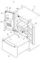
- Figure 2 is a perspective view showing an embodiment of the appearance of the refrigerator door in the open state.
- FIG. 3 is a diagram illustrating an embodiment of a user interface.
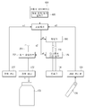
- FIG. 4 is a view for explaining the production and supply process of the carbonated water of the refrigerator, and the production or supply process of ice or purified water.
- 5A illustrates one embodiment of a dispenser.
- 5B is a view illustrating a carbon dioxide supply module and a carbonated water preparing module installed in the dispenser.
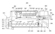
- FIG. 6 is a view illustrating a carbon dioxide supply module and a carbonated water preparing module.
- FIG. 7 is a view illustrating the carbonated water preparing module and the intake container.
- FIG. 8 is an exploded perspective view of the carbonated water preparing module and the intake container.
- 9 to 12 are views for explaining the nozzle module.
- 14 to 16 are views for explaining an example in which the intake container is mounted to the carbonated water production module.
- 17 to 19 are views for explaining a process of detecting the mounting of the water intake container.
- 20 is a side cross-sectional view of one embodiment of a dispenser assembly.
- 21 is a front view of one embodiment of a dispenser assembly.
- 22 is a cross-sectional view of an embodiment of an ice maker.
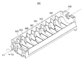
- FIG. 23 is a perspective view of one embodiment of an ice maker.
- 24 is a diagram for explaining an example in which purified water is supplied to an ice making tray.
- 25 is a view showing the internal structure of an embodiment of an ice maker.
- 26 is a control flowchart of an embodiment of a control flow of the refrigerator.
- 27 is a view briefly illustrating a process of coupling the water intake container to the carbonated water preparing module.
- FIG. 28 is a diagram illustrating a change in time of an electrical signal output from a mounting sensor and a lever sensor when a mounting signal is generated.
- FIG. 29 is a view illustrating a change of an electrical signal output from a mounting sensor and a lever sensor according to time when the release signal is generated.
- 30 is a view for explaining the operation of the dispenser lever when the intake container is not coupled.
- 31 is a control flowchart of another embodiment of the control flow of the refrigerator.
- FIG. 32 is a diagram illustrating an example in which ice making is stopped according to an operation of the ice making operation button.
- 33 is a diagram illustrating an example in which the dispenser lever is operated.
- the user interface 34 illustrates an example in which the user interface provides the user with information about the start of the ice making operation at the start of the ice making operation.
- 35 is a diagram illustrating an example in which the dispenser lever is returned to its original state.
- FIG. 36 illustrates an example in which the user interface provides the user with information about stopping the ice making when the ice making operation is stopped.
- FIG. 37 is a flowchart illustrating a first embodiment of a control method of a refrigerator.
- 38 is a flowchart of a second embodiment of a control method of a refrigerator.
- 39 is a flowchart of a third embodiment of a control method of a refrigerator.
- FIG. 40 is a flowchart of a fourth embodiment of a control method of a refrigerator.
- 41 is a flowchart of a fifth embodiment of a control method of a refrigerator.
- Figure 2 is a perspective view showing an embodiment of the appearance when the door of the refrigerator is open.
- the refrigerator 1 may include a main body 10 forming an exterior of the refrigerator 1, and one or more storage chambers 20 formed in an inner space of the main body 10. 30). Doors 21, 22, and 31 may be provided at one side of the main body 10 to open and close the storage compartments 20 and 30.
- the main body 10 is disposed between an inner wound forming the storage compartments 20 and 30, an outer wound coupled to the outside of the inner wound to form the exterior of the refrigerator, and an inner wound and the outer wound to insulate the storage compartments 20 and 30 from the outside. It may include insulation.
- the storage compartments 20 and 30 may be partitioned into a plurality of storage compartments 20 and 30 by the intermediate partition 11, and in this case, the intermediate partition 11 may be divided into the storage compartments 20 and 30 up and down. It can also be partitioned from side to side.
- the refrigerator 1 may include a plurality of intermediate partitions 11, and thus, the storage rooms 20 and 30 may be divided into three or more and provided in the refrigerator 1.
- the plurality of storage chambers 20 and 30 may include a refrigerating chamber for refrigerating the stored object, and a freezing chamber for freezing and storing the stored object.
- the storage chambers 20 and 30 may be kept at a predetermined temperature, for example, at a temperature of 3 degrees of image, to store the stored object.
- the freezer may be kept at a predetermined temperature, approximately minus 18.5 degrees, to freeze the stored object. I can keep it.
- the temperature inside the storage compartments 20 and 30 may be variously set according to a user's selection. In this case, the user may set a temperature inside the storage rooms 20 and 30 using the user interface 400.
- the object of storage means various objects that can be refrigerated at low temperature, and may include, for example, food or medicine.
- the at least one storage compartment 20 may be provided with a shelf 23 on which an object to be stored may be placed, and at least one storage box 27 for hermetically storing the object to be stored may be disposed.
- the at least one storage box 27 may be installed in the storage chamber 20 to be discharged from the inside of the storage chamber 20 to the outside by the user.
- An ice maker 800 may be installed in the storage compartments 20 and 30.
- the ice maker 800 is an apparatus which freezes the purified water supplied and produces ice.
- the ice maker 800 may be installed in the refrigerating compartment or may be installed in the freezing compartment, depending on the embodiment. After the ice generated by the ice maker 800 is discharged to the outside of the ice maker 800, the water intake space (116) is provided inside the door 21 and connected to the dispenser assembly 100 through the ice connection passage 117 and the discharge hole 116. 132). Details of the ice maker 800 will be described later.
- various devices for the convenience of the user may be installed in the storage compartment 20.
- the storage compartments 20 and 30 may each have a front surface open to withdraw food, and the open front surface may be opened and closed by a pair of doors 21 and 22 coupled by the body 10 and a hinge. have. According to an embodiment, the opened front surface may be opened and closed by a sliding door 31 which is slidably movable with respect to the main body 10.
- the storage doors 21 and 22 may include a front surface exposed to the outside when the storage chambers 20 and 30 are closed and a rear surface facing the storage chambers 20 and 30.
- a portion of the dispenser assembly 100 may be exposed on the front surface of at least one of the storage doors 21 and 22, and also receives a control command related to the operation of the refrigerator 1 from the user, or operates the refrigerator 1.
- a user interface 400 for displaying information may be provided.
- FIG. 3 is a diagram illustrating an embodiment of a user interface.
- the user interface 400 may include a display unit 410 for providing various types of information to the user, and an input unit 420 for receiving various commands from the user.
- the display unit 410 is provided to display and provide at least one of a current operation state of the refrigerator 1, a setting related to the operation of the refrigerator 1, and various kinds of information necessary for convenience of the user.
- the display unit 410 may display information on an operation state of the current refrigerator.
- the display unit 410 may display the internal temperatures 411 and 412 of the respective storage compartments 20 and 30.
- one of the displayed internal temperatures 411 and 412 411 may be a temperature of the freezer compartment, and the other 412 may be a temperature of the refrigerating compartment.
- the display unit 410 may display information on a current state related to the operation of the refrigerator 1, such as a residual amount of carbon dioxide in the carbon dioxide cylinder 222, to the user. In addition to the produced carbonated water concentration, it is possible to display a variety of information necessary for the user's convenience.
- the display unit 410 may display information 413 on what operation the refrigerator is currently performing. For example, the display unit 410 may display information 413a on whether the carbonated water production operation is performed, or text 413b on whether the ice maker 800 is performing the ice making operation. It may also be displayed using at least one of symbols, numbers, and various shapes.
- the display unit 410 is the current setting for the various operations of the refrigerator 1, for example, the temperature setting value for each of the storage compartments (20, 30), the setting value for the amount of carbon dioxide administered in the production of carbonated water, etc.
- the dispenser assembly 100 may display information about whether the dispenser assembly 100 is currently set to provide an integer or ice.
- the display unit 410 may be implemented using, for example, at least one lighting device.
- Lighting device is incandescent bulb, halogen lamp, fluorescent lamp, sodium lamp, mercury lamp, fluorescent mercury lamp, xenon lamp, arc lamp, neon tube lamp, EL lamp (electroluminescent lamp), light emitting diode (LED, Light Emitting Diode) ) It can be implemented by adopting various kinds of lighting devices such as lamps, Cold Cathode Fluorescent Lamps (CCFLs), or External Electrode Fluorescent Lamps (EEFLs). Can be displayed using a blinking pattern of light or a color of light.
- CCFLs Cold Cathode Fluorescent Lamps
- EEFLs External Electrode Fluorescent Lamps
- the display unit 410 may be implemented by using, for example, a lighting device and a substrate provided with a light emitting port.
- the light emitting port is implemented in a predetermined shape, it is provided so that the light irradiated by the lighting device is emitted to the outside.
- the display unit 410 may provide a variety of information to the user according to the shape of the light emitting port.
- the display unit 410 may be implemented using, for example, various types of display panels.
- the display panel may be implemented by adopting a liquid crystal display (LCD) panel, a light emitting diode (LED) display panel, or the like.
- the display unit 410 may be implemented as a touch screen. In this case, the display unit 410 may also perform a function of the input unit 420.
- the input unit 420 may receive various user commands related to the operation of the refrigerator 1.
- the input unit 420 may output a predetermined electrical signal according to a user's operation and transmit the output signal to a control device that controls the refrigerator through a circuit or an electric wire, for example, a processor (300 of FIG. 26 or 31). have.
- the input unit 420 may receive, from a user, various commands necessary for controlling the refrigerator 1 such as a target temperature of the storage compartment 20, a target temperature of the freezer compartment 30, a carbonated water production command, and a carbonated water target concentration.
- the input unit 420 may include a freezer compartment temperature control command input unit 421, a door open notification signal control command input unit 422, a carbonated water production command input unit 423, and a cold room temperature control command.
- the input unit 424 may include at least one of an illumination driving command input unit 425, an ice maker operation / stop input unit 426, an integer discharge command input unit 441, and an ice discharge command input unit 442.
- the user manipulates the freezer compartment temperature control command input unit 421 and the refrigerator compartment temperature control command input unit 424 to adjust the temperature of the freezer compartment or the refrigerating compartment 20, 30, or the carbonated water production command input unit 423 to issue a carbonated water production command. You can enter
- the user may operate the ice maker operation / stop input unit 426 to control the ice maker 800 to perform the ice making operation or to stop the ice making operation.
- the ice maker operation / stop input unit 426 may be implemented by one operation means, for example, a physical button, or may be implemented by a plurality of operation means.
- the user may input the operation start command of the ice maker 800 or all of the operation stop commands of the ice maker 800 by sequentially operating the operation means. can do.
- the ice maker operation / stop input unit 426 is implemented with a plurality of operation means, the user operates each operation means to input an operation start command of the ice maker 800 or an operation stop command of the ice maker 800. can do.
- the user operates at least one of the purified water discharge command input unit 441 and the ice discharge command input unit 442 to provide a command to the refrigerator 1 to determine whether the purified water or ice is discharged according to the operation of the dispenser lever 136.
- the refrigerator 1 discharges the purified water through the discharge port 116 after the dispenser lever 136 is operated after the constant discharge command input unit 441 is operated, and after the ice discharge command input unit 442 is operated.
- the dispenser lever 136 is operated, ice may be discharged through the discharge port 116.
- Each of the input units 420 to 428 described above may include various physical buttons, keyboard device knobs, levers, track balls, track pads, motion detection sensors, touch detection sensors, touch buttons, touch pads, light detection sensors, and touch screens. It may be implemented using various input means capable of outputting an electrical signal according to external manipulation.
- Each of the ice maker operation / stop input unit 426, the water discharge command input unit 441, and the ice discharge command input unit 442 may be implemented using the same input means, or may be implemented using different input means.
- the ice maker operation / stop input unit 426 may be implemented as a touch button, and the integer discharge command input unit 441 and the ice discharge command input unit 442 may be implemented as physical buttons.
- the position, shape, or type of input means for implementing the input unit 426, the integer discharge command input unit 441, and the ice discharge command input unit 442 may be implemented in various ways according to a designer's arbitrary choice. have.
- the user interface 400 may further include a sound output device such as a speaker device in order to provide the user with various information related to the refrigerator 1 or various information necessary for user convenience.
- a sound output device such as a speaker device
- the user interface 400 may not be directly installed in the refrigerator 1.
- the user interface 400 may be implemented by a terminal device spaced apart from the refrigerator 1.
- the terminal device may be implemented using, for example, a smartphone, a cellular phone, a tablet PC, a laptop computer, a desktop computer, a portable game machine, a navigation device, or the like.
- the dispenser assembly 100 may provide purified water, carbonated water, or ice through a portion exposed to the front surface, so that the user may obtain purified water, carbonated water, or ice from the outside without opening the storage compartment door 21.
- Door guards 24 for accommodating food may be provided on the rear surfaces of the storage compartment doors 21 and 22.
- the storage compartment doors 21 and 22 close the storage compartments 20 and 30 on the rear edges of the storage compartment doors 21 and 22, the storage compartment doors 21 and 22 are sealed between the main compartment 10 and the storage compartment doors 21 and 22.
- a gasket 28 may be further provided to prevent the outflow of cold air of the 20.
- At least one of the storage doors 21 and 22 is sealed between the storage door 21 and the storage door 22 when the storage doors 21 and 22 are closed.
- Rotating bar 26 may be provided to prevent the outflow of cold air.
- the door 21 of the refrigerator 1 may be equipped with a second dispenser assembly 200 for preparing carbonated water and providing the same to a user.
- a second dispenser assembly 200 for preparing carbonated water and providing the same to a user.
- FIG. 4 is a view for explaining a dispenser assembly for producing and supplying carbonated water of a refrigerator and for preparing or supplying ice or purified water.
- the dispenser assembly 100 may include a first dispenser assembly 110 and a second dispenser assembly 200, and may further supply purified water to the first dispenser assembly 110 and the second dispenser assembly 200. It may further include (211).
- the purified water supply unit 211 blocks the water supply source 212, the purified water flow passage 215 and the purified water flow passage 215, which are flow passages through which the water supplied to the first dispenser assembly 110 or the carbonated water production module 250 passes. It may include an open water valve (216).
- the purified water supply unit 211 further includes an ice making channel 213 for connecting the water supply source 212 and the ice maker 800, and an ice making valve 214 for blocking or opening the ice making channel 213. It may include.
- the purified water supply unit 211 may further include a flow sensor 218 for detecting the amount of purified water supplied to the first dispenser assembly 110 or the carbonated water production module 250.
- the water supply source 212 is a device for supplying purified water to the purified water supply unit 211, may be a separately provided water tank, or may be a water pipe connected to a general home or a factory.
- the water supply source 212 is connected to at least one of the ice making flow passage 213 and the purified water flow passage 215, and the water supplied from the water supply source 212 receives the first water through the ice making flow passage 213 or the water purification flow passage 215.
- the dispenser assembly 110, the carbonated water preparing module 250, or the ice maker 800 may be delivered.
- the purified water valve 216 is provided to open and close the purified water flow path 215 through which purified water is supplied from the water supply source 212 to the first dispenser assembly 110 or the carbonated water preparing module 250.
- the ice making valve 214 is provided to open and close the ice making flow path 213 through which the purified water is supplied from the water supply source 212 to the ice making machine 800.
- Purified water may be supplied to the ice maker 800 according to the operation of the ice maker 214, and the ice maker 800 may freeze the purified purified water to generate ice.
- the ice making valve 214 may be opened or closed according to the operation of the processor 300 separately provided, and the processor 300 may open or make the ice making valve 214 according to the operation of the ice maker operation / stop input unit 426 of the user. Can be closed.
- the ice maker valve 214 may be opened under the control of the processor 300 to supply purified water to the ice maker 800 when the dispenser lever 136 is operated even when the ice maker 800 is stopped. It may be.
- the ice making valve 214 and the purified water valve 216 are delivered to at least one of the ice maker 800, the first dispenser assembly 110, and the carbonated water preparing module 250 while blocking the strong water pressure coming from the water supply source 212. You can adjust the amount of integers.
- the ice making valve 214 and the water purification valve 216 may be, for example, a solenoid valve. However, the type and shape of the ice making valve 214 and the water purification valve 216 are not limited thereto.
- the water supply source 212, at least one of the ice making valve 214 and the water purification valve 216 may be directly connected to each other through the flow paths 213 and 215, as shown in FIG. 4.
- a flow path switching valve (not shown) may be further provided between the water supply source 212 and at least one of the ice making valve 214 and the water purification valve 216.
- the flow path switching valve may be a valve designed to supply purified water supplied from the water supply source 212 to at least one of the first dispenser assembly 110, the carbonated water preparing module 250, or the ice maker 800.
- the flow path switching valve is the purified water flow path 215 connected to the first dispenser assembly 110 or the carbonated water production module 250.
- the purified water may be supplied only to the first dispenser assembly 110 or the carbonated water preparing module 250.
- the flow path switching valve closes the flow path 215 connected to the first dispenser assembly 110 or the carbonated water production module 250, and the flow path connected to the ice maker 800 ( By opening 215, the purified water may be supplied to the ice maker 800. Accordingly, the ice maker 800 may perform an ice making operation.
- the flow path switching valve may include an inlet connected to the water supply source 212, a first outlet connected to the ice maker 800, and a first dispenser assembly 110 or a carbonated water production module 250. It can be implemented using a three-way valve including two outlets.
- the flow sensor 218 may calculate the amount of purified water supplied from the water supply source 212 to the first dispenser assembly 110 or the carbonated water preparing module 250.
- 4 illustrates an example in which the flow sensor 218 is disposed between the first dispenser assembly 110 or the carbonated water preparing module 250 and the purified water valve 216, but the flow sensor 218 is not limited thereto.
- the flow sensor 218 may be disposed upstream of the purified water valve 216 and the ice making valve 214 to calculate the amount of purified water supplied to the purified water supply unit 211.
- the flow rate sensor 218 and the purified water supply part 211 shown in FIG. 4 only show an example of the purified water supply means employ
- the first dispenser assembly 110 may provide purified water or ice to the user.
- the first dispenser assembly 110 may include a first dispenser supply passage 112 connected to the purified water supply unit 211 and a first dispenser supply valve configured to open and close the first dispenser supply passage 112. 114a).
- the first dispenser assembly 110 may further include a second dispenser supply passage 118 connected to the ice maker 800.
- the first dispenser assembly 110 may include a second dispenser supply valve 114b for opening and closing the second dispenser supply passage 118.
- the first dispenser supply passage 112 may guide the purified water toward the water intake space 132.
- the first dispenser supply valve 114a may be opened and closed to adjust an amount of purified water supplied to the water intake space 132.
- the first dispenser supply valve 114a may be opened or closed according to a control signal transmitted from the outside. Specifically, when the user operates the dispenser lever 136, the first dispenser supply valve 114a may be opened or closed by an electrical signal output from the dispenser lever 136. Or may be opened or closed by an electrical control signal generated by the processor 300 based on the electrical signal output from the dispenser lever 136. Accordingly, when the user presses and operates the dispenser lever 136, purified water may be provided to the user.
- the first dispenser supply valve 114a may be implemented using, for example, a solenoid valve.
- the first dispenser supply valve 114a may be used. The opening and closing may adjust the amount of ice supplied to the intake space 132. In this case, the second dispenser supply valve 114b may be omitted.
- the second dispenser supply passage 118 may guide the ice generated by the ice maker 800 toward the intake space 132.
- the second dispenser supply valve 114b may adjust the amount of ice supplied to the water intake space 132.
- the second dispenser supply valve 114b may also be opened and closed according to a control signal transmitted from the outside.
- the second dispenser supply valve 114b is opened or closed by an electrical signal output from the dispenser lever 136, or an electrical signal output from the dispenser lever 136. It may be opened and closed by the control signal generated by the processor 300 based on the. Accordingly, when the user presses and operates the dispenser lever 136, ice may be provided to the user.
- the second dispenser supply valve 114b may be implemented using, for example, a solenoid valve.
- the second dispenser supply valve 114b may be omitted in some embodiments.
- the second dispenser assembly 200 may prepare carbonated water and provide the same to a user.
- the second dispenser assembly 200 may include a carbon dioxide supply module 220 and a carbonated water preparing module 250, as shown in FIG. 4.
- the carbon dioxide supply module 220 includes a carbon dioxide cylinder 222 for storing carbon dioxide and a carbon dioxide supply valve 230 for controlling the amount of carbon dioxide supplied from the carbon dioxide cylinder 222 to the carbonated water production module 250.
- the carbon dioxide cylinder 222 may store high pressure carbon dioxide, and the atmospheric pressure of carbon dioxide may be about 45 to 60 bar.
- the carbon dioxide stored in the carbon dioxide cylinder 222 may be discharged to the intake container 170 through a carbon dioxide supply passage 224 connecting between the carbon dioxide cylinder 222 and the carbonated water production module 250.
- the carbon dioxide supply passage 224 may guide carbon dioxide stored in the carbon dioxide cylinder 222 to the carbonated water preparing module 250.
- a carbon dioxide supply valve 230 may be provided on the carbon dioxide supply passage 224 to open and close the carbon dioxide supply passage 224. When the carbon dioxide supply valve 230 is opened, the carbon dioxide stored in the carbon dioxide cylinder 222 is discharged to the water intake container 170 through the carbon dioxide supply passage 224.
- the carbon dioxide supply valve 230 may include a solenoid valve for opening and closing the carbon dioxide supply flow path by an electrical signal. Details of the carbon dioxide supply valve 230 will be described later.
- the carbon dioxide supply module 220 may include a carbon dioxide pressure sensor 233.
- the carbon dioxide pressure sensor 233 may detect a discharge pressure of carbon dioxide discharged from the carbon dioxide cylinder 222.
- the carbon dioxide pressure sensor 233 may be implemented by using a pressure switch that outputs a low pressure detection signal when the pressure of the carbon dioxide discharged is lowered below the threshold.
- the carbonated water preparing module 250 is made to be separated from the intake container 170, and when the intake container 170 is coupled, the carbonated water is produced in the intake container 170 by releasing carbon dioxide into the intake container 170. Make it possible.
- the carbonated water preparing module 250 may include a purified water inflow passage 251 connected to the purified water supply unit 211 and a purified water inflow valve 252 for opening and closing the purified water inflow passage 251. Through the opening and closing of the purified water inlet valve 252, it is possible to adjust the amount of purified water introduced into the intake container 170.
- the carbonated water production module 250 may include a carbon dioxide inflow passage 254 connected to the carbon dioxide supply module 220 and a nozzle module 280 provided to operate by carbon dioxide introduced into the carbon dioxide inflow passage 254.
- the nozzle module 280 is operated by the carbon dioxide supplied to the carbonated water preparing module 250, and is provided to inject the supplied carbon dioxide into the water intake container 170.
- the nozzle module 280 will be described in detail later.
- the carbonated water preparing module 250 may include a vent valve 258.
- the vent valve 258 is provided to prevent excessively increasing the pressure inside the intake container 170 by the injected carbon dioxide when injecting carbon dioxide into the intake container 170. Specifically, when the carbon dioxide pressure in the intake container 170 exceeds a predetermined pressure, the vent valve 258 is opened, and the carbon dioxide in the intake container 170 is discharged to the outside.
- the second dispenser assembly 200 may include a relief valve 150.
- the relief valve 150 is provided so that the purified water or the carbonated water that is overflowed may be discharged when the purified water that exceeds a predetermined amount is supplied to the purified water or the carbonated water that exceeds the predetermined amount.
- 5A illustrates one embodiment of a dispenser assembly.
- the dispenser assembly 100 may be installed in the door 21.
- the dispenser assembly 100 includes a dispenser housing 130 which is formed to be recessed in the rear direction from the front of the door to form the intake space 132 and the intake space 132 exposed to the outside from the front of the door 21. can do.
- the intake space 132 may accommodate the intake container 170.
- Intake container 170 may be provided to be separated in the carbonated water production module 250 in the intake space (132).
- the mounting body 272 on which the intake container 170 is mounted in the carbonated water preparing module 250 may be provided to be exposed in the intake space 132.
- a dispenser lever 136 operable by a user may be provided to control the discharge of ice generated by the purified water or ice maker 800.
- the second dispenser assembly 110 may discharge purified water or ice into the water intake space 132.
- a water collecting case 134 may be provided at a lower portion of the dispenser housing 130 to collect discharge liquids such as purified water and carbonated water that are discarded in the water intake space 132.
- the inner surface of the dispenser housing 130 may be inclined at a predetermined inclination so that the discharge liquid discharged to the intake space 132 may be easily collected into the collection case 134.
- the dispenser housing 130 may include a cylinder accommodating space 221 into which the carbon dioxide cylinder 222 may be inserted or removed.
- the cylinder receiving space 221 may be provided adjacent to the intake space 132, for example, may be formed on one side of the intake space 132 as shown in FIG. 5A.
- the carbon dioxide cylinder 222 is disposed in the cylinder receiving space 221, and the carbon dioxide cylinder 222 may be mounted to the cylinder connector 231 provided inside the cylinder receiving space 221.
- the carbon dioxide of the carbon dioxide cylinder 22 may be supplied to the carbon dioxide supply passage 224.
- the dispenser housing 130 may include a cylinder door 221a for opening and closing the cylinder accommodation space 221.
- the cylinder door 221a may open and close the cylinder accommodation space 221 by hinge coupling. have.
- the above-described user interface 400 may be installed in a part of the dispenser housing 130.
- the user interface 400 includes a display unit 41 of FIG. 21 or an illumination unit 44 of FIG. 21 that displays operation information of the refrigerator 1 to the user, and the user to the refrigerator 1. It may include an operation unit (45 of FIG. 21) for receiving various control commands.
- the second dispenser assembly 200 may be provided inside the dispenser housing 130 to supply purified water and carbon dioxide to the intake container 170 accommodated in the intake space 132.
- Figure 5b is a view showing a carbon dioxide supply module and carbonated water production module installed in the dispenser
- Figure 6 is a view showing a carbon dioxide supply module and carbonated water production module
- 7 is a view showing the carbonated water production module and the intake vessel
- Figure 8 is an exploded perspective view of the carbonated water production module and the intake vessel.
- the second dispenser assembly 200 may include a module cover 202 to surround the outside of the carbon dioxide supply module 220 or the carbonated water preparing module 250.
- the module cover 202 prevents damage due to external impact by preventing the connection between the purified water and carbon dioxide flowing in the second dispenser assembly 200 and the connection portion of each flow path to the outside.
- the module cover 202 may be provided to cover at least a portion of the carbon dioxide supply module 220 and the carbonated water production module 250, so that the module cover 202 is a noise generated during the flow of purified water and carbon dioxide You can also block it.
- Carbonated water production module 250 the intake container 170 is provided to be detachable, it is possible to inject purified water and carbon dioxide into the intake container 170 is mounted.
- the carbonated water preparing module 250 may include a manufacturing module body 260.
- the manufacturing module body 260 may include a mounting body 272 on which the water intake container 170 is mounted.
- the mounting body 272 is provided to be exposed to the water intake space 132, and the water intake container 170 is provided to be mountable. That is, the water intake container 170 is provided to be mounted to the mounting body 272, and is configured to be detachable from the mounting body 272.
- One side of the mounting body 272 is provided with a mounting sensor 277 for detecting the mounting of the water intake container 170.
- the mounting body 272 and the mounting sensor 277 will be described later in detail.
- the carbonated water preparing module 250 may include a purified water inflow pipe 253 forming a purified water inflow flow path 251 and a carbon dioxide inflow pipe 255 forming a carbon dioxide inflow flow path.
- the purified water flowing through the purified water inlet 215 may be introduced into the purified water inlet pipe 253, and the carbon dioxide flowing through the carbon dioxide supplying channel may be introduced into the carbon dioxide inlet pipe 255.
- the purified water and carbon dioxide introduced through the purified water inlet pipe 253 and the carbon dioxide inlet pipe 255 may be injected into the intake container 170 to prepare carbonated water.
- the purified water inlet pipe 253 and the carbon dioxide inlet pipe 255 may be coupled to the manufacturing module body 260.
- the mounting body 272 is formed on one side of the manufacturing module body 260, the purified water inlet pipe 253 and the carbon dioxide inlet pipe 255 may be coupled to the other side of the manufacturing module body 260. More specifically, the mounting body 272 may be formed in the second module body 271, and the purified water inlet pipe 253 and the carbon dioxide inlet pipe 255 may be coupled to the first module body 261.
- the second dispenser assembly 200 may include one or more relief valves 150 and a drainage module 160.
- the relief valve 150 may supply purified water that exceeds a certain amount to the intake container 170, or when excess carbonated water is produced in the intake container 170, The carbonated water can be discharged to the outside.
- the relief valve 150 may be provided to be coupled to the production module body 260 of the carbonated water production module 250. More specifically, one end of the relief valve 150 is provided to communicate with the inside of the intake container 170 when the intake container 170 is mounted to the carbonated water production module 250, the other end of the relief valve 150 is a drainage module ( 160). Carbonated water or high pressure carbon dioxide discharged through the relief valve 150 may be introduced into the drainage module 160.
- the drainage module 160 may discharge carbonated water that flows from the intake container 170 by bypassing the intake container 170.
- the drainage module 160 may be provided to surround the discharge part of the relief valve 150.
- the carbonated water preparing module 250 may include a nozzle module 280.
- the nozzle module 280 may inject carbon dioxide into the water intake container 170.
- the nozzle module 280 may be operated by carbon dioxide supplied from the carbon dioxide supply module 220 and introduced into the carbonated water preparing module 250. The configuration and operation of the nozzle module 280 will be described later in detail.
- the manufacturing module body 260 may include a first module body 261 and a second module body 271.
- the purified water inflow pipe 253 and the carbon dioxide inflow pipe 255 may be combined.
- the nozzle moving part 262 is installed in the first module body 261 to move the nozzle module 280.
- the nozzle moving unit 262 is installed inside the carbon dioxide inlet pipe 255 to allow the nozzle module 280 to move by the carbon dioxide flowing into the carbon dioxide inlet pipe 255.
- An upper portion of the second module body 271 may be coupled to a lower portion of the first module body 261, and a mounting body 272 to which the intake container 170 may be mounted may be formed at the lower portion of the second module body 271.
- the intake container 170 may be coupled to or separated from the second module body 271.
- a stopper 271b for limiting the movement of the nozzle module 280 may be installed in the second module body 271.
- the stopper 271b may be provided on an upper surface of the second module body 271 to limit the movement of the nozzle module 280 that moves the nozzle mover 262.
- carbon dioxide when carbon dioxide is supplied to the carbonated water preparing module 250, it is provided to limit the movement of the nozzle tube 282 to the supplyable position P2.
- the first module body 261 and the second module body 271 may be connected to each other using various means.
- the first module body 261 and the second module body 271 may be coupled through the coupling bolt 263a and the coupling nut 263b.
- the method of squeezing them is not limited thereto, and may be swept together using, for example, an epoxy adhesive.
- 9 to 12 are views for explaining the nozzle module.
- the nozzle module 280 may move by the carbon dioxide introduced into the carbonated water preparing module 250 to directly inject carbon dioxide from the inside of the intake container 170.
- the nozzle module 280 may directly inject carbon dioxide under the purified water stored in the intake container 170, and inject the carbon dioxide directly under the purified water according to the embodiment. Therefore, the injected carbon dioxide is in direct contact with the purified water and can be more easily dissolved in the purified water.
- the nozzle module 280 may include a nozzle tube 282 and a valve unit 290.
- the nozzle pipe 282 is provided to be movable in the nozzle moving part 262.
- a carbon dioxide injection nozzle 286 is formed at one end of the nozzle tube 282, and carbon dioxide flowing into the other end may be injected through the carbon dioxide injection nozzle 286.
- the nozzle tube 282 may include a nozzle tube passage 282a through which carbon dioxide flows.
- the valve unit 290 is formed at the other end of the nozzle tube 282.
- the valve unit 290 may include an inlet hole 291 and a valve unit 292. Carbon dioxide may be introduced into the nozzle tube 282 from the inside of the carbonated water preparing module 250 into the inlet hole 291.
- the valve unit 292 may control the inflow of carbon dioxide by opening and closing the inlet hole 291.
- the valve unit 292 may induce the inflow of carbon dioxide by opening the inlet hole 291 when the pressure inside the carbon dioxide inlet pipe 255 exceeds a predetermined pressure. Since the valve unit 290 is provided at the other end of the nozzle tube 282, the other end of the nozzle tube 282 is sealed by the valve unit 290 when no carbon dioxide pressure is applied to a predetermined level or more.
- the valve unit 290 may include a valve housing 293.
- An inlet hole 291 may be formed in the valve housing 293, and a valve unit 292 may be located therein.
- the valve housing 293 is coupled to the nozzle tube 282 so that the valve portion 292 inside the valve housing 293 may move inside the valve housing 293 without being separated.
- the nozzle module 280 can move the standby position P1, the supply possible position P2, and the supply position P3.
- the standby position P1 indicates the position of the nozzle module 280 when the pressure inside the carbon dioxide inlet pipe 255 is less than the first pressure even when carbon dioxide is not supplied from the carbon dioxide supply module 220 or is supplied. it means.
- the carbon dioxide injection nozzle 286 may be disposed on the surface of the purified water of the intake container 170.
- Supply possible position (P2) when the carbon dioxide is supplied from the carbon dioxide supply module 220 to the carbon dioxide inlet pipe 255 of the carbonated water production module 250, the internal pressure of the carbon dioxide inlet pipe 255 is the first pressure, It means the position where the nozzle module 280 moves. In this case, the carbon dioxide injection nozzle 286 may move to be located below the surface of the reservoir purified water intake container 170.
- the supply position P3 is a second pressure in which carbon dioxide is supplied from the carbon dioxide supply module 220 to the carbon dioxide inlet pipe 255 of the carbonated water production module 250 so that the internal pressure of the carbon dioxide inlet pipe 255 is greater than the first pressure.
- When increased to, means the position where the nozzle module 280 moves.
- the carbon dioxide injection nozzle 286 may inject carbon dioxide.
- the nozzle module 280 may include a nozzle elastic member 284.
- the nozzle elastic member 284 may elastically support the nozzle tube 282 and may be provided to surround the nozzle tube 282. In this case, one end of the nozzle elastic member 284 may be disposed to be supported by the valve unit 290 and the other end of the nozzle elastic member 284 by the stopper 271b of the second module body 271.
- the nozzle elastic member 284 may elastically support the nozzle tube 282 so that the nozzle module 280 maintains the standby position P1 until the carbon dioxide pressure inside the carbon dioxide inlet pipe 255 becomes the first pressure. .
- the valve unit 290 may include a valve elastic member 294.
- the valve elastic member 294 elastically supports the valve portion 292.
- one end of the valve elastic member 294 may be provided by the valve unit 292, and the other end thereof by the nozzle tube 282.
- the valve elastic member 294 is a valve portion 292 so that the nozzle module 280 can be moved from the supply possible position P2 to the supply position P3 when the carbon dioxide pressure inside the carbon dioxide inlet pipe 255 is the second pressure. ) Can be elastically supported.
- the valve elastic member 294 may elastically support the valve unit 292 so that the nozzle module 280 maintains the supplyable position P2 when the internal pressure of the carbon dioxide inlet pipe 255 is less than the second pressure. Since the second pressure is greater than the first pressure, the elastic force of the valve elastic member 294 may be greater than the elastic force of the nozzle elastic member 284.
- the valve elastic member 294 When the carbon dioxide pressure inside the carbon dioxide inlet pipe 255 becomes the second pressure, the valve elastic member 294 is compressed, and the valve portion 292 opens the inlet hole 291.
- the carbon dioxide of the carbon dioxide inlet pipe 255 passes through the open inlet hole 291, flows along the nozzle tube flow path 282a, and is located in the carbon dioxide injection nozzle 286 located below the stored water purification surface inside the intake container 170. Can be discharged through.
- the injection nozzle 286 can directly inject carbon dioxide under the surface of purified water stored in the intake container 170, it is possible to improve the solubility of carbon dioxide, thereby improving the carbonated water production efficiency. Can be.
- the first pressure and the second pressure described above may be set in various ways, but the second pressure may be set to be greater than the first pressure.
- the first pressure may be set to 0.5 bar
- the second pressure is set to 1.5 bar.
- the first pressure and the second pressure are not limited thereto, and may be variously set according to the carbonated water production environment or a designer's arbitrary choice.
- the water intake container 170 may include a container body 172 capable of storing liquid therein and an opening 173 through which liquid may be introduced or discharged from the container body 172. have.
- the container body 272 may have a cylindrical shape as shown in FIG. 15.
- the shape of the container body 272 is not limited thereto, and may have a shape such as a hexahedron or the like, or may have various shapes according to a user's preference.
- the opening 173 may be provided at one side of the container body 172.
- the protrusion 173a may be formed at one end of the container body 172, and the opening 173 may be formed at one end of the protrusion 173a.
- the opening 173 of the intake container 170 may have a substantially circular shape. According to an embodiment, the shape of the opening 173 may be provided to correspond to the shape of the container body 172.
- the intake container 170 may include one or more seating protrusions 174 protruding from the container body 172.
- the mounting protrusion 174 may be provided adjacent to the opening 173, and may be formed in the protrusion 173a according to the embodiment.
- the seating protrusion 174 may be formed to radially protrude around the opening 173. When a plurality of seating protrusions 174 are formed, the seating protrusions 174 may be spaced apart from each other at regular intervals. 172 may be formed.
- an opening 173 is inserted into the mounting body 272, and the seating protrusion 174 is seated on the seating portion 273 of the mounting body 272. Can be.
- the intake container 170 may be provided to be easily carried separately after being separated from the mounting body 272. To this end, the intake container 170 may be further formed with a handle so that the user can easily grip.
- a cover 175 for opening and closing the opening 173 may be mounted at one end of the intake container 170.
- 14 to 16 are views for explaining an example in which the intake container is mounted to the carbonated water production module.
- the manufacturing module body 260 detects a mounting body 272 on which the intake container 170 is mounted, and whether the intake container 170 and the mounting body 272 are coupled to each other. It may further include a mounting sensor (277).
- the mounting body 272 may include a seating portion 273 on which the seating protrusion 174 of the intake container 170 is seated, and a guide rail 274 for guiding the seating protrusion 174 to the seating portion 273. Can be.
- the seating portion 273 has a shape corresponding to the shape of the seating protrusion 174, thereby allowing the seating protrusion 174 to be stably seated on the seating portion 273.
- the guide rail 274 may extend from the seating portion 273, and may have a predetermined shape such that the seating protrusion 174 may be easily moved to the seating portion 273. If the mounting body 272 has a cylindrical shape, the guide rail 274 may be formed along the inner circumferential surface of the mounting body 272 corresponding to the mounting protrusion 174.
- the mounting protrusion 174 may move along the guide rail 274 in a separation direction or a mounting direction.
- the mounting direction means a direction in which the seating protrusion 174 moves along the guide rail 274 toward the seating portion 273, and the separation direction is the seating protrusion 174 along the guide rail 274. 273).
- the separation direction or mounting direction can be arbitrarily determined by the designer's choice.
- the guide rails 274 may also be formed in the mounting body 272 so that the plurality of guide rails 274 may be spaced apart from each other.
- the mounting body 272 may include an insertion groove 275.
- the insertion groove 275 allows the seating protrusion 174 to be positioned on the guide rail 274 when the water intake container 170 is inserted into the mounting body 272.
- the insertion groove 275 may extend from the guide rail 274 and may be formed in the mounting body 272 along the direction in which the water intake container 170 is inserted into the mounting body 272.
- the mounting body 272 may include a departure prevention protrusion 276.
- the anti-separation protrusion 276 may be formed on the guide rail 274 adjacent to the seating portion 273 to prevent the seating protrusion 174 located at the seating portion 273 from being separated from the seating portion 273. .
- the mounting sensor 277 may detect that the intake container 170 is mounted to the mounting body 272. According to one embodiment, the mounting sensor 277 detects that the seating protrusion 174 moves along the guide rail 274 of the mounting body 272 to the seating portion 273 or prevents the seating protrusion 174 from being separated. Sensing that the protrusion 276 passes through, or detecting the seating protrusion 174 seated on the seating portion 273, or detecting that the seating protrusion 174 moves in the insertion groove 275. Of course, in some embodiments, the mounting sensor 277 may detect all of them.
- the mounting sensor 277 may include a sensing lever 278 and a sensor unit 279.
- the sensing lever 278 is provided to be rotatable.
- the sensing lever 278 may rotate around the sensing lever center axis 278aa, and when the seating protrusion 174 presses one side, the sensing lever 278 may be rotatably provided by an applied pressure.
- the sensing lever 278 is rotatable between the unmounted position 278b and the mounted position 278a.
- the non-mounting position 278b means a corresponding position when the seating protrusion 174 is positioned on the guide rail 274, and the mounting position 278a indicates that the seating protrusion 174 moves the guide rail 274.
- the seating portion 273 means a corresponding position.
- the mounting sensor 277 may further include a return elastic member 277b.
- the return elastic member 277b may allow the sensing lever 278 to return from the mounting position 278a to the unmounted position 278b when the water intake container 170 is separated from the mounting body 272.
- the sensor unit 279 may detect the rotation of the sensing lever 278.
- the sensor unit 279 is provided to correspond to the other side of the sensing lever 278, and is provided to detect the rotation of the sensing lever 278.
- the magnetic side 278bb may be formed on the other side of the sensing lever 278, and the sensor unit 279 may include a reed switch provided to sense the magnetic of the sensing lever 278.
- the sensor unit 279 may include, for example, a micro switch that is pressed by the other side of the sensing lever 278 to be turned on / off.
- the mounting sensor 277 may include a sensor housing 277a.
- the sensor housing 277a may prevent the sensing lever 278 and the sensor unit 279 from being exposed from the outside.
- the sensor housing 277a may prevent the sensing lever 278 and the sensor unit 279 from malfunctioning by the purified water.
- the opening 173 of the intake container 170 may be closed by the carbonated water preparing module 250.
- the opening 173 of the intake container 170 may be sealed by the manufacturing module body 260, or may be sealed by a separate component.
- the carbonated water preparing module 250 may include a packing part 271a to seal the opening 173 of the intake container 170.
- the packing part 271a may be disposed to correspond to the opening 173 of the water intake container 170 in the mounting body 272. When the intake container 170 is attached to the mounting body 272, the packing part 271a may prevent the opening 173 from being sealed and preventing carbonated water from flowing out through the opening 173.
- 17 to 19 are views for explaining a process of detecting the mounting of the water intake container.
- the seating protrusion 174 of the intake container 170 is inserted into the guide rail 274 along the insertion groove 275. Can be.
- the intake container 170 When the intake container 170 is inserted into the mounting body 272, the intake container 170 may be rotated in the mounting direction. In this case, the mounting protrusion 174 is moved along the guide rail 274 in the mounting direction, and finally positioned on the seating portion 273, the intake container 170 is mounted to the mounting body 272.
- the sensing lever 278 of the mounting sensor 277 When the intake container 170 is rotated in the mounting direction, the sensing lever 278 of the mounting sensor 277 is pressed by the mounting protrusion 174 at the unmounted position 278b, and moves to the mounting position 278a, The sensor unit 279 may detect movement of the sensing lever 278 to detect whether the water intake container 170 is mounted. Accordingly, whether the intake container 170 is mounted as the carbonated water production module 250 may be detected. When the movement of the sensing lever 278 is detected, the sensor unit 279 may output a predetermined electrical signal and transmit the predetermined electrical signal to the processor.
- the processor 300 provided in the refrigerator 1 determines that the water intake container 170 is mounted on the mounting body 272 based on the electrical signal transmitted from the sensor unit 279, and thus, the processor 300 in the water intake container 170. Each part can be controlled so that carbonated water production is performed. Then, purified water is supplied into the intake container 170, and carbon dioxide is injected into the purified water to prepare carbonated water.
- the mounting protrusion 174 is not inserted into the guide rail 274. If the mounting protrusion 174 is not seated on the seating portion 273, the mounting sensor 277 maintains the unmounted position 278b, so that the sensor portion 279 does not detect the intake container 170. . In this case, the processor 300 may determine that the intake container 170 is not mounted to the mounting body 272, and control the carbonated water production in the intake container 170 not to be performed. As a result, when the intake container 170 is incorrectly mounted or not mounted, the carbonated water is not manufactured, thereby improving the stability of carbonated water production and improving the safety of the user.
- the intake container 170 When separating the intake container 170 from the carbonated water production module 250, first, the intake container is rotated in the separation direction opposite to the mounting direction. Then, the mounting protrusion 174 of the intake container 170 moves along the guide rail 274 from the mounting portion 273 and reaches the insertion groove 275. When the seating protrusion 174 is separated from the mounting body 272 through the insertion groove 275, the water intake container 170 may be separated from the carbonated water production module 250.
- the sensing lever 278 of the mounting sensor 277 is moved to the unmounted position 278b while the pressure by the mounting protrusion 174 is released from the mounting position 278a. .
- the sensor unit 279 may detect that the sensing lever 278 has moved to the unmounted position 278b and may output an electrical signal corresponding thereto.
- the processor may determine whether the intake container 170 is separated based on the electrical signal transmitted from the sensor unit 279, and transmit the control signal to each part according to the determination result to stop the production of the carbonated water.
- the processor 300 determines whether the intake container 170 is separated according to the interruption of the electrical signal transmitted from the sensor unit 279, and transmits a control signal to each part according to the determination result to stop the production of carbonated water. It may be.
- the operation of the dispenser lever 136 becomes impossible, and the dispenser lever 136 is only available when the intake container 170 is separated from the carbonated water production module 250. It will be described with respect to an embodiment of the refrigerator (1) that can be obtained by operating the purified water or ice.
- FIG. 20 is a side cross-sectional view of one embodiment of a dispenser assembly
- FIG. 21 is a front view of one embodiment of a dispenser assembly.
- the dispenser assembly 100 may be installed to be exposed to the front of at least one of the doors 21, 22, and 31 of the refrigerator 1, and may provide carbonated water to a user. Alternatively, water or ice may be provided to the user.
- the dispenser assembly 100 may include a dispenser housing 130, and the display housing 130 may be recessed in the rear direction from the front of the door to form a water intake space 132.
- the intake space 132 may be formed to a wide enough size so that the intake container 170 is easily inserted and mounted on the mounting body 272.
- the back surface 130a of the intake space 132 may be formed to be inclined at a predetermined angle, thereby allowing the purified water or ice to move smoothly along the back surface 130a of the intake space 132.
- the collection case 134 may be formed at the lower end of the water intake space 132.
- a mounting body 272 to which the intake container 170 is coupled, and a discharge port 116 through which water or ice are discharged may be formed, and the mounting body 272 and the discharge port 116 may be formed.
- it may be provided at the top of the intake space 132 so that the purified water or ice can naturally move by gravity.
- the mounting body 272 and the discharge port 116 may be installed adjacent to each other.
- the mounting body 272 may be installed in the opening direction of the water intake space 132
- the discharge port 116 may be installed in the direction of the rear surface 130a of the water intake space 132.
- the position of the mounting body 272 and the discharge port 116 is not limited thereto.
- both the mounting body 272 and the discharge port 116 may be installed in parallel with each other near the middle of the water intake space 132.
- the mounting body 272 may be formed in the second module body 271, and the second module body 271 may be coupled to the first module body 261 to form a part of the carbonated water preparing module 250.
- the mounting sensor 277 may be installed at the side of the mounting body 272 to detect whether the water intake container 170 is coupled to the mounting body 272.
- the discharge port 116 is formed at the distal end of the dispenser supply channel 112 extending from the dispenser supply channel 112 and can discharge the purified water flowing through the dispenser supply channel 112.
- the dispenser supply passage end 115 may include a first end 115a and a second end 115b.
- the first end 115a may extend from the dispenser supply passage 112.
- the second distal end 115b may extend from the first distal end 115a.
- the second end portion 115b may be manufactured separately from the first end portion 115a and then connected to the first end portion 115a by being coupled to the first end portion 115a.
- the second end portion 115b may be separated from the carbonated water production module 250 by the partition wall 115d, and the partition wall 115d may be the carbonated water production module by purified water or ice flowing in the second end portion 115b. It is possible to prevent the 250 from being damaged.
- the first distal end 115a and the second distal end 115b may be partitioned by an openable and closeable cover 115c, and may be connected to each other or blocked from each other according to the opening and closing of the cover 115c.
- the cover 115c may be opened or closed by a pressure applied by water or ice that moves from the dispenser supply passage 112 to the first end portion 115a or may be opened or closed according to a control signal applied from the outside.
- the dispenser lever 136 may be formed near the rear surface 130a of the intake space 132.
- the dispenser lever 136 may be installed adjacent to the mounting body 277, and in a direction opposite to the direction in which the mounting body 277 is disposed about a predetermined axis, that is, the rear surface of the cancellation space 132 according to the applied pressure. It can be rotated in the direction of 130a.
- the dispenser lever 136 may rotate to move about a predetermined axis in a direction in which the mounting body 277 is disposed, that is, in a front direction.
- the front direction movement of the dispenser lever 136 may be implemented by an elastic body provided separately.
- the dispenser lever 136 is sensed by the dispenser lever sensor unit 139 while moving along the operation unit 136a exposed to the water intake space 132 and the operation unit 136a when the operation unit 136a is operated. It may include a sensing unit 136b.
- the to-be-operated part 136a may have a form in which the user can easily apply a force, and according to an embodiment, may have a shape corresponding to the outer shape of the container held by the user.
- the to-be-operated part 136a can rotate to move about a predetermined axis within a predetermined range.
- the user can rotate the operation part 136a by applying a predetermined pressure to the operation part 136a.
- the purified water or ice is discharged from the discharge port 116.
- the sensing unit 136b may not be exposed to the canceling space 132, and is connected to the operation unit 136a so as to be rotated by the operation unit 136a in the same range around a predetermined axis. You can move in rotation.
- a dispenser lever sensor 139 for sensing the sensing unit 136b may be formed inside the dispenser assembly 100.
- the dispenser lever sensor unit 139 may include a sensor 139a for sensing the sensing unit 136b and a housing 139b incorporating the sensor 139a and related components.
- the sensor 139a may be implemented as a pressure sensor or a touch sensor.
- the sensor 139a detects a contact of the sensing unit 136b and outputs an electrical signal to the processor 300 according to a detection result. do.
- the sensing unit 136b senses contact and outputs an electrical signal to the processor 300.
- the senor 139a may be a reed switch for sensing a magnetic provided in the sensing unit 136b, or a micro switch pressed / on by the sensing unit 136b, in addition to the decompression sensor or the contact sensor. It may be implemented as.
- the dispenser lever sensor unit 139 detects whether the dispenser lever 136 is operated using the sensed unit 136b has been described, but the dispenser lever sensor unit 139 operates the dispenser lever 136.
- the method of detecting whether the present invention is not limited thereto, and various methods that may be considered by the designer may be used.
- the dispenser housing 130 may be provided with a cylinder accommodating space 132 into which a carbon dioxide cylinder 22 may be inserted into a side of the water intake space 132, and a carbon dioxide supply valve at an upper end of the cylinder accommodating space 132. 230 is provided.
- One side of the cylinder receiving space 132 is provided with a cylinder door 221a for opening and closing the cylinder receiving space 132 while being rotated by a hinge.
- the dispenser housing 130 may further include a user interface 400.
- FIG. 22 is a sectional view of an embodiment of an ice maker
- FIG. 23 is a perspective view of an embodiment of an ice maker
- 24 is a view for explaining an example in which the purified water is supplied to the ice making tray
- Figure 25 is a view showing the internal structure of an embodiment of an ice maker.
- the ice maker 800 includes an ice making tray 840 in which purified water is supplied and ice is generated, an ejector 810 for ejecting ice from the ice making tray 840, and an ejector.
- the driving device 860 for driving the 810 the drain duct 830 for guiding the water flowing out of the ice making tray 840 or the defrost water of the ice making tray 840, and the generated ice making tray 840 Insulate the ice bucket 870 for storing the generated ice, the auger motor assembly 880 for driving the auger 873 for conveying the ice, and the refrigerant pipe 802 disposed in the ice making chamber 60.
- it may include an air duct 890 forming a part of the cold air flow path inside the ice making chamber 60.
- a lower portion of the ice making tray 840 may be provided with a groove in which the ice making chamber refrigerant pipe 802 may be installed along the length direction of the ice making tray 840, so that the ice making chamber refrigerant pipe 802 may be in direct contact.
- the ice making tray 840 itself serves as a heat exchanger and cools the purified water contained in the ice making space 849 to obtain ice 99.
- a plurality of heat exchange ribs may be formed at the lower portion of the ice making tray 840 to increase a contact area with air to improve heat exchange performance.
- the ice making tray 840 may be implemented using a material such as aluminum having high thermal conductivity.
- the ice making tray 840 may include an ice making space 849 through which water may be supplied and ice 99 may be generated.
- the ice making space 849 may have various shapes.
- the bottom surface 841 may be formed in an arc shape having a predetermined radius and may have a substantially semi-circular shape.
- the ice making space 849 may be divided into a plurality of unit ice making spaces 849 by a plurality of partitions 842 protruding upward from the bottom surface 841.
- Each partition 842 has an adjacent unit ice making space 849 such that water introduced through at least one water supply port 846 formed in the ice making tray 840 can be supplied to all the unit ice making spaces 849.
- Grooved communication grooves 844 may be formed to communicate them.
- the ice making tray 840 may be disposed to be inclined in the longitudinal direction so that the portion where the water inlet 846 is formed is positioned slightly higher than other portions, and the purified water is provided at the other end at one end inside the ice making tray 840. Can move in the direction.
- the ice making tray 840 may further include an anti-separation wall 843 for preventing the ice formed in the ice making space 849 from dropping and guiding the ice making tray 840 to the slider 850.
- the ice making tray 840 may further include a plurality of cutting ribs 847 capable of breaking the generated ice 99 into a plurality of unit ices.
- the ice 99 generated in the unit ice making space 849 may be integrally formed by the communicating unit 844, and the cutting rib 847 may crush the ice 99 integrally formed as described above.
- the cutting ribs 847 may be formed to protrude upward from all or part of the partition 842 and to contact the release preventing wall 843.
- the cutting rib 847 may generate unit ice by crushing the ice 99 when the ejector 810 rotates to release the ice 99 from the ice making space 849.
- the cutting rib 847 may have a height up to an upper edge of the cutting rib 847 greater than half of a height up to an upper edge of the partition wall 842.
- the ice making tray 840 may heat the ice making tray 840 so that the ice 99 may be easily separated from the ice making tray 840 during the ice making process.
- a heater 852 may be installed.
- the ice heater 852 may be arranged to be accommodated in the ice heater contact unit 851 formed in a groove shape under the ice tray 840.
- the ejector 810 is provided to separate the ice 99 from the ice making tray 840.
- the ejector 810 may include a rotation shaft 811 rotating in a predetermined direction R1 about a predetermined axis x1 and a plurality of ejector pins 812 protruding from the rotation shaft 811.
- the ejector pin 812 may rotate about the rotating shaft 811 to separate the ice 99 from the ice making space 849.
- the ejector 810 is connected to the driving device 860 that provides the rotational force to the ejector 810, and may rotate in a predetermined direction R1 according to the operation of the driving device 860.
- the ice making tray 840 may further include an opening 845 for discharging excess purified water when the water in excess of a predetermined amount is supplied to the ice making space 849.
- the opening 845 may be formed at, for example, an upper portion of any one of the plurality of unit ice makers 849. Accordingly, when a predetermined or more purified water is supplied to the ice making tray 840, the excess purified water may be discharged to the outside of the ice making tray 840 through the opening 845, and thus is generated through the ice making tray 840. Ice may not exceed a certain size.
- the opening 84 may be installed around or opposite the position where the water supply 846 is disposed.
- Water discharged through the opening 845 may drop and move to the drain duct 830 disposed under the ice making tray 840.
- the ice maker 800 may further include a drain duct 830, and the drain duct 830 is disposed under the ice tray 840 and is disposed between the ice maker and the ice tray 840. It is formed to form a part and at the same time is provided to collect and guide the water discharged due to the supercharged water from the ice making tray 840 and the defrost water of the ice making tray 840.
- the drain duct 830 may be formed to be slightly inclined such that water falling through the opening 845 may flow to the guide part 831 formed at one end of the drain duct 830.
- the guide part 831 may guide the purified water discharged through the opening 845 to the drain hose 884 of the auger motor assembly 880.
- the drain duct 830 supports the ice heater 852 to support the ice heater fixing part 832 to be in close contact with the ice heater contacting portion 851 of the ice making tray 840, and the ice making chamber refrigerant pipe 802 to ice the ice.
- a refrigerant pipe fixing part 833 which is in close contact with the refrigerant pipe contacting part 861 of the tray 840, may protrude upward.
- the ice heater fixing unit 832 may be formed of a material such as aluminum having high thermal conductivity to guide the heat of the ice heater 852 to the drain duct 830 to prevent frost on the drain duct 830. .
- the refrigerant pipe fixing part 833 may include an elastic part 834 formed of a rubber material and a pressing part 835 for pressing the ice making chamber refrigerant pipe 802.
- the elastic part 834 is in direct contact with the ice making chamber refrigerant pipe 802 to bring the ice making chamber refrigerant pipe 802 into close contact with the refrigerant pipe contacting part 861 of the ice making tray 840. It is provided to prevent damage to the ice-making chamber refrigerant pipe 802 when in contact with.
- the driving device 860 may include a driving device housing 861 having a space formed therein, and a driving module 862 installed in an inner space of the driving device housing 861.
- the driving module 862 may include an moving motor 865 for generating a rotational force for rotating the ejector 810, and further includes a transmission means for transmitting the rotational force of the moving motor 865 to the ejector 810. You may.
- a semiconductor device for controlling the ice making process and a circuit board on which the semiconductor is installed may be further installed in the drive housing 861 as needed.
- the semiconductor device may be provided with an ice making process such as water supply, ice making, ice making, and transportation. It may be programmed to control the overall operation.
- the ice maker 800 includes an ice bucket 870 having an ice storage space 871 for storing the ice generated by the ice making tray 840 and an auger 873 for transferring the stored ice to the discharge port 872 in front of the ice maker 840. It may further include an auger motor assembly 880 for driving the auger 430 of the ice bucket 873.
- the ice bucket 870 also includes an ice grinding device 875 capable of crushing the ice transported forward by the augers 873 and an ice making chamber cover 874 that can cover the open front surface of the ice making chamber 60. ) May be included.
- Ice crushing device 875 is rotated with the auger 873 and the ice crushing blade 876 capable of crushing the ice, and is disposed below the ice crushing blade 876 to support the ice to crush the ice It may include a support member 877.
- the support member 877 may be connected to the solenoid valve 883 of the auger motor assembly 880 by the connecting member 878.
- the connecting member 878 may be eccentrically rotated to move the support member 507 to support or not support ice.
- the auger motor assembly 880 includes an auger motor 881 for generating a rotational force, a flange 882 coupled to the auger 873 to transmit a rotational force of the auger motor 881 to the auger 873, and an ice grinding device ( Solenoid valve 883 for selecting whether or not to crush the ice through the 875, an ice-making chamber fan 896 for flowing air in the ice-making chamber 60, and the guide portion 831 of the drain duct 830 ) May include a drain hose 884 for guiding the purified water guided to the outside of the ice making chamber 60.
- the auger motor assembly 880 may be installed by sliding in the interior of the ice making chamber 60, and may be separated by sliding out. Therefore, the components constituting the auger motor assembly 880 described above can be easily installed in the interior of the ice making chamber 60, and the auger motor assembly 880 is separated from the ice making chamber 60 even when the parts are repaired or replaced. Can be easily repaired and replaced.
- the air duct 890 of the ice maker 800 includes a heat insulating member 891 provided to surround the ice making chamber refrigerant pipe 802 to insulate the ice making chamber refrigerant pipe 802 from the outside, and an ice making chamber refrigerant pipe 802. ) And a fixing member 895 for fixing the ice making chamber 60 to the ice making chamber 60, and an inner flow passage 892 forming at least a portion of a flow path of the cold air inside the ice making chamber 60.
- the heat insulating member 891 may be configured to surround the ice making chamber refrigerant pipe 802 to insulate the ice making chamber refrigerant pipe 802 and to prevent deformation of the ice making chamber refrigerant pipe 802.
- the fixing member 895 may be coupled to an inner wall of the refrigerator 1 main body to fix the ice making chamber refrigerant pipe 802.
- the inlet 883 of the inner passage 892 is formed in the lower surface of the air duct 890 and the outlet 894 of the inner passage 892 is formed in front of the air duct 890, the air duct 890 is lower Air can be introduced into the air to discharge cold air forward.
- an ice making chamber fan 896 capable of flowing air in the ice making chamber 60 may be installed at a lower surface of the inlet 883 of the inner passage 892.
- the ice making chamber fan 896 may move the air inside the ice maker 800 by allowing the air below the air duct 890 to move into the internal flow path 892 as it rotates.
- the cold air inside the ice making chamber 60 may circulate inside the ice making chamber 60 along the arrow direction shown in FIG. 22. That is, the air discharged from the air duct 890 exchanges heat with the ice-making chamber refrigerant pipe 802 or the ice-making tray 840 through the space between the ice making tray 840 and the drain duct 830.
- the ice crushing device 875 and the ice storage space 871 may be introduced into the air duct 890 again.
- cold air may be evenly distributed around the ice discharge port 872 of the ice bucket 870 and the ice storage space 871.
- 26 is a control flowchart of an embodiment of a control flow of the refrigerator.
- the refrigerator 1 may include, in an embodiment, an oil refinery inflow flow path 251, a purified water inflow valve 252, a mounting body 272, a mounting sensor 277, and a dispenser supply flow path 112.
- the dispenser supply valve 114, the discharge port 116, the dispenser lever 136, the dispenser lever sensor unit 139, and the processor 300 may be included.
- the processor 300 receives an electrical signal output from the mounting sensor 277 or the dispenser lever sensor unit 139 (a1, a3), generates a control signal according to the received electrical signal, and then generates the generated control signal. May be delivered to the purified water inlet valve 252 or the dispenser supply valve 114 (a2, a4). In other words, the processor 300 may control opening and closing of each of the purified water inlet valve 252 or the dispenser supply valve 114 according to whether the intake container 170 is mounted with the mounting body 272 or the dispenser lever 136 is operated. Can be.
- the processor 300 may be implemented by one or more semiconductor chips and related components that may be installed on a printed circuit board (not shown) provided in the refrigerator 1, and may be, for example, a micro control unit (MCU). ) Or a Central Processing Unit (CPU).
- the printed circuit board may be installed at any position of the refrigerator 1 according to the designer's choice, for example, may be installed inside the doors 21, 22, 31 of the refrigerator. In this case, the printed circuit board may be provided at a portion corresponding to a portion where the user interface 400 is installed inside the doors 21, 22, and 31.
- 27 is a view briefly illustrating a process of coupling the water intake container to the carbonated water preparing module.
- the user grips the intake container 170 with his hand v, inserts the intake container 170 into the intake space 132, and attaches the intake container 170 to the mounting body 272.
- the mounting sensor 277 may output an electrical signal corresponding to the mounting sensor 277, and transmit the output electrical signal to the processor 300 (a1).
- the processor 300 determines that the intake container 170 is mounted or mounted on the mounting body 272 based on the received electrical signal, and transmits a control signal to the dispenser supply valve 114 according to the determination result. (a4), the dispenser supply valve 114 is shielded. When the dispenser supply valve 114 is shielded, the purified water or ice that has flowed into the dispenser supply flow path 112 is further blocked by the dispenser supply valve 114 so that the purified water or ice does not flow to the discharge port 116 at all. It is not discharged or is hardly discharged.
- the processor 300 transmits a control signal to the purified water inlet valve 252 when it is determined that the intake container 170 is mounted or mounted on the mounting body 272 based on the received electrical signal.
- the purified water inlet valve 252 may be opened.
- FIG. 28 is a diagram illustrating a change in time of an electrical signal output from a mounting sensor and a lever sensor when a mounting signal is generated.
- the y-axis denotes the magnitude of the voltage and the x-axis denotes the time.
- the processor 300 generates a mounting signal from the mounting sensor 277 (i), and if the mounting signal is transmitted to the processor 300 (a1), the processor 300 generates the mounting signal from the dispenser lever sensor 139 after receiving the mounting signal (j). Therefore, all signals for the dispenser lever manipulation transmitted to the processor 300 may be ignored (k), and the control signal according to the dispenser lever manipulation may not be generated. Accordingly, it is possible to prevent the dispenser supply valve 114 from being opened in accordance with the operation of the dispenser lever 136.
- a dispenser lever arbitrarily placed by the user v by the hand v while rotating the intake container 170. 136 may be touched. Then, the dispenser lever 136 may be rotated about the predetermined rotation shaft 136c by the pressure applied by the user's hand v, so that the purified water or ice is discharged from the discharge port 116. Can be. Therefore, even if the user does not intend to discharge the purified water or ice, the user may experience inconvenience.
- FIG. 29 is a view illustrating a change in electrical signals output from the mounting sensor and the lever sensor according to time when the release signal is generated
- FIG. 30 is a view for explaining an operation of the dispenser lever when the intake container is not coupled.
- the y-axis denotes the magnitude of the voltage
- the x-axis denotes the time.
- the processor 300 receives an electrical signal relating to the departure from the mounting sensor 277 (a1, e), or the mounting sensor. No electrical signal is received from 277.
- the dispenser lever 136 After receiving the escape signal (e) or after stopping the electrical signal transmission from the mounting sensor 277, as shown in FIG. 26, when the user presses and moves the dispenser lever 136 (d), the dispenser lever The sensor unit 139 generates and outputs an electrical signal (m), and the output electrical signal is transmitted to the processor 300 (a3).
- the processor 300 receives an electrical signal transmitted according to the operation of the dispenser lever 136 (a3), outputs a control signal for opening the dispenser supply valve 114 according to the received signal (a4), and dispenses the dispenser.
- the supply valve 114 is opened.
- purified water or ice is supplied from the discharge port 116 (n). Therefore, when the intake container 170 is not mounted on the mounting body 272, that is, when no carbonated water is manufactured, the user may operate the dispenser lever 136 to receive purified water or ice from the refrigerator 1. It becomes possible.
- FIG. 31 is a control flowchart of another embodiment of the control flow of the refrigerator
- FIG. 32 is a diagram illustrating an example in which ice making is stopped according to an operation of the ice making operation button.
- the refrigerator 1 includes, in one embodiment, a refinery inflow flow path 251, a purified water inflow valve 252, a mounting body 272, a mounting sensor 277, and a dispenser supply flow path ( 118, the dispenser supply valve 114b, the discharge port 116, the dispenser lever 136, the dispenser lever sensor unit 139, the processor 300, the user interface 400, and the ice maker 800.
- the processor 300 may receive an electrical signal output from the mounting sensor 277 (a1), generate a control signal according to the received electrical signal, and then transfer the generated control signal to the purified water inlet valve 252. (A2). In other words, the processor 300 may control the opening and closing of the purified water inlet valve 252 depending on whether the intake container 170 is mounted with the mounting body 272.
- the processor 300 generates a control signal based on the electrical signal a3 in at least one of the user interface 400 and the lever sensor unit 139, and then generates the generated control signals a5 and a6.
- the processor 300 receives an electrical signal output from the ice making / stop input unit 426 of the user interface 400 according to a user's manipulation, and according to the received electrical signal. After generating a corresponding control signal, the generated control signal a5 may be transmitted to the ice maker 800 to control the operation of the ice maker 800.
- the processor 300 transmits a control signal a5 corresponding to the ice making operation stop command to the ice maker 800.
- the ice maker 800 may stop the operation.
- the processor 300 transmits a control signal to the display unit 410 of the user interface 400 so that the display unit 410 provides the user with information 413b indicating that the ice maker 800 has stopped the ice making operation.
- the processor 300 may transmit a control signal for turning off a lighting device installed in a portion displaying information 413b on whether to perform an ice making operation, and according to the control signal.
- the portion displaying the information 413b on whether the user interface 400 performs the ice making operation is darkened so that no image is displayed. Accordingly, the refrigerator 1 may provide the user with information indicating that the ice maker 800 has stopped operating.
- the processor 300 transmits a control signal a5 corresponding to the user command to the ice maker 800.
- the control may be performed to perform an ice making operation.
- the processor 300 also transmits a control signal to the display unit 410 of the user interface 400, so that the display unit 410 provides the user with information 413b indicating that the ice maker 800 has started the ice making operation. You can do that,
- the processor 300 may detect the ice maker 800 and the dispenser supply valve 114b when the lever sensor unit 139 detects the operation of the dispenser lever 136.
- the control signals a5 and a6 are transmitted to the ice maker 800 to start operation again, and the ice generated by the ice maker 800 or generated according to the resumed operation of the ice maker 800. It can also be controlled to provide to the user.
- FIG. 33 is a diagram illustrating an example in which the dispenser lever is operated
- FIG. 34 is a diagram illustrating an example in which the user interface provides the user with information on the start of the ice making operation at the start of the ice making operation.
- the user may input an ice making operation stop command by operating the ice making operation / stop input unit 426.
- the processor 300 may transmit a control signal a5 to the ice maker 800.
- the ice maker 800 stops the ice making operation according to the transmitted control signal a5.
- a container such as a cup c may be opened.
- the dispenser lever 136 can be operated by holding and moving the container c toward the dispenser lever 136. In this case, the dispenser lever 136 rotates about the rotation shaft 136c in response to the movement of the container c according to the movement of the hand v of the user.
- the lever sensor unit 139 may detect the rotation of the dispenser lever 136, output an electrical signal according to the detection result, and transmit the electrical signal a3 to the processor 300 through a circuit or a conductive line. According to one embodiment, as described above, the lever sensor unit 139 may output an electrical signal according to the operation of the dispenser lever 136 only when the intake container 170 is not mounted to the mounting body 272. have.
- the processor 300 When the electrical signal a3 is transmitted from the lever sensor unit 139, the processor 300 generates a control signal a5 for an ice making operation start command in response to the transmitted signal a3, and generates the generated control signal a5. ) May be transferred to the ice maker 800.
- the ice maker 800 may start the ice making operation again when the control signal a5 is received.
- the processor 300 responds to the transmission of the electrical signal a3 from the lever sensor unit 139, and also controls the control signal a6 to the dispenser supply valve 114b connected to the ice maker 300 through the dispenser supply passage 118. ), The ice generated or generated by the ice maker 300 may be supplied to the intake space 132 through the discharge port 116.
- the processor 300 may transmit a control signal to the user interface 400 according to the feedback signal transmitted from the ice maker 800 in response to the electrical signal a3 or the control signal a5 transmitted from the lever sensor unit 139.
- the display unit 410 of the user interface 400 may provide the user with information 413b indicating that the ice maker 800 is performing an ice making operation. For example, as shown in FIG. 34, the user interface 400 turns on the lighting device installed in the portion displaying the information 413b on whether the ice making operation is performed, as shown in FIG. 34. By causing the portion displaying the information 413b on whether the operation is performed to shine brightly, the ice maker 800 may provide the user with information indicating that the operation has started.
- the ice maker 800 may be quickly resumed by simply operating the dispenser lever 136.
- the processor 300 may control the ice maker 800 to operate only when the dispenser lever 136 is operated for a predetermined time or more in a situation where the ice maker 800 is set not to operate. . In other words, the processor 300 may resume the operation of the ice maker 800 only when the electrical signal a3 is transmitted from the lever sensor unit 139 for a predetermined time or more.
- the processor 300 when the electrical signal a3 is transmitted from the lever sensor unit 139, the processor 300 counts a time, and the lever sensor unit 139 is limited to a case in which the count value exceeds a first predetermined time.
- the control signal a5 for the ice making operation start command, the control signal a6 for the dispenser supply valve 114b and the control signal for the user interface 400 may be generated in response to the signal a3 transmitted from the control unit.
- the first time may be arbitrarily defined according to the selection of at least one of the designer and the user, for example, 2 seconds or 3 seconds.
- the processor 300 increases the count value each time the electrical signal a3 is transmitted from the lever sensor unit 139, compares the count value with the first time, and then counts according to the comparison result. If greater than the first time, each part can be controlled so that ice making operation and ice supply can be performed.
- the processor 300 resets the count value, and supplies the control signal a5 and the dispenser supply valve 114b to the ice making operation start command.
- the control signal a6 and the control signal for the user interface 400 may not be generated.
- the processor 300 allows the ice maker 800 to operate only when the dispenser lever 136 is operated by the user for a predetermined time or more, thereby making the ice maker 800 according to an incorrect operation of the dispenser lever 136 of the user. The operation can be prevented from restarting.
- FIG. 35 is a diagram illustrating an example in which the dispenser lever is returned to its original position
- FIG. 36 is a diagram illustrating an example in which the user interface provides the user with information on stopping the ice making when the ice making operation is stopped.
- the lever sensor unit 139 may stop the transmission of the control signal a3 to the processor 300 or transmit an electrical signal related to the release of the operation of the dispenser lever 136 to the processor 300.
- the processor 300 stops the operation of the ice maker 800 in response to at least one of the interruption of the transmission of the electrical signal a3 from the lever sensor unit 139 and the transmission of the electrical signal related to the release of the operation of the dispenser lever 136. Generates a control signal associated with, and transmits the generated control signal to the ice maker 800. The ice maker 800 stops the ice making operation according to the transmitted control signal.
- the processor 300 responds to at least one of the interruption of the transmission of the electrical signal a3 from the lever sensor unit 139 and the transmission of the electrical signal related to the release of the operation of the dispenser lever 136, to the dispenser supply valve 114b.
- An electrical signal may be transmitted to cause the dispenser supply valve 114b to close.
- the processor 300 may stop the transmission of the electrical signal a3 from the lever sensor unit 139, the transmission of the electrical signal related to the release of the operation of the dispenser lever 136, and the feedback signal transmitted from the ice maker 800. Accordingly, by transmitting a control signal to the user interface 400, the display unit 410 of the user interface 400 may provide the user with information 413b indicating that the ice maker 800 is not performing an ice making operation. For example, as illustrated in FIG. 36, the processor 300 may turn off the lighting device installed at the portion displaying the information 413b on whether the ice making operation is performed or not to perform the ice making operation of the user interface 400. The portion displaying the information 413b may be controlled to not emit light, and thus the refrigerator 1 provides the user with information indicating that the ice maker 800 has stopped operating.
- the processor 300 stops the operation of the ice maker 800 and dispenses the supply valve 114b only when the interruption of the transmission of the electrical signal a3 from the lever sensor unit 139 exceeds a predetermined time. ) May be closed.
- the processor 300 counts the time when the transmission of the electrical signal a3 from the lever sensor unit 139 is stopped, and only when the count value exceeds the second predetermined time, the ice making operation.
- the control signal a5 for the stop command, the control signal a6 for the dispenser supply valve 114b, and the control signal for the user interface 400 may be generated.
- the second time may be arbitrarily defined according to the selection of at least one of the designer and the user, for example, 10 seconds or 20 seconds.
- the processor 300 counts a time using a built-in clock, and compares the counted value with a second preset time. Then, when the count value is greater than the second time according to the comparison result, the ice maker 800 may be controlled to stop the operation. If the electrical signal a3 is transmitted from the lever sensor unit 139 in a situation where the count value is less than the second time, the processor resets the count value and transmits the electrical signal a3 transmitted from the lever sensor unit 139. In response, a control signal a5 for an ice making operation start command, a control signal a6 for the dispenser supply valve 114b, and a control signal for the user interface 400 may be generated.
- the ice maker 800 since the ice maker 800 continues to operate for a predetermined time even when the operation of the dispenser lever 136 is temporarily stopped by the user, the user operates the dispenser lever 136 again within a short time. If you do, you will be provided with ice more quickly.
- FIG. 37 is a view showing a first embodiment of a control method of a refrigerator.
- the mounting sensor 272 may output electrical signals related to the mounting only at the moment when the intake container 170 is mounted according to an embodiment, and may periodically output the electrical signal while the intake container 170 is mounted. It may be.
- the refrigerator 1 may use the dispenser lever 136. ), The purified water or ice can be discharged through the discharge port 116.
- the intake container 170 After the intake container 170 is mounted, it is possible to detect and determine whether the intake container 170 is separated. Such detection and determination of departure of the intake container 170 may be performed by the mounting sensor 272 outputting an electrical signal related to the departure of the intake container, and the mounting sensor 272 outputs an electrical signal associated with the mounting. It may also be performed by stopping.
- the purified water or ice is discharged through the discharge port 116 according to the operation of the dispenser lever 136 afterwards. If the intake container is not separated (no at s330), even if the dispenser lever 136 is operated, purified water or ice may still not be supplied through the discharge port 116 (s320).
- 38 is a flowchart of a second embodiment of a control method of a refrigerator.
- a user may input a user command for stopping ice making to the refrigerator 1 by operating an ice maker operation / stop input unit 426 such as an ice making stop button (example of s500).
- an ice maker operation / stop input unit 426 such as an ice making stop button (example of s500).
- the ice maker 800 of the refrigerator 1 stops the ice making operation (S501). Simultaneously or sequentially with the stopping of the ice making operation, the user interface 420 of the refrigerator 1 may provide the user with information indicating that the ice making operation of the ice maker 800 has been stopped (S502).
- the ice maker 800 Resumes the ice making operation in response to the user's manipulation of the dispenser lever 136 (s504).
- the user interface 420 may display information indicating that the ice making operation of the ice maker 800 has been started and provide the same to the user (S505).
- the user does not operate the ice maker operation / stop input unit 426 such as the ice making stop button, or the user operates the ice maker operation / stop input unit 426 to make the ice maker 800.
- the user command for the start of the ice making operation is input (NO in s500)
- the ice maker 800 of the refrigerator 1 performs the ice making operation, and at the same time or at this time, the user interface 420 indicates that the ice making operation is being performed. Information may be displayed (s510).
- the user interface 420 displays information indicating that an ice making operation is being performed
- the user interface 420 maintains the display state, and the user interface 420 provides information to the user that the ice making operation has been stopped. If so, the user interface 420 may start displaying information indicating that the ice making operation is being performed and provide the user with information indicating that the ice making operation is being performed.
- the refrigerator 1 may provide the ice generated by the ice maker 800 to the user through the discharge port 116 (S506). If the user does not operate the dispenser lever 136 (NO in s511), the refrigerator 1 may wait until a new command of the user is input.
- 39 is a flowchart of a third embodiment of a control method of a refrigerator.
- a user may input / stop a ice maker such as an ice making stop button to input a user command for stopping ice making of the ice maker 800.
- the input unit 426 may be operated (YES in s520).
- the ice maker 800 may stop the ice making operation (S521), and the user interface 420 may simultaneously or at the same time indicate that the ice making operation of the ice maker 800 has been stopped. May be provided to the user (S522).
- step S524 the processor 300 of FIG. 1 starts counting time using a separately provided clock.
- the processor 300 of the refrigerator 1 may compare a time counted value with a preset first time (s525), and if the time counted value exceeds the preset first time (example of s525)
- the processor 300 controls the ice maker 800 so that the ice maker 800 performs the ice making operation again according to the operation of the dispenser lever 136 by the user (S526).
- the user interface 420 may display the information indicating that the ice making operation of the ice maker 800 has been started at the same time or sequentially at the beginning of the ice making operation of the ice maker 800 (S528).
- the refrigerator 1 may determine whether the operation of the dispenser lever 136 is stopped (S532). In other words, the refrigerator 1 may determine whether the dispenser lever 136 is released.
- the refrigerator 1 If the operation of the dispenser lever 136 is stopped (YES in s532), the refrigerator 1 resets the count value of time to set an initial value, for example, 0, and the user interface 420 continues to make ice. Information indicating that the operation is stopped is displayed (s533).
- the processor 300 of the refrigerator 1 continuously counts the time (s524), and compares the counted result with the first time (s525). ) May be repeated, and the operations s526 to s528, s532, and s533 described above may be performed according to the comparison result.
- the user does not operate the ice maker operation / stop input unit 426 such as the ice making stop button, or the user operates the ice maker operation / stop input unit 426 to make the ice maker 800.
- the ice maker 800 may perform the ice making operation and the user interface 420 may display information indicating that the ice making operation is being performed (S530).
- the refrigerator 1 may provide the ice generated by the ice maker 800 to the user through the discharge port 116 (s528). If the user does not operate the dispenser lever 136 (NO in s531), the refrigerator 1 may wait until a new command of the user is input.
- FIG. 40 is a flowchart of a fourth embodiment of a control method of a refrigerator.
- the dispenser lever 136 may be operated by a user. It may be (s540). If the ice maker 800 is not performing the ice making operation, as shown in FIGS. 38 and 39, the ice maker 800 may resume ice making operation and provide ice to the user.
- the ice making operation may be stopped.
- the processor 300 of the refrigerator 1 counts the time using a separately provided clock. It can be started (s542).
- the processor 300 of the refrigerator 1 may compare the time counted value with a preset second time (s543), and if the time counted value exceeds the preset second time (example of s543).
- the processor 300 may control the ice maker 800 so that the ice maker 800 stops the ice making operation (S544).
- the user interface 420 may provide the user with information that the ice making operation of the ice maker 800 has been stopped by various methods simultaneously or sequentially with the start of the ice making operation of the ice maker 800. (s545).
- the processor 300 may continue to count the time. Such time counting by the processor 300 may continue to be performed until the counted result exceeds the second time or the dispenser lever 541 is operated again. According to an embodiment, when the dispenser lever 541 is operated again, the processor 300 may reset the count value of time to an initial value.
- the refrigerator 1 continues to discharge ice through the discharge port 116 to the user Provided to (s546).
- 41 is a flowchart of a fifth embodiment of a control method of a refrigerator.
- the intake container 170 may be mounted to the mounting body 272 (S550). If the user mounts the intake container 170 to the mounting body 272, as described above, the operation according to the operation of the dispenser lever 136 is blocked (s551).
- the refrigerator 1 is set to be able to provide purified water to the user.
- the refrigerator 1 may discharge the purified water through the discharge port 116 to provide the purified water to the user (S555). If the user does not operate the dispenser lever 136 (NO in s554), the refrigerator 1 may wait until another command of the user is input.
- the user can select and operate an ice discharge command input unit 442 such as an ice providing button. In this case, ice making of the ice maker 800 is performed.
- the refrigerator 1 may perform various operations depending on whether the operation is stopped (s560 to s567).
- the user if the water intake container is not mounted (NO in s550) and the ice maker 800 is performing the operation, in order to stop the operation of the ice maker 800, the user operates an ice maker such as an ice making stop button.
- the / stop input unit 426 can be operated (s560).
- the ice maker 800 of the refrigerator 1 may stop the ice making operation (S561).
- the user may select and operate the integer discharge command input unit 441 (YES in S553).
- the purified water is provided in accordance with the operation of the dispenser lever 136 (s554, s555).
- an ice discharge command input unit 442 such as an ice providing button (YES in s562), and operates the dispenser lever 136 (YES in s563), as described above, the ice maker in which the operation has been stopped ( 800 resumes operation to generate ice (s564). Ice generated by the ice maker 800 is discharged through the discharge port 116 (S565). If the dispenser lever is not operated (NO in s563), the refrigerator 1 may wait until a user's command is input.
- an ice discharge command input unit 442 such as an ice providing button (YES in s562)
- the dispenser lever 136 YES in s563
- the ice maker 800 may continuously perform the ice making operation (S566).
- the refrigerator 1 may wait until a user's command is input.
- the control method of the refrigerator may be implemented in the form of a program that can be executed through various computer means.
- the program may include a program command, a data file, a data structure, and the like, alone or in combination.
- the program may be designed and produced using, for example, high-level language code that can be executed by a computer using an interpreter, as well as machine code such as produced by a compiler.
- the program may be specially designed to implement the above-described method of controlling the refrigerator, or may be implemented using various functions or definitions that are well known and available to those skilled in the computer software field.
- the program for implementing the above-described control method of the refrigerator can be recorded in a recording medium readable by a computer.
- the computer-readable recording medium may be, for example, a magnetic disk storage medium such as a hard disk or a floppy disk, an optical tape such as a magnetic tape, a compact disk (CD) or a DVD, or a floppy. It can store magneto-optical media such as floptical disks and specific programs executed in response to computer calls such as semiconductor storage devices such as ROM, RAM or flash memory. Various types of hardware devices may be included.
- the method of controlling the refrigerator and the refrigerator is not limited to the above-described embodiment.
- Various embodiments that can be modified and modified by those skilled in the art based on the above-described embodiments will also correspond to the above-described method of controlling the refrigerator and the refrigerator.
- the described techniques may be performed in a different order than the described method, and / or components of the described systems, structures, devices, circuits, etc. may be combined or combined in a different form than the described method, or other components.
- the same or similar result as the control method of the refrigerator and the freezer may be obtained. This also corresponds to an example of the control method of the refrigerator and the refrigerator.
- the above-described refrigerator and the method of controlling the refrigerator can be used in various fields such as a home and / or an industrial site, and thus there is industrial applicability.
Landscapes
- Engineering & Computer Science (AREA)
- Chemical & Material Sciences (AREA)
- Combustion & Propulsion (AREA)
- Physics & Mathematics (AREA)
- Mechanical Engineering (AREA)
- Thermal Sciences (AREA)
- General Engineering & Computer Science (AREA)
- Production, Working, Storing, Or Distribution Of Ice (AREA)
- Devices That Are Associated With Refrigeration Equipment (AREA)
Abstract
Description
Claims (39)
- 이산화탄소 및 정수가 혼합되어 탄산수가 제조되는 취수 용기;상기 취수 용기가 장착 또는 이탈 가능하고, 상기 취수 용기에 이산화탄소 및 정수를 공급하는 제1 디스펜서 어셈블리;디스펜서 레버; 및상기 디스펜서 레버의 조작에 따라 정수 또는 얼음을 토출하되, 상기 취수 용기가 상기 제1 디스펜서 어셈블리에 장착된 경우, 상기 디스펜서 레버의 조작에 따른 정수 또는 얼음의 토출을 중단하는 제2 디스펜서 어셈블리;를 포함하는 냉장고.
- 제1항에 있어서,상기 제2 디스펜서 어셈블리는, 상기 취수 용기가 상기 제1 디스펜서 어셈블리에서 이탈한 경우, 상기 디스펜서 레버의 조작에 따라 정수 또는 얼음을 토출 가능하게 되는 냉장고.
- 제1항에 있어서,상기 제1 디스펜서 어셈블리는, 상기 취수 용기가 장착 또는 이탈 가능한 장착 바디를 포함하는 냉장고.
- 제3항에 있어서,상기 디스펜서 레버는, 상기 장착 바디에 인접하여 설치되는 냉장고.
- 제3항에 있어서,상기 디스펜서 레버는, 인가되는 압력에 따라서 상기 장착 바디가 설치된 방향 또는 상기 장착 바디가 설치된 방향의 반대 방향으로 이동되며 조작되는 냉장고.
- 제3항에 있어서,상기 제1 디스펜서 어셈블리는, 상기 취수 용기가 상기 장착 바디에 장착되었는지를 감지하는 장착 센서를 더 포함하는 냉장고.
- 제6항에 있어서,상기 장착 센서에서 출력되는 전기적 신호를 기초로 상기 취수 용기의 상기 장착 바디에의 장착 여부 판단하고, 상기 취수 용기가 상기 장착 바디에 장착한 경우, 상기 디스펜서 레버에서 출력되는 전기적 신호에 상응하는 제어 신호를 생성하지 않는 프로세서;를 더 포함하는 냉장고.
- 제1항에 있어서,상기 제1 디스펜서 어셈블리는, 상기 취수 용기에 대한 정수의 공급을 조절하는 정수 유입 밸브를 포함하고, 상기 제2 디스펜서 어셈블리는, 토출되는 정수 또는 얼음의 공급을 조절하는 디스펜서 공급밸브를 포함하는 냉장고.
- 제8항에 있어서,상기 취수 용기가 제1 디스펜서 어셈블리에 장착된 경우, 상기 정수 유입 밸브가 열리도록 제어하고, 상기 디스펜서 공급밸브가 닫히도록 제어하는 프로세서;를 더 포함하는 냉장고.
- 제8항에 있어서,상기 취수 용기가 제1 디스펜서 어셈블리에서 이탈된 경우, 상기 정수 유입 밸브가 닫히도록 제어하고, 상기 디스펜서 공급밸브가 열리도록 제어하는 프로세서;를 더 포함하는 냉장고.
- 제1항에 있어서,제빙 동작을 수행하는 제빙부; 및상기 제빙부의 제빙 동작 개시 및 정지 중 적어도 하나에 대한 명령을 입력 받을 수 있는 사용자 인터페이스;를 더 포함하는 냉장고.
- 제11항에 있어서,상기 제빙부는, 상기 사용자 인터페이스를 통해 상기 제빙 동작 정지 명령을 입력 받으면, 제빙 동작을 정지하는 냉장고.
- 제12항에 있어서,상기 제빙부는, 상기 제빙부의 동작이 정지된 상태에서 상기 디스펜서 레버가 조작된 경우, 제빙 동작을 개시하는 냉장고.
- 제13항에 있어서,상기 사용자 인터페이스는, 상기 제빙부가 동작을 개시하면 상기 제빙부의 동작 개시에 대한 정보를 출력하는 냉장고.
- 제13항에 있어서,상기 제빙부는, 상기 디스펜서 레버의 조작이 종료되면, 상기 제빙 동작을 종료하는 냉장고.
- 제15항에 있어서,상기 사용자 인터페이스는, 상기 제빙부가 동작을 종료하면 상기 제빙부의 동작 종료에 대한 정보를 출력하는 냉장고.
- 제15항에 있어서,상기 디스펜서 레버의 조작이 종료되면, 상기 디스펜서 레버의 조작이 종료된 시점부터 시간을 카운트하고, 카운트 결과가 미리 설정된 값을 초과하면, 상기 제빙부가 동작을 종료하도록 제어하는 프로세서;를 더 포함하는 냉장고.
- 제12항에 있어서,상기 제빙부가 동작을 정지한 상태에서 상기 디스펜서 레버가 조작되면, 상기 디스펜서 레버가 조작되는 기간을 측정하고, 측정 결과가 미리 설정된 값을 경과하면, 상기 제빙부가 동작을 개시하도록 제어하는 프로세서;를 더 포함하는 냉장고.
- 제11항에 있어서,상기 사용자 인터페이스는, 상기 냉장고에 설치된 물리 버튼, 노브, 트랙볼, 터치 패드, 터치 버튼, 트랙 패드, 레버, 광 감지 센서 및 터치 감지 센서 중 적어도 하나를 포함하거나, 또는 상기 냉장고와 이격된 단말 장치를 포함하는 냉장고.
- 제빙 동작을 수행하는 제빙부;상기 제빙부의 제빙 동작 개시 및 정지 중 적어도 하나에 대한 명령을 입력 받을 수 있는 사용자 인터페이스;디스펜서 레버; 및상기 사용자 인터페이스를 통해 제빙 정지 명령이 입력되면, 상기 제빙부가 동작을 정지하도록 제어하고, 상기 제빙부가 동작을 정지한 상태에서 상기 디스펜서 레버가 조작되면 상기 제빙부가 제빙 동작을 개시하도록 제어하는 프로세서;를 포함하는 냉장고.
- 취수 용기가 제1 디스펜서 어셈블리에 장착되었는지 여부를 판단하되, 상기 취수 용기는 이산화탄소 및 정수가 혼합되어 탄산수가 제조되는 용기인 단계;상기 취수 용기가 상기 제1 디스펜서 어셈블리에 장착된 경우, 상기 제1 디스펜서 어셈블리가 상기 취수 용기에 이산화탄소 및 정수를 공급하는 단계; 및디스펜서 레버의 조작에 따라 정수 또는 얼음을 토출하는 제2 디스펜서 어셈블리의 동작을 차단하는 단계;를 포함하는 냉장고의 제어 방법.
- 제21항에 있어서,상기 취수 용기가 상기 제1 디스펜서 어셈블리에서 이탈하고, 상기 디스펜서 레버가 조작된 경우, 상기 제2 디스펜서 어셈블리가 상기 디스펜서 레버의 조작에 따라 정수 또는 얼음을 토출하는 단계;를 더 포함하는 냉장고의 제어 방법.
- 제21항에 있어서,상기 제1 디스펜서 어셈블리는, 상기 취수 용기가 장착 또는 이탈 가능한 장착 바디를 포함하는 냉장고의 제어 방법.
- 제23항에 있어서,상기 디스펜서 레버는, 상기 장착 바디에 인접하여 설치되는 냉장고 의 제어 방법.
- 제23항에 있어서,상기 디스펜서 레버는, 인가되는 압력에 따라서 상기 장착 바디가 설치된 방향 또는 상기 장착 바디가 설치된 방향의 반대 방향으로 이동되며 조작되는 냉장고의 제어 방법.
- 제23항에 있어서,상기 제1 디스펜서 어셈블리는, 상기 취수 용기가 상기 장착 바디에 장착되었는지를 감지하는 장착 센서를 더 포함하는 냉장고 의 제어 방법.
- 제21항에 있어서,상기 디스펜서 레버의 조작에 따라 정수 또는 얼음을 토출하는 제2 디스펜서 어셈블리의 동작을 차단하는 단계는,상기 취수 용기가 상기 장착 바디에 장착한 경우, 상기 디스펜서 레버에서 출력되는 전기적 신호의 생성이 차단되는 단계;를 포함하는 냉장고의 제어 방법.
- 제21항에 있어서,상기 제1 디스펜서 어셈블리는, 상기 취수 용기에 대한 정수의 공급을 조절하는 정수 유입 밸브를 포함하고, 상기 제2 디스펜서 어셈블리는, 토출되는 정수 또는 얼음의 공급을 조절하는 디스펜서 공급밸브를 포함하는 냉장고의 제어 방법.
- 제28항에 있어서,상기 디스펜서 레버의 조작에 따라 정수 또는 얼음을 토출하는 제2 디스펜서 어셈블리의 동작을 차단하는 단계는,상기 취수 용기가 제1 디스펜서 어셈블리에 장착된 경우, 상기 정수 유입 밸브가 열리도록 제어하고, 상기 디스펜서 공급밸브가 닫히도록 제어하는 단계를 포함하는 냉장고의 제어 방법.
- 제28항에 있어서,상기 디스펜서 레버의 조작에 따라 정수 또는 얼음을 토출하는 제2 디스펜서 어셈블리의 동작을 차단하는 단계는,상기 취수 용기가 제1 디스펜서 어셈블리에서 이탈한 경우, 상기 정수 유입 밸브가 닫히도록 제어하고, 상기 디스펜서 공급밸브가 열리도록 제어하는 단계를 포함하는 냉장고의 제어 방법.
- 제21항에 있어서,제빙부의 제빙 동작 정지 명령이 입력되는 단계; 및상기 제빙부의 제빙 동작 정지 명령에 따라 제빙부가 동작을 정지하는 단계;를 더 포함하는 냉장고의 제어 방법.
- 제31항에 있어서,상기 제빙부가 동작을 정지하고 상기 취수 용기가 상기 제1 디스펜서 어셈블리에 장착되지 않은 상태에서 상기 디스펜서 레버가 조작된 경우, 상기 제빙부가 제빙 동작을 개시하는 단계;를 더 포함하는 냉장고의 제어 방법.
- 제32항에 있어서,상기 제빙부가 동작을 개시하면 상기 제빙부의 동작 개시에 대한 정보를 출력하는 단계;를 더 포함하는 냉장고의 제어 방법.
- 제32항에 있어서,상기 디스펜서 레버의 조작이 종료되면, 상기 제빙부가 상기 제빙 동작을 종료하는 단계;를 더 포함하는 냉장고의 제어 방법.
- 제34항에 있어서,상기 제빙부가 동작을 종료하면 상기 제빙부의 동작 종료에 대한 정보를 출력하는 단계;를 더 포함하는 냉장고의 제어 방법.
- 제34항에 있어서,상기 디스펜서 레버의 조작이 종료되면, 상기 제빙부가 상기 제빙 동작을 종료하는 단계는, 상기 디스펜서 레버의 조작이 종료되면, 상기 디스펜서 레버의 조작이 종료된 시점부터 시간을 측정하고, 측정 결과가 미리 설정된 값을 초과하면, 상기 제빙부가 동작을 종료하는 단계를 포함하는 냉장고의 제어 방법.
- 제32항에 있어서,상기 디스펜서 레버가 조작된 경우, 상기 제빙부가 제빙 동작을 개시하는 단계는, 상기 디스펜서 레버가 조작되면, 상기 디스펜서 레버가 조작되는 기간을 측정하고, 측정 결과가 미리 설정된 값을 경과하면, 상기 제빙부가 동작을 개시하는 단계를 포함하는 냉장고의 제어 방법.
- 제빙부의 제빙 동작 정지 명령이 입력되는 단계;상기 제빙 동작 정지 명령에 따라 제빙부가 동작을 정지하는 단계;상기 제빙부가 동작을 정지한 후, 디스펜서 레버가 조작된 경우, 상기 제빙부가 제빙 동작을 개시하는 단계;를 포함하는 냉장고의 제어 방법.
- 제38항에 있어서,상기 디스펜서 레버의 조작이 종료되면, 상기 제빙부가 상기 제빙 동작을 종료하는 단계;를 더 포함하는 냉장고의 제어 방법.
Priority Applications (4)
| Application Number | Priority Date | Filing Date | Title |
|---|---|---|---|
| AU2016220682A AU2016220682B2 (en) | 2015-02-17 | 2016-02-02 | Refrigerator and method for controlling the same |
| CN201680010339.7A CN107250697B (zh) | 2015-02-17 | 2016-02-02 | 冰箱及其控制方法 |
| US15/551,409 US10551100B2 (en) | 2015-02-17 | 2016-02-02 | Refrigerator and method for controlling the same |
| EP16752630.0A EP3242099B1 (en) | 2015-02-17 | 2016-02-02 | Refrigerator and method for controlling refrigerator |
Applications Claiming Priority (6)
| Application Number | Priority Date | Filing Date | Title |
|---|---|---|---|
| KR10-2015-0024064 | 2015-02-17 | ||
| KR20150024064 | 2015-02-17 | ||
| US201562212138P | 2015-08-31 | 2015-08-31 | |
| US62/212,138 | 2015-08-31 | ||
| KR1020160003653A KR102471457B1 (ko) | 2015-02-17 | 2016-01-12 | 냉장고 및 냉장고의 제어 방법 |
| KR10-2016-0003653 | 2016-01-12 |
Publications (1)
| Publication Number | Publication Date |
|---|---|
| WO2016133300A1 true WO2016133300A1 (ko) | 2016-08-25 |
Family
ID=56692353
Family Applications (1)
| Application Number | Title | Priority Date | Filing Date |
|---|---|---|---|
| PCT/KR2016/001096 Ceased WO2016133300A1 (ko) | 2015-02-17 | 2016-02-02 | 냉장고 및 냉장고의 제어 방법 |
Country Status (1)
| Country | Link |
|---|---|
| WO (1) | WO2016133300A1 (ko) |
Citations (5)
| Publication number | Priority date | Publication date | Assignee | Title |
|---|---|---|---|---|
| KR100277578B1 (ko) * | 1997-12-31 | 2001-01-15 | 윤종용 | 디스펜서를갖는냉장고및그작동제어방법 |
| KR100911283B1 (ko) * | 2008-01-28 | 2009-08-11 | 엘지전자 주식회사 | 디스펜서를 구비한 냉장고 |
| KR20100030722A (ko) * | 2008-09-11 | 2010-03-19 | 삼성전자주식회사 | 냉장고 및 그 제어방법 |
| KR20100137378A (ko) * | 2009-06-22 | 2010-12-30 | 삼성전자주식회사 | 디스펜서용 조작레버 및 이를 갖는 냉장고 |
| KR20140108065A (ko) * | 2013-02-28 | 2014-09-05 | 삼성전자주식회사 | 냉장고 및 그 제어방법 |
-
2016
- 2016-02-02 WO PCT/KR2016/001096 patent/WO2016133300A1/ko not_active Ceased
Patent Citations (5)
| Publication number | Priority date | Publication date | Assignee | Title |
|---|---|---|---|---|
| KR100277578B1 (ko) * | 1997-12-31 | 2001-01-15 | 윤종용 | 디스펜서를갖는냉장고및그작동제어방법 |
| KR100911283B1 (ko) * | 2008-01-28 | 2009-08-11 | 엘지전자 주식회사 | 디스펜서를 구비한 냉장고 |
| KR20100030722A (ko) * | 2008-09-11 | 2010-03-19 | 삼성전자주식회사 | 냉장고 및 그 제어방법 |
| KR20100137378A (ko) * | 2009-06-22 | 2010-12-30 | 삼성전자주식회사 | 디스펜서용 조작레버 및 이를 갖는 냉장고 |
| KR20140108065A (ko) * | 2013-02-28 | 2014-09-05 | 삼성전자주식회사 | 냉장고 및 그 제어방법 |
Similar Documents
| Publication | Publication Date | Title |
|---|---|---|
| WO2016036213A1 (en) | Door opening and closing device for refrigerator and method of controlling the same | |
| WO2010123177A1 (en) | Refrigerator | |
| WO2014133332A1 (en) | Refrigerator and method of controlling the same | |
| WO2020071761A1 (ko) | 냉장고 | |
| WO2016089167A1 (ko) | 냉수생성 탱크 및 이를 구비하는 냉수기 | |
| WO2020116987A1 (en) | Refrigerator | |
| WO2023149620A1 (ko) | 냉장고 | |
| EP3201547A1 (en) | Refrigerator and control method thereof | |
| WO2020071766A1 (ko) | 냉장고 및 그의 제어방법 | |
| WO2020071822A1 (en) | Refrigerator and method for controlling the same | |
| WO2020071740A1 (ko) | 냉장고 및 그의 제어방법 | |
| WO2022030808A1 (ko) | 냉장고 | |
| WO2016133300A1 (ko) | 냉장고 및 냉장고의 제어 방법 | |
| WO2020071755A1 (ko) | 냉장고 및 그의 제어방법 | |
| WO2020071741A1 (ko) | 냉장고 및 그의 제어방법 | |
| WO2015105331A1 (ko) | 냉장고, 이에 적용되는 도어 어셈블리, 그리고 도어 어셈블리 제조 방법 | |
| WO2022030809A1 (ko) | 냉장고 및 그의 운전 제어방법 | |
| WO2022030811A1 (ko) | 냉장고 | |
| WO2024135993A1 (ko) | 냉장고 | |
| WO2021096291A1 (ko) | 냉장고 | |
| WO2025206610A1 (ko) | 냉장고 및 그의 제어방법 | |
| WO2024162577A1 (ko) | 냉장고 | |
| WO2026043058A1 (ko) | 냉장고 | |
| WO2025121783A1 (ko) | 냉장고 | |
| WO2026043055A1 (ko) | 냉장고 및 그의 제어 방법 |
Legal Events
| Date | Code | Title | Description |
|---|---|---|---|
| 121 | Ep: the epo has been informed by wipo that ep was designated in this application |
Ref document number: 16752630 Country of ref document: EP Kind code of ref document: A1 |
|
| REEP | Request for entry into the european phase |
Ref document number: 2016752630 Country of ref document: EP |
|
| WWE | Wipo information: entry into national phase |
Ref document number: 15551409 Country of ref document: US |
|
| ENP | Entry into the national phase |
Ref document number: 2016220682 Country of ref document: AU Date of ref document: 20160202 Kind code of ref document: A |
|
| NENP | Non-entry into the national phase |
Ref country code: DE |