WO2016135782A1 - 取付金具、取付ユニット、及び鉄道車両 - Google Patents
取付金具、取付ユニット、及び鉄道車両 Download PDFInfo
- Publication number
- WO2016135782A1 WO2016135782A1 PCT/JP2015/001057 JP2015001057W WO2016135782A1 WO 2016135782 A1 WO2016135782 A1 WO 2016135782A1 JP 2015001057 W JP2015001057 W JP 2015001057W WO 2016135782 A1 WO2016135782 A1 WO 2016135782A1
- Authority
- WO
- WIPO (PCT)
- Prior art keywords
- mounting
- beam member
- mounting bracket
- fixed
- plate portion
- Prior art date
- Legal status (The legal status is an assumption and is not a legal conclusion. Google has not performed a legal analysis and makes no representation as to the accuracy of the status listed.)
- Ceased
Links
Images


Classifications
-
- B—PERFORMING OPERATIONS; TRANSPORTING
- B61—RAILWAYS
- B61F—RAIL VEHICLE SUSPENSIONS, e.g. UNDERFRAMES, BOGIES OR ARRANGEMENTS OF WHEEL AXLES; RAIL VEHICLES FOR USE ON TRACKS OF DIFFERENT WIDTH; PREVENTING DERAILING OF RAIL VEHICLES; WHEEL GUARDS, OBSTRUCTION REMOVERS OR THE LIKE FOR RAIL VEHICLES
- B61F1/00—Underframes
- B61F1/08—Details
-
- B—PERFORMING OPERATIONS; TRANSPORTING
- B61—RAILWAYS
- B61C—LOCOMOTIVES; MOTOR RAILCARS
- B61C17/00—Arrangement or disposition of parts; Details or accessories not otherwise provided for; Use of control gear and control systems
-
- B—PERFORMING OPERATIONS; TRANSPORTING
- B61—RAILWAYS
- B61D—BODY DETAILS OR KINDS OF RAILWAY VEHICLES
- B61D17/00—Construction details of vehicle bodies
- B61D17/04—Construction details of vehicle bodies with bodies of metal; with composite, e.g. metal and wood body structures
- B61D17/10—Floors
Definitions
- the present invention relates to a mounting bracket and a mounting unit for mounting an underfloor device on a railcar frame.
- the present invention also relates to a railway vehicle provided with the mounting unit.
- underfloor equipment can be attached to the railcar frame.
- different mounting brackets have been used for mounting underfloor devices for each device and for each vehicle type. Use of a wide variety of mounting brackets is not preferable in terms of work efficiency and cost.
- the fastener when the underfloor device is attached to the underframe using a fastener such as a bolt, it is desirable that the fastener has a structure that does not apply a force in the pulling direction to maintain the weight of the underfloor device.
- Patent Document 1 proposes a structure in which a beam member extending in the vehicle longitudinal direction is newly provided in the center of the underframe in the vehicle width direction and the underfloor equipment is supported by the beam member and the side beams. According to such a configuration, the type and number of mounting brackets can be reduced, and no force in the pulling direction is applied to the fastener that fixes the underfloor device.
- the configuration described in Patent Document 1 has a problem that the weight of the underframe increases because the number of beam members extending in the entire length in the vehicle longitudinal direction is increased.
- the configuration described in Patent Document 1 reduces the number of cross beams compared to a general underframe, but in this case, it is necessary to use a floor plate having higher strength than a general one. .
- the present invention has been made in view of such circumstances, and an object of the present invention is to provide a mounting bracket that is preferable in terms of work efficiency and cost and that can suppress an increase in the weight of the underframe.
- a mounting bracket is a mounting bracket for mounting an underfloor device on a railcar frame having a beam member, and projects in a horizontal direction at a lower end portion of the beam member and is integrated with the beam member.
- a first member positioned below the protruding portion, which is a separate body, and a second member positioned above the protruding portion, and the first member is overlapped and fixed to the protruding portion from below.
- the second member has a second support portion that is fixed to the protruding portion from above, and the second support portion includes the first support portion and the first support portion. It is comprised so that the said underfloor apparatus can be supported on the upper surface in the state which pinched
- the fixing position can be set relatively freely, so it can be used with different underfloor equipment and vehicle types, and is highly versatile. Therefore, it is preferable in terms of work efficiency and cost.
- the mounting bracket can be arranged according to the size of the underfloor equipment, it is not necessary to provide a member or the like that is not originally necessary for the underframe, and an increase in the weight of the underframe can be suppressed.
- the mounting bracket is preferable in terms of work efficiency and cost, and can suppress an increase in weight of the underframe.
- FIG. 1 is a perspective view of an attachment unit according to the first embodiment.
- FIG. 2 is a side view of the mounting unit shown in FIG. 3 is a cross-sectional view taken along the line III-III in FIG.
- FIG. 4 is a schematic plan view of the underframe. 5 is a cross-sectional view taken along the line VV in FIG.
- FIG. 6 is a cross-sectional view of the mounting unit according to the second embodiment.
- FIG. 7 is a perspective view of an attachment unit according to the third embodiment.
- FIG. 8 is a side view of the mounting unit shown in FIG. 9 is a cross-sectional view taken along arrow IX-IX in FIG.
- FIG. 10 is a side view of the mounting bracket according to the fourth embodiment.
- FIG. 11 is a side view of the mounting bracket according to the fifth embodiment.
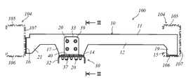
- FIG. 1 is a perspective view of the mounting unit 100
- FIG. 2 is a side view of the mounting unit 100
- FIG. 3 is a cross-sectional view taken along the line III-III in FIG.
- the left-right direction on the paper is the vehicle longitudinal direction
- the direction perpendicular to the paper is the vehicle width direction.
- the right side of FIG. 2 will be referred to as “front” and the left side of FIG. 2 will be referred to as “rear”.
- the mounting unit 100 is for mounting the underfloor device 103 to the underframe 102 of the railway vehicle 101.
- attachment units 100 are provided between the plurality of horizontal beams 104 corresponding to the underfloor equipment 103 to be arranged.
- the mounting unit 100 includes a mounting beam member 10 that spans a transverse beam 104 (see FIG. 2) disposed in the front and rear, and a mounting bracket 30 that is fixed to the mounting beam member and supports the underfloor device 103. And.
- the mounting beam member 10 and the mounting bracket 30 will be described in order.
- the mounting beam member 10 is formed by bending a plate material, and includes an upper plate portion 11 extending in the vehicle longitudinal direction, and a first side plate portion 12 and a second side plate located on both sides of the upper plate portion 11 in the vehicle width direction. Part 13 (see FIG. 3), a protruding part 14 projecting horizontally from the lower end of the first side plate part 12, a first connecting part 15 provided in the front part, and a second connecting part provided in the rear part. 16.
- the first side plate portion 12 has a trapezoidal extending portion 17 whose size in the vehicle longitudinal direction decreases downward.
- the protruding portion 14 extends in the horizontal direction continuously from the lower end of the extending portion 17.
- the protrusion part 14 is integrally formed with the attachment beam member 10 (1st side board part 12).
- a fastening hole 18 penetrating in the vertical direction is formed in the central portion of the protruding portion 14. 1 and 2, the protrusion 14 is provided at a position closer to one end from the longitudinal center of the mounting beam member 10, but is not limited to the illustrated position, and the protrusion 14 is not provided. You may provide in several places.
- the first connecting portion 15 is a portion that is connected to the front cross beam 104
- the second connecting portion is a portion that is connected to the rear cross beam 104.
- the cross beam 104 of the present embodiment includes an upper plate portion 105, a bottom plate portion 106 that faces the upper plate portion 105 and is located below the upper plate portion 105, and the upper plate portion 105 and the bottom plate portion 106. And a side plate portion 107 that connects the front end portions of the two, and has a C-shaped cross section that opens rearward.
- the first side plate portion 12 and the second side plate portion 13 have a leg portion 19 that extends downward in the front portion, and the first connecting portion 15 is connected to the vehicle from the lower end of the leg portion 19. It has a flat plate shape extending outward in the width direction and perpendicular to the vertical direction. As shown in FIG. 2, the 1st connection part 15 contacts the upper surface of the baseplate part 106 of the front cross beam 104, and is being fixed to the cross beam 104 in that state.
- the 2nd connection part 16 and the 2nd side board part 13 have the wide part 21 to which an up-down direction dimension becomes large toward the back in a rear side part, and the 2nd connection part 16 is shown.
- the 2nd connection part 16 contacts the outer surface of the side-plate part 107 of the back horizontal beam 104, and is being fixed to the horizontal beam 104 in that state.
- the mounting bracket 30 includes a first reinforcing member 31 provided on the inner surface side of the mounting beam member 10, a first member 32 positioned below the protruding portion 14, and And a second member 33 located above the protruding portion 14.
- the first reinforcing member 31 is a plate member having an L-shaped cross section, and includes a vertical plate portion 34 extending in the vertical direction and a bottom plate portion 35 extending in the horizontal direction from the lower end of the vertical plate portion 34.
- the first reinforcing member 31 is disposed so that the bottom plate portion 35 is located on the same plane as the protruding portion 14 in the lower portion of the mounting beam member 10.
- the vertical plate portion 34 is fixed to the inner surface of the second side plate portion 13 of the mounting beam member 10 using the fastener 20.
- a blind fastener is used as the fastener 20.
- the first member 32 is a plate member having a C-shaped cross section that opens downward, and includes a first fixing portion 36 and a first support portion 37.
- the first fixing portion 36 is fixed to the bottom plate portion 35 by overlapping from below
- the first support portion 37 is fixed to the protruding portion 14 by overlapping with the protruding portion 14 from below. ing. Any fixation is performed by the fastener 20.
- the first support portion 37 is formed with a fastening hole 38 penetrating in the vertical direction at a position corresponding to the fastening hole 18 of the protruding portion 14.
- the second member 33 is a plate member having an L-shaped cross section, a second fixing portion 39 extending in the vertical direction, and a second support portion 40 extending in the horizontal direction from the lower end of the second fixing portion 39. And have.
- the second fixing portion 39 is overlapped and fixed to the first side plate portion 12 from the side, and the second support portion 40 is overlapped and fixed to the protruding portion 14 from above.
- the second support part 40 is fixed to the projecting part 14 so as to sandwich the projecting part 14 with the first support part 37.
- a fastening hole 41 penetrating in the vertical direction is formed in the second support portion 40 at a position corresponding to the fastening hole 18 of the protruding portion 14.
- the mounting bracket is structured to be attached by welding or the like.
- each component constituting the mounting bracket can be manufactured by machining such as pressing or bending.
- welding is not required or welding can be minimized, so that distortion due to welding does not occur and assembly can be performed with high accuracy.
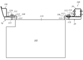
- FIG. 4 is a schematic plan view of the underframe 102 with the underfloor device 103 attached.
- the vertical direction of the paper is the longitudinal direction of the vehicle
- the lower side of the paper is the front
- the upper side of the paper is the rear
- the left-right direction of the paper is the vehicle width direction.
- the underframe 102 is a portion corresponding to the floor of the vehicle body, and is formed of several beam members.
- the side beam 108 and the lateral beam 104 which are beam members constituting the underframe 102 are illustrated.
- the side beams 108 are beam members positioned at both ends in the vehicle width direction and extending in the vehicle longitudinal direction.
- the transverse beams 104 are beam members extending in the vehicle width direction, and a plurality of the transverse beams 104 are arranged at a predetermined interval in the vehicle longitudinal direction.
- the mounting unit 100 is fixed between two transverse beams 104 arranged in the longitudinal direction of the vehicle. In that case, it installs in arbitrary vehicle width direction positions according to the magnitude
- FIG. In addition, when installing the attachment unit 100, since it is not necessary to perform a complicated process to the cross beam 104, a vehicle width direction position can be easily changed according to the magnitude
- the three attachment units 100 are installed on the frame 102, but the number of the attachment units 100 installed on the frame 102 is not particularly limited. When a plurality of mounting units 100 are installed, each mounting unit 100 may be installed at a different position in the vehicle width direction.
- FIG. 5 is a cross-sectional view taken along the line VV in FIG. In FIG. 5, the left-right direction on the paper is the vehicle width direction.
- the underfloor equipment 103 has a mounting arm 109 in the upper part.
- the mounting arm 109 has an L-shaped cross section, and includes a vertical portion 111 that extends upward from the upper surface of the underfloor device main body 110 and a horizontal portion 112 that extends in the horizontal direction from the upper end of the vertical portion 111.
- a fastening hole 113 is formed in the horizontal portion 112.
- the mounting arm 109 of this embodiment is formed in an L-shaped cross section, the mounting arm 109 may have a Z-shaped cross section having a horizontal portion 112, and the shape is not limited thereto.
- the horizontal portion 112 of the mounting arm 109 is placed on the upper surface of the second member 33 of the mounting bracket 30.
- the fastening bolt 114 is passed through the fastening hole 113 of the mounting arm 109, the fastening hole 41 of the second member 33, the fastening hole 18 of the protruding portion 14, and the fastening hole 38 of the first member 32 from the top in this order ( (See FIG. 3).
- the fastening nut 115 is tightened from the lower end of the fastening bolt 114.
- the underfloor device 103 is attached to the frame 102 of the railcar 101 via the attachment unit 100.
- FIG. 6 is a cross-sectional view of the mounting unit 200 according to the present embodiment, and corresponds to FIG. 3 of the first embodiment.
- the protruding portion 14 is formed integrally with the mounting beam member 10
- the protruding portion 52 is different from the mounting beam member 10. Formed in the body.
- the second embodiment will be described focusing on differences from the first embodiment.
- the mounting unit 200 according to the present embodiment includes the mounting beam member 10 and the mounting bracket 30 in the same manner as the mounting unit 100 according to the first embodiment.
- the mounting beam member 10 of the present embodiment is similar to the mounting beam member 10 of the first embodiment in that the upper plate portion 11, the first side plate portion 12, the second side plate portion 13, and the first connecting portion 15.
- the protruding portion 14 is not provided. That is, the mounting beam member 10 of the present embodiment is configured in the same manner as the mounting beam member 10 of the first embodiment, except that the protruding beam 14 is not provided.
- the mounting bracket 30 of this embodiment has the 1st reinforcement member 31, the 1st member 32, and the 2nd member 33 similarly to the mounting bracket 30 of 1st Embodiment, Furthermore, 1st Embodiment
- the mounting member 30 has a third member 50 that the mounting bracket 30 does not have.
- the first reinforcing member 31, the first member 32, and the second member 33 of the present embodiment have basically the same configuration as that of the first embodiment.
- the third member 50 is a plate member having an L-shaped cross section, and has a third fixing portion 51 extending in the vertical direction and a protruding portion 52 extending in the horizontal direction from the lower end of the third fixing portion 51.
- the third fixing portion 51 is fixed to the outer surface of the first side plate portion 12 while being sandwiched between the second fixing portion 39 of the second member 33 and the first side plate portion 12 of the mounting beam member 10.
- the protruding portion 52 is fixed to each other in a state of being sandwiched between the first support portion 37 of the first member 32 and the second support portion 40 of the second member 33.
- the protruding portion 52 is separated from the mounting beam member 10 as in this embodiment. It may be a body. If the protruding portion 52 is separated from the mounting beam member 10 as in the present embodiment, the position of the protruding portion 52 in the vehicle longitudinal direction is changed according to the size of the underfloor device 103 and the like. It is also possible to change the vehicle longitudinal position.
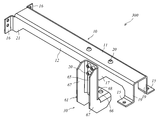
- FIG. 7 is a perspective view of the mounting unit 300
- FIG. 8 is a side view of the mounting unit 300
- FIG. 9 is a cross-sectional view taken along the line IX-IX in FIG.
- the vehicle of the main body portion (upper plate portion 105, first side plate portion 12, and second side plate portion 13) of the mounting beam member 10 extending from the front side beam 104 to the rear side beam 104.
- the underfloor device 103 is supported on the outer side in the width direction
- the attachment unit 300 according to the present embodiment supports the underfloor device 103 below the main body.
- the third embodiment will be described with a focus on differences from the first embodiment.
- the mounting unit 300 includes the mounting beam member 10 and the mounting bracket 30 in the same manner as the mounting unit 100 according to the first embodiment.
- the mounting beam member 10 includes the upper plate portion 11, the first side plate portion 12, the second side plate portion 13, the first connecting portion 15, and the second connecting portion, as in the case of the first embodiment. 16, but does not have the protruding portion 14 (see FIG. 1 and the like) that the mounting beam member 10 of the first embodiment has.
- the first side plate portion 12 has an extending portion 17, whereas the second side plate portion 13 does not have an extending portion 17.
- the mounting bracket 30 of the present embodiment has a shape different from that of the mounting bracket 30 of the first embodiment.
- the mounting bracket 30 of the present embodiment includes a second reinforcing member 60 positioned inside the mounting beam member 10 and a fourth member 61 for supporting the underfloor device 103.
- the second reinforcing member 60 is made of a plate material, extends in the vertical direction and is fixed to the inner surface of the first side plate portion 12 of the mounting beam member 10, and both sides of the vertical plate portion 62 in the vehicle longitudinal direction.
- Two side plates 63 that are positioned and perpendicular to the longitudinal direction of the vehicle, and two horizontal plates that extend outward from the upper end of each side plate 63 in the longitudinal direction of the vehicle and are fixed to the inner surface of the upper plate 11 of the mounting beam member 10 Part 64 (see also FIG. 8).
- the fourth member 61 includes a fourth fixing portion 65 that extends in the vertical direction and has an upper portion fixed to overlap with the outer surface of the first side plate portion 12 of the mounting beam member 10 from the side, and a fourth fixing portion.
- a fourth support portion 66 extending horizontally from the lower end of 65 and positioned below the mounting beam member 10, and L-shaped side plate portions positioned on both sides of the fourth fixing portion 65 and the fourth support portion 66 in the longitudinal direction of the vehicle 67.
- a through hole 68 penetrating in the vertical direction is formed in the central portion of the fourth support portion 66.
- the underfloor device 103 is placed on the upper surface of the fourth support portion 66, and the underfloor device 103 is fixed to the fourth support portion 66 using the fastening bolts 114 and the fastening nuts 115 described above.
- the main body portion of the mounting beam member 10 has a C-shaped cross section that opens downward. It is not limited to such a shape.
- the mounting beam member 10 may have a C-shaped cross section that opens upward or laterally, or may have a rectangular frame shape with no opening.
- the bottom plate portion 35 that fixes the first member 32 is included in the mounting beam member 10 (is formed integrally), and thus the first reinforcing member 31 is omitted. be able to.
- the second member 33 may be pressed so that the central portion is convex in the thickness direction.
- the protruding portion 14 of the mounting beam member 10 can be omitted in the first embodiment, and the third member 50 is omitted in the second embodiment. be able to.
- the protrusion 14 is pressed so that the central portion is convex in the thickness direction in the first embodiment, and the protrusion 52 is pressed so that the central portion is convex in the thickness direction in the second embodiment.
- the second member 33 can be omitted.
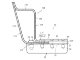
- FIG. 10 is a side view of the mounting bracket 70 according to the present embodiment.
- the left-right direction on the paper is the vehicle width direction
- the direction perpendicular to the paper is the vehicle longitudinal direction.
- the mounting bracket 30 according to the first to third embodiments is fixed to the mounting beam member 10
- the mounting bracket 70 according to the present embodiment is fixed to the side beam 108.
- the side beam 108 of the present embodiment is formed by connecting a lower beam member 116 having an L-shaped cross section and an upper beam member 117 having a substantially S-shaped cross section, and has a rectangular frame shape as a whole in cross section. It is the beam member which has.
- the lower beam member 116 includes an outer plate 118 located on the vehicle width direction end portion side of the frame 102 (hereinafter referred to as “vehicle width direction outside”), and a vehicle on the frame 102 from the lower end of the outer plate 118.
- the upper beam member 117 includes an upper plate portion 121 that faces the bottom plate portion 119, an inner plate portion 122 that extends downward from an inner end in the vehicle width direction of the upper plate portion 121, and a lower end direction of the inner plate portion 122 in the vehicle width direction. And an upper beam protrusion 123 that extends inward and contacts the lower beam protrusion 120.
- the lower beam protrusion 120 and the upper beam protrusion 123 constitute a protrusion 124.
- the mounting bracket 70 includes a first member 32 and a second member 33.
- the first member 32 is formed in the same manner as the first member 32 of the first to third embodiments, and is fixed to the bottom plate portion 119 of the side beam 108 by being overlapped and fixed from below.
- a first support portion 37 positioned below the protruding portion 124 of the side beam 108.
- the first support portion 37 of the present embodiment has a vehicle width direction dimension larger than that of the protruding portion 124, and a tip end portion thereof is positioned on the inner side of the protruding portion 124 in the vehicle width direction.
- a fastening hole 38 penetrating in the vertical direction is formed in the central portion of the first support portion 37.
- the second member 33 is not formed in an L-shaped cross section like the second member 33 of the first to third embodiments, but is formed in a flat plate shape as a whole. That is, the second member 33 of the present embodiment has the second support portion 40 but does not have the second fixing portion 39 (see FIG. 1 and the like).
- the second support portion 40 is located above the protruding portion 124 of the side beam 108.
- the second support portion 40 is larger in dimension in the vehicle width direction than the protruding portion 124, and the tip end portion is located on the inner side in the vehicle width direction than the protruding portion 124.
- the second support part 40 overlaps the protrusion 124 from above, and is fixed to the protrusion 124 so as to sandwich the protrusion 124 with the first support part 37. Further, a fastening hole 41 is formed at a position corresponding to the fastening hole 38 of the first support portion 37 in the center portion of the second support portion 40.
- a spacer 125 having the same thickness as the protruding portion 124 is inserted between the tip portion of the first support portion 37 and the tip portion of the second support portion 40.
- the spacer 125 may be disposed avoiding the fastening holes 38 and 41 so as not to interfere with a fastening bolt 114 described later, or a through hole may be formed at a position corresponding to the fastening holes 38 and 41. Even when the fastening bolt 114 is tightened by inserting the spacer 125 between the tip portion of the first support portion 37 and the tip portion of the second support portion 40, the distance between the first support portion 37 and the second support portion 40. Is kept constant, and the first member 32 and the second member 33 can be prevented from being distorted.
- FIG. 5 described above also shows a method of mounting the underfloor device 103 using the mounting bracket 70.
- the horizontal portion 112 of the mounting arm 109 is placed on the upper surface of the second member 33 of the mounting bracket 70.
- the fastening bolt 114 is penetrated from above in the order of the fastening hole 113 of the mounting arm 109, the fastening hole 41 of the second member 33, and the fastening hole 38 of the first member 32 (see FIG. 10).
- the fastening nut 115 is tightened from the lower end of the fastening bolt 114.
- the underfloor device 103 is attached to the underframe 102 of the railway vehicle 101 via the attachment fitting 70.
- the mounting bracket 70 according to the present embodiment, it is not necessary to perform complicated processing on the side beam 108 when the mounting bracket 70 is fixed to the side beam 108. Therefore, the position of the mounting bracket 70 in the vehicle longitudinal direction can be easily changed according to the size of the underfloor device 103 (see FIG. 4).
- FIG. 11 is a side view of the mounting bracket 80 according to the present embodiment.
- the left-right direction on the paper is the vehicle longitudinal direction
- the direction perpendicular to the paper is the vehicle width direction
- the left side of the paper is the front
- the right side of the paper is the rear.
- the mounting bracket 70 according to the present embodiment is fixed to the cross beam 104.
- the cross beam 104 has the upper plate portion 105, the bottom plate portion 106, and the side plate portion 107, and is formed in a C-shaped cross section that opens rearward.
- the mounting bracket 80 according to the present embodiment has basically the same structure as the mounting bracket 30 according to the second embodiment, except that the mounting bracket 80 is fixed to the cross beam 104.
- the mounting bracket 80 according to the present embodiment includes a first member 32, a second member 33, and a third member 50, of which the first member 32 is a transverse beam at the first fixing portion 36. 104, the third fixing portion 51 of the third member 50 and the second fixing portion 39 of the second member 33 are overlapped on the side plate portion 107 of the lateral beam 104 from the side. Is fixed.
- the second support part 40 is fixed to the protrusion part 52 with the protrusion part 52 sandwiched between the first support part 37 and supports the underfloor device 103 on the upper surface thereof.
- the mounting bracket according to the first to fifth embodiments is a mounting bracket for mounting an underfloor device on a railcar frame having a beam member, and protrudes in the horizontal direction at the lower end portion of the beam member and A first member positioned below the protrusion, which is integral with or separate from the member, and a second member positioned above the protrusion, and the first member is fixed to the protrusion overlapping from below
- the second support part has a second support part that is fixed to the protrusion part from above, and the second support part protrudes between the first support part. Support the underfloor equipment on the top surface with the part in between.
- This configuration makes it possible to set the fixed position relatively freely, so that it can be used regardless of the underfloor equipment and the vehicle type, and is highly versatile. Therefore, it is preferable in terms of work efficiency and cost.
- the mounting bracket can be arranged according to the size of the underfloor equipment, it is not necessary to provide a member or the like that is not originally necessary for the underframe, and an increase in the weight of the underframe can be suppressed.
- the first member has a first fixing portion separately from the first support portion, and the first fixing portion is a lower portion of the beam member.
- the bottom plate portion that is integral with or separate from the beam member that is located on the same plane as the protruding portion is overlapped and fixed from below.
- the second member has a second fixing portion separately from the second support portion, and the second fixing portion is positioned above the protruding portion. It overlaps and fixes from the side with respect to the side-plate part of the beam member to perform.
- the mounting bracket according to the second and fifth embodiments further includes a third member that is a separate member from the first member and has a protruding portion, and the third member extends vertically upward from the protruding portion.
- the third fixing portion is fixed to the side plate portion of the beam member, and the second supporting portion, the protruding portion, and the first supporting portion are viewed from above. They are fixed in one piece in this order.
- the third member including the projecting portion is formed in an L-shaped cross section, so that when the underfloor device is placed above the projecting portion, Deformation of the proximal end portion can be suppressed, and as a result, the underfloor equipment can be prevented from tilting.
- the mounting unit is a mounting unit that is provided between at least two horizontal beams extending in the vehicle width direction and that can mount an underfloor device via a mounting bracket.
- a mounting beam member that extends in the longitudinal direction of the vehicle, and a mounting bracket that is fixed to the mounting beam member and that attaches the underfloor equipment to the undercarriage of the railway vehicle.
- the first member has a first support part that is fixed by being overlapped from below with respect to the part, and the second member has a second support part that is fixed by being overlapped with respect to the protruding part from above.
- the mounting bracket is disposed at any position in the vehicle width direction. be able to. Therefore, it is possible to improve the degree of design freedom regarding the arrangement of the underfloor equipment.
- the mounting beam member includes an upper plate portion, a bottom plate portion, and a side plate portion that connects one end portions of the upper plate portion and the bottom plate portion in the vehicle longitudinal direction, And can be installed between two transverse beams that are formed in a C-shaped cross section and open to the other in the longitudinal direction of the vehicle, and the mounting beam member is a bottom plate portion of one of the two transverse beams. It has the 1st connection part connectable with an upper surface, and the 2nd connection part connectable with the outer surface of the side-plate part of the other horizontal beam.
- the first connecting portion and the second connecting portion for connecting the mounting beam member to the cross beam have different structures to prevent the mounting beam member from falling off even when a load is applied from various directions. be able to.
- the first connecting portion is connected to the upper surface of the bottom plate portion of the cross beam, even if the fastener that connects the first connecting portion and the cross beam is damaged, it is possible to prevent the mounting beam member from falling off. it can.
- the mounting unit according to the third embodiment is a mounting unit that is provided between at least two horizontal beams extending in the vehicle width direction and can be used to mount an underfloor device via a mounting bracket.
- a mounting beam member disposed in the longitudinal direction of the vehicle, and a mounting bracket fixed to the mounting beam member for mounting an underfloor device to the undercarriage of the railway vehicle.
- the mounting beam member is disposed between the two horizontal beams.
- the mounting bracket is configured to be installed at an arbitrary position in the vehicle width direction, and the mounting bracket is fixed to the mounting beam member by being overlapped from the side, and extends downward from the mounting beam member, and the lower end of the fourth fixing unit A fourth support portion extending in a horizontal direction from the portion and positioned below the attachment beam member.
- the third embodiment can support the underfloor equipment below the beam member.
- the degree of freedom in design can be further improved with respect to the arrangement of the underfloor equipment.
- the mounting unit according to the first and second embodiments interferes with other members other than the underfloor equipment, the interference can be avoided by using the mounting unit according to the third embodiment.
- the railway vehicle according to the first to fifth embodiments includes the above-described mounting unit and the underfloor equipment supported by the mounting unit. Therefore, the railway vehicle according to the first to fifth embodiments can achieve the effects described above.
- the underfloor device has a mounting arm including a horizontal portion, and the horizontal portion is fixed to the upper surface of the mounting bracket.
- the load of the underfloor equipment is applied to the upper surface side of each mounting bracket, and the load in the pulling direction is not applied to the fastening bolt. Therefore, the fastening bolt is not easily damaged, and even if the fastening bolt is damaged or the fastening nut is loosened and dropped off, the underfloor equipment is not supported by each mounting bracket and does not drop off immediately.
- Mounting beam members (beam members) 12 First side plate (side plate) 14 projecting portion 15 first connecting portion 16 second connecting portion 30 mounting bracket 32 first member 33 second member 35 bottom plate portion 36 first fixing portion 37 first supporting portion 39 second fixing portion 40 second supporting portion 50 third Member 51 Third fixing portion 52 Protruding portion 61 Fourth member 65 Fourth fixing portion 66 Fourth support portion 70 Mounting bracket 80 Mounting bracket 100 Mounting unit 101 Rail vehicle 102 Underframe 103 Underfloor equipment 104 Cross beam (beam member) 106 Bottom plate portion 107 Side plate portion 108 Side beam (beam member) 109 Mounting arm 119 Bottom plate portion 124 Projection 200 Mounting unit 300 Mounting unit 300 Mounting unit
Landscapes
- Engineering & Computer Science (AREA)
- Mechanical Engineering (AREA)
- Automation & Control Theory (AREA)
- Transportation (AREA)
- Life Sciences & Earth Sciences (AREA)
- Wood Science & Technology (AREA)
- Connection Of Plates (AREA)
- Body Structure For Vehicles (AREA)
Abstract
Description
まず、第1実施形態に係る取付ユニット100について説明する。図1は取付ユニット100の斜視図であり、図2は取付ユニット100の側面図であり、図3は図2のIII-III矢視断面図である。図2において、紙面左右方向が車両長手方向であり、紙面に対して垂直な方向が車幅方向である。なお、以下では、便宜上、図2の紙面右を「前」と称し、紙面左を「後」と称して説明する。
取付梁部材10は、板材を曲げ加工することにより形成されており、車両長手方向に延びる上板部11と、上板部11の車幅方向両側に位置する第1側板部12及び第2側板部13(図3参照)と、第1側板部12の下端から水平方向に突出する突出部14と、前方部分に設けられた第1連結部15と、後方部分に設けられた第2連結部16と、を有している。
本実施形態に係る取付金具30は、図3で示すように、上記の取付梁部材10の内面側に設けられる第1補強部材31と、突出部14の下方に位置する第1部材32と、突出部14の上方に位置する第2部材33と、を有している。
続いて、取付ユニット100の使用方法について説明する。図4は、床下機器103が取り付けられた状態の台枠102の概略平面図である。図4において、紙面上下方向が車両長手方向であり、紙面下方が前方であり、紙面上方が後方であり、紙面左右方向が車幅方向である。台枠102は、車体の床にあたる部分であって、いくつかの梁部材によって形成されている。図4では、台枠102を構成する梁部材である側梁108と横梁104を図示している。側梁108は、車幅方向の両端に位置しており、車両長手方向に延びる梁部材である。また、横梁104は、車幅方向に延びる梁部材であって、車両長手方向に所定の間隔をおいて複数配置されている。
次に、第2実施形態に係る取付ユニット200について説明する。図6は、本実施形態に係る取付ユニット200の断面図であって、第1実施形態の図3に相当する。第1実施形態に係る取付ユニット100では、突出部14が取付梁部材10と一体に形成されていたのに対し、本実施形態に係る取付ユニット200では、突出部52が取付梁部材10と別体に形成されている。以下、第2実施形態について第1実施形態との相違点を中心に説明する。
次に、第3実施形態に係る取付ユニット300について説明する。図7は取付ユニット300の斜視図であり、図8は取付ユニット300の側面図であり、図9は図8のIX-IX矢視断面図である。第1実施形態に係る取付ユニット100では、前方の横梁104から後方の横梁104まで延びる取付梁部材10の本体部(上板部105、第1側板部12、及び第2側板部13)の車幅方向外側において床下機器103を支持していたのに対し、本実施形態に係る取付ユニット300では本体部の下方において床下機器103を支持している。以下、第3実施形態について第1実施形態との相違点を中心に説明する。
上述した第1乃至3実施形態に係る取付ユニット100、200、300では、取付梁部材10の本体部分が下方に開口する断面C字状の形状を有していたが、取付梁部材10はこのような形状に限定されない。例えば、取付梁部材10は、上方や側方に開口する断面C字状の形状を有していてもよく、開口部分がない断面矩形枠状の形状を有していてもよい。これらの場合、第1及び2実施形態において、第1部材32を固定する底板部35が取付梁部材10に含まれる(一体に形成される)ことになるため、第1補強部材31を省略することができる。
次に、第4実施形態に係る取付金具70について説明する。図10は、本実施形態に係る取付金具70の側面図である。図10において、紙面左右方向が車幅方向であり、紙面に対して垂直な方向が車両長手方向である。第1乃至3実施形態に係る取付金具30は、取付梁部材10に固定されているのに対し、本実施形態に係る取付金具70は、側梁108に固定されている。
次に、第5実施形態に係る取付金具80について説明する。図11は、本実施形態に係る取付金具80の側面図である。図11において、紙面左右方向が車両長手方向であり、紙面に対して垂直な方向が車幅方向であり、紙面左方が前方であり、紙面右方が後方である。本実施形態に係る取付金具70は、横梁104に固定される。横梁104は、上述したとおり上板部105と、底板部106と、側板部107と、を有しており、後方に開口する断面C字状に形成されている。
以上のとおり、第1乃至5実施形態に係る取付金具は、梁部材を有する鉄道車両の台枠に床下機器を取り付けるための取付金具であって、梁部材の下端部分において水平方向に突出しかつ梁部材と一体又は別体である突出部の下方に位置する第1部材と、突出部の上方に位置する第2部材と、を備え、第1部材は、突出部に対して下方から重ねて固定される第1支持部を有し、第2部材は、突出部に対して上方から重ねて固定される第2支持部を有し、第2支持部は、第1支持部との間で突出部を挟んだ状態で、その上面で床下機器を支持する。
12 第1側板部(側板部)
14 突出部
15 第1連結部
16 第2連結部
30 取付金具
32 第1部材
33 第2部材
35 底板部
36 第1固定部
37 第1支持部
39 第2固定部
40 第2支持部
50 第3部材
51 第3固定部
52 突出部
61 第4部材
65 第4固定部
66 第4支持部
70 取付金具
80 取付金具
100 取付ユニット
101 鉄道車両
102 台枠
103 床下機器
104 横梁(梁部材)
106 底板部
107 側板部
108 側梁(梁部材)
109 取付アーム
119 底板部
124 突出部
200 取付ユニット
300 取付ユニット
Claims (9)
- 梁部材を有する鉄道車両の台枠に床下機器を取り付けるための取付金具であって、
前記梁部材の下端部分において水平方向に突出しかつ前記梁部材と一体又は別体である突出部の下方に位置する第1部材と、
前記突出部の上方に位置する第2部材と、を備え、
前記第1部材は、前記突出部に対して下方から重ねて固定される第1支持部を有し、
前記第2部材は、前記突出部に対して上方から重ねて固定される第2支持部を有し、
前記第2支持部は、前記第1支持部との間で前記突出部を挟んだ状態で、その上面で前記床下機器を支持する、取付金具。 - 前記第1部材は、前記第1支持部とは別に第1固定部を有し、
前記第1固定部は、前記梁部材の下方部分において前記突出部と同一平面上に位置する前記梁部材と一体又は別体である底板部に対し、下方から重ねて固定されている、請求項1に記載の取付金具。 - 前記第2部材は、前記第2支持部とは別に第2固定部を有し、
前記第2固定部は、前記突出部よりも上方に位置する前記梁部材の側板部に対し、側方から重ねて固定されている、請求項1又は2に記載の取付金具。 - 前記第1部材とは別体であって前記突出部を有する第3部材をさらに備え、
前記第3部材は、前記突出部から鉛直方向上方に延びる第3固定部を有して断面L字状に形成されており、
前記第3固定部は、前記梁部材の側板部に固定されており、
前記第2支持部、前記突出部、及び前記第1支持部は、上方からこの順で重ねて一体に固定されている、請求項1乃至3のうちいずれか一の項に記載の取付金具。 - 車幅方向に延びる、少なくとも2つの横梁の間に設けられ、取付金具を介して床下機器を取付可能な取付ユニットであって、
前記2つの横梁の間に配置され、車両長手方向に延びる取付梁部材と、
前記取付梁部材に固定され、鉄道車両の台枠に床下機器を取り付けるための取付金具と、を備え、
前記取付金具は、前記取付梁部材の下端部分において水平方向に突出しかつ前記取付梁部材と一体又は別体の突出部の下方に位置する第1部材と、
前記突出部の上方に位置する第2部材と、を備え、
前記第1部材は、前記突出部に対して下方から重ねて固定される第1支持部を有し、
前記第2部材は、前記突出部に対して上方から重ねて固定される第2支持部を有し、
前記第2支持部は、前記第1支持部との間で前記突出部を挟んだ状態で、その上面で前記床下機器を支持し、
前記取付梁部材は、前記2つの横梁の間において任意の車幅方向位置に設置可能に構成されている、取付ユニット。 - 前記取付梁部材は、上板部と、底板部と、前記上板部及び前記底板部の車両長手方向の一方の端部同士をつなぐ側板部と、を有して、車両長手方向の他方に開口する断面C字状に形成された2つの横梁の間に設置可能であって、
前記取付梁部材は、前記2つの横梁のうち一方の横梁の底板部の上面に連結可能な第1連結部と、他方の横梁の側板部の外面に連結可能な第2連結部とを有している、請求項5に記載の取付ユニット。 - 車幅方向に延びる、少なくとも2つの横梁の間に設けられ、取付金具を介して床下機器を取付可能な取付ユニットであって、
前記2つの横梁の間に配置され、車両長手方向に延びる取付梁部材と、
前記取付梁部材に固定され、鉄道車両の台枠に床下機器を取り付けるための取付金具と、を備え、
前記取付梁部材は、前記2つの横梁の間において任意の車幅方向位置に設置可能に構成され、
前記取付金具は、前記取付梁部材に対し側方から重ねて固定され前記取付梁部材から下方に向かって延びる第4固定部と、前記第4固定部の下端部分から水平方向に延びて前記取付梁部材の下方に位置する第4支持部と、を有する、取付ユニット。 - 請求項5乃至7のうちいずれか一の項に記載の取付ユニットと、前記取付ユニットに支持された床下機器と、を備えた鉄道車両。
- 前記床下機器は、水平部を含む取付アームを有し、
前記水平部は、前記取付金具の上面に固定されている、請求項8に記載の鉄道車両。
Priority Applications (5)
| Application Number | Priority Date | Filing Date | Title |
|---|---|---|---|
| PCT/JP2015/001057 WO2016135782A1 (ja) | 2015-02-27 | 2015-02-27 | 取付金具、取付ユニット、及び鉄道車両 |
| JP2017501548A JP6523426B2 (ja) | 2015-02-27 | 2015-02-27 | 取付金具、取付ユニット、及び鉄道車両 |
| US15/553,865 US10549764B2 (en) | 2015-02-27 | 2015-02-27 | Attaching metal fitting, attaching unit, and railcar |
| CN201580076843.2A CN107249958B (zh) | 2015-02-27 | 2015-02-27 | 安装件、安装单元、以及铁道车辆 |
| TW104109880A TWI554421B (zh) | 2015-02-27 | 2015-03-27 | Installation of metal parts, installation units, and railway vehicles |
Applications Claiming Priority (1)
| Application Number | Priority Date | Filing Date | Title |
|---|---|---|---|
| PCT/JP2015/001057 WO2016135782A1 (ja) | 2015-02-27 | 2015-02-27 | 取付金具、取付ユニット、及び鉄道車両 |
Publications (1)
| Publication Number | Publication Date |
|---|---|
| WO2016135782A1 true WO2016135782A1 (ja) | 2016-09-01 |
Family
ID=56789409
Family Applications (1)
| Application Number | Title | Priority Date | Filing Date |
|---|---|---|---|
| PCT/JP2015/001057 Ceased WO2016135782A1 (ja) | 2015-02-27 | 2015-02-27 | 取付金具、取付ユニット、及び鉄道車両 |
Country Status (5)
| Country | Link |
|---|---|
| US (1) | US10549764B2 (ja) |
| JP (1) | JP6523426B2 (ja) |
| CN (1) | CN107249958B (ja) |
| TW (1) | TWI554421B (ja) |
| WO (1) | WO2016135782A1 (ja) |
Cited By (4)
| Publication number | Priority date | Publication date | Assignee | Title |
|---|---|---|---|---|
| CN106428037A (zh) * | 2016-12-02 | 2017-02-22 | 中车长春轨道客车股份有限公司 | 城铁车辆变压器安装结构 |
| WO2018077861A1 (de) * | 2016-10-27 | 2018-05-03 | Siemens Ag Österreich | Langträgeranordnung für einen wagenkasten eines fahrzeugs |
| CN109941310A (zh) * | 2017-12-20 | 2019-06-28 | 莱尔德科技有限公司 | 用于监测机车车轮尺寸的系统和方法 |
| CN113844472A (zh) * | 2021-08-18 | 2021-12-28 | 中车青岛四方机车车辆股份有限公司 | 用于轨道车辆设备的边梁托挂和轨道车辆设备的安装方法 |
Families Citing this family (6)
| Publication number | Priority date | Publication date | Assignee | Title |
|---|---|---|---|---|
| CN108909747B (zh) * | 2018-06-22 | 2020-01-10 | 中车青岛四方机车车辆股份有限公司 | 横梁及具有其的列车 |
| MX2021008932A (es) * | 2019-01-23 | 2021-08-24 | Trinity Rail Group Llc | Extensiones de vagon para estructura de ancho ampliado. |
| CN112572483B (zh) * | 2019-09-30 | 2022-05-13 | 比亚迪股份有限公司 | 轨道车辆 |
| DE102021214851A1 (de) | 2021-12-21 | 2023-06-22 | Siemens Mobility GmbH | Anordnung und Verfahren zur Befestigung eines Gerüsts |
| CN114248811B (zh) * | 2022-01-07 | 2023-06-23 | 中车唐山机车车辆有限公司 | 一种轨道列车用楼梯结构及轨道列车 |
| CN114368401B (zh) * | 2022-01-07 | 2023-06-23 | 中车唐山机车车辆有限公司 | 一种列车二层地板安装结构及车厢 |
Citations (6)
| Publication number | Priority date | Publication date | Assignee | Title |
|---|---|---|---|---|
| JPS57194861U (ja) * | 1981-06-08 | 1982-12-10 | ||
| JPH0137332Y2 (ja) * | 1983-12-30 | 1989-11-10 | ||
| JPH0441003Y2 (ja) * | 1985-02-27 | 1992-09-25 | ||
| US20030164112A1 (en) * | 2002-03-01 | 2003-09-04 | Martin Laflamme | Undercar assembly for a railcar |
| WO2012116971A1 (de) * | 2011-02-28 | 2012-09-07 | Bombardier Transportation Gmbh | Schienenfahrzeug mit aufnahmeraum unterhalb des bodens |
| EP2508407A1 (de) * | 2011-04-04 | 2012-10-10 | Bombardier Transportation GmbH | Gerüst, insbesondere für elektrische Einrichtungen in einem Schienenfahrzeug, und Verfahren zur Herstellung des Gerüsts |
Family Cites Families (20)
| Publication number | Priority date | Publication date | Assignee | Title |
|---|---|---|---|---|
| JPS5677471U (ja) * | 1979-11-21 | 1981-06-24 | ||
| DE4443003A1 (de) * | 1994-12-02 | 1996-06-05 | Graaff Gmbh | Mit Druckluft betriebene Bremse für klotzgebremste Schienenfahrzeuge |
| US6505564B2 (en) * | 2001-05-23 | 2003-01-14 | National Steel Car Limited | Well car with cross member |
| JP2004130914A (ja) | 2002-10-10 | 2004-04-30 | Nippon Sharyo Seizo Kaisha Ltd | 鉄道車両の台枠構造 |
| US6871903B2 (en) * | 2003-01-28 | 2005-03-29 | Kawasaki Jukogyo Kabushiki Kaisha | Structural element and body structure including the same |
| CN100381651C (zh) | 2003-05-20 | 2008-04-16 | 积水化学工业株式会社 | 组合式建筑物 |
| JP4718792B2 (ja) * | 2003-05-20 | 2011-07-06 | 積水化学工業株式会社 | ユニット建物 |
| CN201400172Y (zh) * | 2009-05-14 | 2010-02-10 | 南车青岛四方机车车辆股份有限公司 | 高速轨道车辆水箱安装结构 |
| JP5697953B2 (ja) * | 2010-11-08 | 2015-04-08 | 川崎重工業株式会社 | 鉄道車両の床構造 |
| JP5583553B2 (ja) * | 2010-11-08 | 2014-09-03 | 川崎重工業株式会社 | 鉄道車両の台枠構造 |
| JP5141795B2 (ja) * | 2011-06-20 | 2013-02-13 | 株式会社豊田自動織機 | 車両用バッテリユニット装着装置 |
| CN202429204U (zh) | 2011-12-27 | 2012-09-12 | 南车南京浦镇车辆有限公司 | 车下设备安装座 |
| US9475506B2 (en) * | 2012-02-10 | 2016-10-25 | Nippon Sharyo, Ltd. | Rolling stock |
| CN102808535B (zh) * | 2012-08-23 | 2014-05-07 | 宁波邦达智能停车设备股份有限公司 | 一种载车盘结构 |
| CN203158077U (zh) * | 2013-03-26 | 2013-08-28 | 中国重汽集团济宁商用车有限公司 | 重型卡车限位支架 |
| CN203427803U (zh) * | 2013-08-30 | 2014-02-12 | 南车南京浦镇车辆有限公司 | 轨道车辆底架设备吊挂梁 |
| US10029709B2 (en) * | 2013-11-12 | 2018-07-24 | Kawasaki Jukogyo Kabushiki Kaisha | Railcar |
| CN204150113U (zh) * | 2014-10-11 | 2015-02-11 | 云南力帆骏马车辆有限公司 | 一种兼有副车架功能的异形纵梁自卸汽车车架 |
| CN107249960B (zh) * | 2015-02-27 | 2019-08-30 | 川崎重工业株式会社 | 铁道车辆 |
| SG11201707601YA (en) * | 2015-03-20 | 2017-10-30 | Kawasaki Heavy Ind Ltd | Railcar |
-
2015
- 2015-02-27 CN CN201580076843.2A patent/CN107249958B/zh active Active
- 2015-02-27 WO PCT/JP2015/001057 patent/WO2016135782A1/ja not_active Ceased
- 2015-02-27 US US15/553,865 patent/US10549764B2/en active Active
- 2015-02-27 JP JP2017501548A patent/JP6523426B2/ja not_active Expired - Fee Related
- 2015-03-27 TW TW104109880A patent/TWI554421B/zh not_active IP Right Cessation
Patent Citations (6)
| Publication number | Priority date | Publication date | Assignee | Title |
|---|---|---|---|---|
| JPS57194861U (ja) * | 1981-06-08 | 1982-12-10 | ||
| JPH0137332Y2 (ja) * | 1983-12-30 | 1989-11-10 | ||
| JPH0441003Y2 (ja) * | 1985-02-27 | 1992-09-25 | ||
| US20030164112A1 (en) * | 2002-03-01 | 2003-09-04 | Martin Laflamme | Undercar assembly for a railcar |
| WO2012116971A1 (de) * | 2011-02-28 | 2012-09-07 | Bombardier Transportation Gmbh | Schienenfahrzeug mit aufnahmeraum unterhalb des bodens |
| EP2508407A1 (de) * | 2011-04-04 | 2012-10-10 | Bombardier Transportation GmbH | Gerüst, insbesondere für elektrische Einrichtungen in einem Schienenfahrzeug, und Verfahren zur Herstellung des Gerüsts |
Cited By (10)
| Publication number | Priority date | Publication date | Assignee | Title |
|---|---|---|---|---|
| WO2018077861A1 (de) * | 2016-10-27 | 2018-05-03 | Siemens Ag Österreich | Langträgeranordnung für einen wagenkasten eines fahrzeugs |
| AT519330A1 (de) * | 2016-10-27 | 2018-05-15 | Siemens Ag Oesterreich | Langträgeranordnung für einen Wagenkasten eines Fahrzeugs |
| CN109996716A (zh) * | 2016-10-27 | 2019-07-09 | 西门子移动有限责任公司 | 用于车辆的车身的底杆装置 |
| CN109996716B (zh) * | 2016-10-27 | 2022-03-22 | 西门子交通奥地利有限责任公司 | 用于车辆的车身的底杆装置 |
| US11292495B2 (en) | 2016-10-27 | 2022-04-05 | Siemens Mobility Austria Gmbh | Sole bar arrangement for a body of a vehicle |
| AT519330B1 (de) * | 2016-10-27 | 2022-04-15 | Siemens Mobility Austria Gmbh | Langträgeranordnung für einen Wagenkasten eines Fahrzeugs |
| CN106428037A (zh) * | 2016-12-02 | 2017-02-22 | 中车长春轨道客车股份有限公司 | 城铁车辆变压器安装结构 |
| CN109941310A (zh) * | 2017-12-20 | 2019-06-28 | 莱尔德科技有限公司 | 用于监测机车车轮尺寸的系统和方法 |
| CN113844472A (zh) * | 2021-08-18 | 2021-12-28 | 中车青岛四方机车车辆股份有限公司 | 用于轨道车辆设备的边梁托挂和轨道车辆设备的安装方法 |
| CN113844472B (zh) * | 2021-08-18 | 2022-12-09 | 中车青岛四方机车车辆股份有限公司 | 用于轨道车辆设备的边梁托挂和轨道车辆设备的安装方法 |
Also Published As
| Publication number | Publication date |
|---|---|
| TW201630766A (zh) | 2016-09-01 |
| US10549764B2 (en) | 2020-02-04 |
| CN107249958A (zh) | 2017-10-13 |
| JP6523426B2 (ja) | 2019-05-29 |
| US20180043908A1 (en) | 2018-02-15 |
| CN107249958B (zh) | 2022-04-29 |
| JPWO2016135782A1 (ja) | 2017-07-13 |
| TWI554421B (zh) | 2016-10-21 |
Similar Documents
| Publication | Publication Date | Title |
|---|---|---|
| WO2016135782A1 (ja) | 取付金具、取付ユニット、及び鉄道車両 | |
| JP6118123B2 (ja) | 車両のフレーム構造 | |
| US8616653B2 (en) | Frame structure of seat cushion for vehicle seat | |
| CN107128265B (zh) | 电池支承结构 | |
| CN101633371B (zh) | 车身前部结构 | |
| US8678120B2 (en) | Method and apparatus for mounting device in construction machine | |
| EP3470305B1 (en) | Side rail and manufacturing method of side rail | |
| WO2008066046A1 (fr) | Structure avant pour véhicule à cabine avancée | |
| JP6136889B2 (ja) | スタビライザ支持構造 | |
| JP2013049530A (ja) | 連結金具およびそれを備えたカウンターウェイト | |
| JP5748588B2 (ja) | 乗客コンベヤの主枠 | |
| CN110588557B (zh) | 一种雷达支架及车辆 | |
| JP2008260448A (ja) | フロント・アンダーラン・プロテクタの取付構造 | |
| JP6215393B1 (ja) | エレベータのガイドレール構造 | |
| JP6133731B2 (ja) | 取付金具及び鉄道車両 | |
| JP6805591B2 (ja) | 車両用インストルメントパネル | |
| JP5733043B2 (ja) | リヤバンパカバー支持構造 | |
| JP4809274B2 (ja) | インストルメントパネル取付部構造 | |
| JP6867624B2 (ja) | 閉断面構造体 | |
| JP6497905B2 (ja) | 車両用シートの位置決め構造 | |
| JP6727241B2 (ja) | 車両のルーフ構造 | |
| CN108688732B (zh) | 车辆副车架与后地板之间的系线附连件 | |
| JP6805998B2 (ja) | 車両用インストルメントパネル補強構造 | |
| JP2017065611A (ja) | 配線配管類の固定構造 | |
| KR100828617B1 (ko) | 차량용 센터 서포트 브라켓 어셈블리 |
Legal Events
| Date | Code | Title | Description |
|---|---|---|---|
| 121 | Ep: the epo has been informed by wipo that ep was designated in this application |
Ref document number: 15883082 Country of ref document: EP Kind code of ref document: A1 |
|
| ENP | Entry into the national phase |
Ref document number: 2017501548 Country of ref document: JP Kind code of ref document: A |
|
| WWE | Wipo information: entry into national phase |
Ref document number: 15553865 Country of ref document: US |
|
| NENP | Non-entry into the national phase |
Ref country code: DE |
|
| 122 | Ep: pct application non-entry in european phase |
Ref document number: 15883082 Country of ref document: EP Kind code of ref document: A1 |