WO2016136246A1 - 発電システム - Google Patents
発電システム Download PDFInfo
- Publication number
- WO2016136246A1 WO2016136246A1 PCT/JP2016/000962 JP2016000962W WO2016136246A1 WO 2016136246 A1 WO2016136246 A1 WO 2016136246A1 JP 2016000962 W JP2016000962 W JP 2016000962W WO 2016136246 A1 WO2016136246 A1 WO 2016136246A1
- Authority
- WO
- WIPO (PCT)
- Prior art keywords
- power generation
- temperature
- temperature fluid
- fluid
- passage
- Prior art date
- Legal status (The legal status is an assumption and is not a legal conclusion. Google has not performed a legal analysis and makes no representation as to the accuracy of the status listed.)
- Ceased
Links
Images





Classifications
-
- H—ELECTRICITY
- H10—SEMICONDUCTOR DEVICES; ELECTRIC SOLID-STATE DEVICES NOT OTHERWISE PROVIDED FOR
- H10N—ELECTRIC SOLID-STATE DEVICES NOT OTHERWISE PROVIDED FOR
- H10N10/00—Thermoelectric devices comprising a junction of dissimilar materials, i.e. devices exhibiting Seebeck or Peltier effects
- H10N10/10—Thermoelectric devices comprising a junction of dissimilar materials, i.e. devices exhibiting Seebeck or Peltier effects operating with only the Peltier or Seebeck effects
- H10N10/17—Thermoelectric devices comprising a junction of dissimilar materials, i.e. devices exhibiting Seebeck or Peltier effects operating with only the Peltier or Seebeck effects characterised by the structure or configuration of the cell or thermocouple forming the device
-
- B—PERFORMING OPERATIONS; TRANSPORTING
- B01—PHYSICAL OR CHEMICAL PROCESSES OR APPARATUS IN GENERAL
- B01J—CHEMICAL OR PHYSICAL PROCESSES, e.g. CATALYSIS OR COLLOID CHEMISTRY; THEIR RELEVANT APPARATUS
- B01J19/00—Chemical, physical or physico-chemical processes in general; Their relevant apparatus
- B01J19/24—Stationary reactors without moving elements inside
-
- C—CHEMISTRY; METALLURGY
- C10—PETROLEUM, GAS OR COKE INDUSTRIES; TECHNICAL GASES CONTAINING CARBON MONOXIDE; FUELS; LUBRICANTS; PEAT
- C10G—CRACKING HYDROCARBON OILS; PRODUCTION OF LIQUID HYDROCARBON MIXTURES, e.g. BY DESTRUCTIVE HYDROGENATION, OLIGOMERISATION, POLYMERISATION; RECOVERY OF HYDROCARBON OILS FROM OIL-SHALE, OIL-SAND, OR GASES; REFINING MIXTURES MAINLY CONSISTING OF HYDROCARBONS; REFORMING OF NAPHTHA; MINERAL WAXES
- C10G7/00—Distillation of hydrocarbon oils
-
- F—MECHANICAL ENGINEERING; LIGHTING; HEATING; WEAPONS; BLASTING
- F28—HEAT EXCHANGE IN GENERAL
- F28D—HEAT-EXCHANGE APPARATUS, NOT PROVIDED FOR IN ANOTHER SUBCLASS, IN WHICH THE HEAT-EXCHANGE MEDIA DO NOT COME INTO DIRECT CONTACT
- F28D9/00—Heat-exchange apparatus having stationary plate-like or laminated conduit assemblies for both heat-exchange media, the media being in contact with different sides of a conduit wall
- F28D9/0031—Heat-exchange apparatus having stationary plate-like or laminated conduit assemblies for both heat-exchange media, the media being in contact with different sides of a conduit wall the conduits for one heat-exchange medium being formed by paired plates touching each other
- F28D9/0043—Heat-exchange apparatus having stationary plate-like or laminated conduit assemblies for both heat-exchange media, the media being in contact with different sides of a conduit wall the conduits for one heat-exchange medium being formed by paired plates touching each other the plates having openings therein for circulation of at least one heat-exchange medium from one conduit to another
- F28D9/005—Heat-exchange apparatus having stationary plate-like or laminated conduit assemblies for both heat-exchange media, the media being in contact with different sides of a conduit wall the conduits for one heat-exchange medium being formed by paired plates touching each other the plates having openings therein for circulation of at least one heat-exchange medium from one conduit to another the plates having openings therein for both heat-exchange media
-
- F—MECHANICAL ENGINEERING; LIGHTING; HEATING; WEAPONS; BLASTING
- F28—HEAT EXCHANGE IN GENERAL
- F28D—HEAT-EXCHANGE APPARATUS, NOT PROVIDED FOR IN ANOTHER SUBCLASS, IN WHICH THE HEAT-EXCHANGE MEDIA DO NOT COME INTO DIRECT CONTACT
- F28D9/00—Heat-exchange apparatus having stationary plate-like or laminated conduit assemblies for both heat-exchange media, the media being in contact with different sides of a conduit wall
- F28D9/0093—Multi-circuit heat-exchangers, e.g. integrating different heat exchange sections in the same unit or heat-exchangers for more than two fluids
-
- F—MECHANICAL ENGINEERING; LIGHTING; HEATING; WEAPONS; BLASTING
- F28—HEAT EXCHANGE IN GENERAL
- F28F—DETAILS OF HEAT-EXCHANGE AND HEAT-TRANSFER APPARATUS, OF GENERAL APPLICATION
- F28F27/00—Control arrangements or safety devices specially adapted for heat-exchange or heat-transfer apparatus
- F28F27/02—Control arrangements or safety devices specially adapted for heat-exchange or heat-transfer apparatus for controlling the distribution of heat-exchange media between different channels
-
- F—MECHANICAL ENGINEERING; LIGHTING; HEATING; WEAPONS; BLASTING
- F28—HEAT EXCHANGE IN GENERAL
- F28F—DETAILS OF HEAT-EXCHANGE AND HEAT-TRANSFER APPARATUS, OF GENERAL APPLICATION
- F28F3/00—Plate-like or laminated elements; Assemblies of plate-like or laminated elements
- F28F3/08—Elements constructed for building-up into stacks, e.g. capable of being taken apart for cleaning
- F28F3/083—Elements constructed for building-up into stacks, e.g. capable of being taken apart for cleaning capable of being taken apart
-
- H—ELECTRICITY
- H02—GENERATION; CONVERSION OR DISTRIBUTION OF ELECTRIC POWER
- H02N—ELECTRIC MACHINES NOT OTHERWISE PROVIDED FOR
- H02N11/00—Generators or motors not provided for elsewhere; Alleged perpetua mobilia obtained by electric or magnetic means
-
- B—PERFORMING OPERATIONS; TRANSPORTING
- B01—PHYSICAL OR CHEMICAL PROCESSES OR APPARATUS IN GENERAL
- B01J—CHEMICAL OR PHYSICAL PROCESSES, e.g. CATALYSIS OR COLLOID CHEMISTRY; THEIR RELEVANT APPARATUS
- B01J2219/00—Chemical, physical or physico-chemical processes in general; Their relevant apparatus
- B01J2219/00049—Controlling or regulating processes
- B01J2219/00051—Controlling the temperature
- B01J2219/00074—Controlling the temperature by indirect heating or cooling employing heat exchange fluids
- B01J2219/00087—Controlling the temperature by indirect heating or cooling employing heat exchange fluids with heat exchange elements outside the reactor
- B01J2219/00103—Controlling the temperature by indirect heating or cooling employing heat exchange fluids with heat exchange elements outside the reactor in a heat exchanger separate from the reactor
-
- B—PERFORMING OPERATIONS; TRANSPORTING
- B01—PHYSICAL OR CHEMICAL PROCESSES OR APPARATUS IN GENERAL
- B01J—CHEMICAL OR PHYSICAL PROCESSES, e.g. CATALYSIS OR COLLOID CHEMISTRY; THEIR RELEVANT APPARATUS
- B01J2219/00—Chemical, physical or physico-chemical processes in general; Their relevant apparatus
- B01J2219/24—Stationary reactors without moving elements inside
-
- F—MECHANICAL ENGINEERING; LIGHTING; HEATING; WEAPONS; BLASTING
- F01—MACHINES OR ENGINES IN GENERAL; ENGINE PLANTS IN GENERAL; STEAM ENGINES
- F01K—STEAM ENGINE PLANTS; STEAM ACCUMULATORS; ENGINE PLANTS NOT OTHERWISE PROVIDED FOR; ENGINES USING SPECIAL WORKING FLUIDS OR CYCLES
- F01K13/00—General layout or general methods of operation of complete plants
- F01K13/02—Controlling, e.g. stopping or starting
-
- F—MECHANICAL ENGINEERING; LIGHTING; HEATING; WEAPONS; BLASTING
- F01—MACHINES OR ENGINES IN GENERAL; ENGINE PLANTS IN GENERAL; STEAM ENGINES
- F01K—STEAM ENGINE PLANTS; STEAM ACCUMULATORS; ENGINE PLANTS NOT OTHERWISE PROVIDED FOR; ENGINES USING SPECIAL WORKING FLUIDS OR CYCLES
- F01K7/00—Steam engine plants characterised by the use of specific types of engine; Plants or engines characterised by their use of special steam systems, cycles or processes; Control means specially adapted for such systems, cycles or processes; Use of withdrawn or exhaust steam for feed-water heating
- F01K7/16—Steam engine plants characterised by the use of specific types of engine; Plants or engines characterised by their use of special steam systems, cycles or processes; Control means specially adapted for such systems, cycles or processes; Use of withdrawn or exhaust steam for feed-water heating the engines being only of turbine type
-
- F—MECHANICAL ENGINEERING; LIGHTING; HEATING; WEAPONS; BLASTING
- F28—HEAT EXCHANGE IN GENERAL
- F28F—DETAILS OF HEAT-EXCHANGE AND HEAT-TRANSFER APPARATUS, OF GENERAL APPLICATION
- F28F2250/00—Arrangements for modifying the flow of the heat exchange media, e.g. flow guiding means; Particular flow patterns
- F28F2250/06—Derivation channels, e.g. bypass
-
- F—MECHANICAL ENGINEERING; LIGHTING; HEATING; WEAPONS; BLASTING
- F28—HEAT EXCHANGE IN GENERAL
- F28F—DETAILS OF HEAT-EXCHANGE AND HEAT-TRANSFER APPARATUS, OF GENERAL APPLICATION
- F28F2275/00—Fastening; Joining
- F28F2275/02—Fastening; Joining by using bonding materials; by embedding elements in particular materials
-
- F—MECHANICAL ENGINEERING; LIGHTING; HEATING; WEAPONS; BLASTING
- F28—HEAT EXCHANGE IN GENERAL
- F28F—DETAILS OF HEAT-EXCHANGE AND HEAT-TRANSFER APPARATUS, OF GENERAL APPLICATION
- F28F2275/00—Fastening; Joining
- F28F2275/04—Fastening; Joining by brazing
Definitions
- the present invention relates to a power generation system that generates power by a thermoelectric element using a temperature difference between a high-temperature fluid and a low-temperature fluid that is supplied, and that discharges by adjusting at least one of the high-temperature fluid and the low-temperature fluid to a predetermined temperature.
- thermoelectric element that converts thermal energy into electrical energy by the Seebeck effect
- Patent Document 1 a thermoelectric element is sandwiched between a pair of plates having thermal conductivity to form a plate-like thermoelectric generator unit, a plurality of plate-like thermoelectric generator units are stacked, and a high temperature is applied between adjacent plate-like thermoelectric generator units. A hot fluid passage through which fluid flows and a cold fluid passage through which cold fluid flows are formed.
- Such a power generation system is incorporated in a power plant and uses steam after passing through a steam turbine as a high-temperature fluid. Since this power generation system generates power using exhaust heat in the plant, the energy efficiency of the entire plant can be improved.
- Thermoelectric elements have a small electromotive force per element, and are used by connecting many elements in series. However, when the number of thermoelectric elements is increased, the amount of heat exchange between the high temperature fluid and the low temperature fluid increases while passing through the power generation system, and the temperature difference generated in the thermoelectric elements decreases. Since the electromotive force of a thermoelectric element changes depending on the temperature difference generated at both ends, the power generation efficiency per element decreases when the temperature difference is small, and the cost of the power generation system relative to the amount of power generation is reduced. To increase.
- thermoelectric elements included in the power generation system suppress heat exchange between the high temperature fluid and the low temperature fluid, and maintain a large temperature difference generated between the individual thermoelectric elements.
- the amount of heat exchange in the power generation element is small, it becomes impossible to sufficiently cool the discharged high temperature fluid or heat the low temperature fluid, that is, to adjust the temperature.
- an object of the present invention is to improve the power generation efficiency per thermoelectric element in a power generation system including thermoelectric elements, and to enable temperature adjustment of discharged high-temperature fluid or low-temperature fluid. .
- the present invention is a power generation system (1), which includes a power generation module (2) including thermoelectric elements (7A, 7B), a heat exchanger (3), and a high-temperature fluid inlet (4A). ) And a hot fluid outlet (4B), and a hot fluid passage (4) connected between the hot fluid inlet and the hot fluid outlet to the power generation module and the heat exchanger, a cold fluid inlet (5A), and A cryogenic fluid outlet (5B) having a cryogenic fluid passage (5) connected to the power generation module and the heat exchanger between the cryogenic fluid inlet and the cryogenic fluid outlet, the cryogenic fluid passage comprising: A low temperature side bypass passage (5F) that bypasses the power generation module, and a low temperature side flow rate adjustment valve (50) that adjusts the flow rate of the low temperature fluid flowing into the power generation module; Characterized in that the degree of opening controlled based on the temperature difference between the hot fluid and cold fluid immediately after passing through the serial power generation module.
- the high-temperature fluid is supplied by the heat exchanger provided on the downstream side of the power generation module. Cooling or heating the cryogenic fluid can be discharged outside the power generation system. That is, even when the temperature difference between the high-temperature fluid and the low-temperature fluid in the power generation module is maintained relatively large to improve the power generation efficiency in each thermoelectric element, the power generation system is configured by adjusting the temperature of the high-temperature fluid or the low-temperature fluid in the heat exchanger. Can be discharged outside.
- the power generation system of the present invention can be applied to parts where fluid cooling or heating is required in various plants, and can be used in place of a conventional heat exchange system.
- the power generation system of the present invention can be constructed by adding a power generation module upstream of the conventional heat exchange system, and can be easily applied to existing facilities.
- the configuration of the apparatus can be simplified.
- the high temperature fluid and the low temperature fluid are supplied to the power generation module before the heat exchanger, the temperature difference between the high temperature fluid and the low temperature fluid in the power generation module can be increased.
- the flow rate of the low temperature fluid supplied to the power generation module is adjusted so that the temperature difference between the high temperature fluid and the low temperature fluid at the outlet of the power generation module exceeds a predetermined value. Can be maintained.
- the high-temperature fluid passage has a high-temperature side bypass passage (4F) that bypasses the power generation module and a high-temperature side flow control valve (55) that adjusts the flow rate of the high-temperature fluid flowing into the power generation module.
- the opening degree of the high temperature side flow rate control valve is preferably controlled based on a temperature difference between the high temperature fluid and the low temperature fluid immediately after passing through the power generation module.
- the flow rate of the high temperature fluid supplied to the power generation module is adjusted so that the temperature difference between the high temperature fluid and the low temperature fluid at the outlet of the power generation module is adjusted. It can be maintained above a predetermined value.
- a power generation system (1) which is a power generation module (2) including thermoelectric elements (7A, 7B), a heat exchanger (3), and a high-temperature fluid inlet (4A).
- a hot fluid passage (4) connected to the power generation module and the heat exchanger between the hot fluid inlet and the hot fluid outlet, a cold fluid inlet (5A) and a cold fluid
- a cryogenic fluid passage (5) provided with a fluid outlet (5B) and connected to the power generation module and the heat exchanger between the cryogenic fluid inlet and the cryogenic fluid outlet,
- a high-temperature-side bypass passage (4F) that bypasses the power generation module; and a high-temperature-side flow rate adjustment valve (55) that adjusts the flow rate of the high-temperature fluid flowing into the power generation module.
- the high temperature side bypass passage (4G) may bypass the power generation module and the heat exchanger.
- the high-temperature fluid when the temperature of the high-temperature fluid is low, the high-temperature fluid can be discharged outside without passing through the power generation module and the heat exchanger.
- thermoelectric fluid 141, 151
- temperature regulators 141, 151
- the power generation module it is preferable to further include temperature regulators (141, 151) provided in a portion of the high-temperature fluid passage between the high-temperature fluid inlet and the power generation module to adjust the temperature of the high-temperature fluid.
- the temperature of the high-temperature fluid supplied to the power generation module can be adjusted. This prevents a high-temperature fluid having an excessively high temperature from being supplied to the power generation module and prevents damage to the thermoelectric element due to heat.
- the temperature controller (151) is connected to a branch passage branched from the low-temperature fluid passage, and mixes a low-temperature fluid supplied through the branch passage with a high-temperature fluid. It is good to adjust the temperature.
- the temperature of the high temperature fluid can be lowered efficiently.
- it is suitable when there is no problem even if a high-temperature fluid and a low-temperature fluid are mixed, for example, when the high-temperature fluid and the low-temperature fluid are the same type of fluid (both are aqueous solutions such as water).
- the temperature controller (141) is connected to a branch passage branched from the low temperature fluid passage, and the low temperature fluid supplied through the branch passage and the high temperature fluid are not mixed with each other.
- the temperature of the hot fluid may be adjusted by heat exchange.
- the temperature of the high temperature fluid can be lowered while avoiding mixing of the high temperature fluid and the low temperature fluid.
- the high-temperature fluid is an organic solution such as hydrocarbon and the low-temperature fluid is an aqueous solution such as water.
- the temperature of the cryogenic fluid at the cryogenic fluid outlet may be 60 ° C. or less.
- the power generation module may be formed such that a high-temperature fluid and a low-temperature fluid are opposed to each other with the thermoelectric element interposed therebetween.
- the temperature difference distribution between the high-temperature fluid and the low-temperature fluid in each part of the power generation module becomes uniform, and the power generation efficiency by the thermoelectric element is improved.
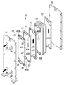
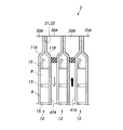
- Exploded perspective view of the power generation module according to the first embodiment Exploded perspective view of a plate unit according to the first embodiment Sectional drawing of the electric power generation module which concerns on 1st Embodiment
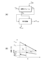
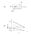
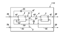
- the (A) block diagram and (B) graph which show the temperature change in the electric power generation system which concerns on 1st Embodiment (A) Block diagram and (B) graph showing temperature change in power generation system according to comparative example
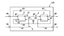
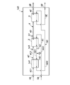
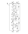
- Block diagram showing a power generation system according to a fourth embodiment Block diagram showing a power generation system according to a fifth embodiment Block diagram showing a power generation system according to a sixth embodiment Block diagram showing a power generation system according to a seventh embodiment
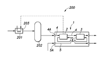
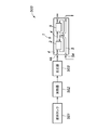
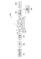
- the block diagram which shows the example which applied the power generation system which concerns on embodiment to an oil refinery plant The block diagram which shows the example which applied the power generation system which concerns on embodiment to the power plant
- the block diagram which shows the example which applied the electric power generation system which concerns on embodiment to the regasification installation of LNG The block diagram which shows the example which applied the power generation system which concerns on embodiment to the reactor
- the power generation system 1 includes a power generation module 2, a heat exchanger 3, and a high temperature fluid passage 4 and a low temperature fluid passage 5 connected to the power generation module 2 and the heat exchanger 3.
- the high-temperature fluid passage 4 includes a high-temperature fluid inlet 4A serving as a high-temperature fluid inlet to the power generation system 1 and a high-temperature fluid outlet 4B serving as a high-temperature fluid discharge port from the power generation system 1. Between the fluid outlet 4B, it is connected to the power generation module 2 and the heat exchanger 3.
- the low-temperature fluid passage 5 includes a low-temperature fluid inlet 5A serving as a low-temperature fluid inlet to the power generation system 1 and a low-temperature fluid outlet 5B serving as a low-temperature fluid discharge port from the power generation system 1. Between the fluid outlet 5B, it is connected to the power generation module 2 and the heat exchanger 3.
- the high-temperature fluid passage 4 includes a passage 4C that connects the high-temperature fluid inlet 4A and the power generation module 2, a passage 4D that connects the power generation module 2 and the heat exchanger 3, the heat exchanger 3 and the high-temperature fluid. And a passage 4E connecting the outlet 4B. That is, the high-temperature fluid passage 4 connects the power generation module 2 and the heat exchanger 3 in series, and the high-temperature fluid flows in the order of the power generation module 2 and the heat exchanger 3.
- the cryogenic fluid passage 5 includes a passage 5C that connects the cryogenic fluid inlet 5A and the power generation module 2, a passage 5D that connects the power generation module 2 and the heat exchanger 3, the heat exchanger 3 and the cryogenic fluid. And a passage 5E connecting the outlet 5B. That is, the low-temperature fluid passage 5 connects the power generation module 2 and the heat exchanger 3 in series, and the low-temperature fluid flows in the order of the power generation module 2 and the heat exchanger 3.
- the low-temperature fluid passage 5 has a bypass passage 5F connected to the passage 5C and the passage 5D so as to bypass the power generation module 2.
- the power generation module 2 includes thermoelectric elements 7A and 7B that convert thermal energy into electrical energy by the Seebeck effect.
- the thermoelectric element 7A is a plurality of p-type semiconductors
- the thermoelectric element 7B is a plurality of n-type semiconductors.
- the thermoelectric elements 7A and 7B may be made of metal.
- thermoelectric elements 7A and 7B are combined to form a subunit 8.
- the subunit 8 has two plates 9A and 9B.
- the plurality of thermoelectric elements 7A and 7B are disposed between the two plates 9A and 9B.
- the plates 9A and 9B are preferably formed from a material having high thermal conductivity.
- the plurality of thermoelectric elements 7A and 7B are arranged in a plane so as to be along the plates 9A and 9B between the two plates 9A and 9B.
- the end portion of the thermoelectric element 7A disposed on the one plate 9A side is connected to the end portion disposed on the one plate 9A side of the adjacent thermoelectric element 7B by the electrode 13, and the other plate 9B side of the thermoelectric element 7A side.
- thermoelectric element 7A and 7B form a series of electric circuits.
- the connection method of each thermoelectric element 7A, 7B can be arbitrarily selected, such as series or parallel.
- the plurality of thermoelectric elements 7A and 7B included in one plate unit 12 are connected to each other in series, and the lead wire 15 is connected to the electrodes 13 that form both ends of the electric circuit. Yes.
- An insulator 16 is provided between the two plates 9A and 9B and the electrode 13, between the electrodes 13, and between the thermoelectric elements 7A and 7B.
- the edges of both plates 9A and 9B are coupled to each other except for the portion where the lead wire 15 is drawn.
- the joining method of both plates 9A and 9B may be, for example, a pressure joining method.
- the plurality of subunits 8 formed as described above are arranged between the two plates 11A and 11B, and constitute the plate unit 12 together with both plates 11A and 11B.
- Each subunit 8 is disposed such that the plates 9A and 9B are in contact with the plates 11A and 11B.
- Each subunit 8 is connected to a respective lead wire 15 to form a series of electric circuits.
- the connection method of each subunit 8 can be arbitrarily selected, such as serial or parallel. In this embodiment, each subunit 8 is connected so as to be in series with each other.
- the edges of both plates 11A and 11B are coupled to each other except for the portion that leads out the lead wire 15 from the subunit 8 arranged at the end of the circuit.
- the joining method of both plates 9A and 9B may be, for example, a pressure joining method.
- thermoelectric elements 7A and 7B are combined into a subunit 8, and this subunit 8 is disposed between the two plates 11A and 11B.
- the plates 9A and 9B are omitted,
- the thermoelectric elements 7A and 7B may be disposed inside the plates 11A and 11B via the insulator 16.
- a first hole 21 and a second hole 22 penetrating both plates 11A and 11B in the thickness direction are formed in the upper edge portion of both plates 11A and 11B joined to each other.
- a third hole 23 and a fourth hole 24 penetrating the plates 11A and 11B in the thickness direction are formed in the lower edge portions of the plates 11A and 11B that are coupled to each other. Since the first to fourth holes 21 to 24 are coupled to the portion where the plates 11A and 11B are coupled to each other, the first to fourth holes 21 to 24 are isolated from the space where the thermoelectric elements 7A and 7B are disposed between the plates 11A and 11B. Yes.
- a gasket is interposed between the plates 11A and 11B, and the space in which the thermoelectric elements 7A and 7B are arranged and the first to fourth holes 21 to 24 may be partitioned in a liquid-tight manner. .
- the power generation module 2 includes a plurality of plate units 12 stacked on the front and rear sides, a front end plate 26 disposed on the front side of the plate unit 12 disposed on the front side, and a rear side of the plate unit 12 disposed on the rear side.
- the rear end plate 27 arranged on the side and between the plate units 12, the plate unit 12 arranged on the foremost side and the front end plate 26, and the plate unit 12 and the rear end plate 27 arranged on the most rear side Gaskets 30A, 30B, 30C disposed between the two.
- a front outer plate 31 is disposed on the front side of the front end plate 26, and a rear outer plate 32 is disposed on the rear side of the rear end plate 27.
- the front outer plate 31 and the rear outer plate 32 are coupled by a plurality of tie rods (not shown) extending in the front-rear direction, and the front end plate 26, the plurality of plate units 12, the rear end plate 27, and the gaskets 30A, 30B, 30C are The front outer plate 31 and the rear outer plate 32 are sandwiched in the front-rear direction.
- the front end plate 26 has a connection hole 35 penetrating in the thickness direction at a portion facing the first to fourth holes 21 to 24.
- the front outer plate 31 has a high temperature fluid inlet hole 36 at a portion facing the first hole 21, a low temperature fluid outlet hole 37 at a portion opposite to the second hole 22, and a high temperature fluid outlet hole 38 at a portion opposite to the third hole 23.
- a cryogenic fluid inlet hole 39 is provided in a portion facing the fourth hole 24.
- the high temperature fluid inlet hole 36, the low temperature fluid outlet hole 37, the high temperature fluid outlet hole 38, and the low temperature fluid inlet hole 39 penetrate the front outer plate 31 in the thickness direction.
- the gaskets 30A, 30B, and 30C include three types of first to third gaskets 30A to 30C.
- the plate units 12 are first, second,... N in ascending order from the front side (n is an odd number in this embodiment).
- the first gasket 30 ⁇ / b> A is interposed between the front surface of the odd-numbered plate unit 12 and the rear surface of the even-numbered plate unit 12 or the rear surface of the front end plate 26.
- the second gasket 30 ⁇ / b> B is interposed between the rear surface of the odd-numbered plate unit 12 and the front surface of the even-numbered plate unit 12 or the front surface of the rear end plate 27.
- the third gasket 30 ⁇ / b> C is interposed between the rear surface of the front outer plate 31 and the front surface of the front end plate 26.
- the first gasket 30A has a low-temperature connection passage 41B that connects the second holes 22 and the fourth holes 24 of the plate units 12 together with the rear surface of the even-numbered plate units 12 and the front surface of the odd-numbered plate units 12. And a high-temperature main passage 42 ⁇ / b> A that connects both the first holes 21 and the third holes 23 of both plate units 12.
- the first gasket 30A includes the rear surface of the front end plate 26 and the front surface of the odd-numbered plate unit 12 as well as the second hole 22 and the connection hole 35 facing the second hole 22, and the fourth hole 24 and the fourth hole.
- connection passage 41B for connecting the connection holes 35 opposed to 24, the first hole 21, the third hole 23, the connection hole 35 opposed to the first hole 21, and the connection hole 35 opposed to the third hole 23, respectively.
- a high-temperature main passage 42A connecting the two.
- the high temperature main passage 42 ⁇ / b> A is formed so as to cover most of the main surface of the plate unit 12.
- the second gasket 30B is a high-temperature connection passage 42B that connects the first holes 21 and the third holes 23 of the plate units 12 together with the rear surface of the odd-numbered plate units 12 and the front surface of the even-numbered plate units 12. And a low-temperature main passage 41 ⁇ / b> A that connects both the second holes 22 and the fourth holes 24 of both plate units 12. Further, the second gasket 30B forms a low-temperature main passage 41A connecting the second hole 22 and the fourth hole 24 together with the rear surface of the odd-numbered plate unit 12 and the front surface of the rear end plate 27, and the first hole 21 and The third hole 23 is closed.
- the low temperature main passage 41 ⁇ / b> A is formed so as to cover most of the main surface of the plate unit 12.
- the high-temperature fluid inlet hole 36 and the high-temperature fluid outlet hole 38 are connected to each other via the high-temperature connection passage 42B, the first hole 21, the high-temperature main passage 42A, and the third hole 23, and the high-temperature fluid passage 4 Part of Similarly, the low temperature fluid inlet hole 39 and the low temperature fluid outlet hole 37 are connected to each other via the low temperature connection passage 41B, the fourth hole 24, the low temperature main passage 41A, and the second hole 22, and Parts. Further, the hot fluid passage 4 is disposed on one of the front and rear surfaces of each plate unit 12, and the cryogenic fluid passage 5 is disposed on the other.
- the high-temperature fluid flowing through the high-temperature fluid passage 4 flows from one side to the bottom of the plate unit 12 (see the white arrow in FIG. 2), and the low-temperature fluid flowing through the low-temperature fluid passage 5 from the other side of the plate unit 12 from below. It flows upward (see the black arrow in FIG. 2), and the high-temperature fluid and the low-temperature fluid become counterflows via the plate unit 12.
- the heat exchanger 3 has a passage through which the high-temperature fluid flows and a passage through which the low-temperature fluid flows, and exchanges heat between the high-temperature fluid and the low-temperature fluid.
- the heat exchanger 3 may be a known heat exchanger 3 such as a plate heat exchanger or a spiral heat exchanger.
- the passage through which the high-temperature fluid flows and the passage through which the low-temperature fluid flow are arranged so that the high-temperature fluid and the low-temperature fluid are opposed to each other.
- the hot fluid inlet hole 36 of the power generation module 2 is connected to the passage 4C
- the hot fluid outlet hole 38 is connected to the passage 4D
- the cold fluid inlet hole 39 is connected to the passage 5C
- the cold fluid outlet hole 37 is connected to the passage 5D. Has been.
- a flow rate adjusting valve 50 is provided in the bypass passage 5F.
- the flow rate adjusting valve 50 adjusts the flow rate of the low temperature fluid flowing through the bypass passage 5F by opening and closing. That is, the flow rate adjustment valve 50 adjusts the flow rate of the low-temperature fluid flowing into the power generation module 2 by opening and closing.
- a high temperature side temperature sensor 51 is provided at the outlet portion of the power generation module 2 in the passage 4D of the high temperature fluid passage 4, and a low temperature side temperature sensor 52 is provided at the outlet portion of the power generation module 2 in the passage 5D of the low temperature fluid passage 5. It has been.
- the low temperature side temperature sensor 52 is provided in a portion of the passage 5D on the upstream side of the portion where the downstream end of the bypass passage 5F is connected.
- the power generation system 1 also has a control device (not shown) that controls the flow rate adjustment valve 50.
- Detection signals from the high temperature side temperature sensor 51 and the low temperature side temperature sensor 52 are input to the control device, and a temperature difference ⁇ T between the high temperature fluid and the low temperature fluid at the outlet of the power generation module 2 is calculated based on these detection signals. .
- the control device sets a target opening degree of the flow rate adjustment valve 50 based on the calculated temperature difference ⁇ T, and controls the flow rate adjustment valve 50 to be opened and closed.
- the control device 53 closes the flow rate adjustment valve 50 when the temperature difference ⁇ T is equal to or larger than a predetermined threshold value, and when the temperature difference ⁇ T is smaller than the threshold value, the flow rate adjustment valve 50 is set so that the opening degree increases as the temperature difference ⁇ T decreases.
- thermoelectric elements 7A and 7B in the plate unit 12 when the high-temperature fluid flows on one side of the plate unit 12 and the low-temperature fluid flows on the other side of the plate unit 12, the end portions on the one side of the thermoelectric elements 7A and 7B in the plate unit 12 are It becomes high temperature with respect to the end portion on the other side surface, and a temperature difference is generated between the thermoelectric elements 7A and 7B. Thereby, an electromotive force is generated in the thermoelectric elements 7A and 7B by the Seebeck effect. The electromotive force generated by the thermoelectric elements 7A and 7B is proportional to the temperature difference generated in the thermoelectric elements 7A and 7B.
- the temperature of the high temperature fluid at the inlet (hot fluid inlet hole 36) of the power generation system 1 is T 1 in , and the outlet of the power generation module 2 (high temperature fluid outlet hole 38, heat exchanger 3).
- the temperature of the hot fluid at the inlet is T1 x
- the temperature of the hot fluid at the outlet of the power generation system 1 is T1 out
- the temperature of the cold fluid at the inlet of the power generation system 1 is T2 in
- the temperature of the cryogenic fluid at the outlet of the power generation module 2 iscold fluid outlet hole 37, the inlet of the heat exchanger 3) T2 x
- the temperature of the cryogenic fluid at the outlet of the power generation system 1 (the outlet of the heat exchanger 3) Is T2 out .
- the temperature difference ⁇ T is set to 30 ° C. or higher, preferably 50 ° C. or higher.
- the temperature difference ⁇ T can be changed by the temperature and flow rate of the hot fluid and the cold fluid.
- the amount of heat lost by the high-temperature fluid in the power generation module 2 is Q g
- the amount of heat lost by the high-temperature fluid in the heat exchanger 3 is Q c
- Heat Q g where the power generation module 2 loses high temperature fluid, the amount of heat Q1 receiving the cryogen by heat conduction, the thermoelectric elements 7A by thermal conduction, joined 7B, the amount of heat Q2 is converted into electricity, the thermoelectric element 7A, the current 7B This is the sum of the Joule heat Q3 generated by flowing and the amount of heat Q4 radiated from the power generation module 2.
- the amount of heat Q5 that contributes to the temperature rise of the low-temperature fluid is a total value of the amount of heat Q1 and Joule heat Q3 received by the low-temperature fluid by heat conduction.
- FIG. 6 shows a power generation system 1 in which the heat exchanger 3 is omitted and only the power generation module 2 is provided as a comparative example of the power generation system 1 according to the present embodiment.
- the temperatures T1 in , T2 in , T1 out of the power generation system 1 according to the present embodiment are the temperatures of the hot fluid and the cold fluid at the inlet of the power generation system 1 according to the comparative example, and the temperatures of the hot fluid and the cold fluid at the outlet of the power generation system 1.
- T2 is the same value as out .
- the temperature difference ⁇ T2 (T1 out ⁇ T2 out ) at the outlet of the power generation module 2 of the high temperature fluid and the low temperature fluid is obtained.
- the temperature difference ⁇ T at the outlet of the power generation module 2 in the power generation system 1 according to the present embodiment is larger than the temperature difference ⁇ T2 at the outlet of the power generation module 2 according to the comparative example, power generation per one thermoelectric element 7A, 7B.
- the amount increases.
- the temperature T2 x of the low temperature fluid at the outlet of the power generation module 2 according to the present embodiment is lower than the temperature T2 out of the low temperature fluid at the outlet of the power generation module 2 according to the comparative example, and the amount of heat Q5 received by the low temperature fluid is small. Therefore, the power generation efficiency of the power generation system 1 according to the present embodiment is improved as compared with the comparative example.
- the power generation system 1 according to the first embodiment includes the heat exchanger 3 on the downstream side of the power generation module 2, an outlet of the power generation system 1 is maintained while maintaining a large temperature difference between the high temperature fluid and the low temperature fluid in the power generation module 2.
- the temperature of the high-temperature fluid in can be lowered to a predetermined value or less. Therefore, in the plant etc., the power generation system 1 according to the present embodiment can be replaced with a place where only the heat exchanger 3 has been conventionally used.
- the electric power generation system 1 which concerns on this embodiment can be formed by adding a thermoelectric module to the upstream of the place where only the heat exchanger 3 was conventionally used.
- the flow rate adjustment valve 50 is controlled based on the temperature difference ⁇ T between the high temperature fluid and the low temperature fluid at the outlet of the power generation module 2, and the flow rate of the low temperature fluid passing through the power generation module 2 is controlled.
- the temperature difference ⁇ T between the high temperature fluid and the low temperature fluid is maintained at a predetermined threshold value or more, and the thermoelectric elements 7A and 7B perform power generation in an efficient state. Thereby, even when the temperature and flow rate of the high-temperature fluid and the low-temperature fluid flowing into the power generation system 1 fluctuate, the power generation module 2 can generate power in an efficient state.
- the power generation systems according to the following second to seventh embodiments are different from the power generation system 1 according to the first embodiment in the configuration of the high-temperature fluid passage and the low-temperature fluid passage.
- the same components as those of the power generation system 1 according to the first embodiment are denoted by the same reference numerals and description thereof is omitted.
- the power generation system 100 according to the second embodiment includes a passage 4C and a passage 4D so that the high-temperature fluid passage 4 bypasses the power generation module 2 as compared with the power generation system 1 according to the first embodiment.
- the difference is that it has a bypass passage 4F connected to.
- the low temperature fluid passage 5 of the power generation system 100 is different in that the bypass passage 5F and the flow rate adjustment valve 50 are omitted.
- a flow rate adjustment valve 55 is provided in the bypass passage 4F.
- the flow rate adjustment valve 55 adjusts the flow rate of the high-temperature fluid flowing through the bypass passage 4F by opening and closing. That is, the flow rate adjustment valve 55 adjusts the flow rate of the high-temperature fluid flowing into the power generation module 2 by opening and closing.
- the flow rate adjusting valve 55 is controlled by the control device based on the temperature difference ⁇ T between the high temperature fluid and the low temperature fluid at the outlet of the power generation module 2.
- the power generation system 100 can adjust the flow rate of the high-temperature fluid supplied to the power generation module 2 by the flow rate adjustment valve 55 even when the temperature and flow rate of the high-temperature fluid and the low-temperature fluid flowing into the power generation system 100 vary. Accordingly, the temperature difference ⁇ T between the high temperature fluid and the low temperature fluid at the outlet of the power generation module 2 is maintained at a predetermined value, and the power generation module 2 can perform power generation in an efficient state.
- the power generation system 110 has a passage 4C and a passage 4D so that the high-temperature fluid passage 4 bypasses the power generation module 2 as compared with the power generation system 1 according to the first embodiment.
- the difference is that it has a bypass passage 4F connected to each other.
- a flow rate adjustment valve 55 is provided in the bypass passage 4F.
- the flow rate adjusting valve 50 is controlled by the control device based on the temperature difference ⁇ T between the high temperature fluid and the low temperature fluid at the outlet of the power generation module 2.
- the power generation system 110 adjusts the flow rates of the high temperature fluid and the low temperature fluid supplied to the power generation module 2 by the flow rate control valves 50 and 55 even when the temperature and flow rate of the high temperature fluid and the low temperature fluid flowing into the power generation system 110 fluctuate. be able to.
- the power generation system 120 has a passage such that the high-temperature fluid passage 4 bypasses the power generation module 2 and the heat exchanger 3 as compared with the power generation system 1 according to the first embodiment.
- the difference is that a bypass passage 4G is connected to 4C and the passage 4E.
- a flow rate adjustment valve 55 is provided in the bypass passage 4G.
- the flow rate adjustment valve 55 adjusts the flow rate of the high-temperature fluid flowing through the bypass passage 4F by opening and closing.
- the flow rate adjusting valve 55 is controlled by the control device based on the temperature difference ⁇ T between the high temperature fluid and the low temperature fluid at the outlet of the power generation module 2.
- the power generation system 130 according to the fifth embodiment is different from the power generation system 1 according to the first embodiment in that each of the high-temperature fluid passage 4 and the low-temperature fluid passage 5 includes the power generation module 2 and the heat exchange.
- the difference is that the devices 3 are connected in parallel.
- the high-temperature fluid passage 4 includes a passage 4H connecting the high-temperature fluid inlet 4A and the power generation module 2, a passage 4J connecting the power generation module 2 and the high-temperature fluid outlet 4B, and a passage connecting the passage 4H and the heat exchanger 3. 4K and a passage 4L connecting the heat exchanger 3 and the passage 4J.
- the passage 4K, the heat exchanger 3, and the passage 4L constitute a series of bypass passages that bypass the power generation module 2.
- a flow rate adjusting valve 131 is provided at a portion on the downstream side (the power generation module 2 side) of the passage 4H where the passage 4K is connected.
- a high temperature side temperature sensor 51 is provided on the upstream side (power generation module 2 side) portion of the passage 4J where the passage 4L is connected.
- the low temperature fluid passage 5 includes a passage 5H connecting the low temperature fluid inlet 5A and the power generation module 2, a passage 5J connecting the power generation module 2 and the low temperature fluid outlet 5B, and a passage connecting the passage 5H and the heat exchanger 3. 5K, and a passage 5L connecting the heat exchanger 3 and the passage 5J.
- the passage 5K, the heat exchanger 3, and the passage 5L constitute a series of bypass passages that bypass the power generation module 2.
- a flow rate adjusting valve 132 is provided in the passage 5K.
- a low temperature side temperature sensor 52 is provided on the upstream side (the power generation module 2 side) portion of the passage 5J where the passage 5L is connected.
- the flow control valves 131 and 132 are controlled by the control device based on the temperature difference ⁇ T between the high temperature fluid and the low temperature fluid at the outlet of the power generation module 2.
- the power generation system 140 according to the sixth embodiment is different from the power generation system 1 according to the first embodiment in that a temperature regulator 141 is provided in the passage 4 ⁇ / b> C of the high-temperature fluid passage 4.
- the temperature controller 141 is a device that adjusts the high-temperature fluid supplied to the power generation system 140 to a temperature suitable for the power generation module 2.
- the temperature controller 141 is a known counter-flow heat exchanger, and the high-temperature fluid supplied to the high-temperature fluid inlet 4A and the low-temperature fluid supplied to the low-temperature fluid inlet 5A are mixed with each other. Heat exchange is performed in an unsuitable manner.
- the temperature controller 141 is connected to the high-temperature fluid inlet 4A by a passage 4C1 that forms an upstream portion of the passage 4C of the high-temperature fluid passage 4, and is connected to the power generation module 2 by a passage 4C2 that forms a downstream portion of the passage 4C.
- the low-temperature fluid passage 5 is connected to the power generation module 2 by a passage 5D1 forming an upstream portion of the passage 5D, and is connected to the heat exchanger 3 by a passage 5D2 forming a downstream portion of the passage 5D.
- the passage 5C and the passage 5D1 are connected to each other by a bypass passage 5D3 that bypasses the power generation module 2.
- a flow rate adjustment valve 142 that changes the flow rate of the low-temperature fluid flowing into the power generation module 2 is provided in the bypass passage 5D3.
- An inlet temperature sensor 143 that detects the temperature of the high-temperature fluid flowing into the power generation module 2 is provided at the inlet portion of the power generation module 2 in the passage 4C2.
- the control device of the power generation system 140 controls the flow rate adjustment valve 142 based on the detection signal of the inlet temperature sensor 143. For example, when the temperature of the high-temperature fluid flowing into the power generation module 2 is equal to or higher than a predetermined value, the control device opens the flow rate control valve 142 and increases the opening degree as the temperature increases.
- thermoelectric elements 7A and 7B of the power generation module 2 may be deformed or damaged when exposed to an excessively high temperature exceeding the operating temperature range. However, in the power generation system 140, the temperature of the high-temperature fluid flowing into the power generation module 2 is high. Since it is controlled by the temperature regulator 141, the thermoelectric elements 7A and 7B are prevented from being damaged. Cooling by the temperature controller 141 is applied when the high-temperature fluid is, for example, steam such as thermal oil or hydrocarbon, high-temperature steam, or the like.
- the power generation system 150 according to the seventh embodiment differs from the power generation system 140 according to the sixth embodiment in the configuration of the temperature regulator 151 and the configuration of the passage 5C.
- the passage 5C includes a passage 5C1 that connects the cryogenic fluid inlet 5A and the power generation module 2, and a passage 5C2 that connects the passage 5C1 and the temperature regulator 151.
- a flow rate adjustment valve 152 that changes the flow rate of the low-temperature fluid flowing into the temperature regulator 141 is provided in the passage 5C2.
- the temperature controller 151 mixes the low temperature fluid supplied by the passage 5C2 with the high temperature fluid flowing from the passage 4C1 to the passage 4C2, and cools the high temperature fluid.
- the control device of the power generation system 150 controls the flow rate adjustment valve 152 based on the detection signal of the inlet temperature sensor 143.
- this embodiment can be applied when a high temperature fluid and a low temperature fluid can be mixed, for example, can be used when a high temperature fluid is steam and a low temperature fluid is water.
- the oil refinery plant 200 includes a heating furnace 201 that heats crude oil, and a distillation apparatus 202 (distillation tower) that distills the crude oil heated in the heating furnace 201.
- the power generation system 1 is provided on the downstream side of the distillation apparatus 202 and is used as a heat exchanger that cools any component (for example, heavy oil, light oil, kerosene, gasoline, etc.) in the crude oil separated in the distillation apparatus 202. .
- the hot fluid inlet 4A of the power generation system 1 is connected to a passage through which an arbitrary component distilled in the distillation apparatus 202 flows, and the cold fluid inlet 5A of the power generation system 1 is connected to a cooling water passage.
- the arbitrary component separated by passing through the distillation apparatus 202 is cooled by passing through the power generation system 1, and the power generation system 1 generates power using a part of the heat amount of the arbitrary component.
- the cold fluid inlet 5A of the power generation system 1 may be connected to a passage through which crude oil before being sent to the heating furnace 201 flows, instead of the cooling water passage.
- the crude oil is heated using the heat amount of any component that has passed through the distillation apparatus 202, so that the energy efficiency in the oil refining plant 200 is improved.
- a heating device 203 that performs heating with electric power is provided on the heating furnace 201 or a passage through which crude oil flows, and the electric power generated by the power generation system 1 is supplied to the heating device 203.
- the heating device 203 may be a heating device using resistance heating, for example. According to this configuration, the energy efficiency in the oil refining plant 200 is improved.
- a heat exchanger or a heater that performs heating by fuel combustion may be applied instead of the heating device 203 that performs heating by electric power.
- a power plant 300 includes a boiler 301 that heats water and generates steam, a steam turbine 302 that is driven by steam generated by the boiler 301, and a generator that is driven by the steam turbine 302. 303 and a condenser 304 that cools and condenses the steam that has passed through the steam turbine 302.
- the power generation system 1 according to the present embodiment is provided between the steam turbine 302 and the condenser 304, and is used as a heat exchanger that cools the steam.
- the hot fluid inlet 4 ⁇ / b> A of the power generation system 1 is connected to a passage through which the steam that has passed through the steam turbine 302 flows, and the cold fluid inlet 5 ⁇ / b> A of the power generation system 1 is connected to a cooling water passage common to the condenser 304. That is, the steam that has passed through the steam turbine 302 is used as a high-temperature fluid, and the cooling water used for the condenser 304 is used as a low-temperature fluid.
- the cooling water may be seawater, for example.
- the steam that has passed through the steam turbine 302 is cooled by passing through the power generation system 1, and the power generation system 1 generates power by using a part of the heat amount of the steam. Since the power generation system generates power by using the heat quantity of steam that is normally discarded in the condenser 304, the energy efficiency of the power plant 300 can be improved.
- the LNG regasification facility 400 includes an LNG tank 401 that stores LNG, and a seawater vaporizer 402 that vaporizes LNG.
- the seawater vaporizer 402 is a device that exchanges heat between seawater and LNG and vaporizes LNG by the heat of seawater.
- the power generation system 1 according to the present embodiment is provided between the LNG tank 401 and the seawater vaporizer 402, and is used as the heat exchanger 3 that raises the temperature of the LNG.
- the high-temperature fluid inlet 4A of the power generation system 1 is connected to a seawater passage common to the seawater vaporizer 402, and the low-temperature fluid inlet 5A of the power generation system 1 is connected to a passage through which LNG from the LNG tank 401 flows. That is, seawater is used as a high temperature fluid and LNG is used as a low temperature fluid. The LNG is heated by passing through the power generation system 1, and the power generation system 1 generates power using a temperature difference between seawater and LNG.
- the reaction facility 500 is a facility that reacts various raw materials to generate products.
- the reaction facility 500 includes a raw material tank 501, a heater 502, and a reactor 503.
- the power generation system 1 can be applied to various chemical industrial plants having a reaction facility 500 such as petrochemical industry, natural gas chemical industry, coal chemical industry, and polymer chemical industry.
- the raw material tank 501 is a tank for storing raw materials.
- the heater 502 heats the raw material supplied from the raw material tank 501 to the reactor 503.
- the heater 502 is, for example, an electric heater or a heat exchanger.
- the reactor 503 is a container that performs an exothermic reaction or an endothermic reaction.
- the power generation system 1 is provided on the downstream side of the reactor 503, and is used as a heat exchanger that cools the product generated in the reactor 503.
- the hot fluid inlet 4A of the power generation system 1 is connected to the outlet of the reactor 503, and the cold fluid inlet 5A of the power generation system 1 is connected to the cooling water passage.
- the product is cooled by passing through the power generation system 1.
- the power generation system 1 generates power using the temperature difference between the product and the cooling water.
- the heater 502 is an electric heater
- the electric power generated by the power generation system 1 is supplied to the heater 502 and used to heat the raw material.
- the dehydrogenation reaction facility 600 is a facility that generates hydrogen and an aromatic compound from a hydrogenated aromatic compound.
- the hydrogenated aromatic compound include benzene, toluene, and naphthalene
- examples of the aromatic compound include cyclohexane, methylcyclohexane, and tetralin.
- the dehydrogenation reaction facility 600 includes a hydrogenated aromatic compound tank 601, a heater 602, a dehydrogenation reactor 603, a gas-liquid separator 604, a hydrogen tank 605, and an aromatic compound tank 606.
- the hydrogenated aromatic compound tank 601 is a tank for storing a hydrogenated aromatic compound as a raw material.
- the heater 602 heats the hydrogenated aromatic compound supplied from the hydrogenated aromatic compound tank 601 to the dehydrogenation reactor 603.
- the heater 602 is, for example, an electric heater or a heat exchanger.
- the dehydrogenation reactor 603 is a reaction vessel filled with a dehydrogenation catalyst that separates a hydrogenated aromatic compound into hydrogen and an aromatic compound.
- the hydrogenated aromatic compound heated by the heater 602 is decomposed by the dehydrogenation reactor 603 and sent to the gas-liquid separator 604 as a mixture of hydrogen and the aromatic compound.
- the gas-liquid separator 604 separates hydrogen that is a gas and aromatic compounds that are a liquid. Hydrogen separated by the gas-liquid separator 604 is stored in the hydrogen tank 605, and the aromatic compound is stored in the aromatic compound tank 606.
- the power generation system 1 is provided between the dehydrogenation reactor 603 and the gas-liquid separation device 604 and is used as a heat exchanger that cools the hydrogen and aromatic compounds generated in the dehydrogenation reactor 603. Is done.
- the hot fluid inlet 4A of the power generation system 1 is connected to the outlet of the dehydrogenation reactor 603, and the cold fluid inlet 5A of the power generation system 1 is connected to the cooling water passage. Hydrogen and aromatic compounds are cooled by passing through the power generation system 1, and gaseous aromatic compounds are condensed.
- the power generation system 1 generates power using a temperature difference between hydrogen and aromatic compounds and cooling water.
- the heater 602 is an electric heater, the electric power generated by the power generation system 1 is supplied to the heater 602 and used to heat the hydrogenated aromatic compound.
- the flow rate adjustment valve (50, 60, etc.) is controlled by the control device based on the temperature difference ⁇ T between the high temperature fluid and the low temperature fluid at the outlet of the power generation module 2.
- the temperature of the low temperature fluid at the outlet of the power generation module 2 may be controlled to be 60 ° C. or less. In this case, the temperature rise of the liquid in the low temperature fluid passage 5 is suppressed, and the generation of algae is suppressed.
Landscapes
- Engineering & Computer Science (AREA)
- Chemical & Material Sciences (AREA)
- Physics & Mathematics (AREA)
- Thermal Sciences (AREA)
- Mechanical Engineering (AREA)
- General Engineering & Computer Science (AREA)
- Oil, Petroleum & Natural Gas (AREA)
- Chemical Kinetics & Catalysis (AREA)
- Organic Chemistry (AREA)
- General Chemical & Material Sciences (AREA)
- Fuel Cell (AREA)
Abstract
【課題】 発電効率が良く、従来の熱交換に置換可能な発電システムを提供する。 【解決手段】 発電システム1であって、熱電素子7A、7Bを備えた発電モジュール2と、熱交換器3と、高温流体入口4A及び高温流体出口4Bを備え、高温流体入口及び高温流体出口の間において発電モジュール及び熱交換器に接続された高温流体通路4と、低温流体入口5A及び低温流体出口5Bを備え、低温流体入口及び低温流体出口の間において発電モジュール及び熱交換器に接続された低温流体通路5とを有し、低温流体通路は、発電モジュールを迂回する低温側バイパス通路5Fと、発電モジュールに流入する低温流体の流量を調節する低温側流量調節弁50とを有し、低温側流量調節弁は、発電モジュールを通過した直後の高温流体及び低温流体の温度差に基づいて開度が制御される。
Description
本発明は、供給される高温流体及び低温流体の温度差を利用して熱電素子により発電すると共に、高温流体及び低温流体の少なくとも一方を所定の温度に調節して排出する発電システムに関する。
ゼーベック効果によって熱エネルギーを電気エネルギーに変換する熱電素子を利用して発電システムを構成したものがある(例えば、特許文献1)。特許文献1では、熱伝導性を有する一対のプレートによって熱電素子を挟み込んでプレート状熱発電ユニットを形成し、プレート状熱発電ユニットを複数積層して、隣り合うプレート状熱発電ユニットの間に高温流体が流れる高温流体通路及び低温流体が流れる低温流体通路を形成している。このような発電システムは、発電プラントに組み込まれ、蒸気タービンを通過した後の水蒸気を高温流体として利用している。この発電システムは、プラントにおける排熱を利用して発電するため、プラント全体のエネルギー効率を高めることができる。
熱電素子は、1つの素子当りの起電力が小さいため、多数の素子を直列接続して使用される。しかしながら、熱電素子の数を増やすと発電システムを通過する間に高温流体及び低温流体間の熱交換量が大きくなり、熱電素子に生じる温度差が小さくなる。熱電素子は、両端に生じる温度差の大きさに応じて起電力が変化するため、温度差が小さい状態で使用すると、1つの素子当りの発電効率が低下し、発電量に対する発電システムのコストが増加する。そのため、発電効率の観点からは、発電システムに含まれる熱電素子の数を減らして高温流体及び低温流体間の熱交換を抑制し、個々の熱電素子に生じる温度差を大きく維持することが好ましい。しかしながら、この場合には発電素子での熱交換量が小さくなるため、排出される高温流体の冷却又は低温流体の加熱、すなわち温度調節を十分に行うことができなくなる。
本発明は、以上の背景を鑑み、熱電素子を備えた発電システムにおいて、熱電素子当たりの発電効率を向上させると共に、排出される高温流体又は低温流体の温度調節を可能にすることを課題とする。
上記課題を解決するために、本発明は発電システム(1)であって、熱電素子(7A、7B)を備えた発電モジュール(2)と、熱交換器(3)と、高温流体入口(4A)及び高温流体出口(4B)を備え、前記高温流体入口及び前記高温流体出口の間において前記発電モジュール及び前記熱交換器に接続された高温流体通路(4)と、低温流体入口(5A)及び低温流体出口(5B)を備え、前記低温流体入口及び前記低温流体出口の間において前記発電モジュール及び前記熱交換器に接続された低温流体通路(5)とを有し、前記低温流体通路は、前記発電モジュールを迂回する低温側バイパス通路(5F)と、前記発電モジュールに流入する低温流体の流量を調節する低温側流量調節弁(50)とを有し、前記低温側流量調節弁は、前記発電モジュールを通過した直後の高温流体及び低温流体の温度差に基づいて開度が制御されることを特徴とする。
この構成によれば、発電モジュールにおける高温流体及び低温流体の温度差を維持するために両者の熱交換量を小さくする場合にも、発電モジュールの下流側に設けられた熱交換器によって高温流体を冷却し、又は低温流体を加熱して、発電システムの外部に排出することができる。すなわち、発電モジュールにおける高温流体及び低温流体の温度差を比較的大きく維持して各熱電素子における発電効率を向上させる場合にも、熱交換器において高温流体又は低温流体の温度を調節して発電システムの外部に排出することができる。そのため、本発明の発電システムは、各種プラントにおいて流体の冷却又は加熱が必要な部分に適用することができ、従来の熱交換システムに置換して使用することができる。また、本発明の発電システムは、従来の熱交換システムの上流側に発電モジュールを追加することによっても構築することができ、既存設備への適用が容易である。また、発電システムでは、発電モジュール及び熱交換器において共通の高温流体及び低温流体を使用するため、装置の構成を簡素にすることができる。また、高温流体及び低温流体は、熱交換器の前に発電モジュールに供給されるため、発電モジュールにおける高温流体及び低温流体の温度差を大きくすることができる。また、高温流体及び低温流体の流量や温度が変化する場合にも、発電モジュールに供給する低温流体の流量を調節して、発電モジュールの出口における高温流体及び低温流体の温度差を所定値以上に維持することができる。
上記の発明において、前記高温流体通路は、前記発電モジュールを迂回する高温側バイパス通路(4F)と、前記発電モジュールに流入する高温流体の流量を調節する高温側流量調節弁(55)とを有し、前記高温側流量調節弁は、前記発電モジュールを通過した直後の高温流体及び低温流体の温度差に基づいて開度が制御されるとよい。
この構成によれば、高温流体及び低温流体の流量や温度が変化する場合にも、発電モジュールに供給する高温流体の流量を調節して、発電モジュールの出口における高温流体及び低温流体の温度差を所定値以上に維持することができる。
また、本発明の他の側面は、発電システム(1)であって、熱電素子(7A、7B)を備えた発電モジュール(2)と、熱交換器(3)と、高温流体入口(4A)及び高温流体出口(4B)を備え、前記高温流体入口及び前記高温流体出口の間において前記発電モジュール及び前記熱交換器に接続された高温流体通路(4)と、低温流体入口(5A)及び低温流体出口(5B)を備え、前記低温流体入口及び前記低温流体出口の間において前記発電モジュール及び前記熱交換器に接続された低温流体通路(5)とを有し、前記高温流体通路は、前記発電モジュールを迂回する高温側バイパス通路(4F)と、前記発電モジュールに流入する高温流体の流量を調節する高温側流量調節弁(55)とを有し、前記高温側流量調節弁は、前記発電モジュールを通過した直後の高温流体及び低温流体の温度差に基づいて開度が制御されることを特徴とする。
上記の発明において、前記高温側バイパス通路(4G)は、前記発電モジュール及び前記熱交換器を迂回してもよい。
この構成によれば、高温流体の温度が低い場合には、高温流体を発電モジュール及び熱交換器に通過させずに外部に排出することができる。
上記の発明において、前記高温流体通路における前記高温流体入口と前記発電モジュールとの間の部分に設けられ、高温流体の温度を調節する温度調節器(141、151)を更に有するとよい。
この構成によれば、発電モジュールに供給する高温流体の温度を調節することができる。これにより、過度に温度が高い高温流体が発電モジュールに供給されることが防止され、熱に伴う熱電素子の損傷が防止される。
上記の発明において、前記温度調節器(151)は、前記低温流体通路から分岐した分岐通路に接続され、前記分岐通路を介して供給される低温流体と、高温流体とを混合することによって高温流体の温度を調節するとよい。
この構成によれば、効率良く高温流体の温度を低下させることができる。例えば、高温流体及び低温流体が混合されても問題がない場合、例えば、高温流体及び低温流体が同種の流体である場合(共に水等の水溶液である場合)に適している。
上記の発明において、前記温度調節器(141)は、前記低温流体通路から分岐した分岐通路に接続され、前記分岐通路を介して供給される低温流体と、高温流体とを互いに混ざり合わない状態で熱交換させることによって高温流体の温度を調節するとよい。
この構成によれば、高温流体と低温流体との混合を避けつつ、高温流体の温度を低下させることができる。例えば、高温流体が炭化水素等の有機溶液であり、低温流体が水等の水溶液である場合に適している。
上記の発明において、前記低温流体出口における低温流体の温度が60℃以下であるとよい。
この構成によれば、低温流体通路内の液温の上昇が抑制され、藻等の発生による低温流体通路の閉塞が抑制される。
上記の発明において、前記発電モジュールは、高温流体及び低温流体が前記熱電素子を挟んで対向流となるように形成されているとよい。
この構成によれば、発電モジュールの各部における高温流体と低温流体との温度差の分布が均質になり、熱電素子による発電の効率が向上する。
以上の構成によれば、発電効率が良く、従来の熱交換システムに置換可能な発電システムを提供することができる。
以下、図面を参照して、本発明に係る発電システムの実施形態について説明する。
(第1実施形態)
図1に示すように、発電システム1は、発電モジュール2と、熱交換器3と、発電モジュール2及び熱交換器3に接続された高温流体通路4及び低温流体通路5とを有する。高温流体通路4は、発電システム1への高温流体の流入口となる高温流体入口4Aと、発電システム1からの高温流体の排出口となる高温流体出口4Bとを備え、高温流体入口4A及び高温流体出口4Bの間において発電モジュール2及び熱交換器3に接続されている。低温流体通路5は、発電システム1への低温流体の流入口となる低温流体入口5Aと、発電システム1からの低温流体の排出口となる低温流体出口5Bとを備え、低温流体入口5A及び低温流体出口5Bの間において発電モジュール2及び熱交換器3に接続されている。
図1に示すように、発電システム1は、発電モジュール2と、熱交換器3と、発電モジュール2及び熱交換器3に接続された高温流体通路4及び低温流体通路5とを有する。高温流体通路4は、発電システム1への高温流体の流入口となる高温流体入口4Aと、発電システム1からの高温流体の排出口となる高温流体出口4Bとを備え、高温流体入口4A及び高温流体出口4Bの間において発電モジュール2及び熱交換器3に接続されている。低温流体通路5は、発電システム1への低温流体の流入口となる低温流体入口5Aと、発電システム1からの低温流体の排出口となる低温流体出口5Bとを備え、低温流体入口5A及び低温流体出口5Bの間において発電モジュール2及び熱交換器3に接続されている。
本実施形態では、高温流体通路4は、高温流体入口4Aと発電モジュール2とを接続する通路4Cと、発電モジュール2と熱交換器3とを接続する通路4Dと、熱交換器3と高温流体出口4Bとを接続する通路4Eとを有する。すなわち、高温流体通路4は、発電モジュール2と熱交換器3とを直列に接続し、高温流体は発電モジュール2、熱交換器3の順に流れる。
本実施形態では、低温流体通路5は、低温流体入口5Aと発電モジュール2とを接続する通路5Cと、発電モジュール2と熱交換器3とを接続する通路5Dと、熱交換器3と低温流体出口5Bとを接続する通路5Eとを有する。すなわち、低温流体通路5は、発電モジュール2と熱交換器3とを直列に接続し、低温流体は発電モジュール2、熱交換器3の順に流れる。また、低温流体通路5は、発電モジュール2を迂回するように通路5Cと通路5Dとに接続されたバイパス通路5Fを有する。
図3及び図4に示すように、発電モジュール2は、ゼーベック効果によって熱エネルギーを電気エネルギーに変換する熱電素子7A、7Bを有している。本実施形態では、熱電素子7Aは複数のp型半導体であり、熱電素子7Bは複数のn型半導体である。他の実施形態では、熱電素子7A、7Bは金属から形成されてもよい。
熱電素子7A、7Bは、複数個が組み合わされてサブユニット8を形成している。サブユニット8は、2枚のプレート9A、9Bを有する。複数の熱電素子7A、7Bは、2枚のプレート9A、9Bの間に配置されている。プレート9A、9Bは、熱伝導率が高い材料から形成されることが好ましい。複数の熱電素子7A、7Bは、2枚のプレート9A、9Bの間において各プレート9A、9Bに沿うように平面状に配置される。熱電素子7Aの一方のプレート9A側に配置される端部は、隣り合う熱電素子7Bの一方のプレート9A側に配置される端部と電極13によって接続され、熱電素子7Aの他方のプレート9B側に配置される端部は、他の隣り合う熱電素子7Bの他方のプレート9B側に配置される端部と電極13によって接続されている。これにより、複数の熱電素子7A、7Bは、一連の電気回路を形成する。各熱電素子7A、7Bの接続方法は、直列や並列等、任意に選択することができる。本実施形態では、1つのプレートユニット12に含まれる複数の熱電素子7A、7Bは、互いに直列となるように接続され、電気回路の両端を形成する電極13には、リード線15が接続されている。
2枚のプレート9A、9Bと電極13との間、各電極13間、各熱電素子7A、7B間には絶縁体16が設けられている。両プレート9A、9Bの縁部は、リード線15を引き出す部分を除いて互いに結合されている。両プレート9A、9Bの結合方法は、例えば加圧接合法であってよい。
以上のように形成された複数のサブユニット8は、2枚のプレート11A、11Bの間に配置され、両プレート11A、11Bと共にプレートユニット12を構成する。各サブユニット8は、各プレート9A、9Bがプレート11A、11Bと接触するように配置される。各サブユニット8は、それぞれのリード線15が接続され、一連の電気回路を形成する。各サブユニット8の接続方法は、直列や並列等、任意に選択することができる。本実施形態では、各サブユニット8は、互いに直列となるように接続されている。両プレート11A、11Bの縁部は、回路の端部に配置されたサブユニット8からのリード線15を引き出す部分を除いて互いに結合されている。両プレート9A、9Bの結合方法は、例えば加圧接合法であってよい。
本実施形態では、熱電素子7A、7Bを組み合わせてサブユニット8とし、このサブユニット8を2枚のプレート11A、11B間に配置したが、他の実施形態では、プレート9A、9Bを省略し、プレート11A、11Bの内側に絶縁体16を介して熱電素子7A、7Bを配置してもよい。
図2に示すように、両プレート11A、11Bの互いに結合された上縁部には、両プレート11A、11Bを厚み方向に貫通する第1孔21及び第2孔22が形成されている。同様に、両プレート11A、11Bの互いに結合された下縁部には、両プレート11A、11Bを厚み方向に貫通する第3孔23及び第4孔24が形成されている。第1~第4孔21~24は、両プレート11A、11Bが互いに結合された部分に結合されているため、両プレート11A、11B間の熱電素子7A、7Bが配置された空間と隔離されている。他の実施形態では、両プレート11A、11B間にガスケットを介装し、熱電素子7A、7Bが配置された空間と、第1~第4孔21~24とを液密に区画してもよい。
発電モジュール2は、前後に積層された複数個のプレートユニット12と、最も前側に配置されたプレートユニット12の前側に配置された前端プレート26と、最も後側に配置されたプレートユニット12の後側に配置された後端プレート27と、各プレートユニット12の間、最も前側に配置されたプレートユニット12と前端プレート26の間、及び最も後側に配置されたプレートユニット12と後端プレート27の間に配置されたガスケット30A、30B、30Cとを有する。前端プレート26の前側には前アウタプレート31が配置され、後端プレート27の後側には後アウタプレート32が配置されている。前アウタプレート31と後アウタプレート32とは前後に延びる複数のタイロッド(図示省略)によって結合され、前端プレート26、複数枚のプレートユニット12、後端プレート27、及び各ガスケット30A、30B、30Cは、前アウタプレート31及び後アウタプレート32によって前後方向から挟持されている。
前端プレート26は、第1~第4孔21~24と対向する部分に、厚み方向に貫通する接続孔35を有する。前アウタプレート31は、第1孔21と対向する部分に高温流体入口孔36、第2孔22と対向する部分に低温流体出口孔37、第3孔23と対向する部分に高温流体出口孔38、第4孔24と対向する部分に低温流体入口孔39を有する。高温流体入口孔36、低温流体出口孔37、高温流体出口孔38、及び低温流体入口孔39は、前アウタプレート31を厚み方向に貫通する。
ガスケット30A、30B、30Cは、第1~第3ガスケット30A~30Cの3種類を含む。各プレートユニット12を前側から昇順に第1、第2、...第nとする(本実施形態ではnは奇数とする)。第1ガスケット30Aは、奇数番のプレートユニット12の前面と、偶数番のプレートユニット12の後面又は前端プレート26の後面との間のそれぞれに介装されている。第2ガスケット30Bは、奇数番のプレートユニット12の後面と、偶数番のプレートユニット12の前面又は後端プレート27の前面との間のそれぞれに介装されている。第3ガスケット30Cは、前アウタプレート31の後面と前端プレート26の前面との間に介装されている。
第1ガスケット30Aは、偶数番のプレートユニット12の後面及び奇数番のプレートユニット12の前面と共に、両プレートユニット12の第2孔22同士、及び第4孔24同士をそれぞれ接続する低温接続通路41Bと、両プレートユニット12の両第1孔21及び両第3孔23の全てを接続する高温主通路42Aとを形成する。同様に、第1ガスケット30Aは、前端プレート26の後面及び奇数番のプレートユニット12の前面と共に、第2孔22と第2孔22に対向する接続孔35、及び第4孔24と第4孔24に対向する接続孔35をそれぞれ接続する低温接続通路41Bと、第1孔21、第3孔23、第1孔21と対向する接続孔35、第3孔23と対向する接続孔35の全てを接続する高温主通路42Aとを形成する。高温主通路42Aは、プレートユニット12の主面の大部分を覆うように形成される。
第2ガスケット30Bは、奇数番のプレートユニット12の後面及び偶数番のプレートユニット12の前面と共に、両プレートユニット12の第1孔21同士、及び第3孔23同士をそれぞれ接続する高温接続通路42Bと、両プレートユニット12の両第2孔22及び両第4孔24の全てを接続する低温主通路41Aとを形成する。また、第2ガスケット30Bは、奇数番のプレートユニット12の後面及び後端プレート27の前面と共に、第2孔22及び第4孔24を接続する低温主通路41Aを形成し、第1孔21及び第3孔23を閉塞する。低温主通路41Aは、プレートユニット12の主面の大部分を覆うように形成される。
第3ガスケット30Cは、前アウタプレート31の後面及び前端プレート26と共に、高温流体入口孔36及び高温流体出口孔38とそれぞれ対向する接続孔35と接続する高温接続通路42Bと、低温流体入口孔39及び低温流体出口孔37とそれぞれ対向する接続孔35と接続する低温接続通路41Bとを形成する。
以上の構成により、高温流体入口孔36と高温流体出口孔38とは、高温接続通路42B、第1孔21、高温主通路42A、及び第3孔23を介して互いに接続され、高温流体通路4の一部を構成する。同様に、低温流体入口孔39と低温流体出口孔37とは、低温接続通路41B、第4孔24、低温主通路41A、及び第2孔22を介して互いに接続され、低温流体通路5の一部を構成する。また、各プレートユニット12の前面及び後面の一方には高温流体通路4が配置され、他方には低温流体通路5が配置される。高温流体通路4を流れる高温流体はプレートユニット12の一側面を上から下に流れ(図2中の白抜き矢印参照)、低温流体通路5を流れる低温流体はプレートユニット12の他側面を下から上に流れ(図2中の黒色矢印参照)、高温流体と低温流体とはプレートユニット12を介して対向流となる。
熱交換器3は、高温流体が流れる通路と、低温流体が流れる通路とを有し、高温流体と低温流体との間で熱交換させる。熱交換器3は、例えばプレート式熱交換器やスパイラル式熱交換器等の公知の熱交換器3であってよい。高温流体が流れる通路と低温流体が流れる通路とは、高温流体及び低温流体が対向流となるように配置されている。
発電モジュール2の高温流体入口孔36は通路4Cに接続され、高温流体出口孔38は通路4Dに接続され、低温流体入口孔39は通路5Cに接続され、低温流体出口孔37は通路5Dに接続されている。
バイパス通路5Fには、流量調節弁50が設けられている。流量調節弁50は、開閉することによって、バイパス通路5Fを流れる低温流体の流量を調節する。すなわち、流量調節弁50は、開閉することによって、発電モジュール2に流入する低温流体の流量を調節する。
高温流体通路4の通路4Dにおける発電モジュール2の出口部分には、高温側温度センサ51が設けられ、低温流体通路5の通路5Dにおける発電モジュール2の出口部分には、低温側温度センサ52が設けられている。なお、低温側温度センサ52は、通路5Dにおいて、バイパス通路5Fの下流端が接続された部分よりも上流側の部分に設けられている。また、発電システム1は、流量調節弁50を制御する制御装置(不図示)を有する。制御装置には、高温側温度センサ51及び低温側温度センサ52の検出信号が入力され、これらの検出信号に基づいて、発電モジュール2の出口における高温流体と低温流体との温度差ΔTを算出する。そして、制御装置は、算出した温度差ΔTに基づいて流量調節弁50の目標開度を設定し、流量調節弁50を開閉制御する。制御装置53は、例えば温度差ΔTが所定の閾値以上の場合に流量調節弁50を閉じ、温度差ΔTが閾値より小さい場合に温度差ΔTが小さくなるほど開度が大きくなるように流量調節弁50を制御する。
発電モジュール2において、高温流体がプレートユニット12の一側面側を流れ、低温流体がプレートユニット12の他側面側を流れると、プレートユニット12内の熱電素子7A、7Bの一側面側の端部が他側面側の端部に対して高温になり、熱電素子7A、7Bに温度差が生じる。これにより、ゼーベック効果によって熱電素子7A、7Bに起電力が発生する。熱電素子7A、7Bが発生する起電力は、熱電素子7A、7Bに生じる温度差に比例する。
図5に示すように、発電システム1における、発電システム1の入口(高温流体入口孔36)における高温流体の温度をT1in、発電モジュール2の出口(高温流体出口孔38、熱交換器3の入口)における高温流体の温度をT1x、発電システム1の出口(熱交換器3の出口)における高温流体の温度をT1out、発電システム1の入口(低温流体入口孔39)における低温流体の温度をT2in、発電モジュール2の出口(低温流体出口孔37、熱交換器3の入口)における低温流体の温度をT2x、発電システム1の出口(熱交換器3の出口)における低温流体の温度をT2outとする。
発電モジュール2の出口における高温流体及び低温流体の温度差ΔT(ΔT=T1x-T2x)は、所定値以上となるように設定されている。温度差ΔTは、30℃以上、好ましくは50℃以上に設定されている。温度差ΔTは、高温流体及び低温流体の温度及び流量によって変化させることができる。
発電システム1では、発電モジュール2において高温流体が失う熱量がQg、熱交換器3において高温流体が失う熱量がQcとなり、システム全体で高温流体が失う熱量がQ0(=Qg+Qc)となる。発電モジュール2において高温流体が失う熱量Qgは、熱伝導によって低温流体が受け取る熱量Q1、熱伝導によって熱電素子7A、7Bに加わり、電気に変換される熱量Q2、熱電素子7A、7Bに電流が流れることによって発生するジュール熱Q3、及び発電モジュール2から放熱される熱量Q4の総和となる。低温流体の昇温に寄与する熱量Q5は、熱伝導によって低温流体が受け取る熱量Q1及びジュール熱Q3の合計値である。低温流体が受け取る熱量Q5(=Q1+Q3)は、低温流体の発電モジュール2における入口温度T2in及び出口温度T2xを測定することによって得ることができる。本実施形態では、発電モジュール2における発電効率η(%)は、低温流体が受け取る熱量Q5を基準として、η=Q2/(Q5+Q2)と定義する。
図6に、本実施形態に係る発電システム1の比較例として、熱交換器3を省略し、発電モジュール2のみとした発電システム1を示す。比較例に係る発電システム1の入口における高温流体及び低温流体の温度、発電システム1の出口における高温流体及び低温流体の温度を本実施形態に係る発電システム1の温度T1in、T2in、T1out、T2outと同じ値とする。この場合、比較例に係る発電システム1では、高温流体及び低温流体の発電モジュール2の出口における温度差ΔT2(T1out-T2out)となる。本実施形態に係る発電システム1での発電モジュール2の出口における温度差ΔTは、比較例に係る発電モジュール2の出口における温度差ΔT2よりも大きくなるため、1つの熱電素子7A、7B当りの発電量が増加する。また、本実施形態に係る発電モジュール2の出口における低温流体の温度T2xは、比較例に係る発電モジュール2の出口における低温流体の温度T2outよりも低くなり、低温流体が受け取る熱量Q5が小さくなるため、本実施形態に係る発電システム1は比較例よりも発電効率が向上する。
第1実施形態に係る発電システム1は、発電モジュール2の下流側に熱交換器3を有するため、発電モジュール2における高温流体と低温流体との温度差を大きく維持しつつ、発電システム1の出口における高温流体の温度を所定値以下まで低下させることができる。そのため、プラント等において、従来、熱交換器3のみが使用されていた場所に、本実施形態に係る発電システム1を置換することができる。また、プラント等において、従来、熱交換器3のみが使用されていた場所の上流側に熱電モジュールを追加することによって、本実施形態に係る発電システム1を形成することができる。
また、発電モジュール2の出口における高温流体と低温流体との温度差ΔTに基づいて流量調節弁50が制御され、発電モジュール2を通過する低温流体の流量が制御されるため、発電モジュール2の出口における高温流体と低温流体との温度差ΔTが所定の閾値以上に維持され、熱電素子7A、7Bが効率の良い状態で発電を行う。これにより、発電システム1に流入する高温流体及び低温流体の温度及び流量が変動する場合にも、発電モジュール2は効率の良い状態で発電を行うことができる。
以下の第2~第7実施形態に係る発電システムは、第1実施形態に係る発電システム1と比較して、高温流体通路及び低温流体通路の構成が異なる。第2~第7実施形態に係る発電システムの構成のうち、第1実施形態に係る発電システム1と同様のものは、同一の符号を付して説明を省略する。
(第2実施形態)
図7に示すように、第2実施形態に係る発電システム100は、第1実施形態に係る発電システム1と比べて、高温流体通路4が発電モジュール2を迂回するように通路4Cと通路4Dとに接続されたバイパス通路4Fを有する点が異なる。また、発電システム100の低温流体通路5において、バイパス通路5F及び流量調節弁50が省略されている点が異なる。
図7に示すように、第2実施形態に係る発電システム100は、第1実施形態に係る発電システム1と比べて、高温流体通路4が発電モジュール2を迂回するように通路4Cと通路4Dとに接続されたバイパス通路4Fを有する点が異なる。また、発電システム100の低温流体通路5において、バイパス通路5F及び流量調節弁50が省略されている点が異なる。
バイパス通路4Fには、流量調節弁55が設けられている。流量調節弁55は、開閉することによって、バイパス通路4Fを流れる高温流体の流量を調節する。すなわち、流量調節弁55は、開閉することによって、発電モジュール2に流入する高温流体の流量を調節する。流量調節弁55は、制御装置によって、発電モジュール2の出口における高温流体と低温流体との温度差ΔTに基づいて制御される。
発電システム100は、発電システム100に流入する高温流体及び低温流体の温度及び流量が変動する場合にも、流量調節弁55によって発電モジュール2に供給する高温流体の流量を調節することができる。これにより、発電モジュール2の出口における高温流体と低温流体との温度差ΔTが所定の値に維持され、発電モジュール2は効率の良い状態で発電を行うことができる。
(第3実施形態)
図8に示すように、第3実施形態に係る発電システム110は、第1実施形態に係る発電システム1と比べて、高温流体通路4が、発電モジュール2を迂回するように通路4Cと通路4Dとに接続されたバイパス通路4Fを有する点が異なる。バイパス通路4Fには流量調節弁55が設けられている。流量調節弁50は、制御装置によって、発電モジュール2の出口における高温流体と低温流体との温度差ΔTに基づいて制御される。
図8に示すように、第3実施形態に係る発電システム110は、第1実施形態に係る発電システム1と比べて、高温流体通路4が、発電モジュール2を迂回するように通路4Cと通路4Dとに接続されたバイパス通路4Fを有する点が異なる。バイパス通路4Fには流量調節弁55が設けられている。流量調節弁50は、制御装置によって、発電モジュール2の出口における高温流体と低温流体との温度差ΔTに基づいて制御される。
発電システム110は、発電システム110に流入する高温流体及び低温流体の温度及び流量が変動する場合にも、流量調節弁50、55によって発電モジュール2に供給する高温流体及び低温流体の流量を調節することができる。
(第4実施形態)
図9に示すように、第4実施形態に係る発電システム120は、第1実施形態に係る発電システム1と比べて、高温流体通路4が発電モジュール2及び熱交換器3を迂回するように通路4Cと通路4Eとに接続されたバイパス通路4Gを有する点が異なる。バイパス通路4Gには、流量調節弁55が設けられている。流量調節弁55は、開閉することによって、バイパス通路4Fを流れる高温流体の流量を調節する。流量調節弁55は、制御装置によって、発電モジュール2の出口における高温流体と低温流体との温度差ΔTに基づいて制御される。
図9に示すように、第4実施形態に係る発電システム120は、第1実施形態に係る発電システム1と比べて、高温流体通路4が発電モジュール2及び熱交換器3を迂回するように通路4Cと通路4Eとに接続されたバイパス通路4Gを有する点が異なる。バイパス通路4Gには、流量調節弁55が設けられている。流量調節弁55は、開閉することによって、バイパス通路4Fを流れる高温流体の流量を調節する。流量調節弁55は、制御装置によって、発電モジュール2の出口における高温流体と低温流体との温度差ΔTに基づいて制御される。
(第5実施形態)
図10に示すように、第5実施形態に係る発電システム130は、第1実施形態に係る発電システム1と比べて、高温流体通路4及び低温流体通路5のそれぞれが、発電モジュール2及び熱交換器3を並列に接続している点が異なる。高温流体通路4は、高温流体入口4Aと発電モジュール2とを接続する通路4Hと、発電モジュール2と高温流体出口4Bとを接続する通路4Jと、通路4Hと熱交換器3とを接続する通路4Kと、熱交換器3と通路4Jとを接続する通路4Lとを有する。通路4K、熱交換器3、及び通路4Lは、発電モジュール2を迂回する一連のバイパス通路を構成する。通路4Hの通路4Kが接続された部分よりも下流側(発電モジュール2側)の部分には、流量調節弁131が設けられている。通路4Jの通路4Lが接続された部分よりも上流側(発電モジュール2側)の部分には、高温側温度センサ51が設けられている。
図10に示すように、第5実施形態に係る発電システム130は、第1実施形態に係る発電システム1と比べて、高温流体通路4及び低温流体通路5のそれぞれが、発電モジュール2及び熱交換器3を並列に接続している点が異なる。高温流体通路4は、高温流体入口4Aと発電モジュール2とを接続する通路4Hと、発電モジュール2と高温流体出口4Bとを接続する通路4Jと、通路4Hと熱交換器3とを接続する通路4Kと、熱交換器3と通路4Jとを接続する通路4Lとを有する。通路4K、熱交換器3、及び通路4Lは、発電モジュール2を迂回する一連のバイパス通路を構成する。通路4Hの通路4Kが接続された部分よりも下流側(発電モジュール2側)の部分には、流量調節弁131が設けられている。通路4Jの通路4Lが接続された部分よりも上流側(発電モジュール2側)の部分には、高温側温度センサ51が設けられている。
低温流体通路5は、低温流体入口5Aと発電モジュール2とを接続する通路5Hと、発電モジュール2と低温流体出口5Bとを接続する通路5Jと、通路5Hと熱交換器3とを接続する通路5Kと、熱交換器3と通路5Jとを接続する通路5Lとを有する。通路5K、熱交換器3、及び通路5Lは、発電モジュール2を迂回する一連のバイパス通路を構成する。通路5Kには、流量調節弁132が設けられている。通路5Jの通路5Lが接続された部分よりも上流側(発電モジュール2側)の部分には、低温側温度センサ52が設けられている。流量調節弁131、132は、制御装置によって、発電モジュール2の出口における高温流体と低温流体との温度差ΔTに基づいて制御される。
(第6実施形態)
図11に示すように、第6実施形態に係る発電システム140は、第1実施形態に係る発電システム1と比べて、高温流体通路4の通路4Cに温度調節器141が設けられている点が異なる。温度調節器141は、発電システム140に供給された高温流体を発電モジュール2に適した温度に調節する装置である。第6実施形態では、温度調節器141は、公知の対向流式の熱交換器であり、高温流体入口4Aに供給された高温流体と、低温流体入口5Aに供給された低温流体とが互いに混ざり合わない態様で熱交換させる。
図11に示すように、第6実施形態に係る発電システム140は、第1実施形態に係る発電システム1と比べて、高温流体通路4の通路4Cに温度調節器141が設けられている点が異なる。温度調節器141は、発電システム140に供給された高温流体を発電モジュール2に適した温度に調節する装置である。第6実施形態では、温度調節器141は、公知の対向流式の熱交換器であり、高温流体入口4Aに供給された高温流体と、低温流体入口5Aに供給された低温流体とが互いに混ざり合わない態様で熱交換させる。
温度調節器141は、高温流体通路4の通路4Cの上流側部分をなす通路4C1によって高温流体入口4Aと接続され、通路4Cの下流側部分をなす通路4C2によって発電モジュール2と接続されている。また、低温流体通路5の通路5Dの上流側部分をなす通路5D1によって発電モジュール2と接続され、通路5Dの下流側部分をなす通路5D2によって熱交換器3と接続されている。通路5Cと通路5D1とは、発電モジュール2を迂回するバイパス通路5D3によって互いに接続されている。バイパス通路5D3には、発電モジュール2に流入する低温流体の流量を変化させる流量調節弁142が設けられている。
通路4C2の発電モジュール2の入口部分には、発電モジュール2に流入する高温流体の温度を検出する入口温度センサ143が設けられている。発電システム140の制御装置は、入口温度センサ143の検出信号に基づいて流量調節弁142を制御する。制御装置は、例えば、発電モジュール2に流入する高温流体の温度が所定値以上の場合に、流量調節弁142を開き、温度が高くなるほど開度を大きくする。
発電モジュール2の熱電素子7A、7Bは、使用温度域を超えた過度な高温に曝された場合に変形や損傷する虞があるが、発電システム140では発電モジュール2に流入する高温流体の温度が温度調節器141によって制御されるため、熱電素子7A、7Bの損傷が防止される。温度調節器141による冷却は、高温流体が例えばサーマルオイルや炭化水素等の蒸気、高温スチーム等である場合に適用される。
(第7実施形態)
図12に示すように、第7実施形態に係る発電システム150は、第6実施形態に係る発電システム140と比べて、温度調節器151の構成、及び通路5Cの構成が異なる。通路5Cは、低温流体入口5Aと発電モジュール2とを接続する通路5C1と、通路5C1と温度調節器151とを接続する通路5C2とを有する。通路5C2には、温度調節器141に流入する低温流体の流量を変化させる流量調節弁152が設けられている。温度調節器151は、通路5C2によって供給される低温流体を、通路4C1から通路4C2に流れる高温流体に混合して、高温流体を冷却する。発電システム150の制御装置は、入口温度センサ143の検出信号に基づいて流量調節弁152を制御する。なお、本実施形態は、高温流体及び低温流体が混合可能な場合に適用することができ、例えば、高温流体がスチーム、低温流体が水である場合等に用いることができる。
図12に示すように、第7実施形態に係る発電システム150は、第6実施形態に係る発電システム140と比べて、温度調節器151の構成、及び通路5Cの構成が異なる。通路5Cは、低温流体入口5Aと発電モジュール2とを接続する通路5C1と、通路5C1と温度調節器151とを接続する通路5C2とを有する。通路5C2には、温度調節器141に流入する低温流体の流量を変化させる流量調節弁152が設けられている。温度調節器151は、通路5C2によって供給される低温流体を、通路4C1から通路4C2に流れる高温流体に混合して、高温流体を冷却する。発電システム150の制御装置は、入口温度センサ143の検出信号に基づいて流量調節弁152を制御する。なお、本実施形態は、高温流体及び低温流体が混合可能な場合に適用することができ、例えば、高温流体がスチーム、低温流体が水である場合等に用いることができる。
次に、以上の第1~第7実施形態の発電システムの各種プラントへの適用例について説明する。以下の例では、第1実施形態に係る発電システム1を適用した例を示すが、第2~第7実施形態に係る発電システム100、110、120、130、140、150も同様に適用することができる。
(石油精製プラントへの適用例)
図13に示すように、石油精製プラント200は、原油を加熱する加熱炉201と、加熱炉201において加熱された原油を蒸留する蒸留装置202(蒸留塔)とを有する。発電システム1は、蒸留装置202の下流側に設けられ、蒸留装置202において分離された原油中の任意の成分(例えば、重油、軽油、灯油、ガソリン等)を冷却する熱交換器として使用される。発電システム1の高温流体入口4Aは、蒸留装置202において蒸留された任意の成分が流れる通路に接続され、発電システム1の低温流体入口5Aは冷却水通路に接続される。蒸留装置202を通過して分離された任意の成分は、発電システム1を通過することによって冷却され、発電システム1は任意の成分が有する熱量の一部を利用して発電を行う。
図13に示すように、石油精製プラント200は、原油を加熱する加熱炉201と、加熱炉201において加熱された原油を蒸留する蒸留装置202(蒸留塔)とを有する。発電システム1は、蒸留装置202の下流側に設けられ、蒸留装置202において分離された原油中の任意の成分(例えば、重油、軽油、灯油、ガソリン等)を冷却する熱交換器として使用される。発電システム1の高温流体入口4Aは、蒸留装置202において蒸留された任意の成分が流れる通路に接続され、発電システム1の低温流体入口5Aは冷却水通路に接続される。蒸留装置202を通過して分離された任意の成分は、発電システム1を通過することによって冷却され、発電システム1は任意の成分が有する熱量の一部を利用して発電を行う。
また、発電システム1の低温流体入口5Aは冷却水通路に代えて、加熱炉201に送られる前の原油が流れる通路に接続されてもよい。この場合、発電システム1において、蒸留装置202を通過した任意の成分が有する熱量を利用して原油が加熱されるため、石油精製プラント200におけるエネルギー効率が向上する。
また、加熱炉201又は原油が流れる通路上に、電力によって加熱を行う加熱装置203を設け、この加熱装置203に発電システム1によって発電された電力を供給する。加熱装置203は、例えば抵抗加熱を利用した加熱装置であってよい。この構成によれば、石油精製プラント200におけるエネルギー効率が向上する。なお、他の実施形態では、電力によって加熱を行う加熱装置203に代えて、熱交換器や燃料燃焼によって加熱を行う加熱器等を適用してもよい。
(発電プラントへの適用例)
図14に示すように、発電プラント300は、水を加熱し、蒸気を生成するボイラー301と、ボイラー301で生成された蒸気によって駆動される蒸気タービン302と、蒸気タービン302によって駆動される発電機303と、蒸気タービン302を通過した蒸気を冷却し、凝縮する復水器304とを有する。本実施形態に係る発電システム1は、蒸気タービン302と復水器304との間に設けられ、蒸気を冷却する熱交換器として使用される。発電システム1の高温流体入口4Aは、蒸気タービン302を通過した蒸気が流れる通路に接続され、発電システム1の低温流体入口5Aは復水器304と共通の冷却水通路に接続される。すなわち、蒸気タービン302を通過した蒸気を高温流体として使用し、復水器304に使用する冷却水を低温流体として使用する。冷却水は、例えば海水であってよい。蒸気タービン302を通過した蒸気は、発電システム1を通過することによって冷却され、発電システム1は蒸気が有する熱量の一部を利用して発電を行う。発電システムは、通常であれば復水器304において捨てられる蒸気の熱量を利用して発電を行うため、発電プラント300のエネルギー効率を向上させることができる。
図14に示すように、発電プラント300は、水を加熱し、蒸気を生成するボイラー301と、ボイラー301で生成された蒸気によって駆動される蒸気タービン302と、蒸気タービン302によって駆動される発電機303と、蒸気タービン302を通過した蒸気を冷却し、凝縮する復水器304とを有する。本実施形態に係る発電システム1は、蒸気タービン302と復水器304との間に設けられ、蒸気を冷却する熱交換器として使用される。発電システム1の高温流体入口4Aは、蒸気タービン302を通過した蒸気が流れる通路に接続され、発電システム1の低温流体入口5Aは復水器304と共通の冷却水通路に接続される。すなわち、蒸気タービン302を通過した蒸気を高温流体として使用し、復水器304に使用する冷却水を低温流体として使用する。冷却水は、例えば海水であってよい。蒸気タービン302を通過した蒸気は、発電システム1を通過することによって冷却され、発電システム1は蒸気が有する熱量の一部を利用して発電を行う。発電システムは、通常であれば復水器304において捨てられる蒸気の熱量を利用して発電を行うため、発電プラント300のエネルギー効率を向上させることができる。
(LNGの再ガス化設備への適用例)
図15に示すように、LNGの再ガス化設備400は、LNGを貯留するLNGタンク401と、LNGを気化する海水気化器402とを有する。海水気化器402は、海水とLNGとを熱交換させ、海水の熱によってLNGを気化させる装置である。本実施形態に係る発電システム1は、LNGタンク401と海水気化器402との間に設けられ、LNGを昇温する熱交換器3として使用される。発電システム1の高温流体入口4Aは海水気化器402と共通の海水通路に接続され、発電システム1の低温流体入口5AはLNGタンク401からのLNGが流れる通路に接続される。すなわち、海水を高温流体として使用し、LNGを低温流体として使用する。LNGは、発電システム1を通過することによって昇温され、発電システム1は海水とLNGとの温度差を利用して発電を行う。
図15に示すように、LNGの再ガス化設備400は、LNGを貯留するLNGタンク401と、LNGを気化する海水気化器402とを有する。海水気化器402は、海水とLNGとを熱交換させ、海水の熱によってLNGを気化させる装置である。本実施形態に係る発電システム1は、LNGタンク401と海水気化器402との間に設けられ、LNGを昇温する熱交換器3として使用される。発電システム1の高温流体入口4Aは海水気化器402と共通の海水通路に接続され、発電システム1の低温流体入口5AはLNGタンク401からのLNGが流れる通路に接続される。すなわち、海水を高温流体として使用し、LNGを低温流体として使用する。LNGは、発電システム1を通過することによって昇温され、発電システム1は海水とLNGとの温度差を利用して発電を行う。
(反応設備への適用例)
図16に示すように、反応設備500は、各種原料を反応させて生成物を生成する設備である。反応設備500は、原料タンク501、加熱器502、反応器503を有する。発電システム1は、反応設備500を有する石油化学工業、天然ガス化学工業、石炭化学工業、高分子化学工業等の各種化学工業プラントに適用することができる。
図16に示すように、反応設備500は、各種原料を反応させて生成物を生成する設備である。反応設備500は、原料タンク501、加熱器502、反応器503を有する。発電システム1は、反応設備500を有する石油化学工業、天然ガス化学工業、石炭化学工業、高分子化学工業等の各種化学工業プラントに適用することができる。
原料タンク501は、原料を貯留するタンクである。加熱器502は、原料タンク501から反応器503に供給される原料を加熱する。加熱器502は、例えば、電気ヒータや熱交換器等である。また、反応器503は、発熱反応又は吸熱反応を行う容器である。
本実施形態に係る発電システム1は、反応器503の下流側に設けられ、反応器503において生成された生成物を冷却する熱交換器として使用される。発電システム1の高温流体入口4Aは反応器503の出口に接続され、発電システム1の低温流体入口5Aは冷却水通路に接続される。生成物は、発電システム1を通過することによって冷却される。発電システム1は、生成物と冷却水との温度差を利用して発電を行う。一例として加熱器502が電気ヒータである場合、発電システム1が発電した電力は、加熱器502に供給され、原料を加熱するために使用される。
(脱水素反応設備への適用例)
図17に示すように、脱水素反応設備600は、水素化芳香族化合物から水素と芳香族化合物とを生成する設備である。水素化芳香族化合物には、例えばベンゼンやトルエン、ナフタレン等が含まれ、芳香族化合物にはシクロヘキサンやメチルシクロヘキサン、テトラリン等が含まれる。脱水素反応設備600は、水素化芳香族化合物タンク601、加熱器602、脱水素反応器603、気液分離装置604、水素タンク605、芳香族化合物タンク606を有する。
図17に示すように、脱水素反応設備600は、水素化芳香族化合物から水素と芳香族化合物とを生成する設備である。水素化芳香族化合物には、例えばベンゼンやトルエン、ナフタレン等が含まれ、芳香族化合物にはシクロヘキサンやメチルシクロヘキサン、テトラリン等が含まれる。脱水素反応設備600は、水素化芳香族化合物タンク601、加熱器602、脱水素反応器603、気液分離装置604、水素タンク605、芳香族化合物タンク606を有する。
水素化芳香族化合物タンク601は、原料である水素化芳香族化合物を貯留するタンクである。加熱器602は、水素化芳香族化合物タンク601から脱水素反応器603に供給される水素化芳香族化合物を加熱する。加熱器602は、例えば、電気ヒータや熱交換器等である。脱水素反応器603は、水素化芳香族化合物を水素と芳香族化合物とに分離する脱水素触媒が充填された反応容器である。加熱器602で加熱された水素化芳香族化合物は、脱水素反応器603で分解され、水素と芳香族化合物との混合物として気液分離装置604に送られる。気液分離装置604は、気体である水素と、液体である芳香族化合物とを分離する。気液分離装置604によって分離された水素は水素タンク605に貯留され、芳香族化合物は芳香族化合物タンク606に貯留される。
本実施形態に係る発電システム1は、脱水素反応器603と気液分離装置604との間に設けられ、脱水素反応器603において生成された水素及び芳香族化合物を冷却する熱交換器として使用される。発電システム1の高温流体入口4Aは脱水素反応器603の出口に接続され、発電システム1の低温流体入口5Aは冷却水通路に接続される。水素及び芳香族化合物は、発電システム1を通過することによって冷却され、気体の芳香族化合物が凝縮される。発電システム1は、水素及び芳香族化合物と冷却水との温度差を利用して発電を行う。一例として加熱器602が電気ヒータである場合、発電システム1が発電した電力は、加熱器602に供給され、水素化芳香族化合物を加熱するために使用される。
以上で具体的実施形態の説明を終えるが、本発明は上記実施形態に限定されることなく幅広く変形実施することができる。例えば、上記の各実施形態では、流量調節弁(50、60等)は、制御装置によって、発電モジュール2の出口における高温流体と低温流体との温度差ΔTに基づいて制御される構成としたが、これに加えて発電モジュール2の出口における低温流体の温度が60℃以下となるように制御されてもよい。この場合、低温流体通路5における液体の温度上昇が抑制され、藻の発生が抑制される。
1,100,110,120,130,140,150...発電システム、2...発電モジュール、3...熱交換器、4...高温流体通路、4A...高温流体入口、4B...高温流体出口、4F,4G...バイパス通路、5...低温流体通路、5A...低温流体入口、5B...低温流体出口、5F...バイパス通路、7A...熱電素子、7B...熱電素子、11...プレート、12...プレートユニット、13...電極、15...リード線、16...絶縁体、30...ガスケット、50,55,142,152...流量調節弁、51...高温側温度センサ、52...低温側温度センサ、141,151...温度調節器、143...入口温度センサ、200...石油精製プラント、201...加熱炉、202...蒸留装置、203...加熱装置、300...発電プラント、301...ボイラー、302...蒸気タービン、303...発電機、304...復水器、400...再ガス化設備、401...LNGタンク、402...海水気化器、600...脱水素反応設備、601...水素化芳香族化合物タンク、501...原料タンク、502...加熱器、503...反応器、602...加熱器、603...脱水素反応器、604...気液分離装置、605...水素タンク、606...芳香族化合物タンク
Claims (9)
- 熱電素子を備えた発電モジュールと、
熱交換器と、
高温流体入口及び高温流体出口を備え、前記高温流体入口及び前記高温流体出口の間において前記発電モジュール及び前記熱交換器に接続された高温流体通路と、
低温流体入口及び低温流体出口を備え、前記低温流体入口及び前記低温流体出口の間において前記発電モジュール及び前記熱交換器に接続された低温流体通路とを有し、
前記低温流体通路は、前記発電モジュールを迂回する低温側バイパス通路と、前記発電モジュールに流入する低温流体の流量を調節する低温側流量調節弁とを有し、
前記低温側流量調節弁は、前記発電モジュールを通過した直後の高温流体及び低温流体の温度差に基づいて開度が制御されることを特徴とする発電システム。 - 前記高温流体通路は、前記発電モジュールを迂回する高温側バイパス通路と、前記発電モジュールに流入する高温流体の流量を調節する高温側流量調節弁とを有し、
前記高温側流量調節弁は、前記発電モジュールを通過した直後の高温流体及び低温流体の温度差に基づいて開度が制御されることを特徴とする請求項1に記載の発電システム。 - 熱電素子を備えた発電モジュールと、
熱交換器と、
高温流体入口及び高温流体出口を備え、前記高温流体入口及び前記高温流体出口の間において前記発電モジュール及び前記熱交換器に接続された高温流体通路と、
低温流体入口及び低温流体出口を備え、前記低温流体入口及び前記低温流体出口の間において前記発電モジュール及び前記熱交換器に接続された低温流体通路とを有し、
前記高温流体通路は、前記発電モジュールを迂回する高温側バイパス通路と、前記発電モジュールに流入する高温流体の流量を調節する高温側流量調節弁とを有し、
前記高温側流量調節弁は、前記発電モジュールを通過した直後の高温流体及び低温流体の温度差に基づいて開度が制御されることを特徴とする発電システム。 - 前記高温側バイパス通路は、前記発電モジュール及び前記熱交換器を迂回することを特徴とする請求項2又は請求項3に記載の発電システム。
- 前記高温流体通路における前記高温流体入口と前記発電モジュールとの間の部分に設けられ、高温流体の温度を調節する温度調節器を更に有することを特徴とする請求項1~請求項4のいずれか1つの項に記載の発電システム。
- 前記温度調節器は、前記低温流体通路から分岐した分岐通路に接続され、前記分岐通路を介して供給される低温流体と、高温流体とを混合することによって高温流体の温度を調節することを特徴とする請求項5に記載の発電システム。
- 前記温度調節器は、前記低温流体通路から分岐した分岐通路に接続され、前記分岐通路を介して供給される低温流体と、高温流体とを互いに混ざり合わない状態で熱交換させることによって高温流体の温度を調節することを特徴とする請求項5に記載の発電システム。
- 前記低温流体出口における低温流体の温度が60℃以下であることを特徴とする請求項1~請求項7のいずれか1つの項に記載の発電システム。
- 前記発電モジュールは、高温流体及び低温流体が前記熱電素子を挟んで対向流となるように形成されていることを特徴とする請求項1~請求項8のいずれか1つの項に記載の発電システム。
Priority Applications (3)
| Application Number | Priority Date | Filing Date | Title |
|---|---|---|---|
| EP16754996.3A EP3264585A4 (en) | 2015-02-25 | 2016-02-23 | Power generation system |
| US15/551,060 US20180033941A1 (en) | 2015-02-25 | 2016-02-23 | Power generation system |
| PH12017501488A PH12017501488A1 (en) | 2015-02-25 | 2017-08-16 | Power generation system |
Applications Claiming Priority (2)
| Application Number | Priority Date | Filing Date | Title |
|---|---|---|---|
| JP2015-035540 | 2015-02-25 | ||
| JP2015035540A JP6685648B2 (ja) | 2015-02-25 | 2015-02-25 | 発電システム |
Publications (1)
| Publication Number | Publication Date |
|---|---|
| WO2016136246A1 true WO2016136246A1 (ja) | 2016-09-01 |
Family
ID=56788215
Family Applications (1)
| Application Number | Title | Priority Date | Filing Date |
|---|---|---|---|
| PCT/JP2016/000962 Ceased WO2016136246A1 (ja) | 2015-02-25 | 2016-02-23 | 発電システム |
Country Status (5)
| Country | Link |
|---|---|
| US (1) | US20180033941A1 (ja) |
| EP (1) | EP3264585A4 (ja) |
| JP (1) | JP6685648B2 (ja) |
| PH (1) | PH12017501488A1 (ja) |
| WO (1) | WO2016136246A1 (ja) |
Cited By (1)
| Publication number | Priority date | Publication date | Assignee | Title |
|---|---|---|---|---|
| US20190189886A1 (en) * | 2017-12-15 | 2019-06-20 | Industrial Technology Research Institute | Power supplying device and heating system |
Families Citing this family (8)
| Publication number | Priority date | Publication date | Assignee | Title |
|---|---|---|---|---|
| SE541066C2 (en) * | 2017-06-16 | 2019-03-26 | Climeon Ab | System and method for eliminating the presence of droplets in a heat exchanger |
| JP6851945B2 (ja) * | 2017-09-19 | 2021-03-31 | 株式会社東芝 | 熱発電システム |
| US10865702B2 (en) * | 2017-12-20 | 2020-12-15 | Marelli Europe S.P.A. | Intercooler provided with a thermoelectric generator for a turbocharged internal combustion heat engine |
| US11859918B2 (en) * | 2020-04-28 | 2024-01-02 | Hamilton Sundstrand Corporation | Crossflow/counterflow subfreezing plate fin heat exchanger |
| SE2100039A1 (en) * | 2021-03-19 | 2022-09-20 | Rutger Simonsson | Plate Heat Exchanger Thermoelectric Generator |
| CN116499298A (zh) * | 2023-05-17 | 2023-07-28 | 铜陵市华兴化工有限公司 | 一种硫酸排渣系统热能回收设备 |
| WO2025101006A1 (ko) * | 2023-11-10 | 2025-05-15 | 엘지이노텍 주식회사 | 열전소자를 포함하는 열교환장치 |
| WO2025101005A1 (ko) * | 2023-11-10 | 2025-05-15 | 엘지이노텍 주식회사 | 열전소자를 포함하는 열교환장치 |
Citations (5)
| Publication number | Priority date | Publication date | Assignee | Title |
|---|---|---|---|---|
| JPH09163773A (ja) * | 1995-12-06 | 1997-06-20 | Mitsubishi Heavy Ind Ltd | 熱電発電装置 |
| JP2002199761A (ja) * | 2000-12-27 | 2002-07-12 | Kawasaki Heavy Ind Ltd | 熱電素子発電装置 |
| JP2003086223A (ja) * | 2001-09-10 | 2003-03-20 | Nippon Steel Corp | 固体電解質型燃料電池と熱電発電装置とのコンバインドシステム |
| JP2005295725A (ja) * | 2004-04-01 | 2005-10-20 | Toyota Motor Corp | 熱電発電装置 |
| WO2015019385A1 (ja) * | 2013-08-07 | 2015-02-12 | パナソニックIpマネジメント株式会社 | 熱発電システム |
Family Cites Families (9)
| Publication number | Priority date | Publication date | Assignee | Title |
|---|---|---|---|---|
| JP2003040601A (ja) * | 2001-07-27 | 2003-02-13 | Kansai Electric Power Co Inc:The | 水素供給方法 |
| JP2005035842A (ja) * | 2003-07-15 | 2005-02-10 | Nippon Oil Corp | 水素製造システム |
| WO2006046590A1 (ja) * | 2004-10-27 | 2006-05-04 | Hino Motors, Ltd. | 熱電発電装置 |
| US9184364B2 (en) * | 2005-03-02 | 2015-11-10 | Rosemount Inc. | Pipeline thermoelectric generator assembly |
| JP2010136507A (ja) * | 2008-12-03 | 2010-06-17 | Ihi Plant Construction Co Ltd | 冷熱用熱発電素子を組み込んだ熱交換器 |
| JP2011192759A (ja) * | 2010-03-12 | 2011-09-29 | Toshiba Corp | 熱電発電システム |
| DE102011103110B4 (de) * | 2011-05-25 | 2014-08-28 | Benteler Automobiltechnik Gmbh | Abgassystem mit Kreislaufwärmerohr |
| JP2013046504A (ja) * | 2011-08-25 | 2013-03-04 | Imasen Electric Ind Co Ltd | 発電システム |
| US8554407B2 (en) * | 2011-09-28 | 2013-10-08 | GM Global Technology Operations LLC | Bypass valve and coolant flow controls for optimum temperatures in waste heat recovery systems |
-
2015
- 2015-02-25 JP JP2015035540A patent/JP6685648B2/ja not_active Expired - Fee Related
-
2016
- 2016-02-23 US US15/551,060 patent/US20180033941A1/en not_active Abandoned
- 2016-02-23 EP EP16754996.3A patent/EP3264585A4/en not_active Withdrawn
- 2016-02-23 WO PCT/JP2016/000962 patent/WO2016136246A1/ja not_active Ceased
-
2017
- 2017-08-16 PH PH12017501488A patent/PH12017501488A1/en unknown
Patent Citations (5)
| Publication number | Priority date | Publication date | Assignee | Title |
|---|---|---|---|---|
| JPH09163773A (ja) * | 1995-12-06 | 1997-06-20 | Mitsubishi Heavy Ind Ltd | 熱電発電装置 |
| JP2002199761A (ja) * | 2000-12-27 | 2002-07-12 | Kawasaki Heavy Ind Ltd | 熱電素子発電装置 |
| JP2003086223A (ja) * | 2001-09-10 | 2003-03-20 | Nippon Steel Corp | 固体電解質型燃料電池と熱電発電装置とのコンバインドシステム |
| JP2005295725A (ja) * | 2004-04-01 | 2005-10-20 | Toyota Motor Corp | 熱電発電装置 |
| WO2015019385A1 (ja) * | 2013-08-07 | 2015-02-12 | パナソニックIpマネジメント株式会社 | 熱発電システム |
Non-Patent Citations (1)
| Title |
|---|
| See also references of EP3264585A4 * |
Cited By (1)
| Publication number | Priority date | Publication date | Assignee | Title |
|---|---|---|---|---|
| US20190189886A1 (en) * | 2017-12-15 | 2019-06-20 | Industrial Technology Research Institute | Power supplying device and heating system |
Also Published As
| Publication number | Publication date |
|---|---|
| US20180033941A1 (en) | 2018-02-01 |
| PH12017501488A1 (en) | 2018-01-15 |
| JP2016158424A (ja) | 2016-09-01 |
| EP3264585A4 (en) | 2018-12-26 |
| JP6685648B2 (ja) | 2020-04-22 |
| EP3264585A1 (en) | 2018-01-03 |
Similar Documents
| Publication | Publication Date | Title |
|---|---|---|
| JP6685648B2 (ja) | 発電システム | |
| JP6606248B2 (ja) | 3次元チャネルガス熱交換器 | |
| Islam et al. | The potential of using nanofluids in PEM fuel cell cooling systems: A review | |
| US20130213449A1 (en) | Thermoelectric plate and frame exchanger | |
| CN103210575B (zh) | 通过使用来自冷凝器的热量热循环可电极化材料来发电的方法和设备 | |
| US20100243016A1 (en) | Thermoelectric power generating device and power generating system using said thermoelectric power generating device | |
| CN103916051B (zh) | 用于车辆的堆叠型热电发电机 | |
| JP2014159945A (ja) | 熱交換器 | |
| CN111902672B (zh) | 中间介质式气化器 | |
| JP2011181767A (ja) | 熱電発電装置および熱電発電システム | |
| EP3559582A1 (en) | Heat exchanger and heat exchange method using same | |
| WO2015004486A1 (en) | Thermoelectric generator | |
| AU2015324942A1 (en) | Thermoelectric generating unit and methods of making and using same | |
| EP3534527A1 (en) | Thermoelectric generation system | |
| JP2010135643A (ja) | 熱電変換装置、熱電発電システム、および熱電発電方法 | |
| JP2005072080A (ja) | Lng気化熱利用発電装置 | |
| JP2013092280A (ja) | Voc処理装置用熱利用装置 | |
| Srinivasan et al. | Enhancement of energy efficiency at an Indian milk processing plant using exergy analysis | |
| JP2011519006A (ja) | 主交換ラインおよびこのような交換ラインを組込んだ深冷蒸留空気分離ユニット | |
| JP3571390B2 (ja) | Lng冷熱利用発電システム | |
| KR20240058904A (ko) | 액체 수소 기화 장치 및 수소를 생성하는 생성 방법 | |
| JP2012227982A (ja) | 熱電変換装置 | |
| Nandakishora et al. | Rating and performance of plate fin heat exchanger used for cryogenic separation of CO2 | |
| FR3075480B1 (fr) | Systeme de generation d'electricite incluant deux piles a combustible a temperatures de fonctionnement differentes | |
| JP6139348B2 (ja) | 熱電発電装置 |
Legal Events
| Date | Code | Title | Description |
|---|---|---|---|
| 121 | Ep: the epo has been informed by wipo that ep was designated in this application |
Ref document number: 16754996 Country of ref document: EP Kind code of ref document: A1 |
|
| WWE | Wipo information: entry into national phase |
Ref document number: 12017501488 Country of ref document: PH |
|
| NENP | Non-entry into the national phase |
Ref country code: DE |
|
| REEP | Request for entry into the european phase |
Ref document number: 2016754996 Country of ref document: EP |