WO2016136311A1 - 情報処理装置、情報処理方法及びプログラム - Google Patents
情報処理装置、情報処理方法及びプログラム Download PDFInfo
- Publication number
- WO2016136311A1 WO2016136311A1 PCT/JP2016/050837 JP2016050837W WO2016136311A1 WO 2016136311 A1 WO2016136311 A1 WO 2016136311A1 JP 2016050837 W JP2016050837 W JP 2016050837W WO 2016136311 A1 WO2016136311 A1 WO 2016136311A1
- Authority
- WO
- WIPO (PCT)
- Prior art keywords
- information processing
- processing apparatus
- virtual
- information
- generation unit
- Prior art date
- Legal status (The legal status is an assumption and is not a legal conclusion. Google has not performed a legal analysis and makes no representation as to the accuracy of the status listed.)
- Ceased
Links
Images


Classifications
-
- G—PHYSICS
- G06—COMPUTING OR CALCULATING; COUNTING
- G06T—IMAGE DATA PROCESSING OR GENERATION, IN GENERAL
- G06T17/00—Three-dimensional [3D] modelling for computer graphics
- G06T17/20—Finite element generation, e.g. wire-frame surface description, tesselation
-
- G—PHYSICS
- G06—COMPUTING OR CALCULATING; COUNTING
- G06F—ELECTRIC DIGITAL DATA PROCESSING
- G06F3/00—Input arrangements for transferring data to be processed into a form capable of being handled by the computer; Output arrangements for transferring data from processing unit to output unit, e.g. interface arrangements
- G06F3/01—Input arrangements or combined input and output arrangements for interaction between user and computer
- G06F3/03—Arrangements for converting the position or the displacement of a member into a coded form
- G06F3/0304—Detection arrangements using opto-electronic means
- G06F3/0325—Detection arrangements using opto-electronic means using a plurality of light emitters or reflectors or a plurality of detectors forming a reference frame from which to derive the orientation of the object, e.g. by triangulation or on the basis of reference deformation in the picked up image
-
- G—PHYSICS
- G06—COMPUTING OR CALCULATING; COUNTING
- G06F—ELECTRIC DIGITAL DATA PROCESSING
- G06F3/00—Input arrangements for transferring data to be processed into a form capable of being handled by the computer; Output arrangements for transferring data from processing unit to output unit, e.g. interface arrangements
- G06F3/01—Input arrangements or combined input and output arrangements for interaction between user and computer
- G06F3/03—Arrangements for converting the position or the displacement of a member into a coded form
- G06F3/033—Pointing devices displaced or positioned by the user, e.g. mice, trackballs, pens or joysticks; Accessories therefor
- G06F3/0346—Pointing devices displaced or positioned by the user, e.g. mice, trackballs, pens or joysticks; Accessories therefor with detection of the device orientation or free movement in a three-dimensional [3D] space, e.g. 3D mice, 6-DOF [six degrees of freedom] pointers using gyroscopes, accelerometers or tilt-sensors
-
- G—PHYSICS
- G06—COMPUTING OR CALCULATING; COUNTING
- G06F—ELECTRIC DIGITAL DATA PROCESSING
- G06F3/00—Input arrangements for transferring data to be processed into a form capable of being handled by the computer; Output arrangements for transferring data from processing unit to output unit, e.g. interface arrangements
- G06F3/01—Input arrangements or combined input and output arrangements for interaction between user and computer
- G06F3/03—Arrangements for converting the position or the displacement of a member into a coded form
- G06F3/041—Digitisers, e.g. for touch screens or touch pads, characterised by the transducing means
- G06F3/042—Digitisers, e.g. for touch screens or touch pads, characterised by the transducing means by opto-electronic means
- G06F3/0425—Digitisers, e.g. for touch screens or touch pads, characterised by the transducing means by opto-electronic means using a single imaging device like a video camera for tracking the absolute position of a single or a plurality of objects with respect to an imaged reference surface, e.g. video camera imaging a display or a projection screen, a table or a wall surface, on which a computer generated image is displayed or projected
-
- G—PHYSICS
- G06—COMPUTING OR CALCULATING; COUNTING
- G06F—ELECTRIC DIGITAL DATA PROCESSING
- G06F3/00—Input arrangements for transferring data to be processed into a form capable of being handled by the computer; Output arrangements for transferring data from processing unit to output unit, e.g. interface arrangements
- G06F3/01—Input arrangements or combined input and output arrangements for interaction between user and computer
- G06F3/048—Interaction techniques based on graphical user interfaces [GUI]
- G06F3/0481—Interaction techniques based on graphical user interfaces [GUI] based on specific properties of the displayed interaction object or a metaphor-based environment, e.g. interaction with desktop elements like windows or icons, or assisted by a cursor's changing behaviour or appearance
-
- G—PHYSICS
- G06—COMPUTING OR CALCULATING; COUNTING
- G06F—ELECTRIC DIGITAL DATA PROCESSING
- G06F3/00—Input arrangements for transferring data to be processed into a form capable of being handled by the computer; Output arrangements for transferring data from processing unit to output unit, e.g. interface arrangements
- G06F3/01—Input arrangements or combined input and output arrangements for interaction between user and computer
- G06F3/048—Interaction techniques based on graphical user interfaces [GUI]
- G06F3/0484—Interaction techniques based on graphical user interfaces [GUI] for the control of specific functions or operations, e.g. selecting or manipulating an object, an image or a displayed text element, setting a parameter value or selecting a range
- G06F3/04845—Interaction techniques based on graphical user interfaces [GUI] for the control of specific functions or operations, e.g. selecting or manipulating an object, an image or a displayed text element, setting a parameter value or selecting a range for image manipulation, e.g. dragging, rotation, expansion or change of colour
-
- G—PHYSICS
- G06—COMPUTING OR CALCULATING; COUNTING
- G06F—ELECTRIC DIGITAL DATA PROCESSING
- G06F3/00—Input arrangements for transferring data to be processed into a form capable of being handled by the computer; Output arrangements for transferring data from processing unit to output unit, e.g. interface arrangements
- G06F3/01—Input arrangements or combined input and output arrangements for interaction between user and computer
- G06F3/048—Interaction techniques based on graphical user interfaces [GUI]
- G06F3/0487—Interaction techniques based on graphical user interfaces [GUI] using specific features provided by the input device, e.g. functions controlled by the rotation of a mouse with dual sensing arrangements, or of the nature of the input device, e.g. tap gestures based on pressure sensed by a digitiser
-
- G—PHYSICS
- G06—COMPUTING OR CALCULATING; COUNTING
- G06T—IMAGE DATA PROCESSING OR GENERATION, IN GENERAL
- G06T19/00—Manipulating three-dimensional [3D] models or images for computer graphics
- G06T19/20—Editing of three-dimensional [3D] images, e.g. changing shapes or colours, aligning objects or positioning parts
-
- G—PHYSICS
- G06—COMPUTING OR CALCULATING; COUNTING
- G06T—IMAGE DATA PROCESSING OR GENERATION, IN GENERAL
- G06T2219/00—Indexing scheme for manipulating 3D models or images for computer graphics
- G06T2219/20—Indexing scheme for editing of 3D models
- G06T2219/2004—Aligning objects, relative positioning of parts
-
- G—PHYSICS
- G06—COMPUTING OR CALCULATING; COUNTING
- G06T—IMAGE DATA PROCESSING OR GENERATION, IN GENERAL
- G06T2219/00—Indexing scheme for manipulating 3D models or images for computer graphics
- G06T2219/20—Indexing scheme for editing of 3D models
- G06T2219/2012—Colour editing, changing, or manipulating; Use of colour codes
Definitions
- the present disclosure relates to an information processing apparatus, an information processing method, and a program.
- 3D computer graphics has been used in various fields.
- the user can generate 3DCG in the virtual space or view the virtual space from an arbitrary viewpoint.
- the user is required to perform complicated operations such as specifying the position in the virtual space with three coordinates of the X coordinate, the Y coordinate, and the Z coordinate, and specifying various parameters. For this reason, techniques for improving the operating environment of 3DCG applications have been developed.
- Patent Document 1 discloses a technique for determining the position of a viewpoint defined in a virtual space according to the attitude of a device in a real space.
- the viewpoint in the virtual space can be operated by the posture of the device in the real space.
- a virtual object exists in addition to an action point that is a user's operation target such as a viewpoint. It is desirable that this virtual object can be operated by an intuitive operation in the real space. Therefore, the present disclosure proposes a new and improved information processing apparatus, information processing method, and program capable of providing a more intuitive 3DCG application operation environment.
- the first operation information detected for the first real object corresponding to the virtual object in the virtual space and the second real object corresponding to the virtual tool in the virtual space are detected.
- An information processing apparatus includes a generation unit that generates display control information for displaying the virtual space based on second operation information.
- the first operation information detected for the first real object corresponding to the virtual object in the virtual space and the second real object corresponding to the virtual tool in the virtual space are detected.
- An information processing method executed by a processor is provided that includes generating display control information for displaying the virtual space based on the second operation information.
- the computer causes the first operation information detected for the first real object corresponding to the virtual object in the virtual space and the second real information corresponding to the virtual tool in the virtual space.
- a program for functioning as a generation unit that generates display control information for displaying the virtual space based on second operation information detected for an object is provided.
- elements having substantially the same functional configuration may be distinguished by adding different alphabets after the same reference numerals.
- a plurality of elements having substantially the same functional configuration are distinguished as information processing apparatuses 100A, 100B, and 100C as necessary.
- only the same reference numerals are given.
- the information processing apparatuses 100A, 100B, and 100C they are simply referred to as the information processing apparatus 100.
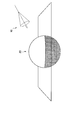
- FIGS. 1 and 2 are diagrams for explaining an operation environment in a 3DCG application.
- FIG. 1 shows an example of a virtual space of a 3DCG application.
- the user can give various actions to the virtual space by operating the manipulator 10.
- the manipulator 10 has directionality and can act in the direction in which the manipulator 10 faces. Further, the manipulator 10 can function as a virtual tool.
- the manipulator 10 is a light manipulator that functions as a light, and can irradiate a spotlight from the position of the manipulator 10 toward the virtual object 20.
- the user can give various actions such as movement, deformation, or coloring of the virtual object 20 to the virtual space using various types of manipulators such as a manipulator for movement, deformation, or coloring in addition to the manipulator for light. it can.
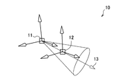
- the direction 13 of the manipulator 10 is specified by the origin 11 and the gazing point 12. Therefore, the user has specified the coordinates (X coordinate, Y coordinate, and Z coordinate) of the origin 11 and the point of gaze 12 in order to operate the direction 13 of the manipulator 10.
- the user has performed an operation such as moving the virtual object 20 via a moving manipulator, for example.
- operating the virtual object 20 can also be complicated as with the manipulator 10.
- the manipulator 10 and the virtual object 20 are operated separately and simultaneously such that the manipulator 10 functions as a virtual tool such as a light, and the position and orientation of the virtual object 20 are manipulated while manipulating the position and orientation of the light. It was difficult to do.
- the information processing system according to an embodiment of the present disclosure has been created with the above circumstances taken into consideration.
- the information processing system according to the present embodiment can provide a more intuitive 3DCG application operating environment.
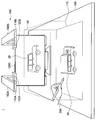
- FIG. 3 is a diagram illustrating an example of an external configuration of the information processing system 1 according to the present embodiment. As shown in FIG. 3, the information processing apparatus 100 and the operation pen 200 are included.
- the information processing apparatus 100 has one or more movable arms 160.
- the arms 160A and 160B have sensor units 110A and 110B and display units 120A and 120B, respectively.
- the sensor units 110A and 110B include an image sensor that can capture an image (still image / moving image) and a depth sensor that can acquire depth information (distance in the depth direction), and shows the state of the recognition range 190 on the table 180. It can be detected.
- the image sensor may be realized by an RGB camera, for example, and the depth sensor may be realized by an IR (infrared) stereo camera, for example.
- Display units 120A and 120B are realized by, for example, a projector, and project an image on projection surface 170.
- the projected image is, for example, an operation screen of a 3DCG application.
- the projection surface 170 may have a function as a touch panel, and may detect contact with the operation pen 200.
- Projectors 120 ⁇ / b> A and 120 ⁇ / b> B project the same image onto projection plane 170 with their projection positions aligned with each other. Since a plurality of projection lights are irradiated from different positions, even if there is an obstacle such as a user's hand existing on the projection plane 170, it can be generated by an obstacle such as a user's hand existing on the projection plane 170. Since the shadow becomes thin, the visibility of the image on the projection surface at the position of the shadow can be improved.
- the information processing apparatus 100 may further include a display unit 120C.
- the display unit 120C is realized by a display, for example, and displays an image.
- the displayed image is, for example, an operation screen of a 3DCG application.
- the projectors 120A and 120B and the display 120C may display different images or may display the same image.
- the projectors 120 ⁇ / b> A and 120 ⁇ / b> B and the display 120 ⁇ / b> C display a state where the virtual object 20 of the car is viewed from different angles.
- the operation pen 200 is a device operated by a user.
- the operation pen 200 may be held by the user's hand as shown in FIG. 3, may be placed on the projection surface 170, or may be supported by an arbitrary support device such as a tripod.
- an example of the external configuration of the operation pen 200 will be described in detail with reference to FIG.
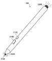
- FIG. 4 is a diagram illustrating an example of an external configuration of the operation pen 200 according to the present embodiment. As shown in FIG. 4, the operation pen 200 is provided with a plurality of input units 210 and a plurality of light emitting units 220.
- the input unit 210 has a function of accepting user input.
- the input unit 210 is a button.
- the button 210A corresponds to a left click of the mouse.
- the button 210B corresponds to a right click of the mouse.
- the button 210C is a general purpose button to which an arbitrary function is assigned.
- the input unit 210 may be realized by a touch sensor, a toggle, a slider, or the like.
- the light emitting unit 220 has a function of emitting light.
- the light emitting unit 220 is realized by an LED (light emitting diode) or an IR LED.
- the sensor unit 110 can easily detect the posture of the operation pen 200 as compared to the case where no light is emitted.
- a passive marker such as a barcode may be attached to the operation pen 200 instead of or together with the light emitting unit 220.
- the operation pen 200 may include an inertial sensor such as an acceleration sensor and a gyro sensor, a speed sensor, a vibration sensor, a biological sensor, and the like. Further, the operation pen 200 may have a communication unit capable of wireless communication using an arbitrary communication method such as a wireless local area network (LAN), Wi-Fi (registered trademark), or Bluetooth (registered trademark). Various types of data may be transmitted / received to / from the information processing apparatus 100.
- LAN wireless local area network
- Wi-Fi registered trademark
- Bluetooth registered trademark
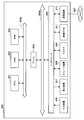
- FIG. 5 is a block diagram illustrating an example of a logical configuration of the information processing apparatus 100 according to the present embodiment.
- the information processing apparatus 100 includes a sensor unit 110, a display unit 120, a communication unit 130, a storage unit 140, and a control unit 150.
- the sensor unit 110 has a function of detecting the state of the recognition range 190.
- the sensor unit 110 includes, for example, an image sensor and a depth sensor, and detects image information and depth information related to a real object such as the operation pen 200 existing in the recognition range 190.
- the sensor unit 110 outputs the detected information to the control unit 150.
- the display unit 120 has a function of displaying information. As described above, the display unit 120 can be realized by a projector and a display. The display unit 120 outputs an operation screen of the 3DCG application based on the control by the control unit 150.
- the communication unit 130 is a communication module for transmitting / receiving data to / from an external device by wire / wireless.
- the communication unit 130 communicates with the operation pen 200 using an arbitrary communication method such as wireless LAN, Wi-Fi, or Bluetooth.
- the communication unit 130 can receive information input to the input unit 210 and information detected by an inertial sensor built in the operation pen 200.
- the communication unit 130 outputs the received information to the control unit 150.
- the storage unit 140 is a part that records and reproduces data with respect to a predetermined recording medium.
- the storage unit 140 stores information indicating the operation content based on a storage instruction from the user.
- the control unit 150 functions as an arithmetic processing unit and a control unit, and controls the overall operation in the information processing apparatus 100 according to various programs. As illustrated in FIG. 5, the control unit 150 functions as an acquisition unit 151, a storage control unit 153, a generation unit 155, and a display control unit 157.
- the acquisition unit 151 has a function of acquiring operation information indicating the content of an operation performed by the user.
- the storage control unit 153 has a function of storing information in the storage unit 140 and reading out information stored in the storage unit 140.
- the generation unit 155 has a function of generating display control information that defines the contents to be displayed on the display unit 120.
- the display control information may be an image display signal such as an RGB signal or an HDMI (registered trademark) signal, or may be an HTML file or the like.
- the display control unit 157 has a function of controlling the display unit 120 to perform display based on the display control information generated by the generation unit 155.
- the information processing apparatus 100 acquires coordinates from the 3DCG application and performs various types of information processing based on the acquired coordinates.
- Communication such as input and output of coordinates performed between the control unit 150 and the 3DCG application may be performed by an API or a plug-in of the 3DCG application.
- FIG. 6 is a diagram for explaining an overview of the information processing apparatus 100 according to the present embodiment.
- the user operates the operation pen 200 within the recognition range 190.
- the display 120C displays a state where the virtual object 20 of the car is viewed from the rear side, and the state of the virtual object 20 of the vehicle viewed from above is displayed on the projection plane 170.
- the position and posture of the operation pen 200 in the recognition range 190 are reflected in the position and posture of the manipulator 10.
- the information processing apparatus 100 (for example, the acquisition unit 151) has a function of acquiring operation information indicating the content of an operation by the user.
- the operation information in the present embodiment includes information indicating the position and orientation of the real object operated by the user such as the operation pen 200 in the real space.
- the acquisition unit 151 recognizes the image of the operation pen 200 from the image information detected by the sensor unit 110, or recognizes the height of the operation pen 200 from the depth information detected by the sensor unit 110.
- the position and posture of the operation pen 200 may be acquired.
- the acquisition unit 151 may acquire the position and orientation of the operation pen 200 by specifying the coordinates of both ends (light emitting units 220A and 220B) of the operation pen 200.
- the acquisition unit 151 may acquire the attitude of the operation pen 200 from the information received by the communication unit 130 and detected by a sensor built in the operation pen 200. For example, the acquisition unit 151 acquires the posture of the operation pen 200 from the detection result of gravity acceleration.
- the acquisition unit 151 receives information input to the input unit 210 of the operation pen 200 and information such as acceleration and speed detected by a sensor built in the operation pen 200 received by the communication unit 130. Can be acquired as operation information.
- the operation information is information indicating the user's finger and posture.
- the acquisition unit 151 can acquire the operation information by specifying the base of the user's finger and the coordinates of the tip in the same manner as the both ends of the operation pen 200.
- the information processing apparatus 100 (for example, the generation unit 155) has a function of converting coordinates in the real space into coordinates in the virtual space.
- the generation unit 155 converts the coordinates of both ends of the operation pen 200 in the real space into the coordinates of the origin 11 and the gazing point 12 of the manipulator 10 in the virtual space. More specifically, the generation unit 155 reflects the position and posture of the operation pen 200 (the coordinates of the light emitting units 220A and 220B) in the position and posture of the manipulator 10 (the coordinates of the origin 11 and the gazing point 12). For example, the generation unit 155 converts the coordinates of the light emitting unit 220B of the operation pen 200 in the real space into the coordinates of the origin 11 of the manipulator 10, and converts the coordinates of the light emitting unit 220A into the coordinates of the gazing point 12 of the manipulator 10. . As a result, the user can operate as if he / she moves the manipulator 10 in the virtual space by holding the operation pen 200 in his / her hand and moving it in the recognition range 190.
- the coordinates of the conversion destination are global coordinates unless otherwise specified.
- the global coordinates are coordinates indicating an absolute position in the virtual space.
- the local coordinates are coordinates indicating a relative position based on an arbitrary position (simple coordinates or virtual object) in the virtual space.
- the generation unit 155 may perform coordinate conversion in accordance with enlargement or reduction of the display of the virtual space. For example, the generation unit 155 converts the movement distance of the operation pen 200 within the recognition range 190 into a movement distance in the virtual space that matches the scale of the virtual space. For example, when the virtual space is enlarged and a part of the virtual object 20 is displayed, the movable range of the manipulator 10 is limited to the part, and the virtual space is reduced and the whole virtual object 20 is displayed. In this case, the range of motion of the manipulator 10 extends over the entire range.
- the information processing apparatus 100 (for example, the generation unit 155 and the display control unit 157) has a function of displaying a virtual space.
- the control of the display unit 120 so that the generation unit 155 generates display control information and the display control unit 157 performs display based on the display control information is also referred to simply as display.
- the generation unit 155 generates display control information for displaying a virtual space based on operation information (second operation information) detected for the operation pen 200 (second real object).
- the generation unit 155 generates display control information for performing display in which the position and posture of the operation pen 200 are reflected on the manipulator 10 by the coordinate conversion function.
- the user holds the operation pen 200 in his / her hand and moves it within the recognition range 190, thereby causing the information processing apparatus 100 to display as if he / she moved the manipulator 10 in the virtual space.
- the rotation of the operation pen 200 in the pen axis direction may or may not be reflected in the manipulator 10. Whether it is reflected or not may be set by the user.
- the adjustment of reducing, increasing, or making zero (do not move) the rate at which the movement (change) of the operation pen 200 with respect to a predetermined axis (direction) is converted into the movement of the manipulator 10 is arbitrary. May be made.
- the generation unit 155 may cause the operation pen 200 to correspond to a virtual tool in the virtual space. Specifically, the generation unit 155 may cause the manipulator 10 to have a function as a virtual tool. Then, the generation unit 155 may generate display control information for performing display reflecting the use of a virtual tool on the virtual object 20. There are various virtual tools.
- the virtual tool may be a light.
- the information processing apparatus 100 causes the manipulator 10 to have a light function, and sets the origin 11 and the gazing point 12 of the manipulator 10 as the light origin and the gazing point.
- the position of the virtual pen 200 corresponding to the position of the operation pen 200 in the real space (position of the light emitting unit 220B) (origin 11) corresponds to the attitude of the pen 200 for operation in the real space (position of the light emitting unit 220A).
- the light is illuminated in the direction of the virtual space (gaze point 12).
- the information processing apparatus 100 can display a state in which the virtual object 20 is illuminated by the virtual light.
- the manipulator 10 functions as a light, and light (reference numeral 21) that illuminates the rear part of the virtual object 20 of the car is displayed.
- the virtual tool may be a camera.
- the information processing apparatus 100 gives the manipulator 10 a function as a camera, and sets the origin 11 and the gazing point 12 of the manipulator 10 as the origin and the gazing point of the camera.
- the position of the virtual pen 200 corresponding to the position of the operation pen 200 in the real space position of the light emitting unit 220B) (origin 11) corresponds to the attitude of the pen 200 for operation in the real space (position of the light emitting unit 220A).
- the camera is directed in the direction of the virtual space (gaze point 12).
- the information processing apparatus 100 can display the virtual object 20 captured by the virtual camera.
- the virtual tool may be a particle emitting device.
- the particle emitting device include an airbrush that sprays paint, a flame radiator that emits flame or smoke, tobacco, and fireworks.
- the information processing apparatus 100 gives the manipulator 10 a function as an air brush, and sets the origin 11 and the gazing point 12 of the manipulator 10 as the origin and the gazing point of the air brush.
- the position of the virtual pen 200 corresponding to the position of the operation pen 200 in the real space (position of the light emitting unit 220B) (origin 11) corresponds to the attitude of the pen 200 for operation in the real space (position of the light emitting unit 220A).
- the airbrush is directed in the direction of the virtual space (gaze point 12).
- the information processing apparatus 100 can display the virtual object 20 painted with this virtual airbrush. Further, in addition to the position and orientation of the operation pen 200, acceleration or the like may be reflected, and physical calculation may be performed in the virtual space. For example, when the user shakes the operation pen 200, the paint may fly from the gazing point 12 of the manipulator 10 according to the acceleration. Further, the paint may fall according to gravity in the virtual space and scatter on the virtual object 20.
- the generation unit 155 may cause the manipulator 10 to have a plurality of functions as virtual tools.
- the manipulator 10 may function as a camera while functioning as a light. In that case, a camera image in which the shooting range of the camera is illuminated with a light can be displayed.
- the generation unit 155 may generate display control information for performing display that reflects parameters related to the action of the virtual tool. Thereby, the information processing apparatus 100 can control the action of the virtual tool. This parameter can be specified by the user. Various parameters can be considered.
- the parameters relating to light include, for example, the type of light, light color, intensity, cone angle, peripheral angle, drop-off, shadow color, and effects.
- the cone angle is the angle of the spotlight umbrella.
- the edge angle is the angle of light that blurs around the edge of the light.
- the drop-off is an attenuation rate from the center of the light toward the outside. There are various types of effects such as glow and lens flare.
- camera parameters include camera type, camera angle of view, focal length, depth of field, and zoom.
- Another parameter is the weight of the camera.
- the generation unit 155 may reproduce the camera work that returns after the centrifugal force is applied to the camera and once passes through the target according to the weight of the camera, the speed and acceleration of the operation pen 200, and the like. Such camera work may be reproduced in real time, or parameters such as the weight of the camera may be adjusted later to adjust the return amount or camera shake amount.
- parameters related to the particle emission device include the type of the particle emission device.
- parameters relating to the airbrush include the shape, size, number of discharges, discharge direction, discharge angle, discharge speed, discharge rate, gravity, viscosity, and the like of particles.
- Parameters relating to flame or smoke include the amount of fire, brightness, diffusion angle, radius immediately after emission, radius just before extinction, direction of fire movement, speed of fire movement, smoke opacity, turbulence, and the like.
- coordinates of the origin and gazing point of the manipulator 10 may also be taken as parameters.
- a slider or the like may be provided in the operation pen 200.
- parameters such as light intensity and cone angle may be dynamically set according to the position of the slider.
- the information processing apparatus 100 (for example, the storage control unit 153 and the storage unit 140) has a function of storing and reproducing the status of the virtual space operated by the operation pen 200.
- the storage control unit 153 stores information indicating the position and orientation of the manipulator 10 in the storage unit 140. Then, the generation unit 155 generates display control information based on information indicating the position and orientation of the past manipulator 10 acquired from the storage unit 140 by the storage control unit 153. Thereby, the user can memorize how to apply the light that he / she likes, and can refer to it later.
- Information indicating the position and orientation of the manipulator 10 may be stored continuously or may be stored discretely.
- the storage control unit 153 may continuously store the coordinates of the manipulator 10 during the period when the button 210C of the operation pen 200 is pressed, and the coordinates of the manipulator 10 at the timing when the buttons 210C are discretely pressed. May be stored.
- the generation unit 155 can reproduce the position and posture of the manipulator 10 as they are according to the information indicating the continuously stored position and posture.
- the generation unit 155 can reproduce the position and orientation of the manipulator 10 by connecting information indicating the discretely stored positions and orientations along the time axis.
- FIG. 7 is a flowchart illustrating an example of the flow of display processing executed in the information processing apparatus 100 according to the present embodiment. This flow is a processing example when the manipulator 10 functions as a virtual light.
- step S102 the information processing apparatus 100 transitions to the light control mode.
- the user presses the button 210B to display the operation mode selection screen on the projection plane 170 and selects the light control mode.
- the operation mode may include, for example, a drawing mode in which the manipulator 10 functions as a virtual drawing tool, a camera control mode in which the manipulator 10 functions as a virtual camera, and the like.
- the acquisition unit 151 acquires information indicating that the light control mode has been selected by the user in this way. Accordingly, the generation unit 155 causes the manipulator 10 to function as a virtual light.
- step S104 the information processing apparatus 100 returns the display of the virtual space to the default.
- the generation unit 155 and the display control unit 157 perform display in which the virtual space that has been rotated or enlarged / reduced is restored.
- the information processing apparatus 100 generates a virtual light.
- the user displays a light type selection screen on the projection plane 170, and selects a type of light to be used from among directional light, ambient light, spotlight, point light, and the like.
- the user can use a plurality of lights simultaneously.
- the user can create a new type of light by specifying parameters himself.
- a default light may be selected.
- the acquisition unit 151 acquires information indicating the parameter specified in this way. Accordingly, the generation unit 155 determines the action of the virtual light.
- step S108 the information processing apparatus 100 acquires the position and orientation of the operation pen 200.
- the acquisition unit 151 acquires the position and orientation of the operation pen 200 using the operation information acquisition function.
- step S110 the information processing apparatus 100 converts the position and orientation of the operation pen 200 into a virtual space coordinate system.
- the generating unit 155 converts the coordinates of the light emitting units 220A and 220B of the operation pen 200 in the real space into coordinates in the coordinate system of the virtual space by using the coordinate conversion function.
- the information processing apparatus 100 sets both ends of the operation pen 200 as the virtual light origin and gazing point.
- the generation unit 155 sets the coordinates of the origin 11 of the manipulator 10 to the coordinates of the light emitting unit 220B converted into the coordinate system of the virtual space.
- the generation unit 155 sets the coordinates of the gazing point 12 of the manipulator 10 to the coordinates of the light emitting unit 220A converted into the coordinate system of the virtual space.
- the generation unit 155 sets the origin 11 and the gazing point 12 of the manipulator 10 as the light origin and the gazing point by the virtual space display function.
- step S114 the information processing apparatus 100 reflects light from the virtual light in the virtual space.
- the information processing apparatus 100 displays a state in which the light is illuminated from the origin 11 toward the gazing point 12 by the virtual space display function.
- step S116 the storage control unit 153 determines whether or not to store. For example, if information indicating that the button 210C has been pressed is acquired, the storage control unit 153 determines to store (step S116 / YES), and the process proceeds to step S118. On the other hand, if the information indicating that the button 210C has been pressed is not acquired, the storage control unit 153 determines not to store, and the process proceeds to step S120 (NO in step S116).
- step S118 the information processing apparatus 100 stores virtual light information.
- the storage control unit 153 stores information indicating the light parameter, position, and orientation.
- step S120 the information processing apparatus 100 determines whether or not to end the write control mode. For example, the user ends the light control mode from a menu displayed on the projection plane 170.
- the generation unit 155 ends the light control mode and turns off the virtual light.
- the process returns to step S108 again.
- the first embodiment has been described above.
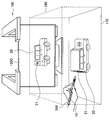
- FIG. 8 and 9 are diagrams for explaining an overview of the information processing apparatus 100 according to the present embodiment.
- the user operates the operation pen 200 and the operation cube 300 within the recognition range 190.
- the display 120C displays a state where the virtual object 20 of the car is viewed from the rear side, and the state of the virtual object 20 of the vehicle viewed from above is displayed on the projection plane 170.
- the positions and postures of the operation pen 200 and the operation cube 300 in the recognition range 190 are reflected in the positions and postures of the manipulator 10 and the virtual object 20.
- the user can perform an operation of pointing the operation pen 200 toward the operation cube 300 from above or the operation pen 200 from below.
- the virtual object 20 is illuminated with light from above, or light is illuminated from below.
- the light reference numeral 21 that illuminates the rear part of the virtual object 20 of the car is displayed.
- the operation cube 300 is a real object operated by the user.
- the operation cube 300 may be placed on the projection surface 170 as shown in FIG. 8, may be held by the user's hand, or may be supported by an arbitrary support device such as a tripod.
- the operation cube 300 may be provided with a passive marker such as a barcode for identifying each surface, an AR (Augmented Reality) marker, or the like so that the posture can be detected.
- the operation cube 300 may include an inertial sensor such as an acceleration sensor and a gyro sensor, a speed sensor, a vibration sensor, a biological sensor, and the like. Further, the operation cube 300 may include a communication unit capable of wireless communication using an arbitrary communication method such as wireless LAN, Wi-Fi, or Bluetooth, and performs transmission / reception of various data with the information processing apparatus 100. Also good.
- an inertial sensor such as an acceleration sensor and a gyro sensor, a speed sensor, a vibration sensor, a biological sensor, and the like.
- the operation cube 300 may include a communication unit capable of wireless communication using an arbitrary communication method such as wireless LAN, Wi-Fi, or Bluetooth, and performs transmission / reception of various data with the information processing apparatus 100. Also good.
- the information processing apparatus 100 according to the present embodiment has the technical features described in the above-described embodiments.
- the operation information in the present embodiment includes information indicating the positions and postures of the operation pen 200 and the operation cube 300 in the real space. Since the operation pen 200 is as described above, the operation cube 300 will be described below.
- the acquisition unit 151 recognizes an image of the operation cube 300 from the image information detected by the sensor unit 110, or recognizes the height of the operation cube 300 from the depth information detected by the sensor unit 110.
- the position and orientation of the operation cube 300 may be acquired.
- the acquisition unit 151 recognizes the identification information attached to each surface of the operation cube 300, recognizes the vertex position of the operation cube 300, and estimates the posture of the AR marker using the AR algorithm.
- the position and orientation of the operation cube 300 may be acquired.
- the acquisition unit 151 may acquire the attitude of the operation cube 300 from the information received by the communication unit 130 and detected by a sensor built in the operation cube 300. For example, the acquisition unit 151 acquires the posture of the operation cube 300 from the detection result of gravity acceleration.
- the acquisition unit 151 can acquire, as operation information, information received by the communication unit 130, such as acceleration and speed detected by a sensor built in the operation cube 300.
- the information processing apparatus 100 (for example, the generation unit 155) has a function of converting the coordinates of the operation pen 200 and the operation cube 300 in the real space into coordinates in the virtual space.
- the generation unit 155 may perform coordinate conversion using the absolute positions of the operation pen 200 and the operation cube 300, or may perform coordinate conversion using a relative position.
- the generation unit 155 When using an absolute position, the generation unit 155 reflects the position and orientation of the operation cube 300 on the position and orientation of the virtual object 20 in the virtual space, and operates on the position and orientation of the manipulator 10 in the virtual space.
- the position and orientation of the pen 200 for use may be reflected.
- the generation unit 155 converts the coordinates of each vertex of the operation cube 300 in the real space into the global coordinates of the corresponding point of the virtual object 20.
- the generation unit 155 converts the coordinates of the light emitting unit 220B of the operation pen 200 in the real space into the global coordinates of the origin 11 of the manipulator 10, and converts the coordinates of the light emitting unit 220A to the global coordinates of the gazing point 12 of the manipulator 10. Convert.
- the user holds the operation pen 200 and the operation cube 300 in the hand and moves them within the recognition range 190, as if the user moved the manipulator 10 and the virtual object 20 in the virtual space. It becomes possible to operate.
- the generation unit 155 uses the relative position and orientation of the virtual object 20 and the manipulator 10 in the virtual space as the relative position of the operation cube 300 and the operation pen 200. Also, the relationship between postures may be reflected. For example, the generation unit 155 adds the relative coordinates of the light emitting units 220B and 220A of the operation pen 200 with the operation cube 300 in the real space as a reference to the global coordinates of the virtual object 20, so that the manipulator 10 The global coordinates of the origin 11 and the gazing point 12 are calculated. Of course, the generation unit 155 calculates the global coordinates of the virtual object 20 by adding the relative coordinates of the operation cube 300 based on the operation pen 200 in the real space to the global coordinates of the operation pen 200. May be. Thereby, the user can reflect the relationship between the relative position and posture of the operation pen 200 and the operation cube 300 in the relationship between the relative position and posture of the manipulator 10 and the virtual object 20.
- the generation unit 155 generates display control information for displaying a virtual space based on operation information (first operation information) detected for the operation cube 300 (first real object). It has a function to generate. Specifically, the generation unit 155 generates display control information for performing display in which the position and orientation of the operation cube 300 are reflected in the virtual object 20 by the coordinate conversion function. As a result, the user holds the operation cube 300 in the hand and moves it within the recognition range 190, thereby causing the information processing apparatus 100 to display the virtual object 20 as if it was moved in the virtual space. be able to.
- the information processing apparatus 100 (for example, the storage control unit 153 and the storage unit 140) has a function of storing and reproducing the state of the virtual space operated by the operation pen 200 and the operation cube 300.
- the storage control unit 153 stores information indicating the position and orientation of the virtual object 20 in the storage unit 140. Then, the generation unit 155 generates display control information based on information indicating the position and orientation of the past virtual object 20 acquired from the storage unit 140 by the storage control unit 153. Thereby, the user can memorize how to move the virtual object 20 that he / she likes, and refer to it later.
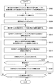
- FIG. 10 is a flowchart illustrating an example of the flow of display processing executed in the information processing apparatus 100 according to the present embodiment. This flow is a processing example when the manipulator 10 functions as a virtual light.
- step S202 the information processing apparatus 100 associates the global coordinates of the virtual object 20 in the virtual space with the operation cube 300 placed on the displayed virtual object 20.
- the user places the operation cube 300 on the virtual object 20 projected onto the projection plane 170.
- the generation unit 155 recognizes that the operation cube 300 is placed on the virtual object 20 from the image information and the depth information acquired by the acquisition unit 151, and associates the virtual object 20 with the operation cube 300.
- step S204 the information processing apparatus 100 transitions to the light control mode.
- the information processing apparatus 100 may shift to the light control mode according to the selection by the user, or may shift to the light control mode according to the recognition result of the marker attached to the operation cube 300.
- step S206 the information processing apparatus 100 generates a virtual light.
- step S208 the information processing apparatus 100 acquires the positions and orientations of the operation pen 200 and the operation cube 300.
- the acquisition unit 151 acquires the positions and orientations of the operation pen 200 and the operation cube 300 using the operation information acquisition function.
- step S210 the information processing apparatus 100 converts the positions and orientations of the operation pen 200 and the operation cube 300 into the global coordinate system of the virtual space.
- the generation unit 155 converts the coordinates of the operation pen 200 and the operation cube 300 in the real space to global coordinates in the coordinate system of the virtual space by the coordinate conversion function.
- step S212 the information processing apparatus 100 reflects the position and orientation of the operation cube 300 on the position and orientation of the virtual object 20.
- the generation unit 155 moves the global coordinates of the virtual object 20 linked to the global coordinates of the operation cube 300 converted into the coordinate system of the virtual space, and changes the attitude (rotation) of the operation cube 300 to the virtual object 20. Reflect in the attitude.
- step S214 the information processing apparatus 100 sets both ends of the operation pen 200 as the virtual light origin and gazing point.
- step S216 the information processing apparatus 100 reflects light from the virtual light in the virtual space.
- step S218 the storage control unit 153 determines whether or not to store. If it is determined to store (step S218 / YES), the process proceeds to step S220, and if it is determined not to store, the process proceeds to step S222 (NO in step S218).
- step S220 the information processing apparatus 100 stores information on the virtual light and the virtual object 20.
- the storage control unit 153 stores light parameters, information indicating the position and orientation, and information indicating the position and orientation of the virtual object 20.
- step S222 the information processing apparatus 100 determines whether or not to end the write control mode. For example, when an instruction to end the light control mode by the user is acquired (S222 / YES), the generation unit 155 ends the light control mode and turns off the virtual light. On the other hand, when the end instruction of the light control mode by the user is not acquired (S222 / NO), the process returns to step S208 again.
- FIG. 11 is a flowchart illustrating an example of the flow of display processing executed in the information processing apparatus 100 according to the present embodiment. This flow is a processing example when the manipulator 10 functions as a virtual light.
- steps S302 to S308 processing similar to the processing in steps S202 to S208 described above with reference to FIG. 10 is performed.
- step S310 the information processing apparatus 100 calculates the relative position and orientation of the operation pen 200 with respect to the operation cube 300.
- the generation unit 155 calculates the relative coordinates of the light emitting units 220B and 220A of the operation pen 200 with reference to the operation cube 300 in the real space.
- step S312 the information processing apparatus 100 converts the calculated relative position and orientation into the global coordinate system of the virtual space.
- the generation unit 155 identifies the global coordinates of the manipulator 10 by adding the relative coordinates calculated in step S ⁇ b> 310 to the global coordinates of the virtual object 20.
- steps S314 to S322 processing similar to the processing in steps S214 to S222 described above with reference to FIG. 10 is performed.
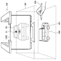
- FIG. 12 is a diagram for explaining an overview of the information processing apparatus 100 according to the present embodiment.
- the user places the model object 400 within the recognition range 190 and operates the operation pen 200.
- the model object 400 is a real object that functions as the operation cube 300 described above.
- the model object 400 has a car shape, and the car texture (pattern, color, etc.) is projection mapped.
- the example shown in FIG. 12 is an example in which the manipulator 10 functions as a camera.
- the operation pen 200 is directed to the front of the model object 400, a camera image of the virtual object 20 viewed from the front is displayed on the display 120C.
- FIG. 13 is a diagram for explaining an overview of the information processing apparatus 100 according to the present embodiment.
- the model object 400 has a car shape, and the car texture is projection-mapped.
- the example shown in this figure is an example in which the manipulator 10 functions as a light.
- light (reference numeral 21) that illuminates the front of the virtual object 20 is displayed on the display 120C.
- the model object 400 is projection-mapped with light (reference numeral 401) applied to the front.
- the information processing apparatus 100 according to the present embodiment has the technical features described in the above-described embodiments.
- the information processing apparatus 100 (for example, the generation unit 155) according to the present embodiment has a function of generating display control information for projection mapping.
- Various real objects can be considered for projection mapping.
- projection mapping may be performed on an arbitrary real object such as the user's hand, the operation pen 200, the operation cube 300, or the model object 400 existing in the recognition range 190.
- projection mapping refers to projecting an image onto a real object having a three-dimensional shape.
- the generation unit 155 first recognizes the three-dimensional shape of a real object such as the model object 400 using image information, depth information, and the like.
- the generation unit 155 generates display control information for controlling an image projected from the projector 120 based on the recognition result of the three-dimensional shape. Then, the display control unit 157 controls the projector 120 to perform projection based on the generated display control information. In this way, projection mapping to a real object is realized.
- the information processing apparatus 100 may perform projection mapping on a real object corresponding to the virtual object 20.
- real objects include the operation object cube 300 in addition to the model object 400 shown in FIGS.
- the projection mapping may be performed on the 3DCG application side.
- the information processing apparatus 100 may perform display according to the texture that is projection-mapped to the real object corresponding to the virtual object 20.
- the car texture is projection mapped onto the model object 400. Therefore, the generation unit 155 may generate display control information for displaying the virtual object 20 on which the projection-mapped texture is drawn on the surface.
- a camera image of the virtual object 20 with the projection-mapped texture drawn on the surface is viewed from the front is displayed on the display 120C. The same applies to lights and the like. Thereby, the information processing apparatus 100 can reduce the difference between the state of the real space and the state of the virtual space.
- the generation unit 155 may acquire what texture is projection-mapped from an entity that performs projection mapping (for example, the display control unit 157 or the 3DCG application), or may acquire it from an image recognition result. Also good.
- the information processing apparatus 100 may have a function of displaying the above-described virtual tool parameters.
- the generation unit 155 may generate the display control information for displaying the parameter in a place related to the operation pen 200.
- Examples of the location where the parameter is related to the operation pen 200 include the operation pen 200 itself and the user's hand holding the operation pen 200.
- the projector 120 performs projection mapping of parameters on the user's hand holding the operation pen 200. Accordingly, the user can easily grasp the coordinate information of the manipulator 10, the intensity of the light, and the like while operating the operation pen 200.
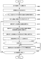
- FIG. 14 is a flowchart illustrating an example of the flow of display processing executed in the information processing apparatus 100 according to the present embodiment. This flow is a processing example when the manipulator 10 functions as a virtual camera.
- step S402 the information processing apparatus 100 transitions to the camera control mode.
- the information processing apparatus 100 may transition to the camera control mode according to the selection by the user.
- step S404 the information processing apparatus 100 generates a virtual camera.
- the user displays parameters such as the focal length of the camera on the projection plane 170 and designates the parameters. In addition to designation by the user, default parameters may be used.
- the acquisition unit 151 acquires information indicating the designated parameter.
- the generation unit 155 determines the action of the virtual camera.
- step S406 the information processing apparatus 100 acquires the position and orientation of the model object 400 placed on the table 180.
- the acquisition unit 151 acquires the position and orientation of the model object 400 using the operation information acquisition function.
- step S408 the information processing apparatus 100 maps the virtual object to the model object 400.
- the information processing apparatus 100 may perform projection mapping of an arbitrary texture on the model object 400.
- the texture to be mapped may be selected by the user from the GUI menu, for example.
- step S410 the information processing apparatus 100 acquires the position and orientation of the operation pen 200.
- step S412 the information processing apparatus 100 converts the relationship between the position and orientation of the operation pen 200 and the model object 400 into a coordinate system in the virtual space.
- the information processing apparatus 100 may perform coordinate conversion using the absolute positions of the operation pen 200 and the model object 400, or may perform coordinate conversion using a relative position.
- step S414 the information processing apparatus 100 sets both ends of the operation pen 200 as the virtual camera origin and gaze point.
- the generation unit 155 sets the origin 11 and the gazing point 12 of the manipulator 10 as the origin and the gazing point of the camera by the virtual space display function.
- step S416 the information processing apparatus 100 reflects it in the camera view of the virtual space.
- the generation unit 155 displays the state of the virtual space captured by the virtual camera from the origin 11 toward the gazing point 12 by the virtual space display function.
- step S4108 the storage control unit 153 determines whether or not to store. If it is determined to store (step S418 / YES), the process proceeds to step S420, and if it is determined not to store, the process proceeds to step S422 (step S418 / NO).
- step S420 the information processing apparatus 100 stores information on the virtual camera and the virtual object 20.
- the storage control unit 153 stores information indicating camera parameters, position and orientation, and information indicating the position and orientation of the virtual object 20.
- step S422 the information processing apparatus 100 determines whether to end the camera control mode. For example, when an instruction to end the camera control mode by the user is acquired (S422 / YES), the generation unit 155 ends the camera control mode and turns off the virtual camera. On the other hand, when an instruction to end the camera control mode by the user is not acquired (S422 / NO), the process returns to step S410 again.
- FIG. 15 is a flowchart illustrating an example of the flow of display processing executed in the information processing apparatus 100 according to the present embodiment.
- step S502 the information processing apparatus 100 transitions to the light control mode.
- step S504 the information processing apparatus 100 generates a virtual light.
- steps S506 to S512 processing similar to the processing in steps S406 to S412 described above with reference to FIG. 14 is performed.
- step S514 the information processing apparatus 100 sets both ends of the operation pen 200 as the virtual light origin and gazing point.
- step S5166 the information processing apparatus 100 reflects light from the virtual light in the virtual space.
- steps S518 to S522 processing similar to the processing in steps S418 to S422 described above with reference to FIG. 14 is performed.
- the third embodiment has been described above.
- FIG. 16 is a diagram for explaining an overview of the information processing apparatus 100 according to the present embodiment.
- the user operates the operation pens 200 ⁇ / b> A and 200 ⁇ / b> B within the recognition range 190.
- the manipulator 10 corresponding to the operation pen 200A functions as a camera
- the manipulator 10 corresponding to the operation pen 200B functions as a light.
- the operation pen 200A is directed to the rear side of the virtual object 20 displayed on the projection plane 170, a camera image of the virtual object 20 viewed from the rear side is displayed on the display 120C.
- the operation pen 200 is directed from behind to the virtual object 20 displayed on the projection plane 170, light (reference numeral 21) that illuminates the rear part of the virtual object 20 is displayed.
- the generation unit 155 generates display control information based on each of the plurality of operation information detected for the plurality of operation pens 200. As a result, as shown in FIG. 16, it is possible to display a virtual space reflecting an operation using a plurality of operation pens 200.
- the plurality of manipulators 10 function as different virtual tools, but the present technology is not limited to such an example.
- a plurality of manipulators 10 may function as the same virtual tool.
- the information processing apparatus 100 has a storage / reproduction function, and refers to information indicating the state of the virtual space stored in the storage unit 140 (for example, information on virtual lights, cameras, and virtual objects 20). Thus, the situation of the virtual space can be reproduced.
- the information processing apparatus 100 according to the present embodiment can smoothly store or reproduce the state of the virtual space by the camera shake correction function.
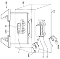
- FIG. 17 is a diagram for explaining an example of the camera shake correction function according to the present embodiment.
- the user is holding the operation pen 200 with a finger.
- the operation pen 200 shakes when the user presses the button 210B.
- the stored coordinates can be affected. Therefore, the storage control unit 153 may store the coordinates of the manipulator 10 at the timing when the user releases the finger along the operation pen 200.
- the operation pen 200 may include a touch sensor 210D and can detect whether a finger is in contact with or separated from the touch pen. Thereby, the shaking of the operation pen 200 is reduced, and the hand shake is reduced.
- the storage control unit 153 may correct and store the coordinates so as to follow the grid in the coordinate space of the 3DCG application. In that case, the camera shake correction function is further improved.
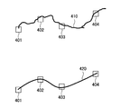
- FIG. 18 is a diagram for explaining an example of the camera shake correction function according to the present embodiment.
- information of discrete coordinates 401 to 404 is stored in the storage unit 140.
- the information processing apparatus 100 can generate a trajectory 420 at the time of reproduction by interpolating between each coordinate with a spline curve or the like when an actual hand movement passes through the trajectory 410. Then, the information processing apparatus 100 may reproduce the state of the virtual space according to the trajectory 420.
- the information processing apparatus 100 may have a camera shake correction function related to the operation information acquisition function in addition to the storage / reproduction function.
- the information processing apparatus 100 may perform motion prediction using a Kalman filter based on the current position of the operation pen 200 and the state one step before and correct the camera shake. Further, the information processing apparatus 100 may dynamically control the correction degree by the camera shake correction function in accordance with the scale of the virtual space.
- the information processing apparatus 100 sounds a sound effect of 10 levels or the like according to the height of the operation pen 200, or projects information indicating the position of the operation pen 200 or the operation cube 300 on the operation cube 300. You may do it. As a result, the user can intuitively and finely perform an operation in consideration of coordinates such as horizontal movement.
- the ON / OFF of the camera shake correction function, the correction degree, and the like may be arbitrarily set by the user.
- FIG. 19 is a block diagram illustrating an example of a hardware configuration of the information processing apparatus according to the present embodiment. Note that the information processing apparatus 900 illustrated in FIG. 19 can realize the information processing apparatus 100 illustrated in FIG. 5, for example. Information processing by the information processing apparatus 100 according to the present embodiment is realized by cooperation of software and hardware described below.
- the information processing apparatus 900 includes a CPU (Central Processing Unit) 901, a ROM (Read Only Memory) 902, a RAM (Random Access Memory) 903, and a host bus 904a.
- the information processing apparatus 900 includes a bridge 904, an external bus 904b, an interface 905, an input device 906, an output device 907, a storage device 908, a drive 909, a connection port 911, and a communication device 913.
- the information processing apparatus 900 may include a processing circuit such as a DSP or an ASIC in place of or in addition to the CPU 901.
- the CPU 901 functions as an arithmetic processing unit and a control unit, and controls the overall operation in the information processing apparatus 900 according to various programs. Further, the CPU 901 may be a microprocessor.
- the ROM 902 stores programs used by the CPU 901, calculation parameters, and the like.
- the RAM 903 temporarily stores programs used in the execution of the CPU 901, parameters that change as appropriate during the execution, and the like.
- the CPU 901 can form the control unit 150 shown in FIG.
- the CPU 901, ROM 902, and RAM 903 are connected to each other by a host bus 904a including a CPU bus.
- the host bus 904 a is connected to an external bus 904 b such as a PCI (Peripheral Component Interconnect / Interface) bus via a bridge 904.
- an external bus 904 b such as a PCI (Peripheral Component Interconnect / Interface) bus
- PCI Peripheral Component Interconnect / Interface
- the host bus 904a, the bridge 904, and the external bus 904b do not necessarily have to be configured separately, and these functions may be mounted on one bus.
- the input device 906 is realized by a device in which information is input by the user, such as a mouse, a keyboard, a touch panel, a button, a microphone, a switch, and a lever. Further, the input device 906 may be a device that detects an action of a user or a real object in a sensing range, such as an image sensor that can capture an image and a depth sensor that can acquire depth information.
- the input device 906 may be, for example, a remote control device using infrared rays or other radio waves, or may be an external connection device such as a mobile phone or a PDA that supports the operation of the information processing device 900. .
- the input device 906 may include, for example, an input control circuit that generates an input signal based on information input by the user using the above-described input means and outputs the input signal to the CPU 901.
- a user of the information processing apparatus 900 can input various data and instruct a processing operation to the information processing apparatus 900 by operating the input device 906.
- the input device 906 can form, for example, the sensor unit 110 shown in FIG.
- the output device 907 is formed of a device that can notify the user of the acquired information visually or audibly.
- Such devices include laser projectors, LED projectors, CRT display devices, liquid crystal display devices, plasma display devices, EL display devices, display devices such as lamps, audio output devices such as speakers and headphones, printer devices, and the like.
- the output device 907 outputs results obtained by various processes performed by the information processing device 900.
- the display device visually displays results obtained by various processes performed by the information processing device 900 in various formats such as text, images, tables, and graphs.
- the audio output device converts an audio signal composed of reproduced audio data, acoustic data, and the like into an analog signal and outputs it aurally.
- the display device can form, for example, the display unit 120 shown in FIG.
- the storage device 908 is a data storage device formed as an example of a storage unit of the information processing device 900.
- the storage apparatus 908 is realized by, for example, a magnetic storage device such as an HDD, a semiconductor storage device, an optical storage device, a magneto-optical storage device, or the like.
- the storage device 908 may include a storage medium, a recording device that records data on the storage medium, a reading device that reads data from the storage medium, a deletion device that deletes data recorded on the storage medium, and the like.
- the storage device 908 stores programs executed by the CPU 901, various data, various data acquired from the outside, and the like.
- the storage device 908 can form the storage unit 140 shown in FIG. 5, for example.
- the drive 909 is a storage medium reader / writer, and is built in or externally attached to the information processing apparatus 900.
- the drive 909 reads information recorded on a removable storage medium such as a magnetic disk, an optical disk, a magneto-optical disk, or a semiconductor memory, and outputs the information to the RAM 903.
- the drive 909 can also write information to a removable storage medium.
- connection port 911 is an interface connected to an external device, and is a connection port with an external device capable of transmitting data by USB (Universal Serial Bus), for example.
- USB Universal Serial Bus
- the communication device 913 is a communication interface formed by a communication device or the like for connecting to the network 920, for example.
- the communication device 913 is, for example, a communication card for wired or wireless LAN (Local Area Network), LTE (Long Term Evolution), Bluetooth (registered trademark), or WUSB (Wireless USB).
- the communication device 913 may be a router for optical communication, a router for ADSL (Asymmetric Digital Subscriber Line), a modem for various communication, or the like.
- the communication device 913 can transmit and receive signals and the like according to a predetermined protocol such as TCP / IP, for example, with the Internet and other communication devices.
- the communication device 913 can form, for example, the communication unit 130 illustrated in FIG.
- the network 920 is a wired or wireless transmission path for information transmitted from a device connected to the network 920.
- the network 920 may include a public line network such as the Internet, a telephone line network, and a satellite communication network, various LANs including the Ethernet (registered trademark), a wide area network (WAN), and the like.
- the network 920 may include a dedicated line network such as an IP-VPN (Internet Protocol-Virtual Private Network).
- IP-VPN Internet Protocol-Virtual Private Network
- each of the above components may be realized using a general-purpose member, or may be realized by hardware specialized for the function of each component. Therefore, it is possible to change the hardware configuration to be used as appropriate according to the technical level at the time of carrying out this embodiment.
- a computer program for realizing each function of the information processing apparatus 900 according to the present embodiment as described above can be produced and mounted on a PC or the like.
- a computer-readable recording medium storing such a computer program can be provided.
- the recording medium is, for example, a magnetic disk, an optical disk, a magneto-optical disk, a flash memory, or the like.
- the above computer program may be distributed via a network, for example, without using a recording medium.
- the information processing apparatus 100 includes the operation information detected for a real object (for example, the operation cube 300 or the model object 400) corresponding to the virtual object in the virtual space, and the virtual space.
- the virtual space is displayed based on the second operation information detected for the real object (for example, the operation pen 200) corresponding to the virtual tool.
- the user can intuitively and easily operate the virtual object 20 and the manipulator 10 in the virtual space using, for example, the positional relationship between the operation cube 300 and the operation pen 200.
- the user operates the operation pen 200 to change the position and orientation of the light, while operating the operation cube 300 to change the position and orientation of the virtual object 20 separately. It becomes possible to operate simultaneously.
- the information processing apparatus 100 may perform projection mapping on a real object. Furthermore, the information processing apparatus 100 may perform display in accordance with the projection mapped texture. Thereby, the user can use the 3DCG application in a more intuitive operation environment using the model object 400 to which the texture is mapped.
- the information processing apparatus 100 may perform display reflecting the use of a virtual tool for a virtual object.
- the user can cause the manipulator 10 corresponding to the operation pen 200 to function as a light or as a camera.
- the present technology facilitates confirmation of the viewpoint, for example, confirming the appearance from the human eye in an architectural model, and can be used for presentation to a client as well as for production.
- the present technology can also be used for medical purposes, for example, confirming how the endoscope is viewed in a body cavity. Further, the present technology can be used, for example, for musical instrument trials by causing the manipulator 10 to function as a drumstick.
- each device described in this specification may be realized as a single device, or a part or all of the devices may be realized as separate devices.
- the storage unit 140 and the control unit 150 are connected to the sensor unit 110, the display unit 120, and the communication unit 130 via a network or the like. It may be provided.
- the generation unit according to any one of (2) to (7), wherein the generation unit generates the display control information for performing display reflecting the use of the virtual tool on the virtual object.
- Information processing device (9) The information processing apparatus according to (8), wherein the virtual tool is a light.
- the parameter related to the action of the tool includes any one of a light type, a light color, an intensity, a cone angle, a peripheral angle, a drop-off, a shadow color, and an effect.
- Information processing device (11) The information processing apparatus according to (8), wherein the virtual tool is a camera.
- the parameter relating to the action of the tool includes any one of a camera type, a camera angle of view, a camera focal length, a camera depth of field, a zoom, and a camera weight.
- the parameter relating to the action of the tool includes any one of the type of particle emitting device, the shape, size, number of discharges, discharge direction, discharge angle, discharge speed, discharge rate, gravity, and viscosity of the particle (13 ).
- the generation unit is configured to determine a relative position and posture between the first real object and the second real object in a relative position and posture between the virtual object and the virtual tool in the virtual space.
- the information processing apparatus according to any one of (2) to (14), wherein the relationship is reflected.
- the generating unit reflects the position and posture of the first real object in the position and posture of the virtual object in the virtual space, and adds the second real object to the position and posture of the virtual tool in the virtual space.
- the information processing apparatus according to any one of (2) to (15), wherein the position and orientation of the object are reflected.
- the information processing apparatus further includes a storage control unit that stores information indicating the position and posture of the virtual object and the virtual tool in a storage unit, The information processing apparatus according to any one of (2) to (16), wherein the generation unit generates the display control information based on past information acquired from the storage unit by the storage control unit. .
- the generation unit generates the display control information based on each of the plurality of second operation information detected for the plurality of second real objects, and any one of (2) to (17) The information processing apparatus according to item.
Landscapes
- Engineering & Computer Science (AREA)
- General Engineering & Computer Science (AREA)
- Theoretical Computer Science (AREA)
- Physics & Mathematics (AREA)
- General Physics & Mathematics (AREA)
- Human Computer Interaction (AREA)
- Computer Graphics (AREA)
- Software Systems (AREA)
- Architecture (AREA)
- Computer Hardware Design (AREA)
- Multimedia (AREA)
- Geometry (AREA)
- User Interface Of Digital Computer (AREA)
- Processing Or Creating Images (AREA)
- Position Input By Displaying (AREA)
Abstract
【課題】より直感的な3DCGアプリケーションの操作環境を提供することが可能な情報処理装置、情報処理方法及びプログラムを提供する。 【解決手段】仮想空間における仮想オブジェクトに対応する第1の実オブジェクトについて検出された第1の操作情報と、前記仮想空間における仮想的な道具に対応する第2の実オブジェクトについて検出された第2の操作情報とに基づいて、前記仮想空間の表示を行うための表示制御情報を生成する生成部、を備える情報処理装置。
Description
本開示は、情報処理装置、情報処理方法及びプログラムに関する。
近年、3次元コンピュータグラフィックス(3DCG)が様々な分野で活用されている。ユーザは、3DCGアプリケーションを操作することで、仮想空間内に3DCGを生成したり、仮想空間を任意の視点から鑑賞したりすることができる。その際、ユーザは、仮想空間における位置をX座標、Y座標及びZ座標の3つの座標で特定したり、様々なパラメータを指定したりする等、複雑な操作を要されていた。このため、3DCGアプリケーションの操作環境をより良くするための技術が開発されている。
例えば、下記特許文献1では、実空間における機器の姿勢に応じて、仮想空間内に定義された視点の位置を決定する技術が開示されている。
しかし、上記特許文献1では、実空間における機器の姿勢により、仮想空間における視点が操作可能になるに留まっていた。仮想空間では、視点などのユーザの操作対象となる作用点の他に、仮想オブジェクトが存在する。この仮想オブジェクトも、実空間における直感的な操作により操作可能になることが望ましい。そこで、本開示では、より直感的な3DCGアプリケーションの操作環境を提供することが可能な、新規かつ改良された情報処理装置、情報処理方法及びプログラムを提案する。
本開示によれば、仮想空間における仮想オブジェクトに対応する第1の実オブジェクトについて検出された第1の操作情報と、前記仮想空間における仮想的な道具に対応する第2の実オブジェクトについて検出された第2の操作情報とに基づいて、前記仮想空間の表示を行うための表示制御情報を生成する生成部、を備える情報処理装置が提供される。
また、本開示によれば、仮想空間における仮想オブジェクトに対応する第1の実オブジェクトについて検出された第1の操作情報と、前記仮想空間における仮想的な道具に対応する第2の実オブジェクトについて検出された第2の操作情報とに基づいて、前記仮想空間の表示を行うための表示制御情報を生成すること、を含むプロセッサにより実行される情報処理方法が提供される。
また、本開示によれば、コンピュータを、仮想空間における仮想オブジェクトに対応する第1の実オブジェクトについて検出された第1の操作情報と、前記仮想空間における仮想的な道具に対応する第2の実オブジェクトについて検出された第2の操作情報とに基づいて、前記仮想空間の表示を行うための表示制御情報を生成する生成部、として機能させるためのプログラムが提供される。
以上説明したように本開示によれば、より直感的な3DCGアプリケーションの操作環境を提供することが可能である。なお、上記の効果は必ずしも限定的なものではなく、上記の効果とともに、または上記の効果に代えて、本明細書に示されたいずれかの効果、または本明細書から把握され得る他の効果が奏されてもよい。
以下に添付図面を参照しながら、本開示の好適な実施の形態について詳細に説明する。なお、本明細書及び図面において、実質的に同一の機能構成を有する構成要素については、同一の符号を付することにより重複説明を省略する。
また、本明細書及び図面において、実質的に同一の機能構成を有する要素を、同一の符号の後に異なるアルファベットを付して区別する場合もある。例えば、実質的に同一の機能構成を有する複数の要素を、必要に応じて情報処理装置100A、100B及び100Cのように区別する。ただし、実質的に同一の機能構成を有する複数の要素の各々を特に区別する必要がない場合、同一符号のみを付する。例えば、情報処理装置100A、100B及び100Cを特に区別する必要が無い場合には、単に情報処理装置100と称する。
なお、説明は以下の順序で行うものとする。
1.概要
1.1.はじめに
1.2.技術的課題
2.構成例
2.1.外観構成例
2.2.機能構成例
3.第1の実施形態
3.1.技術的特徴
3.2.動作処理例
4.第2の実施形態
4.1.技術的特徴
4.2.動作処理例
5.第3の実施形態
5.1.技術的特徴
5.2.動作処理例
6.第4の実施形態
7.第5の実施形態
8.ハードウェア構成例
9.まとめ
1.概要
1.1.はじめに
1.2.技術的課題
2.構成例
2.1.外観構成例
2.2.機能構成例
3.第1の実施形態
3.1.技術的特徴
3.2.動作処理例
4.第2の実施形態
4.1.技術的特徴
4.2.動作処理例
5.第3の実施形態
5.1.技術的特徴
5.2.動作処理例
6.第4の実施形態
7.第5の実施形態
8.ハードウェア構成例
9.まとめ
<<1.概要>>
<1.1.はじめに>
まず、図1及び図2を参照して、3DCGアプリケーションにおける操作環境について説明する。図1及び図2は、3DCGアプリケーションにおける操作環境を説明するための図である。
<1.1.はじめに>
まず、図1及び図2を参照して、3DCGアプリケーションにおける操作環境について説明する。図1及び図2は、3DCGアプリケーションにおける操作環境を説明するための図である。
図1では、3DCGアプリケーションの仮想空間の一例を示している。ユーザは、マニピュレーター10を操作することで、多様な作用を仮想空間に与えることができる。マニピュレーター10は、方向性を有し、マニピュレーター10の向く方向へ作用を与えることができる。また、マニピュレーター10は、仮想的な道具として機能し得る。例えば、図1に示した例では、マニピュレーター10は、ライトとして機能するライト用マニピュレーターであり、マニピュレーター10の位置から仮想オブジェクト20に向けてスポットライトを照射することが可能である。ユーザは、ライト用マニピュレーターの他、移動用、変形用又は着色用のマニピュレーターといった、多様な種類のマニピュレーターを用いて、仮想オブジェクト20の移動、変形又は着色といった多様な作用を仮想空間に与えることができる。
図2に示すように、マニピュレーター10の方向13は、原点11及び注視点12によって特定される。そのため、ユーザは、マニピュレーター10の方向13を操作するために、原点11及び注視点12の座標(X座標、Y座標及びZ座標)をそれぞれ指定していた。
<1.2.技術的課題>
ここで、ユーザがマウス又はキーボード等で操作する場合、原点11及び注視点12を同時に操作することは困難であった。また、原点11及び注視点12を操作するためには、X座標、Y座標及びZ座標の3つの座標をそれぞれ指定することが要される。このため、マニピュレーター10の方向13を制御するための操作は煩雑であった。
ここで、ユーザがマウス又はキーボード等で操作する場合、原点11及び注視点12を同時に操作することは困難であった。また、原点11及び注視点12を操作するためには、X座標、Y座標及びZ座標の3つの座標をそれぞれ指定することが要される。このため、マニピュレーター10の方向13を制御するための操作は煩雑であった。
また、仮想オブジェクト20に関しては、ユーザは、例えば移動用マニピュレーターを介して仮想オブジェクト20を移動させる等の操作を行っていた。このため、仮想オブジェクト20を操作することも、マニピュレーター10と同様に煩雑になり得る。さらに、マニピュレーター10をライト等の仮想的な道具として機能させて、ライトの位置及び向きを操作しながら仮想オブジェクト20の位置及び向きを操作するような、マニピュレーター10及び仮想オブジェクト20を別々且つ同時に操作することは困難であった。
そこで、上記事情を一着眼点として、本開示の一実施形態に係る情報処理システムを創作するに至った。本実施形態に係る情報処理システムは、より直感的な3DCGアプリケーションの操作環境を提供することが可能である。
<<2.構成例>>
以下では、図3~図5を参照して、各実施形態に共通する情報処理システムの構成例を説明する。
以下では、図3~図5を参照して、各実施形態に共通する情報処理システムの構成例を説明する。
<2.1.外観構成例>
図3は、本実施形態に係る情報処理システム1の外観構成の一例を示す図である。図3に示すように、情報処理装置100及び操作用ペン200を含む。
図3は、本実施形態に係る情報処理システム1の外観構成の一例を示す図である。図3に示すように、情報処理装置100及び操作用ペン200を含む。
情報処理装置100は、可動式のアーム160をひとつ以上有する。アーム160A及び160Bは、それぞれセンサ部110A及び110B、並びに表示部120A及び120Bを有する。センサ部110A及び110Bは、画像(静止画像/動画像)を撮像可能な画像センサ、及び深度情報(奥行き方向の距離)を取得可能な深度センサを含み、テーブル180上の認識範囲190の様子を検出可能である。画像センサは、例えばRGBカメラにより実現されてもよく、深度センサは、例えばIR(infrared)ステレオカメラにより実現されてもよい。
表示部120A及び120Bは、例えばプロジェクタにより実現され、投影面170に画像を投影する。投影される画像は、例えば3DCGアプリケーションの操作画面である。投影面170は、タッチパネルとしての機能を有していてもよく、操作用ペン200による接触を感知してもよい。プロジェクタ120A及び120Bは、同じ画像を互いに投影位置を合わせて投影面170に投影する。異なる位置から複数の投影光が照射されるので、投影面170の上に存在するユーザの手等の障害物があっても、投影面170の上に存在するユーザの手等の障害物によって出来る影が薄くなるため、影の位置にある投影面上の画像の視認性を向上させることが出来る。
情報処理装置100は、表示部120Cをさらに有していてもよい。表示部120Cは、例えばディスプレイにより実現され、画像を表示する。表示される画像は、例えば3DCGアプリケーションの操作画面である。プロジェクタ120A及び120Bとディスプレイ120Cとは、それぞれ異なる画像を表示してもよいし、同一の画像を表示してもよい。例えば、図3に示した例では、プロジェクタ120A及び120Bとディスプレイ120Cとは、車の仮想オブジェクト20を異なる角度から見た様子を表示している。
操作用ペン200は、ユーザにより操作される装置である。操作用ペン200は、図3に示したようにユーザの手で持たれてもよいし、投影面170上に置かれてもよいし、三脚等の任意の支持器により支持されてもよい。以下、図4を参照して、操作用ペン200の外観構成例を詳しく説明する。
図4は、本実施形態に係る操作用ペン200の外観構成の一例を示す図である。図4に示すように、操作用ペン200には、複数の入力部210及び複数の発光部220が設けられている。
入力部210は、ユーザ入力を受け付ける機能を有する。図4に示した例では、入力部210はボタンである。例えば、ボタン210Aは、マウスの左クリックに相当する。ボタン210Bは、マウスの右クリックに相当する。ボタン210Cは、任意の機能が割り当てられる汎用ボタンである。他にも、入力部210は、タッチセンサやトグル、スライダー等により実現されてもよい。
発光部220は、発光する機能を有する。例えば、発光部220は、LED(light emitting diode)又はIR LED等により実現される。発光部220が発光することで、発光しない場合と比較して、センサ部110による操作用ペン200の姿勢の検出が容易になる。なお、操作用ペン200の姿勢の検出が容易にするために、発光部220に代えて、又は併せて、バーコード等のパッシブマーカーが操作用ペン200に付されていてもよい。
操作用ペン200は、他にも、加速度センサ及びジャイロセンサ等の慣性センサ、速度センサ、振動センサ、生体センサ等を有していてもよい。また、操作用ペン200は、無線LAN(Local Area Network)、Wi-Fi(登録商標)又はBluetooth(登録商標)等の任意の通信方式を用いて無線通信可能な通信部を有してもよく、情報処理装置100と各種データの送受信を行ってもよい。
ユーザは、投影面170に投影された、又は表示部120に表示された3DCGアプリケーションの操作画面を操作用ペン200でタッチしたり、タッチしながら動かしたりすることで、直感的に3DCGアプリケーションの操作を行うことができる。さらに、ユーザは、認識範囲190内で操作用ペン200を操作することで、操作用ペン200の位置及び姿勢に応じた直感的な3DCGアプリケーションの操作を行うことができる。
以上、操作用ペン200の外観構成例を説明した。続いて、図5を参照して、情報処理装置100の機能構成例を説明する。
<2.2.機能構成例>
図5は、本実施形態に係る情報処理装置100の論理的な構成の一例を示すブロック図である。図5に示すように、情報処理装置100は、センサ部110、表示部120、通信部130、記憶部140及び制御部150を含む。
図5は、本実施形態に係る情報処理装置100の論理的な構成の一例を示すブロック図である。図5に示すように、情報処理装置100は、センサ部110、表示部120、通信部130、記憶部140及び制御部150を含む。
センサ部110は、認識範囲190の状態を検出する機能を有する。上述したように、センサ部110は、例えば画像センサ及び深度センサを含み、認識範囲190内に存在する操作用ペン200等の実オブジェクトに関する画像情報及び深度情報を検出する。センサ部110は、検出した情報を制御部150へ出力する。
表示部120は、情報を表示する機能を有する。上述したように、表示部120は、プロジェクタ及びディスプレイにより実現され得る。表示部120は、制御部150による制御に基づき、3DCGアプリケーションの操作画面等を出力する。
通信部130は、有線/無線により外部機器との間でデータの送受信を行うための通信モジュールである。通信部130は、無線LAN、Wi-Fi又はBluetooth等の任意の通信方式を用いて操作用ペン200と通信する。例えば、通信部130は、入力部210への入力情報や、操作用ペン200に内蔵された慣性センサにより検出された情報を受信し得る。通信部130は、受信した情報を制御部150へ出力する。
記憶部140は、所定の記録媒体に対してデータの記録再生を行う部位である。例えば、記憶部140は、ユーザにからの記憶指示に基づいて、操作内容を示す情報を記憶する。
制御部150は、演算処理装置及び制御装置として機能し、各種プログラムに従って情報処理装置100内の動作全般を制御する。図5に示すように、制御部150は、取得部151、記憶制御部153、生成部155及び表示制御部157として機能する。取得部151は、ユーザによる操作の内容を示す操作情報を取得する機能を有する。記憶制御部153は、記憶部140に情報を記憶したり、記憶部140に記憶された情報を読み出したりする機能を有する。生成部155は、表示部120に表示させる内容を規定した表示制御情報を生成する機能を有する。なお、表示制御情報は、RGB信号又はHDMI(登録商標)信号等の画像表示のための信号であってもよいし、HTMLファイル等であってもよい。表示制御部157は、生成部155により生成された表示制御情報に基づく表示を行うよう表示部120を制御する機能を有する。
なお、情報処理装置100は、3DCGアプリケーションから座標を取得して、取得した座標に基づいて各種情報処理を行う。制御部150と3DCGアプリケーションとの間で行われる座標の入力及び出力等の通信は、3DCGアプリケーションのAPI又はプラグイン等により行われ得る。
以上、本実施形態に係る情報処理装置100の機能構成例を説明した。続いて、各実施形態について詳細に説明する。
<<3.第1の実施形態>>
まず、図6を参照して、本実施形態に係る情報処理装置100の概要を説明する。
まず、図6を参照して、本実施形態に係る情報処理装置100の概要を説明する。
図6は、本実施形態に係る情報処理装置100の概要を説明するための図である。図6に示すように、ユーザは、認識範囲190内で操作用ペン200を操作する。また、ディスプレイ120Cには、車の仮想オブジェクト20を側面後方から見た様子が表示され、投影面170には車の仮想オブジェクト20を上から見た様子が表示されている。本実施形態は、認識範囲190における操作用ペン200の位置及び姿勢が、マニピュレーター10の位置及び姿勢に反映される形態である。
以下、本実施形態に係る情報処理装置100が有する技術的特徴を説明する。
<3.1.技術的特徴>
(操作情報取得機能)
情報処理装置100(例えば、取得部151)は、ユーザによる操作の内容を示す操作情報を取得する機能を有する。本実施形態における操作情報は、操作用ペン200等のユーザにより操作される実オブジェクトの実空間における位置及び姿勢を示す情報を含む。
(操作情報取得機能)
情報処理装置100(例えば、取得部151)は、ユーザによる操作の内容を示す操作情報を取得する機能を有する。本実施形態における操作情報は、操作用ペン200等のユーザにより操作される実オブジェクトの実空間における位置及び姿勢を示す情報を含む。
例えば、取得部151は、センサ部110により検出された画像情報から操作用ペン200を画像認識したり、センサ部110により検出された深度情報から操作用ペン200の高さを認識したりすることで、操作用ペン200の位置及び姿勢を取得してもよい。その際、取得部151は、操作用ペン200の両端(発光部220A及び220B)の座標を特定することで、操作用ペン200の位置及び姿勢を取得してもよい。
また、取得部151は、通信部130により受信された、操作用ペン200が内蔵するセンサにより検出された情報から、操作用ペン200の姿勢を取得してもよい。例えば、取得部151は、重力加速度の検出結果から操作用ペン200の姿勢を取得する。
他にも、取得部151は、通信部130により受信された、操作用ペン200の入力部210への入力情報や、操作用ペン200に内蔵されたセンサにより検出された加速度や速度等の情報を、操作情報として取得し得る。
また、例えばユーザの指等の他の実オブジェクトが、操作用ペン200として機能してもよい。その場合、操作情報は、ユーザの指及び姿勢を示す情報となる。取得部151は、ユーザの指の付け根と先端の座標を、操作用ペン200の両端と同様に特定することで、操作情報を取得し得る。
(座標変換機能)
情報処理装置100(例えば、生成部155)は、実空間における座標を、仮想空間における座標に変換する機能を有する。
情報処理装置100(例えば、生成部155)は、実空間における座標を、仮想空間における座標に変換する機能を有する。
例えば、生成部155は、実空間における操作用ペン200の両端の座標を、仮想空間におけるマニピュレーター10の原点11及び注視点12の座標に変換する。より詳しくは、生成部155は、マニピュレーター10の位置及び姿勢(原点11及び注視点12の座標)に、操作用ペン200の位置及び姿勢(発光部220A及び220Bの座標)を反映させる。例えば、生成部155は、実空間における操作用ペン200の発光部220Bの座標をマニピュレーター10の原点11の座標に変換して、発光部220Aの座標をマニピュレーター10の注視点12の座標に変換する。これにより、ユーザは、操作用ペン200を手に持って認識範囲190内で動かすことで、あたかもマニピュレーター10を手に持って仮想空間内で動かすかのように操作することが可能となる。
なお、変換先の座標は、特に言及しない限りグローバル座標であるものとする。なお、グローバル座標とは、仮想空間における絶対的な位置を示す座標である。これに対し、ローカル座標とは、仮想空間における任意の位置(単なる座標、又は仮想オブジェクト)を基準とした相対的な位置を示す座標である。
生成部155は、仮想空間の表示の拡大又は縮小に合わせた座標変換を行ってもよい。例えば、生成部155は、認識範囲190内における操作用ペン200の移動距離を、仮想空間の縮尺に合わせた仮想空間内の移動距離に変換する。例えば、仮想空間を拡大して仮想オブジェクト20の一部を表示している場合、マニピュレーター10の可動域はその一部に限定され、仮想空間を縮小して仮想オブジェクト20の全体を表示している場合、マニピュレーター10の可動域はその全体に渡る。
(仮想空間表示機能)
情報処理装置100(例えば、生成部155及び表示制御部157)は、仮想空間の表示を行う機能を有する。以下では、生成部155が表示制御情報を生成して、表示制御部157が表示制御情報に基づく表示を行うよう表示部120を制御することを、単に表示を行う、とも称する。
情報処理装置100(例えば、生成部155及び表示制御部157)は、仮想空間の表示を行う機能を有する。以下では、生成部155が表示制御情報を生成して、表示制御部157が表示制御情報に基づく表示を行うよう表示部120を制御することを、単に表示を行う、とも称する。
例えば、生成部155は、操作用ペン200(第2の実オブジェクト)について検出された操作情報(第2の操作情報)に基づいて、仮想空間の表示を行うための表示制御情報を生成する機能を有する。具体的には、生成部155は、座標変換機能により操作用ペン200の位置及び姿勢をマニピュレーター10に反映させた表示を行うための表示制御情報を生成する。これにより、ユーザは、操作用ペン200を手に持って認識範囲190内で動かすことで、あたかもマニピュレーター10を手に持って仮想空間内で動かしたかのような表示を、情報処理装置100にさせることができる。なお、操作用ペン200のペン軸方向の回転は、マニピュレーター10に反映されてもよいし反映されなくてもよい。反映されるか否かは、ユーザにより設定されてもよい。また、操作用ペン200の所定の軸(方向)に対しての移動(変化)をマニピュレーター10の移動に変換される割合を、小さくする、大きくする又はゼロにする(動かさない)といった調整が任意になされてもよい。
さらに、生成部155は、操作用ペン200を仮想空間における仮想的な道具に対応させてもよい。具体的には、生成部155は、マニピュレーター10に仮想的な道具としての機能をもたせてもよい。そして、生成部155は、仮想オブジェクト20への仮想的な道具の使用を反映させた表示を行うための表示制御情報を生成してもよい。仮想的な道具は多様に考えられる。
例えば、仮想的な道具は、ライトであってもよい。例えば、情報処理装置100は、マニピュレーター10にライトとしての機能を持たせて、マニピュレーター10の原点11及び注視点12をライトの原点及び注視点に設定する。これにより、実空間における操作用ペン200の位置(発光部220Bの位置)に対応する仮想空間の位置(原点11)から、実空間における操作用ペン200の姿勢(発光部220Aの位置)に対応する仮想空間の方向(注視点12)へ、ライトが照らされる。例えば、情報処理装置100は、この仮想的なライトにより仮想オブジェクト20が照らされた様子を表示することができる。例えば、図6に示した例では、マニピュレーター10がライトとして機能し、車の仮想オブジェクト20の後部を照らす光(符号21)が表示されている。
例えば、仮想的な道具は、カメラであってもよい。例えば、情報処理装置100は、マニピュレーター10にカメラとしての機能を持たせて、マニピュレーター10の原点11及び注視点12をカメラの原点及び注視点に設定する。これにより、実空間における操作用ペン200の位置(発光部220Bの位置)に対応する仮想空間の位置(原点11)から、実空間における操作用ペン200の姿勢(発光部220Aの位置)に対応する仮想空間の方向(注視点12)へ、カメラが向けられる。例えば、情報処理装置100は、この仮想的なカメラにより撮像された仮想オブジェクト20を表示することができる。
例えば、仮想的な道具は、パーティクル放出器具であってもよい。パーティクル放出器具としては、例えばペイント塗料を噴射するエアブラシや、炎又は煙を放出する火炎放射器、タバコ、及び花火等が挙げられる。例えば、情報処理装置100は、マニピュレーター10にエアブラシとしての機能を持たせて、マニピュレーター10の原点11及び注視点12をエアブラシの原点及び注視点に設定する。これにより、実空間における操作用ペン200の位置(発光部220Bの位置)に対応する仮想空間の位置(原点11)から、実空間における操作用ペン200の姿勢(発光部220Aの位置)に対応する仮想空間の方向(注視点12)へ、エアブラシが向けられる。例えば、情報処理装置100は、この仮想的なエアブラシによりペイントされた仮想オブジェクト20を表示することができる。また、操作用ペン200の位置や姿勢の他、加速度等が反映されてもよく、仮想空間において物理演算が行われてもよい。例えば、ユーザが操作用ペン200を振ると、その加速度に応じてマニピュレーター10の注視点12から塗料が飛んでもよい。また、塗料が仮想空間における重力に従って落下して仮想オブジェクト20に飛散してもよい。
なお、生成部155は、マニピュレーター10に仮想的な道具としての機能を複数もたせてもよい。例えば、マニピュレーター10がライトとして機能しつつ、カメラとして機能してもよい。その場合、カメラの撮影範囲がライトで照らされたカメラ画像の表示が行われ得る。
生成部155は、仮想的な道具の作用に関するパラメータを反映させた表示を行うための表示制御情報を生成してもよい。これにより、情報処理装置100は、仮想的な道具の作用を制御することができる。このパラメータは、ユーザにより指定され得る。また、パラメータは多様に考えられる。
ライトに関するパラメータとしては、例えばライトの種類、ライトの色、強度、コーンアングル、周縁部の角度、ドロップオフ、シャドウの色、及びエフェクト等が挙げられる。なお、コーンアングルとは、スポットライトの傘の角度である。周縁部の角度とは、ライトのエッジ周辺でぼける光の角度である。ドロップオフとは、ライトの中心から外側に向かう減衰率である。エフェクトには、グロー、レンズフレア等の種類がある。
カメラに関するパラメータとしては、例えばカメラの種類、カメラの画角、焦点距離、被写界深度、及びズーム等が挙げられる。また、他のパラメータとして、カメラの重さが挙げられる。例えば、生成部155は、カメラの重さ、操作用ペン200の速度及び加速度等に応じて、カメラに遠心力が掛かって一度目標物を通り過ぎた後にまた戻るカメラワークを再現してもよい。このようなカメラワークは、リアルタイムに再現されてもよいし、後からカメラの重さ等のパラメータが調整されて、戻る量や手振れ量が調整されてもよい。
パーティクル放出器具に関するパラメータとしては、例えばパーティクル放出器具の種類が挙げられる。また、例えばエアブラシに関するパラメータとしては、パーティクルの形状、サイズ、放出数、放出方向、放出角度、放出速度、放出レート、重力、及び粘性等が挙げられる。炎又は煙に関するパラメータとしては、火の量、明るさ、拡散角度、放出直後の半径、消滅直前の半径、火の移動方向、火の移動速度、煙の不透明度、及び乱気流等が挙げられる。
なお、マニピュレーター10の原点及び注視点の座標も、パラメータとして捉えてもよい。
また、操作用ペン200にスライダー等が設けられてもよく、例えばライトの強度やコーンアングル等のパラメータがスライダーの位置に応じて動的に設定されてもよい。
(記憶/再現機能)
情報処理装置100(例えば、記憶制御部153及び記憶部140)は、操作用ペン200により操作された仮想空間の状況を記憶し、再現する機能を有する。
情報処理装置100(例えば、記憶制御部153及び記憶部140)は、操作用ペン200により操作された仮想空間の状況を記憶し、再現する機能を有する。
例えば、記憶制御部153は、マニピュレーター10の位置及び姿勢を示す情報を記憶部140に記憶させる。そして、生成部155は、記憶制御部153により記憶部140から取得された過去のマニピュレーター10の位置及び姿勢を示す情報に基づいて、表示制御情報を生成する。これにより、ユーザは、例えば気に入ったライトの当て方を記憶しておき、後から参照することが可能となる。
マニピュレーター10の位置及び姿勢を示す情報は、連続的に記憶されてもよいし、離散的に記憶されてもよい。例えば、記憶制御部153は、操作用ペン200のボタン210Cが押下された期間はマニピュレーター10の座標を連続的に記憶してもよく、ボタン210Cが離散的に押下されたタイミングでマニピュレーター10の座標を記憶してもよい。例えば、連続的に記憶される場合、生成部155は、連続的に記憶された位置及び姿勢を示す情報に従って、マニピュレーター10の位置及び姿勢をそのまま再現し得る。一方で、離散的に記憶される場合、生成部155は、離散的に記憶された位置及び姿勢を示す情報を時間軸に沿って繋ぐことで、マニピュレーター10の位置及び姿勢を再現し得る。
以上、本実施形態に係る情報処理装置100の技術的特徴を説明した。続いて、図7を参照して、本実施形態に係る情報処理装置100の動作処理例を説明する。
<3.2.動作処理例>
図7は、本実施形態に係る情報処理装置100において実行される表示処理の流れの一例を示すフローチャートである。本フローは、マニピュレーター10が仮想的なライトとして機能する場合の処理例である。
図7は、本実施形態に係る情報処理装置100において実行される表示処理の流れの一例を示すフローチャートである。本フローは、マニピュレーター10が仮想的なライトとして機能する場合の処理例である。
図7に示すように、まず、ステップS102で、情報処理装置100は、ライト制御モードに遷移する。例えば、ユーザは、ボタン210Bを押下して動作モード選択画面を投影面170上に表示させ、ライト制御モードを選択する。動作モードには、例えばマニピュレーター10を仮想的な描画具として機能させるドローイングモードや、仮想的なカメラとして機能させるカメラ制御モード等が含まれ得る。取得部151は、このようにしてユーザによりライト制御モードが選択されたことを示す情報を取得する。これに従い、生成部155は、マニピュレーター10を仮想的なライトとして機能させる。
次いで、ステップS104で、情報処理装置100は、仮想空間の表示をデフォルトに戻す。例えば、生成部155及び表示制御部157は、回転又は拡縮等されていた仮想空間を元に戻した表示を行う。
次に、ステップS106で、情報処理装置100は、仮想的なライトを生成する。例えば、ユーザは、ライトの種類の選択画面を投影面170上に表示させ、ディレクショナルライト、アンビエントライト、スポットライト、ポイントライト等の中から、使用したい種類のライトを選択する。ユーザは、複数のライトを同時に使用可能である。また、ユーザは、パラメータを自身で指定して新しい種類のライトを作成可能である。ユーザによる選択の他、デフォルトのライトが選択されてもよい。取得部151は、このようにして指定されたパラメータを示す情報を取得する。これに従い、生成部155は、仮想的なライトの作用を決定する。
次いで、ステップS108で、情報処理装置100は、操作用ペン200の位置及び姿勢を取得する。例えば、取得部151は、操作情報取得機能により、操作用ペン200の位置及び姿勢を取得する。
次に、ステップS110で、情報処理装置100は、操作用ペン200の位置及び姿勢を仮想空間の座標系に変換する。例えば、生成部155は、座標変換機能により、実空間における操作用ペン200の発光部220A及び220Bの座標を、仮想空間の座標系における座標に変換する。
次いで、ステップS112で、情報処理装置100は、操作用ペン200の両端を仮想的なライトの原点及び注視点に設定する。例えば、生成部155は、マニピュレーター10の原点11の座標を、仮想空間の座標系に変換した発光部220Bの座標に設定する。また、生成部155は、マニピュレーター10の注視点12の座標を、仮想空間の座標系に変換した発光部220Aの座標に設定する。そして、生成部155は、仮想空間表示機能により、マニピュレーター10の原点11及び注視点12をライトの原点及び注視点に設定する。
次に、ステップS114で、情報処理装置100は、仮想空間に仮想的なライトによる光を反映させる。例えば、情報処理装置100は、仮想空間表示機能により、原点11から注視点12の方向へライトを照らした様子を表示する。
次いで、ステップS116で、記憶制御部153は、記憶するか否かを判定する。例えば、ボタン210Cが押下されたことを示す情報が取得された場合、記憶制御部153は記憶すると判定し(ステップS116/YES)、処理はステップS118へ進む。一方で、ボタン210Cが押下されたことを示す情報が取得されない場合、記憶制御部153は記憶しないと判定し、処理はステップS120へ進む(ステップS116/NO)。
ステップS118では、情報処理装置100は、仮想的なライトの情報を記憶する。例えば、記憶制御部153は、ライトのパラメータ、位置及び姿勢を示す情報を記憶する。
次に、ステップS120で、情報処理装置100は、ライト制御モードを終了するか否かを判定する。例えば、ユーザは、投影面170上に表示されたメニューからライト制御モードを終了させる。ユーザによるライト制御モードの終了指示が取得された場合(S120/YES)、生成部155は、ライト制御モードを終了して仮想的なライトを切る。一方で、ユーザによるライト制御モードの終了指示が取得されない場合(S120/NO)、処理は再度ステップS108へ戻る。
以上、第1の実施形態について説明した。
<<4.第2の実施形態>>
まず、図8及び図9を参照して、本実施形態に係る情報処理装置100の概要を説明する。
まず、図8及び図9を参照して、本実施形態に係る情報処理装置100の概要を説明する。
図8及び図9は、本実施形態に係る情報処理装置100の概要を説明するための図である。図8に示すように、ユーザは、認識範囲190内で操作用ペン200及び操作用キューブ300を操作する。また、ディスプレイ120Cには、車の仮想オブジェクト20を側面後方から見た様子が表示され、投影面170には車の仮想オブジェクト20を上から見た様子が表示されている。本実施形態は、認識範囲190における操作用ペン200及び操作用キューブ300の位置及び姿勢が、マニピュレーター10及び仮想オブジェクト20の位置及び姿勢に反映される形態である。例えば、ユーザは、図9に示すように、操作用キューブ300に上から操作用ペン200を向けたり、下から操作用ペン200を向けたりする操作が可能となる。これにより、例えば、仮想空間において、仮想オブジェクト20に上からライトが照らされたり、下からライトが照らされたりする。例えば、図8に示した例では、操作用キューブ300の後ろから操作用ペン200が向けられているので、車の仮想オブジェクト20の後部を照らす光(符号21)が表示されている。
操作用キューブ300は、ユーザにより操作される実オブジェクトである。操作用キューブ300は、図8に示したように投影面170上に置かれてもよいし、ユーザの手で持たれてもよいし、三脚等の任意の支持器により支持されてもよい。操作用キューブ300は、姿勢を検出可能になるよう、各面を識別するためのバーコード等のパッシブマーカーやAR(Augmented Reality)マーカー等が各面に付されていてもよい。
操作用キューブ300は、他にも、加速度センサ及びジャイロセンサ等の慣性センサ、速度センサ、振動センサ、生体センサ等を有していてもよい。また、操作用キューブ300は、無線LAN、Wi-Fi又はBluetooth等の任意の通信方式を用いて無線通信可能な通信部を有してもよく、情報処理装置100と各種データの送受信を行ってもよい。
以下、本実施形態に係る情報処理装置100が有する技術的特徴を説明する。なお、本実施形態に係る情報処理装置100は、上述した実施形態において説明した技術的特徴を有しているものとする。
<4.1.技術的特徴>
(操作情報取得機能)
本実施形態における操作情報は、操作用ペン200及び操作用キューブ300の実空間における位置及び姿勢を示す情報を含む。操作用ペン200に関しては上記説明した通りであるので、以下では操作用キューブ300について説明する。
(操作情報取得機能)
本実施形態における操作情報は、操作用ペン200及び操作用キューブ300の実空間における位置及び姿勢を示す情報を含む。操作用ペン200に関しては上記説明した通りであるので、以下では操作用キューブ300について説明する。
例えば、取得部151は、センサ部110により検出された画像情報から操作用キューブ300を画像認識したり、センサ部110により検出された深度情報から操作用キューブ300の高さを認識したりすることで、操作用キューブ300の位置及び姿勢を取得してもよい。その際、取得部151は、操作用キューブ300の各面に付された識別情報を認識したり、操作用キューブ300の頂点位置を認識したり、ARアルゴリズムを用いてARマーカーの姿勢を推定することで、操作用キューブ300の位置及び姿勢を取得してもよい。
また、取得部151は、通信部130により受信された、操作用キューブ300が内蔵するセンサにより検出された情報から、操作用キューブ300の姿勢を取得してもよい。例えば、取得部151は、重力加速度の検出結果から操作用キューブ300の姿勢を取得する。
他にも、取得部151は、通信部130により受信された、操作用キューブ300に内蔵されたセンサにより検出された加速度や速度等の情報を、操作情報として取得し得る。
(座標変換機能)
情報処理装置100(例えば、生成部155)は、実空間における操作用ペン200及び操作用キューブ300の座標を、仮想空間における座標に変換する機能を有する。生成部155は、操作用ペン200及び操作用キューブ300の絶対的な位置を用いて座標変換してもよいし、相対的な位置を用いて座標変換してもよい。
情報処理装置100(例えば、生成部155)は、実空間における操作用ペン200及び操作用キューブ300の座標を、仮想空間における座標に変換する機能を有する。生成部155は、操作用ペン200及び操作用キューブ300の絶対的な位置を用いて座標変換してもよいし、相対的な位置を用いて座標変換してもよい。
・絶対的な位置を使用する場合
例えば、生成部155は、仮想空間における仮想オブジェクト20の位置及び姿勢に操作用キューブ300の位置及び姿勢を反映させ、仮想空間におけるマニピュレーター10の位置及び姿勢に操作用ペン200の位置及び姿勢を反映させてもよい。例えば、生成部155は、実空間における操作用キューブ300の各頂点の座標を仮想オブジェクト20の対応する点のグローバル座標に変換する。また、生成部155は、実空間における操作用ペン200の発光部220Bの座標をマニピュレーター10の原点11のグローバル座標に変換して、発光部220Aの座標をマニピュレーター10の注視点12のグローバル座標に変換する。これにより、ユーザは、操作用ペン200及び操作用キューブ300を手に持って認識範囲190内で動かすことで、あたかもマニピュレーター10及び仮想オブジェクト20を手に持って仮想空間内で動かすかのように操作することが可能となる。
例えば、生成部155は、仮想空間における仮想オブジェクト20の位置及び姿勢に操作用キューブ300の位置及び姿勢を反映させ、仮想空間におけるマニピュレーター10の位置及び姿勢に操作用ペン200の位置及び姿勢を反映させてもよい。例えば、生成部155は、実空間における操作用キューブ300の各頂点の座標を仮想オブジェクト20の対応する点のグローバル座標に変換する。また、生成部155は、実空間における操作用ペン200の発光部220Bの座標をマニピュレーター10の原点11のグローバル座標に変換して、発光部220Aの座標をマニピュレーター10の注視点12のグローバル座標に変換する。これにより、ユーザは、操作用ペン200及び操作用キューブ300を手に持って認識範囲190内で動かすことで、あたかもマニピュレーター10及び仮想オブジェクト20を手に持って仮想空間内で動かすかのように操作することが可能となる。
・相対的な位置を使用する場合
例えば、生成部155は、仮想空間における仮想オブジェクト20とマニピュレーター10との相対的な位置及び姿勢に、操作用キューブ300と操作用ペン200との相対的な位置及び姿勢の関係性を反映させてもよい。例えば、生成部155は、実空間における操作用キューブ300を基準とした操作用ペン200の発光部220B及び220Aの相対的な座標を、仮想オブジェクト20のグローバル座標に加算することで、マニピュレーター10の原点11及び注視点12のグローバル座標を算出する。もちろん、生成部155は、実空間における操作用ペン200を基準とした操作用キューブ300の相対的な座標を操作用ペン200のグローバル座標に加算することで、仮想オブジェクト20のグローバル座標を算出してもよい。これにより、ユーザは、操作用ペン200及び操作用キューブ300の相対的な位置及び姿勢の関係を、マニピュレーター10及び仮想オブジェクト20の相対的な位置及び姿勢の関係に反映させることができる。
例えば、生成部155は、仮想空間における仮想オブジェクト20とマニピュレーター10との相対的な位置及び姿勢に、操作用キューブ300と操作用ペン200との相対的な位置及び姿勢の関係性を反映させてもよい。例えば、生成部155は、実空間における操作用キューブ300を基準とした操作用ペン200の発光部220B及び220Aの相対的な座標を、仮想オブジェクト20のグローバル座標に加算することで、マニピュレーター10の原点11及び注視点12のグローバル座標を算出する。もちろん、生成部155は、実空間における操作用ペン200を基準とした操作用キューブ300の相対的な座標を操作用ペン200のグローバル座標に加算することで、仮想オブジェクト20のグローバル座標を算出してもよい。これにより、ユーザは、操作用ペン200及び操作用キューブ300の相対的な位置及び姿勢の関係を、マニピュレーター10及び仮想オブジェクト20の相対的な位置及び姿勢の関係に反映させることができる。
(仮想空間表示機能)
操作用ペン200に関しては上記説明した通りであるので、以下では操作用キューブ300について説明する。
操作用ペン200に関しては上記説明した通りであるので、以下では操作用キューブ300について説明する。
本実施形態では、生成部155は、操作用キューブ300(第1の実オブジェクト)について検出された操作情報(第1の操作情報)に基づいて、仮想空間の表示を行うための表示制御情報を生成する機能を有する。具体的には、生成部155は、座標変換機能により操作用キューブ300の位置及び姿勢を仮想オブジェクト20に反映させた表示を行うための表示制御情報を生成する。これにより、ユーザは、操作用キューブ300を手に持って認識範囲190内で動かすことで、あたかも仮想オブジェクト20を手に持って仮想空間内で動かしたかのような表示を、情報処理装置100にさせることができる。
(記憶/再現機能)
操作用ペン200に関しては上記説明した通りであるので、以下では操作用キューブ300について説明する。
操作用ペン200に関しては上記説明した通りであるので、以下では操作用キューブ300について説明する。
情報処理装置100(例えば、記憶制御部153及び記憶部140)は、操作用ペン200及び操作用キューブ300により操作された仮想空間の状況を記憶し、再現する機能を有する。
例えば、記憶制御部153は、仮想オブジェクト20の位置及び姿勢を示す情報を記憶部140に記憶する。そして、生成部155は、記憶制御部153により記憶部140から取得された過去の仮想オブジェクト20の位置及び姿勢を示す情報に基づいて、表示制御情報を生成する。これにより、ユーザは、例えば気に入った仮想オブジェクト20の動かし方を記憶しておき、後から参照することが可能となる。
以上、本実施形態に係る情報処理装置100の技術的特徴を説明した。続いて、図10及び図11を参照して、本実施形態に係る情報処理装置100の動作処理例を説明する。
<4.2.動作処理例>
まず、図10を参照して、座標変換機能において絶対的な位置が使用される場合の処理例を説明する。
まず、図10を参照して、座標変換機能において絶対的な位置が使用される場合の処理例を説明する。
図10は、本実施形態に係る情報処理装置100において実行される表示処理の流れの一例を示すフローチャートである。本フローは、マニピュレーター10が仮想的なライトとして機能する場合の処理例である。
図10に示すように、まず、ステップS202で、情報処理装置100は、表示された仮想オブジェクト20の上に置かれた操作用キューブ300に、仮想空間における仮想オブジェクト20のグローバル座標を紐付ける。例えば、ユーザは、投影面170に投影された仮想オブジェクト20の上に、操作用キューブ300を置く。生成部155は、取得部151により取得された画像情報及び深度情報から仮想オブジェクト20の上に操作用キューブ300が置かれたことを認識し、仮想オブジェクト20と操作用キューブ300とを対応付ける。
次いで、ステップS204で、情報処理装置100は、ライト制御モードに遷移する。例えば、情報処理装置100は、ユーザによる選択に従ってライト制御モードに遷移してもよいし、操作用キューブ300に付されたマーカーの認識結果に従ってライト制御モードに移行してもよい。
次に、ステップS206で、情報処理装置100は、仮想的なライトを生成する。
次いで、ステップS208で、情報処理装置100は、操作用ペン200及び操作用キューブ300の位置及び姿勢を取得する。例えば、取得部151は、操作情報取得機能により、操作用ペン200及び操作用キューブ300の位置及び姿勢を取得する。
次に、ステップS210で、情報処理装置100は、操作用ペン200及び操作用キューブ300の位置及び姿勢を仮想空間のグローバル座標系に変換する。例えば、生成部155は、座標変換機能により、実空間における操作用ペン200及び操作用キューブ300の座標を、仮想空間の座標系におけるグローバル座標に変換する。
次いで、ステップS212で、情報処理装置100は、操作用キューブ300の位置及び姿勢を仮想オブジェクト20の位置及び姿勢に反映させる。例えば、生成部155は、仮想空間の座標系に変換した操作用キューブ300のグローバル座標に、紐付けた仮想オブジェクト20のグローバル座標を移動させ、操作用キューブ300の姿勢(回転)を仮想オブジェクト20の姿勢に反映させる。
次に、ステップS214で、情報処理装置100は、操作用ペン200の両端を仮想的なライトの原点及び注視点に設定する。
次いで、ステップS216で、情報処理装置100は、仮想空間に仮想的なライトによる光を反映させる。
次いで、ステップS218で、記憶制御部153は、記憶するか否かを判定する。記憶すると判定された場合(ステップS218/YES)、処理はステップS220へ進み、記憶しないと判定された場合、処理はステップS222へ進む(ステップS218/NO)。
ステップS220では、情報処理装置100は、仮想的なライト及び仮想オブジェクト20の情報を記憶する。例えば、記憶制御部153は、ライトのパラメータ、位置及び姿勢を示す情報、並びに仮想オブジェクト20の位置及び姿勢を示す情報を記憶する。
次に、ステップS222で、情報処理装置100は、ライト制御モードを終了するか否かを判定する。例えば、ユーザによるライト制御モードの終了指示が取得された場合(S222/YES)、生成部155は、ライト制御モードを終了して仮想的なライトを切る。一方で、ユーザによるライト制御モードの終了指示が取得されない場合(S222/NO)、処理は再度ステップS208へ戻る。
以上、座標変換機能において絶対的な位置が使用される場合の処理例を説明した。続いて、図11を参照して、座標変換機能において相対的な位置が使用される場合の処理例を説明する。
図11は、本実施形態に係る情報処理装置100において実行される表示処理の流れの一例を示すフローチャートである。本フローは、マニピュレーター10が仮想的なライトとして機能する場合の処理例である。
図11に示すように、まず、ステップS302~S308で、図10を参照して上記説明したステップS202~S208における処理と同様の処理が行われる。
その後、ステップS310で、情報処理装置100は、操作用ペン200の操作用キューブ300に対する相対的な位置及び姿勢を算出する。例えば、生成部155は、実空間における操作用キューブ300を基準とした操作用ペン200の発光部220B及び220Aの相対的な座標を算出する。
次いで、ステップS312で、情報処理装置100は、算出した相対的な位置及び姿勢を、仮想空間のグローバル座標系に変換する。例えば、生成部155は、上記ステップS310において算出した相対的な座標を、仮想オブジェクト20のグローバル座標に加算することで、マニピュレーター10のグローバル座標を特定する。
その後、ステップS314~S322で、図10を参照して上記説明したステップS214~S222における処理と同様の処理が行われる。
以上、第2の実施形態について説明した。
<<5.第3の実施形態>>
まず、図12及び図13を参照して、本実施形態に係る情報処理装置100の概要を説明する。
まず、図12及び図13を参照して、本実施形態に係る情報処理装置100の概要を説明する。
図12は、本実施形態に係る情報処理装置100の概要を説明するための図である。図12に示すように、ユーザは、認識範囲190内にモデル物体400を置き、操作用ペン200を操作する。モデル物体400は、上述した操作用キューブ300として機能する実オブジェクトである。図12に示すように、モデル物体400は車の形状をしており、車のテクスチャ(模様や色等)がプロジェクションマッピングされる。図12に示した例は、マニピュレーター10がカメラとして機能する例である。図12に示すように、モデル物体400の正面に操作用ペン200が向けられているので、ディスプレイ120Cには、仮想オブジェクト20を正面から見たカメラ画像が表示されている。
図13は、本実施形態に係る情報処理装置100の概要を説明するための図である。図13に示すように、モデル物体400は車の形状をしており、車のテクスチャがプロジェクションマッピングされる。本図に示した例は、マニピュレーター10がライトとして機能する例である。図13に示すように、モデル物体400の正面に操作用ペン200が向けられているので、ディスプレイ120Cには、仮想オブジェクト20の正面を照らす光(符号21)が表示されている。また、モデル物体400には、正面に当てられた光(符号401)がプロジェクションマッピングされている。
以下、本実施形態に係る情報処理装置100が有する技術的特徴を説明する。なお、本実施形態に係る情報処理装置100は、上述した実施形態において説明した技術的特徴を有しているものとする。
<5.1.技術的特徴>
(プロジェクションマッピング機能)
本実施形態に係る情報処理装置100(例えば、生成部155)は、プロジェクションマッピングするための表示制御情報を生成する機能を有する。プロジェクションマッピングの対象となる実オブジェクトは多様に考えられる。例えば、認識範囲190に存在する、ユーザの手、操作用ペン200、操作用キューブ300又はモデル物体400等の任意の実オブジェクトにプロジェクションマッピングされてもよい。ここで、プロジェクションマッピングとは、立体的な形状を有する実オブジェクトに画像を投影することを指すものとする。例えば、生成部155は、まず、モデル物体400等の実オブジェクトの立体形状を、画像情報及び深度情報等を用いて認識する。次いで、生成部155は、立体形状の認識結果に基づいて、プロジェクタ120から投影される画像を制御するための表示制御情報を生成する。そして、表示制御部157は、生成された表示制御情報に基づく投影を行うようプロジェクタ120を制御する。このようにして、実オブジェクトへのプロジェクションマッピングが実現される。
情報処理装置100は、仮想オブジェクト20に対応する実オブジェクトにプロジェクションマッピングしてもよい。そのような実オブジェクトとしては、図12及び図13に示したモデル物体400の他、操作用キューブ300等が挙げられる。これにより、ユーザは、実オブジェクトに対応する仮想オブジェクトの内容(例えば、車であること)を、より直感的に把握することが可能となる。なお、プロジェクションマッピングは、3DCGアプリケーション側で行われてもよい。
(仮想空間表示機能)
本実施形態に係る情報処理装置100(例えば、生成部155)は、仮想オブジェクト20に対応する実オブジェクトにプロジェクションマッピングされたテクスチャに応じた表示を行ってもよい。図12に示した例では、モデル物体400に車のテクスチャがプロジェクションマッピングされている。そのため、生成部155は、プロジェクションマッピングされたテクスチャが表面に描画された仮想オブジェクト20を表示するための表示制御情報を生成してもよい。その場合、図12に示した例では、ディスプレイ120Cには、プロジェクションマッピングされたテクスチャが表面に描画された仮想オブジェクト20を正面から見たカメラ画像が表示されることとなる。ライト等に関しても同様である。これにより、情報処理装置100は、実空間の様子と仮想空間の様子との差を縮めることができる。
本実施形態に係る情報処理装置100(例えば、生成部155)は、仮想オブジェクト20に対応する実オブジェクトにプロジェクションマッピングされたテクスチャに応じた表示を行ってもよい。図12に示した例では、モデル物体400に車のテクスチャがプロジェクションマッピングされている。そのため、生成部155は、プロジェクションマッピングされたテクスチャが表面に描画された仮想オブジェクト20を表示するための表示制御情報を生成してもよい。その場合、図12に示した例では、ディスプレイ120Cには、プロジェクションマッピングされたテクスチャが表面に描画された仮想オブジェクト20を正面から見たカメラ画像が表示されることとなる。ライト等に関しても同様である。これにより、情報処理装置100は、実空間の様子と仮想空間の様子との差を縮めることができる。
なお、生成部155は、どのようなテクスチャがプロジェクションマッピングされているかを、プロジェクションマッピングを行う主体(例えば、表示制御部157又は3DCGアプリケーション)から取得してもよいし、画像認識結果から取得してもよい。
(パラメータ表示機能)
情報処理装置100(例えば、生成部155及び表示制御部157)は、上述した仮想的な道具のパラメータを表示する機能を有していてもよい。
情報処理装置100(例えば、生成部155及び表示制御部157)は、上述した仮想的な道具のパラメータを表示する機能を有していてもよい。
例えば、生成部155は、パラメータを操作用ペン200に関連する場所に表示するための前記表示制御情報を生成してもよい。パラメータを操作用ペン200に関連する場所としては、例えば操作用ペン200自身、操作用ペン200を持つユーザの手が挙げられる。例えば、プロジェクタ120は、操作用ペン200を持つユーザの手に、パラメータをプロジェクションマッピングする。これにより、ユーザは、マニピュレーター10の座標情報やライトの強度等を、操作用ペン200を操作しながら容易に把握することができる。
以上、本実施形態に係る情報処理装置100の技術的特徴を説明した。続いて、図14及び図15を参照して、本実施形態に係る情報処理装置100の動作処理例を説明する。
<5.2.動作処理例>
図14は、本実施形態に係る情報処理装置100において実行される表示処理の流れの一例を示すフローチャートである。本フローは、マニピュレーター10が仮想的なカメラとして機能する場合の処理例である。
図14は、本実施形態に係る情報処理装置100において実行される表示処理の流れの一例を示すフローチャートである。本フローは、マニピュレーター10が仮想的なカメラとして機能する場合の処理例である。
図14に示すように、まず、ステップS402で、情報処理装置100は、カメラ制御モードに遷移する。例えば、情報処理装置100は、ユーザによる選択に従ってカメラ制御モードに遷移してもよい。
次いで、ステップS404で、情報処理装置100は、仮想的なカメラを生成する。例えば、ユーザは、カメラの焦点距離等のパラメータを投影面170に表示させ、パラメータを指定する。ユーザによる指定の他、デフォルトのパラメータが用いられてもよい。取得部151は、指定されたパラメータを示す情報を取得する。これに従い、生成部155は、仮想的なカメラの作用を決定する。
次に、ステップS406で、情報処理装置100は、テーブル180上に置かれたモデル物体400の位置及び姿勢を取得する。例えば、取得部151は、操作情報取得機能により、モデル物体400の位置及び姿勢を取得する。
次いで、ステップS408で、情報処理装置100は、モデル物体400に仮想オブジェクトをマッピングする。その際、情報処理装置100は、モデル物体400に任意のテクスチャをプロジェクションマッピングしてもよい。また、マッピングされるテクスチャは、例えばGUIメニューからユーザにより選択されてもよい。
次に、ステップS410で、情報処理装置100は、操作用ペン200の位置及び姿勢を取得する。
次いで、ステップS412で、情報処理装置100は、操作用ペン200とモデル物体400との位置及び姿勢の関係を仮想空間の座標系に変換する。このとき、情報処理装置100は、操作用ペン200及びモデル物体400の絶対的な位置を使用して座標変換してもよいし、相対的な位置を使用して座標変換してもよい。
次に、ステップS414で、情報処理装置100は、操作用ペン200の両端を仮想的なカメラの原点及び注視点に設定する。例えば、生成部155は、仮想空間表示機能により、マニピュレーター10の原点11及び注視点12をカメラの原点及び注視点に設定する。
次いで、ステップS416で、情報処理装置100は、仮想空間のカメラビューに反映させる。例えば、生成部155は、仮想空間表示機能により、原点11から注視点12の方向へ向けた仮想的なカメラにより撮像された仮想空間の様子を表示する。
次いで、ステップS418で、記憶制御部153は、記憶するか否かを判定する。記憶すると判定された場合(ステップS418/YES)、処理はステップS420へ進み、記憶しないと判定された場合、処理はステップS422へ進む(ステップS418/NO)。
ステップS420では、情報処理装置100は、仮想的なカメラ及び仮想オブジェクト20の情報を記憶する。例えば、記憶制御部153は、カメラのパラメータ、位置及び姿勢を示す情報、並びに仮想オブジェクト20の位置及び姿勢を示す情報を記憶する。
次に、ステップS422で、情報処理装置100は、カメラ制御モードを終了するか否かを判定する。例えば、ユーザによるカメラ制御モードの終了指示が取得された場合(S422/YES)、生成部155は、カメラ制御モードを終了して仮想的なカメラを切る。一方で、ユーザによるカメラ制御モードの終了指示が取得されない場合(S422/NO)、処理は再度ステップS410へ戻る。
以上、マニピュレーター10が仮想的なカメラとして機能する場合の処理例を説明した。続いて、図15を参照して、マニピュレーター10が仮想的なライトとして機能する場合の処理例を説明する。
図15は、本実施形態に係る情報処理装置100において実行される表示処理の流れの一例を示すフローチャートである。
図15に示すように、まず、ステップS502で、情報処理装置100は、ライト制御モードに遷移する。次いで、ステップS504で、情報処理装置100は、仮想的なライトを生成する
その後、ステップS506~S512で、図14を参照して上記説明したステップS406~S412における処理と同様の処理が行われる。
次に、ステップS514で、情報処理装置100は、操作用ペン200の両端を仮想的なライトの原点及び注視点に設定する。
次いで、ステップS516で、情報処理装置100は、仮想空間に仮想的なライトによる光を反映させる。
その後、ステップS518~S522で、図14を参照して上記説明したステップS418~S422における処理と同様の処理が行われる。
以上、第3の実施形態について説明した。
<<6.第4の実施形態>>
まず、図16を参照して、本実施形態に係る情報処理装置100の概要を説明する。
まず、図16を参照して、本実施形態に係る情報処理装置100の概要を説明する。
図16は、本実施形態に係る情報処理装置100の概要を説明するための図である。図16に示すように、ユーザは、認識範囲190内で操作用ペン200A及び200Bを操作する。図16に示した例は、操作用ペン200Aに対応するマニピュレーター10がカメラとして機能し、操作用ペン200Bに対応するマニピュレーター10がライトとして機能する例である。図16に示すように、投影面170に表示された仮想オブジェクト20の側面後方に操作用ペン200Aが向けられているので、ディスプレイ120Cには、仮想オブジェクト20を側面後方から見たカメラ画像が表示されている。また、投影面170に表示された仮想オブジェクト20へ後ろから操作用ペン200が向けられているので、仮想オブジェクト20の後部を照らす光(符号21)が表示されている。
本実施形態に係る生成部155は、複数の操作用ペン200について検出された複数の操作情報の各々に基づいて表示制御情報を生成する。これにより、図16に示したように、複数の操作用ペン200を用いた操作を反映した仮想空間の表示が可能となる。図16に示した例では、複数のマニピュレーター10に異なる仮想的な道具として機能したが、本技術はかかる例に限定されない。複数のマニピュレーター10が、同一の仮想的な道具として機能してもよい。
<<7.第5の実施形態>>
本実施形態は、手振れ補正を行う形態である。
本実施形態は、手振れ補正を行う形態である。
上述したように、情報処理装置100は、記憶/再現機能を有し、記憶部140に記憶した仮想空間の状況を示す情報(例えば、仮想的なライトやカメラ、仮想オブジェクト20の情報)を参照して、仮想空間の状況を再現することができる。本実施形態に係る情報処理装置100は、手振れ補正機能により、仮想空間の状況を滑らかに記憶し又は再現することができる。
まず、図17を参照して、記憶時の手振れ補正機能について説明する。図17は、本実施形態に係る手振れ補正機能の一例を説明するための図である。図17に示すように、ユーザは、操作用ペン200を指で握っている。情報処理装置100が、例えば図4に示した操作用ペン200のボタン210Bが押下された場合にマニピュレーター10の座標を記憶する場合、ユーザがボタン210Bを押下する際に操作用ペン200が揺れて記憶する座標に影響が生じ得る。そのため、記憶制御部153は、ユーザが操作用ペン200に沿えていた指を離したタイミングでマニピュレーター10の座標を記憶してもよい。図17に示すように、操作用ペン200は、タッチセンサ210Dを有していてもよく、指が接しているか離れたかを検出することが可能であるものとする。これにより、操作用ペン200の揺れが軽減され、手振れが軽減される。記憶制御部153は、3DCGアプリケーションの座標空間のグリッドに沿うように、座標を補正して記憶してもよい。その場合、さらに手振れ補正機能が向上する。
続いて、図18を参照して、再生時の手振れ補正機能について説明する。図18は、本実施形態に係る手振れ補正機能の一例を説明するための図である。図18に示すように、離散した座標401~404の情報が記憶部140に記憶されているものとする。例えば、情報処理装置100は、実際の手の動きが軌道410を通っていた場合に、各座標の間をスプライン曲線等で補間することで、再現時の軌道420を生成し得る。そして、情報処理装置100は、この軌道420に従って、仮想空間の様子を再現してもよい。
情報処理装置100は、記憶/再生機能の他、操作情報取得機能に関する手振れ補正機能を有していてもよい。
例えば、情報処理装置100(例えば、生成部155)は、操作用ペン200の現在位置と1ステップ前の状態をもとに、カルマンフィルターで動き予測を行い、手振れを補正してもよい。また、情報処理装置100は、手振れ補正機能による補正度合を、仮想空間の縮尺に合わせて動的に制御してもよい。
例えば、情報処理装置100は、操作用ペン200の高さに合わせて10段階等の効果音を鳴らしたり、操作用キューブ300に操作用ペン200又は操作用キューブ300の位置を示す情報をプロジェクションマッピングしたりしてもよい。これにより、ユーザは、水平に動かす等の座標を意識した操作を、直感的かつ細やかに行うことが可能となる。
なお、これらの手振れ補正機能のON/OFF、及び補正度合等は、ユーザにより任意に設定されてもよい。
<<8.ハードウェア構成例>>
最後に、図19を参照して、本実施形態に係る情報処理装置のハードウェア構成について説明する。図19は、本実施形態に係る情報処理装置のハードウェア構成の一例を示すブロック図である。なお、図19に示す情報処理装置900は、例えば、図5に示した情報処理装置100を実現し得る。本実施形態に係る情報処理装置100による情報処理は、ソフトウェアと、以下に説明するハードウェアとの協働により実現される。
最後に、図19を参照して、本実施形態に係る情報処理装置のハードウェア構成について説明する。図19は、本実施形態に係る情報処理装置のハードウェア構成の一例を示すブロック図である。なお、図19に示す情報処理装置900は、例えば、図5に示した情報処理装置100を実現し得る。本実施形態に係る情報処理装置100による情報処理は、ソフトウェアと、以下に説明するハードウェアとの協働により実現される。
図19に示すように、情報処理装置900は、CPU(Central Processing Unit)901、ROM(Read Only Memory)902、RAM(Random Access Memory)903及びホストバス904aを備える。また、情報処理装置900は、ブリッジ904、外部バス904b、インタフェース905、入力装置906、出力装置907、ストレージ装置908、ドライブ909、接続ポート911及び通信装置913を備える。情報処理装置900は、CPU901に代えて、又はこれとともに、DSP若しくはASIC等の処理回路を有してもよい。
CPU901は、演算処理装置および制御装置として機能し、各種プログラムに従って情報処理装置900内の動作全般を制御する。また、CPU901は、マイクロプロセッサであってもよい。ROM902は、CPU901が使用するプログラムや演算パラメータ等を記憶する。RAM903は、CPU901の実行において使用するプログラムや、その実行において適宜変化するパラメータ等を一時記憶する。CPU901は、例えば、図5に示す制御部150を形成し得る。
CPU901、ROM902及びRAM903は、CPUバスなどを含むホストバス904aにより相互に接続されている。ホストバス904aは、ブリッジ904を介して、PCI(Peripheral Component Interconnect/Interface)バスなどの外部バス904bに接続されている。なお、必ずしもホストバス904a、ブリッジ904および外部バス904bを分離構成する必要はなく、1つのバスにこれらの機能を実装してもよい。
入力装置906は、例えば、マウス、キーボード、タッチパネル、ボタン、マイクロフォン、スイッチ及びレバー等、ユーザによって情報が入力される装置によって実現される。また、入力装置906は、画像を撮像可能な画像センサ、及び深度情報を取得可能な深度センサ等の、センシング範囲におけるユーザ又は実オブジェクトの動作を検出する装置であってもよい。また、入力装置906は、例えば、赤外線やその他の電波を利用したリモートコントロール装置であってもよいし、情報処理装置900の操作に対応した携帯電話やPDA等の外部接続機器であってもよい。さらに、入力装置906は、例えば、上記の入力手段を用いてユーザにより入力された情報に基づいて入力信号を生成し、CPU901に出力する入力制御回路などを含んでいてもよい。情報処理装置900のユーザは、この入力装置906を操作することにより、情報処理装置900に対して各種のデータを入力したり処理動作を指示したりすることができる。入力装置906は、例えば、図5に示すセンサ部110を形成し得る。
出力装置907は、取得した情報をユーザに対して視覚的又は聴覚的に通知することが可能な装置で形成される。このような装置として、レーザープロジェクタ、LEDプロジェクタ、CRTディスプレイ装置、液晶ディスプレイ装置、プラズマディスプレイ装置、ELディスプレイ装置及びランプ等の表示装置や、スピーカ及びヘッドホン等の音声出力装置や、プリンタ装置等がある。出力装置907は、例えば、情報処理装置900が行った各種処理により得られた結果を出力する。具体的には、表示装置は、情報処理装置900が行った各種処理により得られた結果を、テキスト、イメージ、表、グラフ等、様々な形式で視覚的に表示する。他方、音声出力装置は、再生された音声データや音響データ等からなるオーディオ信号をアナログ信号に変換して聴覚的に出力する。上記表示装置は、例えば、図5に示す表示部120を形成し得る。
ストレージ装置908は、情報処理装置900の記憶部の一例として形成されたデータ格納用の装置である。ストレージ装置908は、例えば、HDD等の磁気記憶部デバイス、半導体記憶デバイス、光記憶デバイス又は光磁気記憶デバイス等により実現される。ストレージ装置908は、記憶媒体、記憶媒体にデータを記録する記録装置、記憶媒体からデータを読み出す読出し装置および記憶媒体に記録されたデータを削除する削除装置などを含んでもよい。このストレージ装置908は、CPU901が実行するプログラムや各種データ及び外部から取得した各種のデータ等を格納する。ストレージ装置908は、例えば、図5に示す記憶部140を形成し得る。
ドライブ909は、記憶媒体用リーダライタであり、情報処理装置900に内蔵、あるいは外付けされる。ドライブ909は、装着されている磁気ディスク、光ディスク、光磁気ディスク、または半導体メモリ等のリムーバブル記憶媒体に記録されている情報を読み出して、RAM903に出力する。また、ドライブ909は、リムーバブル記憶媒体に情報を書き込むこともできる。
接続ポート911は、外部機器と接続されるインタフェースであって、例えばUSB(Universal Serial Bus)などによりデータ伝送可能な外部機器との接続口である。
通信装置913は、例えば、ネットワーク920に接続するための通信デバイス等で形成された通信インタフェースである。通信装置913は、例えば、有線若しくは無線LAN(Local Area Network)、LTE(Long Term Evolution)、Bluetooth(登録商標)又はWUSB(Wireless USB)用の通信カード等である。また、通信装置913は、光通信用のルータ、ADSL(Asymmetric Digital Subscriber Line)用のルータ又は各種通信用のモデム等であってもよい。この通信装置913は、例えば、インターネットや他の通信機器との間で、例えばTCP/IP等の所定のプロトコルに則して信号等を送受信することができる。通信装置913は、例えば、図5に示す通信部130を形成し得る。
なお、ネットワーク920は、ネットワーク920に接続されている装置から送信される情報の有線、または無線の伝送路である。例えば、ネットワーク920は、インターネット、電話回線網、衛星通信網などの公衆回線網や、Ethernet(登録商標)を含む各種のLAN(Local Area Network)、WAN(Wide Area Network)などを含んでもよい。また、ネットワーク920は、IP-VPN(Internet Protocol-Virtual Private Network)などの専用回線網を含んでもよい。
以上、本実施形態に係る情報処理装置900の機能を実現可能なハードウェア構成の一例を示した。上記の各構成要素は、汎用的な部材を用いて実現されていてもよいし、各構成要素の機能に特化したハードウェアにより実現されていてもよい。従って、本実施形態を実施する時々の技術レベルに応じて、適宜、利用するハードウェア構成を変更することが可能である。
なお、上述のような本実施形態に係る情報処理装置900の各機能を実現するためのコンピュータプログラムを作製し、PC等に実装することが可能である。また、このようなコンピュータプログラムが格納された、コンピュータで読み取り可能な記録媒体も提供することができる。記録媒体は、例えば、磁気ディスク、光ディスク、光磁気ディスク、フラッシュメモリ等である。また、上記のコンピュータプログラムは、記録媒体を用いずに、例えばネットワークを介して配信されてもよい。
<<9.まとめ>>
以上、図1~図19を参照して、本開示の一実施形態について詳細に説明した。上記説明したように、本実施形態に係る情報処理装置100は、仮想空間における仮想オブジェクトに対応する実オブジェクト(例えば、操作用キューブ300又はモデル物体400)について検出された操作情報と、仮想空間における仮想的な道具に対応する実オブジェクト(例えば、操作用ペン200)について検出された第2の操作情報に基づいて、仮想空間の表示を行う。これにより、ユーザは、例えば操作用キューブ300と操作用ペン200との位置関係を用いて、仮想空間における仮想オブジェクト20及びマニピュレーター10を直感的且つ容易に操作することが可能となる。また、ユーザは、操作用ペン200を操作してライトの位置及び向きを変えながら、操作用キューブ300を操作して仮想オブジェクト20の位置及び向きを変えるといった、マニピュレーター10及び仮想オブジェクト20を別々且つ同時に操作することが可能となる。
以上、図1~図19を参照して、本開示の一実施形態について詳細に説明した。上記説明したように、本実施形態に係る情報処理装置100は、仮想空間における仮想オブジェクトに対応する実オブジェクト(例えば、操作用キューブ300又はモデル物体400)について検出された操作情報と、仮想空間における仮想的な道具に対応する実オブジェクト(例えば、操作用ペン200)について検出された第2の操作情報に基づいて、仮想空間の表示を行う。これにより、ユーザは、例えば操作用キューブ300と操作用ペン200との位置関係を用いて、仮想空間における仮想オブジェクト20及びマニピュレーター10を直感的且つ容易に操作することが可能となる。また、ユーザは、操作用ペン200を操作してライトの位置及び向きを変えながら、操作用キューブ300を操作して仮想オブジェクト20の位置及び向きを変えるといった、マニピュレーター10及び仮想オブジェクト20を別々且つ同時に操作することが可能となる。
また、本実施形態に係る情報処理装置100は、実オブジェクトにプロジェクションマッピングしてもよい。さらに、情報処理装置100は、プロジェクションマッピングされたテクスチャに応じた表示を行ってもよい。これにより、ユーザは、テクスチャがマッピングされたモデル物体400を用いた、より直感的な操作環境で3DCGアプリケーションを使用することが可能となる。
また、本実施形態に係る情報処理装置100は、仮想オブジェクトへの仮想的な道具の使用を反映させた表示を行ってもよい。例えば、ユーザは、操作用ペン200に対応するマニピュレーター10をライトとして機能させたりカメラとして機能させたりすることができる。そのため、本技術は、例えば建築模型の中で人の目線からの見え方を確認するなど、視点確認が容易となり、制作用途の他、クライアントへのプレゼンテーション用途にも使用可能である。また、本技術は、例えば体腔内での内視鏡からの見え方を確認する等、医療用途にも使用可能である。また、本技術は、マニピュレーター10をドラムスティックとして機能させることで、例えば楽器の試奏用途にも使用可能である。
以上、添付図面を参照しながら本開示の好適な実施形態について詳細に説明したが、本開示の技術的範囲はかかる例に限定されない。本開示の技術分野における通常の知識を有する者であれば、請求の範囲に記載された技術的思想の範疇内において、各種の変更例または修正例に想到し得ることは明らかであり、これらについても、当然に本開示の技術的範囲に属するものと了解される。
なお、本明細書において説明した各装置は、単独の装置として実現されてもよく、一部または全部が別々の装置として実現されても良い。例えば、図5に示した情報処理装置100の機能構成例のうち、記憶部140及び制御部150が、センサ部110、表示部120及び通信部130とネットワーク等で接続されたサーバ等の装置に備えられていても良い。
また、本明細書においてフローチャート及びシーケンス図を用いて説明した処理は、必ずしも図示された順序で実行されなくてもよい。いくつかの処理ステップは、並列的に実行されてもよい。また、追加的な処理ステップが採用されてもよく、一部の処理ステップが省略されてもよい。
また、本明細書に記載された効果は、あくまで説明的または例示的なものであって限定的ではない。つまり、本開示に係る技術は、上記の効果とともに、または上記の効果に代えて、本明細書の記載から当業者には明らかな他の効果を奏しうる。
なお、以下のような構成も本開示の技術的範囲に属する。
(1)
仮想空間における仮想オブジェクトに対応する第1の実オブジェクトについて検出された第1の操作情報と、前記仮想空間における仮想的な道具に対応する第2の実オブジェクトについて検出された第2の操作情報とに基づいて、前記仮想空間の表示を行うための表示制御情報を生成する生成部、
を備える情報処理装置。
(2)
前記第1の操作情報は前記第1の実オブジェクトの位置及び姿勢を示す情報を含み、前記第2の操作情報は前記第2の実オブジェクトの位置及び姿勢を示す情報を含む、前記(1)に記載の情報処理装置。
(3)
前記生成部は、前記第1の実オブジェクトにプロジェクションマッピングするための前記表示制御情報を生成する、前記(2)に記載の情報処理装置。
(4)
前記生成部は、前記第1の実オブジェクトの立体形状の認識結果に基づいて、プロジェクタから投影される画像を制御するための前記表示制御情報を生成する、前記(3)に記載の情報処理装置。
(5)
前記生成部は、前記第1の実オブジェクトにプロジェクションマッピングされたテクスチャに応じた表示を行うための前記表示制御情報を生成する、前記(3)又は(4)に記載の情報処理装置。
(6)
前記生成部は、前記仮想的な道具の作用に関するパラメータを反映させた前記表示制御情報を生成する、前記(2)~(5)のいずれか一項に記載の情報処理装置。
(7)
前記生成部は、前記パラメータを前記第2の実オブジェクトに関連する場所に表示するための前記表示制御情報を生成する、前記(6)に記載の情報処理装置。
(8)
前記生成部は、前記仮想オブジェクトへの前記仮想的な道具の使用を反映させた表示を行うための前記表示制御情報を生成する、前記(2)~(7)のいずれか一項に記載の情報処理装置。
(9)
前記仮想的な道具は、ライトである、前記(8)に記載の情報処理装置。
(10)
前記道具の作用に関するパラメータは、ライトの種類、ライトの色、強度、コーンアングル、周縁部の角度、ドロップオフ、シャドウの色、及びエフェクトの内いずれか一つを含む、前記(9)に記載の情報処理装置。
(11)
前記仮想的な道具は、カメラである、前記(8)に記載の情報処理装置。
(12)
前記道具の作用に関するパラメータは、カメラの種類、カメラの画角、カメラの焦点距離、カメラの被写界深度、ズーム、およびカメラの重さのうちいずれか一つを含む、前記(11)に記載の情報処理装置。
(13)
前記仮想的な道具は、パーティクル放出器具である、前記(8)に記載の情報処理装置。
(14)
前記道具の作用に関するパラメータは、パーティクル放出器具の種類、パーティクルの形状、サイズ、放出数、放出方向、放出角度、放出速度、放出レート、重力、及び粘性のうちいずれか一つを含む
前記(13)に記載の情報処理装置。
(15)
前記生成部は、前記仮想空間における前記仮想オブジェクトと前記仮想的な道具との相対的な位置及び姿勢に、前記第1の実オブジェクトと前記第2の実オブジェクトとの相対的な位置及び姿勢の関係性を反映させる、前記(2)~(14)のいずれか一項に記載の情報処理装置。
(16)
前記生成部は、前記仮想空間における前記仮想オブジェクトの位置及び姿勢に前記第1の実オブジェクトの位置及び姿勢を反映させ、前記仮想空間における前記仮想的な道具の位置及び姿勢に前記第2の実オブジェクトの位置及び姿勢を反映させる、前記(2)~(15)のいずれか一項に記載の情報処理装置。
(17)
前記情報処理装置は、前記仮想オブジェクト及び前記仮想的な道具の位置及び姿勢を示す情報を記憶部に記憶させる記憶制御部をさらに備え、
前記生成部は、前記記憶制御部により前記記憶部から取得された過去の情報に基づいて前記表示制御情報を生成する、前記(2)~(16)のいずれか一項に記載の情報処理装置。
(18)
前記生成部は、複数の前記第2の実オブジェクトについて検出された複数の前記第2の操作情報の各々に基づいて前記表示制御情報を生成する、前記(2)~(17)のいずれか一項に記載の情報処理装置。
(19)
仮想空間における仮想オブジェクトに対応する第1の実オブジェクトについて検出された第1の操作情報と、前記仮想空間における仮想的な道具に対応する第2の実オブジェクトについて検出された第2の操作情報とに基づいて、前記仮想空間の表示を行うための表示制御情報を生成すること、
を含むプロセッサにより実行される情報処理方法。
(20)
コンピュータを、
仮想空間における仮想オブジェクトに対応する第1の実オブジェクトについて検出された第1の操作情報と、前記仮想空間における仮想的な道具に対応する第2の実オブジェクトについて検出された第2の操作情報とに基づいて、前記仮想空間の表示を行うための表示制御情報を生成する生成部、
として機能させるためのプログラム。
1 情報処理システム
10 マニピュレーター
11 原点
12 注視点
13 方向
20 仮想オブジェクト
100 情報処理装置
110 センサ部
120 表示部
130 通信部
140 記憶部
150 制御部
151 取得部
153 記憶制御部
155 生成部
157 表示制御部
160 アーム
170 投影面
180 テーブル
190 認識範囲
200 操作用ペン
210 ボタン
220 発光部
300 操作用キューブ
400 モデル物体
10 マニピュレーター
11 原点
12 注視点
13 方向
20 仮想オブジェクト
100 情報処理装置
110 センサ部
120 表示部
130 通信部
140 記憶部
150 制御部
151 取得部
153 記憶制御部
155 生成部
157 表示制御部
160 アーム
170 投影面
180 テーブル
190 認識範囲
200 操作用ペン
210 ボタン
220 発光部
300 操作用キューブ
400 モデル物体
Claims (20)
- 仮想空間における仮想オブジェクトに対応する第1の実オブジェクトについて検出された第1の操作情報と、前記仮想空間における仮想的な道具に対応する第2の実オブジェクトについて検出された第2の操作情報とに基づいて、前記仮想空間の表示を行うための表示制御情報を生成する生成部、
を備える情報処理装置。 - 前記第1の操作情報は前記第1の実オブジェクトの位置及び姿勢を示す情報を含み、前記第2の操作情報は前記第2の実オブジェクトの位置及び姿勢を示す情報を含む、請求項1に記載の情報処理装置。
- 前記生成部は、前記第1の実オブジェクトにプロジェクションマッピングするための前記表示制御情報を生成する、請求項2に記載の情報処理装置。
- 前記生成部は、前記第1の実オブジェクトの立体形状の認識結果に基づいて、プロジェクタから投影される画像を制御するための前記表示制御情報を生成する、請求項3に記載の情報処理装置。
- 前記生成部は、前記第1の実オブジェクトにプロジェクションマッピングされたテクスチャに応じた表示を行うための前記表示制御情報を生成する、請求項3に記載の情報処理装置。
- 前記生成部は、前記仮想的な道具の作用に関するパラメータを反映させた前記表示制御情報を生成する、請求項2に記載の情報処理装置。
- 前記生成部は、前記パラメータを前記第2の実オブジェクトに関連する場所に表示するための前記表示制御情報を生成する、請求項6に記載の情報処理装置。
- 前記生成部は、前記仮想オブジェクトへの前記仮想的な道具の使用を反映させた表示を行うための前記表示制御情報を生成する、請求項2に記載の情報処理装置。
- 前記仮想的な道具は、ライトである、請求項8に記載の情報処理装置。
- 前記道具の作用に関するパラメータは、ライトの種類、ライトの色、強度、コーンアングル、周縁部の角度、ドロップオフ、シャドウの色、及びエフェクトの内いずれか一つを含む、請求項9に記載の情報処理装置。
- 前記仮想的な道具は、カメラである、請求項8に記載の情報処理装置。
- 前記道具の作用に関するパラメータは、カメラの種類、カメラの画角、カメラの焦点距離、カメラの被写界深度、ズーム、およびカメラの重さのうちいずれか一つを含む、請求項11に記載の情報処理装置。
- 前記仮想的な道具は、パーティクル放出器具である、請求項8に記載の情報処理装置。
- 前記道具の作用に関するパラメータは、パーティクル放出器具の種類、パーティクルの形状、サイズ、放出数、放出方向、放出角度、放出速度、放出レート、重力、及び粘性のうちいずれか一つを含む
請求項13に記載の情報処理装置。 - 前記生成部は、前記仮想空間における前記仮想オブジェクトと前記仮想的な道具との相対的な位置及び姿勢に、前記第1の実オブジェクトと前記第2の実オブジェクトとの相対的な位置及び姿勢の関係性を反映させる、請求項2に記載の情報処理装置。
- 前記生成部は、前記仮想空間における前記仮想オブジェクトの位置及び姿勢に前記第1の実オブジェクトの位置及び姿勢を反映させ、前記仮想空間における前記仮想的な道具の位置及び姿勢に前記第2の実オブジェクトの位置及び姿勢を反映させる、請求項2に記載の情報処理装置。
- 前記情報処理装置は、前記仮想オブジェクト及び前記仮想的な道具の位置及び姿勢を示す情報を記憶部に記憶させる記憶制御部をさらに備え、
前記生成部は、前記記憶制御部により前記記憶部から取得された過去の情報に基づいて前記表示制御情報を生成する、請求項2に記載の情報処理装置。 - 前記生成部は、複数の前記第2の実オブジェクトについて検出された複数の前記第2の操作情報の各々に基づいて前記表示制御情報を生成する、請求項2に記載の情報処理装置。
- 仮想空間における仮想オブジェクトに対応する第1の実オブジェクトについて検出された第1の操作情報と、前記仮想空間における仮想的な道具に対応する第2の実オブジェクトについて検出された第2の操作情報とに基づいて、前記仮想空間の表示を行うための表示制御情報を生成すること、
を含むプロセッサにより実行される情報処理方法。 - コンピュータを、
仮想空間における仮想オブジェクトに対応する第1の実オブジェクトについて検出された第1の操作情報と、前記仮想空間における仮想的な道具に対応する第2の実オブジェクトについて検出された第2の操作情報とに基づいて、前記仮想空間の表示を行うための表示制御情報を生成する生成部、
として機能させるためのプログラム。
Priority Applications (4)
| Application Number | Priority Date | Filing Date | Title |
|---|---|---|---|
| EP16755061.5A EP3264246A4 (en) | 2015-02-27 | 2016-01-13 | Information processing apparatus, information processing method, and program |
| CN201680011069.1A CN107408003A (zh) | 2015-02-27 | 2016-01-13 | 信息处理设备、信息处理方法和程序 |
| US15/551,144 US10672187B2 (en) | 2015-02-27 | 2016-01-13 | Information processing apparatus and information processing method for displaying virtual objects in a virtual space corresponding to real objects |
| JP2017501973A JP6569726B2 (ja) | 2015-02-27 | 2016-01-13 | 情報処理装置、情報処理方法及びプログラム |
Applications Claiming Priority (2)
| Application Number | Priority Date | Filing Date | Title |
|---|---|---|---|
| JP2015039549 | 2015-02-27 | ||
| JP2015-039549 | 2015-02-27 |
Publications (1)
| Publication Number | Publication Date |
|---|---|
| WO2016136311A1 true WO2016136311A1 (ja) | 2016-09-01 |
Family
ID=56788345
Family Applications (1)
| Application Number | Title | Priority Date | Filing Date |
|---|---|---|---|
| PCT/JP2016/050837 Ceased WO2016136311A1 (ja) | 2015-02-27 | 2016-01-13 | 情報処理装置、情報処理方法及びプログラム |
Country Status (5)
| Country | Link |
|---|---|
| US (1) | US10672187B2 (ja) |
| EP (1) | EP3264246A4 (ja) |
| JP (1) | JP6569726B2 (ja) |
| CN (1) | CN107408003A (ja) |
| WO (1) | WO2016136311A1 (ja) |
Cited By (2)
| Publication number | Priority date | Publication date | Assignee | Title |
|---|---|---|---|---|
| JP2019121158A (ja) * | 2018-01-04 | 2019-07-22 | 凸版印刷株式会社 | データ表示装置、方法、およびプログラム |
| JP7281576B1 (ja) | 2022-03-31 | 2023-05-25 | Kddi株式会社 | 映像投影システム及び映像投影方法 |
Families Citing this family (8)
| Publication number | Priority date | Publication date | Assignee | Title |
|---|---|---|---|---|
| JP6674192B2 (ja) * | 2014-05-28 | 2020-04-01 | ソニー株式会社 | 画像処理装置と画像処理方法 |
| USD822060S1 (en) | 2014-09-04 | 2018-07-03 | Rockwell Collins, Inc. | Avionics display with icon |
| US10922878B2 (en) * | 2017-10-04 | 2021-02-16 | Google Llc | Lighting for inserted content |
| US11188154B2 (en) * | 2018-05-30 | 2021-11-30 | International Business Machines Corporation | Context dependent projection of holographic objects |
| CN113597632A (zh) * | 2019-03-29 | 2021-11-02 | 索尼集团公司 | 信息处理装置、信息处理方法和记录介质 |
| JPWO2021002256A1 (ja) * | 2019-07-02 | 2021-01-07 | ||
| CN112132918B (zh) * | 2020-08-28 | 2022-08-05 | 稿定(厦门)科技有限公司 | 基于粒子的聚光灯效果实现方法及装置 |
| US12585358B1 (en) * | 2025-03-24 | 2026-03-24 | Stmicroelectronics International N.V. | Dynamic kernel selection for touchscreen devices |
Citations (2)
| Publication number | Priority date | Publication date | Assignee | Title |
|---|---|---|---|---|
| JP2007293413A (ja) * | 2006-04-21 | 2007-11-08 | Canon Inc | 情報処理方法および装置 |
| JP2014164003A (ja) * | 2013-02-21 | 2014-09-08 | Nec Networks & System Integration Corp | 仮想屋内空間表示装置 |
Family Cites Families (19)
| Publication number | Priority date | Publication date | Assignee | Title |
|---|---|---|---|---|
| JP2558984B2 (ja) * | 1991-03-12 | 1996-11-27 | 松下電器産業株式会社 | 3次元情報会話システム |
| US5745387A (en) * | 1995-09-28 | 1998-04-28 | General Electric Company | Augmented reality maintenance system employing manipulator arm with archive and comparison device |
| US6500008B1 (en) * | 1999-03-15 | 2002-12-31 | Information Decision Technologies, Llc | Augmented reality-based firefighter training system and method |
| US6791574B2 (en) * | 2000-08-29 | 2004-09-14 | Sony Electronics Inc. | Method and apparatus for optimized distortion correction for add-on graphics for real time video |
| EP1720131B1 (en) * | 2005-05-03 | 2009-04-08 | Seac02 S.r.l. | An augmented reality system with real marker object identification |
| CA2672144A1 (en) * | 2006-04-14 | 2008-11-20 | Patrick Levy Rosenthal | Virtual video camera device with three-dimensional tracking and virtual object insertion |
| US8823733B2 (en) * | 2006-05-04 | 2014-09-02 | Nintendo Co., Ltd. | Enhanced virtual suction tool |
| CN101650749A (zh) * | 2009-09-02 | 2010-02-17 | 上海理工大学 | 用于网上博览会的带有3d虚拟要素动态拖建模块系统 |
| US8549418B2 (en) * | 2009-12-23 | 2013-10-01 | Intel Corporation | Projected display to enhance computer device use |
| US8485904B2 (en) * | 2010-02-09 | 2013-07-16 | Sony Corporation | Operation device |
| US8947455B2 (en) * | 2010-02-22 | 2015-02-03 | Nike, Inc. | Augmented reality design system |
| GB2481366B (en) * | 2010-06-03 | 2014-05-28 | Sony Comp Entertainment Europe | Entertainment device and entertainment methods |
| US8643569B2 (en) * | 2010-07-14 | 2014-02-04 | Zspace, Inc. | Tools for use within a three dimensional scene |
| JP5741160B2 (ja) * | 2011-04-08 | 2015-07-01 | ソニー株式会社 | 表示制御装置、表示制御方法、およびプログラム |
| JP2013127774A (ja) * | 2011-11-16 | 2013-06-27 | Canon Inc | 画像処理装置、画像処理方法及びプログラム |
| EP2687955B1 (en) * | 2012-07-20 | 2018-08-22 | Nintendo Co., Ltd. | Information processing program, information processing system and attitude calculation method for calculating an attitude of an input unit |
| JP5857946B2 (ja) | 2012-11-30 | 2016-02-10 | カシオ計算機株式会社 | 画像処理装置、画像処理方法およびプログラム |
| US9325943B2 (en) * | 2013-02-20 | 2016-04-26 | Microsoft Technology Licensing, Llc | Providing a tele-immersive experience using a mirror metaphor |
| US10168873B1 (en) * | 2013-10-29 | 2019-01-01 | Leap Motion, Inc. | Virtual interactions for machine control |
-
2016
- 2016-01-13 JP JP2017501973A patent/JP6569726B2/ja active Active
- 2016-01-13 WO PCT/JP2016/050837 patent/WO2016136311A1/ja not_active Ceased
- 2016-01-13 EP EP16755061.5A patent/EP3264246A4/en not_active Withdrawn
- 2016-01-13 CN CN201680011069.1A patent/CN107408003A/zh active Pending
- 2016-01-13 US US15/551,144 patent/US10672187B2/en active Active
Patent Citations (2)
| Publication number | Priority date | Publication date | Assignee | Title |
|---|---|---|---|---|
| JP2007293413A (ja) * | 2006-04-21 | 2007-11-08 | Canon Inc | 情報処理方法および装置 |
| JP2014164003A (ja) * | 2013-02-21 | 2014-09-08 | Nec Networks & System Integration Corp | 仮想屋内空間表示装置 |
Non-Patent Citations (1)
| Title |
|---|
| See also references of EP3264246A4 * |
Cited By (4)
| Publication number | Priority date | Publication date | Assignee | Title |
|---|---|---|---|---|
| JP2019121158A (ja) * | 2018-01-04 | 2019-07-22 | 凸版印刷株式会社 | データ表示装置、方法、およびプログラム |
| JP7206591B2 (ja) | 2018-01-04 | 2023-01-18 | 凸版印刷株式会社 | データ表示装置、方法、およびプログラム |
| JP7281576B1 (ja) | 2022-03-31 | 2023-05-25 | Kddi株式会社 | 映像投影システム及び映像投影方法 |
| JP2023151126A (ja) * | 2022-03-31 | 2023-10-16 | Kddi株式会社 | 映像投影システム及び映像投影方法 |
Also Published As
| Publication number | Publication date |
|---|---|
| EP3264246A1 (en) | 2018-01-03 |
| EP3264246A4 (en) | 2018-09-05 |
| US10672187B2 (en) | 2020-06-02 |
| US20180033195A1 (en) | 2018-02-01 |
| JP6569726B2 (ja) | 2019-09-04 |
| CN107408003A (zh) | 2017-11-28 |
| JPWO2016136311A1 (ja) | 2017-12-07 |
Similar Documents
| Publication | Publication Date | Title |
|---|---|---|
| JP6569726B2 (ja) | 情報処理装置、情報処理方法及びプログラム | |
| EP3714439B1 (en) | Directing user attention | |
| KR102308937B1 (ko) | 혼합 현실 디바이스에서의 가상 및 실제 객체 레코딩 | |
| US10991162B2 (en) | Integrating a user of a head-mounted display into a process | |
| US12132770B2 (en) | Asymmetric presentation of an environment | |
| CN116324675B (zh) | 使用可穿戴设备识别可控设备的位置 | |
| CN112424728A (zh) | 信息处理装置、信息处理方法和程序 | |
| GB2553607A (en) | Virtual reality | |
| US11151804B2 (en) | Information processing device, information processing method, and program | |
| WO2019077897A1 (ja) | 情報処理装置、情報処理方法、およびプログラム | |
| WO2018163637A1 (ja) | 情報処理装置、情報処理方法及び記録媒体 | |
| CN115004132A (zh) | 信息处理装置、信息处理系统和信息处理方法 | |
| WO2015162991A1 (ja) | 画像融合システム、情報処理装置、情報端末、および情報処理方法 | |
| CN111819841B (zh) | 信息处理装置、信息处理方法和存储介质 | |
| US11216179B2 (en) | Information processing apparatus and information processing method | |
| US11221684B2 (en) | Information processing device, information processing method, and recording medium | |
| US10319346B2 (en) | Method for communicating via virtual space and system for executing the method | |
| JP2017086542A (ja) | 画像変更システム、方法、及びプログラム | |
| WO2017033544A1 (ja) | 情報処理装置、情報処理方法、及びプログラム | |
| WO2023021757A1 (ja) | 情報処理装置、情報処理方法、及びプログラム | |
| WO2019082520A1 (ja) | 情報処理装置、情報処理方法、およびプログラム |
Legal Events
| Date | Code | Title | Description |
|---|---|---|---|
| 121 | Ep: the epo has been informed by wipo that ep was designated in this application |
Ref document number: 16755061 Country of ref document: EP Kind code of ref document: A1 |
|
| ENP | Entry into the national phase |
Ref document number: 2017501973 Country of ref document: JP Kind code of ref document: A |
|
| REEP | Request for entry into the european phase |
Ref document number: 2016755061 Country of ref document: EP |
|
| NENP | Non-entry into the national phase |
Ref country code: DE |