WO2016136346A1 - マニピュレータシステム及び医療システム - Google Patents
マニピュレータシステム及び医療システム Download PDFInfo
- Publication number
- WO2016136346A1 WO2016136346A1 PCT/JP2016/051894 JP2016051894W WO2016136346A1 WO 2016136346 A1 WO2016136346 A1 WO 2016136346A1 JP 2016051894 W JP2016051894 W JP 2016051894W WO 2016136346 A1 WO2016136346 A1 WO 2016136346A1
- Authority
- WO
- WIPO (PCT)
- Prior art keywords
- manipulator
- unit
- tap
- detection unit
- tap operation
- Prior art date
- Legal status (The legal status is an assumption and is not a legal conclusion. Google has not performed a legal analysis and makes no representation as to the accuracy of the status listed.)
- Ceased
Links
Images


Classifications
-
- A—HUMAN NECESSITIES
- A61—MEDICAL OR VETERINARY SCIENCE; HYGIENE
- A61B—DIAGNOSIS; SURGERY; IDENTIFICATION
- A61B34/00—Computer-aided surgery; Manipulators or robots specially adapted for use in surgery
- A61B34/30—Surgical robots
- A61B34/35—Surgical robots for telesurgery
-
- A—HUMAN NECESSITIES
- A61—MEDICAL OR VETERINARY SCIENCE; HYGIENE
- A61B—DIAGNOSIS; SURGERY; IDENTIFICATION
- A61B34/00—Computer-aided surgery; Manipulators or robots specially adapted for use in surgery
- A61B34/30—Surgical robots
- A61B34/37—Leader-follower robots
-
- A—HUMAN NECESSITIES
- A61—MEDICAL OR VETERINARY SCIENCE; HYGIENE
- A61B—DIAGNOSIS; SURGERY; IDENTIFICATION
- A61B34/00—Computer-aided surgery; Manipulators or robots specially adapted for use in surgery
- A61B34/20—Surgical navigation systems; Devices for tracking or guiding surgical instruments, e.g. for frameless stereotaxis
-
- A—HUMAN NECESSITIES
- A61—MEDICAL OR VETERINARY SCIENCE; HYGIENE
- A61B—DIAGNOSIS; SURGERY; IDENTIFICATION
- A61B34/00—Computer-aided surgery; Manipulators or robots specially adapted for use in surgery
- A61B34/70—Manipulators specially adapted for use in surgery
-
- A—HUMAN NECESSITIES
- A61—MEDICAL OR VETERINARY SCIENCE; HYGIENE
- A61B—DIAGNOSIS; SURGERY; IDENTIFICATION
- A61B34/00—Computer-aided surgery; Manipulators or robots specially adapted for use in surgery
- A61B34/70—Manipulators specially adapted for use in surgery
- A61B34/74—Manipulators with manual electric input means
-
- A—HUMAN NECESSITIES
- A61—MEDICAL OR VETERINARY SCIENCE; HYGIENE
- A61B—DIAGNOSIS; SURGERY; IDENTIFICATION
- A61B90/00—Instruments, implements or accessories specially adapted for surgery or diagnosis and not covered by any of the groups A61B1/00 - A61B50/00, e.g. for luxation treatment or for protecting wound edges
-
- B—PERFORMING OPERATIONS; TRANSPORTING
- B25—HAND TOOLS; PORTABLE POWER-DRIVEN TOOLS; MANIPULATORS
- B25J—MANIPULATORS; CHAMBERS PROVIDED WITH MANIPULATION DEVICES
- B25J3/00—Manipulators of leader-follower type, i.e. both controlling unit and controlled unit perform corresponding spatial movements
- B25J3/04—Manipulators of leader-follower type, i.e. both controlling unit and controlled unit perform corresponding spatial movements involving servo mechanisms
-
- G—PHYSICS
- G06—COMPUTING OR CALCULATING; COUNTING
- G06F—ELECTRIC DIGITAL DATA PROCESSING
- G06F3/00—Input arrangements for transferring data to be processed into a form capable of being handled by the computer; Output arrangements for transferring data from processing unit to output unit, e.g. interface arrangements
- G06F3/01—Input arrangements or combined input and output arrangements for interaction between user and computer
- G06F3/017—Gesture based interaction, e.g. based on a set of recognized hand gestures
-
- G—PHYSICS
- G06—COMPUTING OR CALCULATING; COUNTING
- G06F—ELECTRIC DIGITAL DATA PROCESSING
- G06F3/00—Input arrangements for transferring data to be processed into a form capable of being handled by the computer; Output arrangements for transferring data from processing unit to output unit, e.g. interface arrangements
- G06F3/01—Input arrangements or combined input and output arrangements for interaction between user and computer
- G06F3/03—Arrangements for converting the position or the displacement of a member into a coded form
- G06F3/033—Pointing devices displaced or positioned by the user, e.g. mice, trackballs, pens or joysticks; Accessories therefor
- G06F3/0346—Pointing devices displaced or positioned by the user, e.g. mice, trackballs, pens or joysticks; Accessories therefor with detection of the device orientation or free movement in a three-dimensional [3D] space, e.g. 3D mice, 6-DOF [six degrees of freedom] pointers using gyroscopes, accelerometers or tilt-sensors
-
- A—HUMAN NECESSITIES
- A61—MEDICAL OR VETERINARY SCIENCE; HYGIENE
- A61B—DIAGNOSIS; SURGERY; IDENTIFICATION
- A61B34/00—Computer-aided surgery; Manipulators or robots specially adapted for use in surgery
- A61B34/20—Surgical navigation systems; Devices for tracking or guiding surgical instruments, e.g. for frameless stereotaxis
- A61B2034/2046—Tracking techniques
- A61B2034/2048—Tracking techniques using an accelerometer or inertia sensor
-
- A—HUMAN NECESSITIES
- A61—MEDICAL OR VETERINARY SCIENCE; HYGIENE
- A61B—DIAGNOSIS; SURGERY; IDENTIFICATION
- A61B34/00—Computer-aided surgery; Manipulators or robots specially adapted for use in surgery
- A61B34/20—Surgical navigation systems; Devices for tracking or guiding surgical instruments, e.g. for frameless stereotaxis
- A61B2034/2046—Tracking techniques
- A61B2034/2065—Tracking using image or pattern recognition
-
- A—HUMAN NECESSITIES
- A61—MEDICAL OR VETERINARY SCIENCE; HYGIENE
- A61B—DIAGNOSIS; SURGERY; IDENTIFICATION
- A61B34/00—Computer-aided surgery; Manipulators or robots specially adapted for use in surgery
- A61B34/30—Surgical robots
- A61B2034/301—Surgical robots for introducing or steering flexible instruments inserted into the body, e.g. catheters or endoscopes
-
- A—HUMAN NECESSITIES
- A61—MEDICAL OR VETERINARY SCIENCE; HYGIENE
- A61B—DIAGNOSIS; SURGERY; IDENTIFICATION
- A61B34/00—Computer-aided surgery; Manipulators or robots specially adapted for use in surgery
- A61B34/70—Manipulators specially adapted for use in surgery
- A61B34/74—Manipulators with manual electric input means
- A61B2034/742—Joysticks
-
- A—HUMAN NECESSITIES
- A61—MEDICAL OR VETERINARY SCIENCE; HYGIENE
- A61B—DIAGNOSIS; SURGERY; IDENTIFICATION
- A61B34/00—Computer-aided surgery; Manipulators or robots specially adapted for use in surgery
- A61B34/30—Surgical robots
-
- G—PHYSICS
- G06—COMPUTING OR CALCULATING; COUNTING
- G06F—ELECTRIC DIGITAL DATA PROCESSING
- G06F2200/00—Indexing scheme relating to G06F1/04 - G06F1/32
- G06F2200/16—Indexing scheme relating to G06F1/16 - G06F1/18
- G06F2200/163—Indexing scheme relating to constructional details of the computer
- G06F2200/1636—Sensing arrangement for detection of a tap gesture on the housing
Definitions
- the present invention relates to a manipulator system and a medical system that can be inserted into a patient in a surgical operation or the like and can be observed and treated.
- Medical devices for observing an organ in a body cavity or performing treatment by inserting a treatment tool into a body cavity of a patient and pulling the distal end of the treatment tool with a wire or the like are widely used.
- such medical devices have a complicated and sophisticated structure because it is necessary to perform various treatments.
- the operation has become complicated and sophisticated.
- Patent Document 1 describes a manipulator system with improved operability using a joystick type operating device, an arm type operating device, a touch pad type operating device, a foot switch, and the like.
- the present invention has been made paying attention to the above-mentioned problems, and is to provide a manipulator system and a medical system that can realize various operations in a small space.
- a manipulator system is: An operation unit operated by an operator; A manipulator operated by the operation unit; A system control unit for controlling the manipulator according to the operation of the operation unit; A tap operation detection unit for detecting the tap operation of the operator; With The system control unit switches control according to information detected by the tap operation detection unit.
- a manipulator system is:
- the information detected by the tap operation detection unit includes the direction, strength, or number of tap operations,
- the said system control part performs the control set for every said information according to the information which the said tap operation detection part detects.
- a manipulator system is:
- the operation unit has a master arm that interlocks the manipulator,
- the tap operation detection unit is provided in the master arm.
- a manipulator system is:
- the system control unit includes clutch control for connecting / disconnecting the operation of the manipulator in accordance with information detected by the tap operation detection unit.
- a medical system using a manipulator system A master input unit having the operation unit for issuing an operation command; A slave manipulator including a slave arm and the manipulator; With The slave arm is remotely controlled so as to follow the operation of the master arm.
- a medical system includes: The manipulator has a treatment instrument and an endoscope,
- the master input unit has a display unit that displays an image captured by the endoscope,
- the system control unit switches control of at least the treatment instrument, the endoscope, and the display unit according to information detected by the tap operation detection unit.
- the manipulator system of this embodiment is shown.
- the triaxial acceleration sensor used as an example of the tap operation detection part of this embodiment is shown.
- An example of operation of the operation part of the manipulator system of this embodiment is shown.
- the other example of operation of the operation part of the manipulator system of this embodiment is shown.
- the medical system 10 using the manipulator system 1 of this embodiment is shown.
- the structure of the manipulator 3 at the tip of the overtube 33 of the present embodiment is shown.
- the control flowchart of the medical system of this embodiment is shown.
- An example of the control flowchart of the tap operation mode of the medical system of this embodiment is shown.
- An example of the control flowchart of a clutch mode is shown.
- An example of the mode transition of a clutch mode is shown.
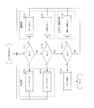
- FIG. 1 shows a manipulator system 1 of the present embodiment.
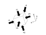
- FIG. 2 shows a triaxial acceleration sensor used as an example of the tap operation detection unit 22 of the present embodiment.
- the manipulator system 1 of the present embodiment includes an operation unit 2 operated by an operator, a manipulator 3 operated by the operation unit 2, and a system control unit 4 that controls the manipulator 3 according to the operation of the operation unit 2. Prepare.
- the operation unit 2 includes a master arm 21 operated by an operator, a tap operation detection unit 22 that detects vibration or movement, and an impact detection unit 23 that detects an impact or the like.
- the manipulator 3 includes a manipulator body 31 and a drive unit 32.
- the master arm 21 has a shape corresponding to the manipulator body 31 and instructs operation of the manipulator body 31 and driving of the drive unit 32.
- the system control unit 4 controls the drive unit 32 so that the manipulator body 31 moves in the same manner as the master arm 21.
- the tap operation detection unit 22 includes a triaxial acceleration sensor that detects triaxial movement or an imaging sensor that detects the presence or absence of vibration by imaging the state of movement. For example, in the case of a three-axis acceleration sensor, vibrations in the ⁇ x direction, the ⁇ y direction, and the ⁇ z direction can be detected as shown in FIG.
- the impact detection unit 23 is disposed at a position corresponding to the elbow of the operator, and detects an input when the operator hits the elbow.
- a uniaxial acceleration sensor or a sensor that detects contact may be used.
- FIG. 3 shows an example of the operation of the operation unit 2 of the manipulator system 1 of the present embodiment.
- FIG. 4 shows another example of the operation of the operation unit 2 of the manipulator system 1 of the present embodiment.
- the operator grips and operates the master arm 21 of the operation unit 2.
- the manipulator body 31 moves in the same manner as the master arm 21.
- the operator taps the master arm 21 to apply vibration to the tap operation detection unit 22, thereby changing the setting of the manipulator body 31, changing the mode, and the like. be able to.
- the tap operation detection unit 22 detects an input from the ⁇ y direction. Further, when the operator taps the master arm 21 with the left hand or the index finger from the front, the input from the ⁇ x direction is detected. Further, when the operator taps the master arm 21 with the thumb or the like from the left side, an input from the + z direction is detected.
- the tap operation detection unit 22 detects an input from the ⁇ z direction. Further, when the operator taps the master arm 21 from below with the middle finger or the like, an input from the + y direction is detected. When the direction is difficult for the operator to tap the master arm 21 as in the + x direction, the impact detection unit 23 shown in FIG. 1 may be assigned to the input in the + x direction.
- setting change or mode conversion of the manipulator body 31 may be performed not only by the direction of the tap operation but also by the strength, number of times, or interval of the tap operation.
- FIG. 5 shows a medical system 10 using the manipulator system 1 of the present embodiment.
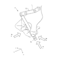
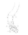
- FIG. 6 shows the configuration of the manipulator 3 at the tip of the overtube 33 of this embodiment.
- the medical system 10 of the present embodiment is preferably a master / slave system.
- the medical system 10 includes an operation unit 2 having a master arm 21, a master input unit 5 for issuing an operation command, and a slave manipulator 6 having a slave arm 61, and allows the operator Op to operate the master arm 21.
- the slave arm 61 and the manipulator 3 are remotely controlled so as to follow.
- the operation command via the master arm 21 is transmitted to the master control unit 41 of the system control unit 4, appropriately converted as necessary, and then input to the slave arm control unit 43 and the manipulator control unit 42. . Thereafter, an operation signal is sent from the manipulator control unit 42 to the slave manipulator 6, and the slave arm 61 and the manipulator 3 operate.
- the electric knife control unit 44 performs control such as output setting of the electric knife
- the display unit control unit 45 performs control such as setting change of the endoscope 31c and the display unit 51.
- These control units may be combined into a single casing, or may be configured by combining existing products.
- the slave manipulator 6 is installed on the operating table 11 on which the patient P is placed.
- the slave arm 61 has a plurality of multi-degree-of-freedom joints and can perform multi-axis operation. Each multi-degree-of-freedom joint is individually driven by a power unit (not shown).
- a power unit for example, a servo motor provided with an incremental encoder, a speed reducer, or the like can be used.
- the manipulator 3 that is inserted into the body of the patient P and performs a procedure is attached to the distal end of the slave arm 61.
- the manipulator 3 includes treatment instruments 31 a and 31 b and an endoscope 31 c and is inserted into the overtube 33.
- the tip of the overtube 33 is inserted into the body of the patient P.
- a plurality of types having different structures and shapes of the treatment portion on the distal end side are prepared, which can be exchanged by attaching / detaching them to / from the distal end portion of the slave arm 61, or It is exchanged by inserting / removing the inside of the channel provided in 33, and various procedures are performed.
- the endoscope 31c acquires an image of a surgical field including a procedure target site where a procedure is performed by the treatment tools 31a and 31b in the body of the patient P.
- the master input unit 5 includes a plurality of master arms 21 operated by the operator Op and a display unit 51 on which an image acquired by the endoscope 31c is displayed.
- Each master arm 21 has a known configuration capable of multi-axis operation, and an operator grasps and issues an operation command to the distal end side close to the operator Op.
- the insertion portion of this embodiment includes a long overtube 33 having flexibility, and treatment instruments 31a and 31b and an endoscope 31c that are inserted into manipulator insertion holes of the overtube 33.
- the treatment tools 31a and 31b and the endoscope 31c have a structure applicable to the manipulator system 1 of the present embodiment.
- the manipulator 3 of the present embodiment has a first treatment tool 31a and a second treatment tool 31b, and as an end effector, the first treatment tool 31a has an electric knife, and the second treatment tool 31b has a gripping portion.
- the distal end side of the manipulator 3 can be protruded from the overtube 33 and is configured by a curved portion in which a plurality of node rings are arranged in the axial direction. Both ends of an operation wire for driving the bending portion are fixed to the most distal node ring, and the bending portion can be bent by driving the operation wire. It is also possible to rotate in the axial direction. Similarly, it is preferable that the overtube 33 itself be rotatable in the curved and axial directions.
- the medical system 10 of the present embodiment can control the slave arm 61, the manipulator 3, and the like by the master arm 21 of the operation unit 2.
- the master arm 21 according to the present embodiment is provided with the tap operation detection unit 22 illustrated in FIG. 1, and when the operator Op taps the master arm 21, the slave arm 61, the manipulator 3, and the first treatment. It is possible to switch to the control mode for controlling the electric knife of the tool 31a, the display unit 51, or the like. For example, when tapping in the + y direction, the mode is switched to a mode for controlling the slave arm 61, and when tapping in the -y direction, the mode for controlling the manipulator 3 is switched. It is preferable that information corresponding to the mode is displayed on the display unit 51.
- the tap operation detection unit 22 may be provided in the slave arm 61 or the like, and may be operated by the second operator Oa.
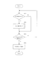
- FIG. 7 shows a tap control flowchart of the medical system of this embodiment.
- step 1 it is determined whether or not it is a tap operation mode (ST1).
- step 1 in the case of the tap operation mode, in step 2, the process proceeds to a tap operation mode subroutine (ST2).
- ST2 The subroutine for the tap operation mode will be described later. If it is determined in step 1 that the mode is not the tap operation mode, the process proceeds to step 3.
- step 3 it is determined whether or not the manipulator system 1 is operating (ST3).
- step 3 when the manipulator system 1 is not in operation, the process returns to step 1. If the manipulator system 1 is operating in step 3, a master-slave operation is performed in step 4 (ST4).
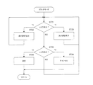
- FIG. 8 shows an example of a control flowchart of the tap operation mode of the medical system of the present embodiment.
- step 2 when the process proceeds to the tap operation mode subroutine, first, in step 11, it is determined whether the tap direction is the ⁇ z direction (ST11). In step 11, if the tap direction is the -z direction, in step 12, a transition is made to a treatment clutch mode for connecting / disconnecting the treatment tool (ST12), and then the process returns to step 11. In step 11, when the tap direction is the + z direction, in step 13, the mode shifts to an observation zoom mode in which the endoscope is zoomed (ST13), and then the process returns to step 11. .
- step 11 if the tap direction is not the ⁇ z direction, it is determined in step 14 whether the tap direction is the ⁇ x direction (ST14). If the tap direction is in the -x direction at step 14, the process proceeds to a scaling mode for treatment for selecting a scaling function for changing the operation ratio of the master arm and the slave arm at step 15 (ST15). Return. In step 14, when the tap direction is the + x direction, in step 16, the mode is shifted to an observation special light mode for selecting illumination light (ST16), and then the process returns to step 11.
- step 17 If it is determined in step 14 that the tap direction is not the ⁇ x direction, it is determined in step 17 whether the tap direction is the ⁇ y direction (ST17). If the tap direction is in the -y direction at step 17, the process proceeds to ablation / incision mode for setting the output for an energy treatment instrument such as an electric knife in step 18 (ST18), and then the process returns to step 11. If the tap direction is the + y direction in step 17, the mode is canceled in step 19 (ST19), and the control flow returns to the control flow shown in FIG. If it is determined in step 17 that the tap direction is not ⁇ y direction, the process returns to step 11.
- each mode of the medical system of the present embodiment illustrated in FIG. 8 is not limited to this example, and other modes may be used.
- FIG. 9 shows an example of a clutch mode control flowchart.
- step 21 it is determined whether the tap direction is the ⁇ x direction (ST21). If the tap direction is the -x direction in step 21, the previous selection item is moved in step 22 (ST22), and then the process returns to step 21. In step 21, when the tap direction is the + x direction, in step 23, the next selection item is moved (ST23), and then the process returns to step 21.
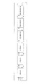
- FIG. 10 shows an example of mode transition in the clutch mode.
- connection / disconnection of the treatment tool and the endoscope can be selected every time the user taps. If the endoscope is selected to be controllable ON at the current stage, when a tap is detected in the + x direction of the master arm 21, the right arm and left arm treatment tools are selected to be controllable ON. Further, when a tap is detected in the ⁇ x direction of the master arm 21, the left arm treatment instrument is selected to be controllable ON.
- step 24 it is determined in step 24 whether the tap direction is the ⁇ y direction (ST24). If the tap direction is the -y direction in step 24, the selected item is determined in step 25 (ST25). Thereafter, the process returns to step 11 shown in FIG. If the tap direction is the + y direction in step 24, the selected item is canceled in step 26 (ST26). Thereafter, the process returns to step 11 shown in FIG.
- control may be performed according to the flow shown in FIG.
- the criteria for determining the tap operation may be different.
- the determination is made based on the direction of the tap operation, but the number or strength of the tap operation may be used.
- the transition in the mode of FIG. 10 may be set in each mode.
- the operation unit 2 operated by the operator the manipulator 3 operated by the operation unit 2, and the system control unit that controls the manipulator 3 according to the operation of the operation unit 2.
- the information detected by the tap operation detection unit 22 includes the direction, strength, or number of tap operations
- the system control unit 4 includes the tap operation detection units 22 and 23. Since the control set for each information is performed according to the information detected by the operator, the control can be easily performed by the tap operation of the operator, and the operability can be improved.
- the operation unit 2 has the master arm 21 that interlocks the manipulator 3, and the tap operation detection unit 22 is provided on the master arm 21, so that the operability is further improved. It becomes possible to make it.
- the system control unit 4 includes the clutch control for connecting and disconnecting the operation of the manipulator 3 according to the information detected by the tap operation detection unit 22, so that the manipulator can be quickly used in an emergency. 3 can be stopped.
- the slave manipulator 6 having the operation unit 2 and including the master input unit 5 for issuing an operation command, the slave arm 61 and the manipulator 3 is provided. Since the slave arm 61 is remotely controlled so as to follow the operation of the master arm 21, more various operations can be realized.
- the second operator Oa can also tap the speed setting at the time of positioning of the slave arm 61, and the installation positioning before the operation and the change of the installation position accompanying the change of the patient position during the operation become easy. .
- the manipulator 3 has treatment tool 31a, 31b and the endoscope 31c
- the master input part 5 is a display which displays the image
- the system controller 4 switches the control of at least the treatment instruments 31a and 31b, the endoscope 31c, and the display unit 51 in accordance with information detected by the tap operation detectors 22 and 23.
- the selection operation can be easily performed by the user's tap operation.
Landscapes
- Engineering & Computer Science (AREA)
- Health & Medical Sciences (AREA)
- Life Sciences & Earth Sciences (AREA)
- Surgery (AREA)
- Robotics (AREA)
- Nuclear Medicine, Radiotherapy & Molecular Imaging (AREA)
- Veterinary Medicine (AREA)
- Biomedical Technology (AREA)
- Heart & Thoracic Surgery (AREA)
- Medical Informatics (AREA)
- Molecular Biology (AREA)
- Animal Behavior & Ethology (AREA)
- General Health & Medical Sciences (AREA)
- Public Health (AREA)
- General Engineering & Computer Science (AREA)
- Theoretical Computer Science (AREA)
- Human Computer Interaction (AREA)
- Physics & Mathematics (AREA)
- General Physics & Mathematics (AREA)
- Pathology (AREA)
- Oral & Maxillofacial Surgery (AREA)
- Mechanical Engineering (AREA)
- Manipulator (AREA)
- Surgical Instruments (AREA)
Abstract
【課題】 小さいスペースで多様な操作を実現可能なマニピュレータシステム及び医療システムを提供する。 【解決手段】 マニピュレータシステム(1)は、操作者が操作する操作部(2)と、操作部(2)によって操作されるマニピュレータ(3)と、操作部(2)の操作に応じてマニピュレータ(3)を制御するシステム制御部(4)と、操作者のタップ操作を検出するタップ操作検出部(22)と、を備え、システム制御部(4)は、タップ操作検出部(22)が検出する情報に応じて制御を切り替えることを特徴とする。
Description
本発明は、外科手術等において患者に挿入され、観察、処置等を行うことのできるマニピュレータシステム及び医療システムに関するものである。
患者の体腔内に処置具を挿入して、処置具先端をワイヤ等で牽引することで、体腔内臓器を観察したり、治療をおこなったりする医療機器が広く用いられている。近年、このような医療機器は、様々な処置を行う必要があるため構造が複雑化及び高度化している。また、構造の複雑化及び高度化に伴い、操作も複雑化及び高度化している。
特許文献1には、ジョイスティック型操作装置、アーム型操作装置、タッチパッド型操作装置、及びフットスイッチ等を用いて、操作性を向上したマニピュレータシステムが記載されている。
しかしながら、操作装置が多くなると、それらを配置するための大きなスペースが必要となり、そのスペースを確保することが困難となっていた。また、例えば、医療行為を行う際には、感染防止等の理由からゴム製の手袋等を着用することになっているが、手袋等を着用した状態で操作装置を操作することは使い勝手が悪かった。
本発明は上記課題に着目してなされたものであり、小さいスペースで多様な操作を実現可能なマニピュレータシステム及び医療システムを提供することにある。
本発明の一実施形態に係るマニピュレータシステムは、
操作者が操作する操作部と、
前記操作部によって操作されるマニピュレータと、
前記操作部の操作に応じて前記マニピュレータを制御するシステム制御部と、
前記操作者のタップ操作を検出するタップ操作検出部と、
を備え、
前記システム制御部は、前記タップ操作検出部が検出する情報に応じて制御を切り替える
ことを特徴とする。
操作者が操作する操作部と、
前記操作部によって操作されるマニピュレータと、
前記操作部の操作に応じて前記マニピュレータを制御するシステム制御部と、
前記操作者のタップ操作を検出するタップ操作検出部と、
を備え、
前記システム制御部は、前記タップ操作検出部が検出する情報に応じて制御を切り替える
ことを特徴とする。
本発明の一実施形態に係るマニピュレータシステムは、
前記タップ操作検出部が検出する情報は、タップ操作の方向、強さ、又は回数を含み、
前記システム制御部は、前記タップ操作検出部が検出する情報に応じて前記情報毎に設定された制御を行う。
前記タップ操作検出部が検出する情報は、タップ操作の方向、強さ、又は回数を含み、
前記システム制御部は、前記タップ操作検出部が検出する情報に応じて前記情報毎に設定された制御を行う。
本発明の一実施形態に係るマニピュレータシステムは、
前記操作部は、前記マニピュレータを連動させるマスターアームを有し、
前記タップ操作検出部は、前記マスターアームに設けられる。
前記操作部は、前記マニピュレータを連動させるマスターアームを有し、
前記タップ操作検出部は、前記マスターアームに設けられる。
本発明の一実施形態に係るマニピュレータシステムは、
前記システム制御部は、前記タップ操作検出部が検出する情報に応じて、前記マニピュレータの作動を断接するクラッチ制御を含む。
前記システム制御部は、前記タップ操作検出部が検出する情報に応じて、前記マニピュレータの作動を断接するクラッチ制御を含む。
本発明の一実施形態に係るマニピュレータシステムを用いた医療システムは、
前記操作部を有し、操作指令を発するためのマスタ入力部と、
スレーブアーム及び前記マニピュレータを含むスレーブマニピュレータと、
を備え、
前記マスターアームの操作に追従させるようにして前記スレーブアームを遠隔制御する
ことを特徴とする。
前記操作部を有し、操作指令を発するためのマスタ入力部と、
スレーブアーム及び前記マニピュレータを含むスレーブマニピュレータと、
を備え、
前記マスターアームの操作に追従させるようにして前記スレーブアームを遠隔制御する
ことを特徴とする。
本発明の一実施形態に係る医療システムは、
前記マニピュレータは、処置具と内視鏡を有し、
前記マスタ入力部は、前記内視鏡が撮像した映像を表示する表示部を有し、
前記システム制御部は、前記タップ操作検出部が検出する情報に応じて、少なくとも前記処置具、前記内視鏡、及び前記表示部の制御を切り替える。
前記マニピュレータは、処置具と内視鏡を有し、
前記マスタ入力部は、前記内視鏡が撮像した映像を表示する表示部を有し、
前記システム制御部は、前記タップ操作検出部が検出する情報に応じて、少なくとも前記処置具、前記内視鏡、及び前記表示部の制御を切り替える。
この態様に係るマニピュレータシステム及び医療システムによれば、小さいスペースで多様な操作を実現することが可能となる。
以下、実施形態について説明する。
図1は、本実施形態のマニピュレータシステム1を示す。図2は、本実施形態のタップ操作検出部22の一例として用いられる3軸加速度センサを示す。
本実施形態のマニピュレータシステム1は、操作者が操作する操作部2と、操作部2によって操作されるマニピュレータ3と、操作部2の操作に応じてマニピュレータ3を制御するシステム制御部4と、を備える。
操作部2は、操作者が操作するマスターアーム21と、振動又は動きを検出するタップ操作検出部22と、衝撃等を検出する衝撃検出部23と、を有する。マニピュレータ3は、マニピュレータ本体31と、駆動部32と、を有する。
マスターアーム21は、マニピュレータ本体31に対応した形状であって、マニピュレータ本体31の操作及び駆動部32の駆動を指示する。操作者がマスターアーム21を動かすことで、マニピュレータ本体31がマスターアーム21と同様の動きをするようにシステム制御部4が駆動部32を制御する。
タップ操作検出部22は、3軸の動きを検出する3軸加速度センサ又は動きの様子を撮像することで振動の有無を検出する撮像センサ等からなる。例えば、3軸加速度センサの場合、図2に示すように、±x方向、±y方向、及び±z方向の振動を検出することが可能である。
衝撃検出部23は、操作者の肘に対応する位置に配置され、操作者が肘で叩くことで入力を検出する。例えば、1軸加速度センサ又は接触したことを検出するセンサ等でよい。
図3は、本実施形態のマニピュレータシステム1の操作部2の操作の一例を示す。図4は、本実施形態のマニピュレータシステム1の操作部2の操作の他の例を示す。
操作者は、操作部2のマスターアーム21を握り操作する。操作者がマスターアーム21を動かすことで、マニピュレータ本体31がマスターアーム21と同様の動きをする。
本実施形態の操作部2では、この操作とは別に、操作者がマスターアーム21をタップすることによってタップ操作検出部22に振動を与えることで、マニピュレータ本体31の設定変更やモード変換等を行うことができる。
タップ操作検出部22は、図3に示すように、操作者がマスターアーム21を上方から人差し指等でタップした場合、-y方向からの入力を検出する。また、操作者がマスターアーム21を左手や人差し指等で正面からタップした場合、-x方向からの入力を検出する。さらに、操作者がマスターアーム21を親指等で左側面からタップした場合、+z方向からの入力を検出する。
同様に、タップ操作検出部22は、図4に示すように、操作者がマスターアーム21を右側面から人差し指等でタップした場合、-z方向からの入力を検出する。また、操作者がマスターアーム21を下方から中指等でタップした場合、+y方向からの入力を検出する。なお、+x方向のように操作者がマスターアーム21をタップすることが難しい方向の場合には、図1に示した衝撃検出部23を+x方向の入力に割り当てればよい。
なお、タップ操作の方向だけでなく、タップ操作の強さ、回数、又は間隔等によって、マニピュレータ本体31の設定変更やモード変換等を行ってもよい。
次に、本実施形態のマニピュレータシステム1を用いた医療システム10について説明する。
図5は、本実施形態のマニピュレータシステム1を用いた医療システム10を示す。図6は、本実施形態のオーバーチューブ33の先端のマニピュレータ3の構成を示す。
本実施形態の医療システム10は、マスタスレーブ方式が好ましい。医療システム10は、操作部2がマスターアーム21を有し、操作指令を発するためのマスタ入力部5と、スレーブアーム61を有するスレーブマニピュレータ6とを備え、操作者Opによるマスターアーム21の操作に追従させるようにしてスレーブアーム61やマニピュレータ3を遠隔制御するものである。マスターアーム21を介した操作指令は、システム制御部4のマスタ制御部41に送信され、必要に応じて適宜変換処理が施された後、スレーブアーム制御部43やマニピュレータ制御部42に入力される。その後、マニピュレータ制御部42からスレーブマニピュレータ6へ動作信号が送られ、スレーブアーム61やマニピュレータ3が動作する。また、電気メス制御部44は電気メスの出力設定などの制御をおこない、表示部制御部45は内視鏡31cや表示部51の設定変更などの制御をおこなう。これらの制御部は一つの筺体にまとめても良いし、既存の製品を組み合わせるなどして構成しても良い。
図5に示すように、スレーブマニピュレータ6は、患者Pが載置される手術台11に設置されている。スレーブアーム61は複数の多自由度関節を有して構成されており、多軸動作可能である。各多自由度関節は、図示しない動力部によって個別に駆動される。動力部としては、例えばインクリメンタルエンコーダや減速器等を備えたサーボモータ等を用いることができる。
スレーブアーム61の先端部には、患者Pの体内に挿入されて手技を行うマニピュレータ3が取り付けられる。図6に示すように、マニピュレータ3は、処置具31a,31bと内視鏡31cを有し、オーバーチューブ33に挿入される。オーバーチューブ33の先端は、患者Pの体内に挿入される。処置具31a,31bは、手技によって使い分けるため、先端側の処置部の構造や形状が異なる複数種類が用意されており、これをスレーブアーム61の先端部に着脱することで交換したり、オーバーチューブ33に設けられたチャンネル内を挿入・抜去することで交換し、各種手技を行う。内視鏡31cは、患者Pの体内で処置具31a,31bによって手技が行われる手技対象部位を含む術野の映像を取得する。
マスタ入力部5は、操作者Opが操作する複数のマスターアーム21と、内視鏡31cにより取得された映像が表示される表示部51とを備えている。各マスターアーム21は、多軸動作可能な公知の構成を有し、操作者Opに近い先端側に、術者が把持して操作指令を発する。
本実施形態の挿入部分は、可撓性を有する長尺のオーバーチューブ33と、オーバーチューブ33のマニピュレータ挿入孔に挿入される処置具31a,31b及び内視鏡31cを有する。なお、処置具31a,31b及び内視鏡31cは、本実施形態のマニピュレータシステム1に適用可能な構造である。
本実施形態のマニピュレータ3は、第1処置具31aと第2処置具31bを有し、エンドエフェクタとして、第1処置具31aは電気メスを有し、第2処置具31bは把持部を有する。マニピュレータ3の先端側は、オーバーチューブ33から突出可能であって、それぞれ複数の節輪を軸線方向に並べて配置された湾曲部で構成される。最も先端側の節輪には、湾曲部を駆動するための操作ワイヤの両端部が固定されており、操作ワイヤを駆動することで湾曲部を湾曲させることができる。また、軸方向に回転させることも可能である。同様に、オーバーチューブ33自体も湾曲及び軸方向に回転可能であることが好ましい。
本実施形態の医療システム10は、操作部2のマスターアーム21によって、スレーブアーム61及びマニピュレータ3等を制御することができる。本実施形態のマスターアーム21には、図1に記載されたタップ操作検出部22が設けられており、操作者Opがマスターアーム21をタップすることによって、スレーブアーム61、マニピュレータ3、第1処置具31aの電気メス、又は表示部51等を制御する制御モードにそれぞれ切り替えることが可能となっている。例えば、+y方向にタップした場合、スレーブアーム61を制御するモード、-y方向にタップした場合、マニピュレータ3を制御するモード等に切り替える。表示部51には、モードに応じた情報が表示されることが好ましい。なお、タップ操作検出部22は、スレーブアーム61等に設けてもよく、第2の操作者Oaが操作してもよい。
図7は、本実施形態の医療システムのタップ制御フローチャートを示す。
まず、ステップ1で、タップ操作モードか否かを判定する(ST1)。
ステップ1において、タップ操作モードの場合、ステップ2で、タップ操作モードのサブルーチンに進む(ST2)。タップ操作モードのサブルーチンについては後述する。ステップ1において、タップ操作モードでない場合、ステップ3に進む。
次に、ステップ3で、マニピュレータシステム1が動作中か否かを判定する(ST3)。ステップ3において、マニピュレータシステム1が動作中でない場合、ステップ1に戻る。ステップ3において、マニピュレータシステム1が動作中である場合、ステップ4で、マスタスレーブ操作を行う(ST4)。
図8は、本実施形態の医療システムのタップ操作モードの制御フローチャートの一例を示す。
図7に示したステップ2において、タップ操作モードのサブルーチンに進むと、まず、ステップ11で、タップの方向が±z方向か否かを判定する(ST11)。ステップ11において、タップの方向が-z方向の場合、ステップ12で、処置具の断接を行う処置用のクラッチモードに移行し(ST12)、その後ステップ11に戻る。ステップ11において、タップの方向が+z方向の場合、ステップ13で、内視鏡のズーム操作を行う観察用のズームモードに移行し(ST13)、その後ステップ11に戻る。。
ステップ11において、タップの方向が±z方向でない場合、ステップ14で、タップの方向が±x方向か否かを判定する(ST14)。ステップ14において、タップの方向が-x方向の場合、ステップ15で、マスターアームとスレーブアームの動作比率を変更するスケーリング機能を選定する処置用のスケーリングモードに移行し(ST15)、その後ステップ11に戻る。ステップ14において、タップの方向が+x方向の場合、ステップ16で、照明光を選定する観察用の特殊光モードに移行し(ST16)、その後ステップ11に戻る。
ステップ14において、タップの方向が±x方向でない場合、ステップ17で、タップの方向が±y方向か否かを判定する(ST17)。ステップ17において、タップの方向が-y方向の場合、ステップ18で、電気メスなどのエナジー処置具用の出力などを設定する焼灼・切開モードに移行し(ST18)、その後ステップ11に戻る。ステップ17において、タップの方向が+y方向の場合、ステップ19で、モード解除し(ST19)、図7に示した制御フローに戻る。ステップ17において、タップの方向が±y方向でない場合、ステップ11に戻る。
なお、図8に示した本実施形態の医療システムの各モードは、この例に限らず、他のモードを用いてもよい。
このように、本実施形態の医療システムでは、タップ操作によって容易に各モードに移行することが可能となる。
次に、モード内での制御について説明する。本実施形態では、一例としてクラッチモードを説明する。
図9は、クラッチモードの制御フローチャートの一例を示す。
クラッチモードでは、まず、ステップ21で、タップの方向が±x方向か否かを判定する(ST21)。ステップ21において、タップの方向が-x方向の場合、ステップ22で、前の選択項目に移動させ(ST22)、その後ステップ21に戻る。ステップ21において、タップの方向が+x方向の場合、ステップ23で、次の選択項目に移動させ(ST23)、その後ステップ21に戻る。
図10は、クラッチモードのモード遷移の一例を示す。
クラッチモードでは、例えば、マスターアーム21を±x方向にタップすることによって断接する部分の選択が順次切り替わる。一例として図10に示すように、タップする毎に処置具及び内視鏡の断接を選択することができる。現段階で内視鏡が制御可能なONに選択されている場合、マスターアーム21の+x方向にタップが検出されると、右腕用と左腕用の処置具が制御可能なONに選択される。また、マスターアーム21の-x方向にタップが検出されると、左腕用の処置具が制御可能なONに選択される。
ステップ21において、タップの方向が±x方向でない場合、ステップ24で、タップの方向が±y方向か否かを判定する(ST24)。
ステップ24において、タップの方向が-y方向の場合、ステップ25で、選択した項目を決定する(ST25)。その後、図8に示したステップ11に戻る。ステップ24において、タップの方向が+y方向の場合、ステップ26で、選択した項目をキャンセルする(ST26)。その後、図8に示したステップ11に戻る。
ステップ24において、タップの方向が-y方向の場合、ステップ25で、選択した項目を決定する(ST25)。その後、図8に示したステップ11に戻る。ステップ24において、タップの方向が+y方向の場合、ステップ26で、選択した項目をキャンセルする(ST26)。その後、図8に示したステップ11に戻る。
なお、他のモードであっても図9に示すようなフローで制御すればよい。その際、タップ操作の判定基準は異なるものであってもよい。例えば、本実施形態では、タップ操作の方向で判定したが、タップ操作の回数又は強さ等であってもよい。また、図10のモード内での遷移は、それぞれのモードで設定すればよい。
このように、本実施形態の医療システムでは、操作者のタップ操作によって容易に各モード内での選択操作を行うことが可能となる。
以上、本実施形態のマニピュレータシステム1によれば、操作者が操作する操作部2と、操作部2によって操作されるマニピュレータ3と、操作部2の操作に応じてマニピュレータ3を制御するシステム制御部4と、操作者のタップ操作を検出するタップ操作検出部22,23と、を備え、システム制御部4は、タップ操作検出部22が検出する情報に応じて制御を切り替えるので、小さいスペースで多様な操作を実現することが可能となる。
また、本実施形態のマニピュレータシステム1によれば、タップ操作検出部22が検出する情報は、タップ操作の方向、強さ、又は回数を含み、システム制御部4は、タップ操作検出部22,23が検出する情報に応じて情報毎に設定された制御を行うので、操作者のタップ操作によって容易に制御を行うことができ、操作性を向上させることが可能となる。
また、本実施形態のマニピュレータシステム1によれば、操作部2は、マニピュレータ3を連動させるマスターアーム21を有し、タップ操作検出部22は、マスターアーム21に設けられるので、より操作性を向上させることが可能となる。
また、本実施形態のマニピュレータシステム1によれば、システム制御部4は、タップ操作検出部22が検出する情報に応じて、マニピュレータ3の作動を断接するクラッチ制御を含むので、緊急時に迅速にマニピュレータ3の作動を止めることが可能となる。
さらに、本実施形態に係るマニピュレータシステム1を用いた医療システム10によれば、操作部2を有し、操作指令を発するためのマスタ入力部5と、スレーブアーム61及びマニピュレータ3を含むスレーブマニピュレータ6と、を備え、マスターアーム21の操作に追従させるようにしてスレーブアーム61を遠隔制御するので、より多様な操作を実現することが可能となる。スレーブアーム61の位置決め時の速度設定などを第2の操作者Oaがタップ操作することも可能であり、手術前の設置位置決めや、手術中の患者体位変換に伴う設置位置変更なども容易となる。
また、本実施形態に係る医療システム10によれば、マニピュレータ3は、処置具31a,31bと内視鏡31cを有し、マスタ入力部5は、内視鏡31cが撮像した映像を表示する表示部51を有し、システム制御部4は、タップ操作検出部22,23が検出する情報に応じて、少なくとも処置具31a,31b、内視鏡31c、及び表示部51の制御を切り替えるので、操作者のタップ操作によって容易に選択操作を行うことが可能となる。
なお、この実施形態によって本発明は限定されるものではない。すなわち、実施形態の説明に当たって、例示のために特定の詳細な内容が多く含まれるが、当業者であれば、これらの詳細な内容に色々なバリエーションや変更を加えても、本発明の範囲を超えないことは理解できよう。従って、本発明の例示的な実施形態は、権利請求された発明に対して、一般性を失わせることなく、また、何ら限定をすることもなく、述べられたものである。
1…マニピュレータシステム
10…医療システム
2…操作部
21…マスターアーム
22…タップ操作検出部
23…衝撃検出部(タップ操作検出部)
3…マニピュレータ
31…マニピュレータ本体
32…駆動部
4…システム制御部
5…マスタ入力部
6…スレーブマニピュレータ
61…スレーブアーム
10…医療システム
2…操作部
21…マスターアーム
22…タップ操作検出部
23…衝撃検出部(タップ操作検出部)
3…マニピュレータ
31…マニピュレータ本体
32…駆動部
4…システム制御部
5…マスタ入力部
6…スレーブマニピュレータ
61…スレーブアーム
Claims (6)
- 操作者が操作する操作部と、
前記操作部によって操作されるマニピュレータと、
前記操作部の操作に応じて前記マニピュレータを制御するシステム制御部と、
前記操作者のタップ操作を検出するタップ操作検出部と、
を備え、
前記システム制御部は、前記タップ操作検出部が検出する情報に応じて制御を切り替える
ことを特徴とするマニピュレータシステム。 - 前記タップ操作検出部が検出する情報は、タップ操作の方向、強さ、又は回数を含み、
前記システム制御部は、前記タップ操作検出部が検出する情報に応じて前記情報毎に設定された制御を行う
請求項1に記載のマニピュレータシステム。 - 前記操作部は、前記マニピュレータを連動させるマスターアームを有し、
前記タップ操作検出部は、前記マスターアームに設けられる
請求項1又は2に記載のマニピュレータシステム。 - 前記システム制御部は、前記タップ操作検出部が検出する情報に応じて、前記マニピュレータの作動を断接するクラッチ制御を含む
請求項1乃至3のいずれか1つに記載のマニピュレータシステム。 - 前記操作部を有し、操作指令を発するためのマスタ入力部と、
スレーブアーム及び前記マニピュレータを含むスレーブマニピュレータと、
を備え、
前記マスターアームの操作に追従させるようにして前記スレーブアームを遠隔制御する
ことを特徴とする請求項1乃至4のいずれか1つに記載のマニピュレータシステムを用いた医療システム。 - 前記マニピュレータは、処置具と内視鏡を有し、
前記マスタ入力部は、前記内視鏡が撮像した映像を表示する表示部を有し、
前記システム制御部は、前記タップ操作検出部が検出する情報に応じて、少なくとも前記処置具、前記内視鏡、及び前記表示部の制御を切り替える
請求項5に記載の医療システム。
Priority Applications (4)
| Application Number | Priority Date | Filing Date | Title |
|---|---|---|---|
| CN201680003237.2A CN107073704A (zh) | 2015-02-25 | 2016-01-22 | 机械手系统和医疗系统 |
| EP16755096.1A EP3263290A4 (en) | 2015-02-25 | 2016-01-22 | Manipulator system and medical system |
| JP2016553036A JP6084344B2 (ja) | 2015-02-25 | 2016-01-22 | マニピュレータシステム及び医療システム |
| US15/590,289 US9974620B2 (en) | 2015-02-25 | 2017-05-09 | Manipulator system, and medical system |
Applications Claiming Priority (2)
| Application Number | Priority Date | Filing Date | Title |
|---|---|---|---|
| JP2015034815 | 2015-02-25 | ||
| JP2015-034815 | 2015-02-25 |
Related Child Applications (1)
| Application Number | Title | Priority Date | Filing Date |
|---|---|---|---|
| US15/590,289 Continuation US9974620B2 (en) | 2015-02-25 | 2017-05-09 | Manipulator system, and medical system |
Publications (1)
| Publication Number | Publication Date |
|---|---|
| WO2016136346A1 true WO2016136346A1 (ja) | 2016-09-01 |
Family
ID=56788336
Family Applications (1)
| Application Number | Title | Priority Date | Filing Date |
|---|---|---|---|
| PCT/JP2016/051894 Ceased WO2016136346A1 (ja) | 2015-02-25 | 2016-01-22 | マニピュレータシステム及び医療システム |
Country Status (5)
| Country | Link |
|---|---|
| US (1) | US9974620B2 (ja) |
| EP (1) | EP3263290A4 (ja) |
| JP (1) | JP6084344B2 (ja) |
| CN (1) | CN107073704A (ja) |
| WO (1) | WO2016136346A1 (ja) |
Families Citing this family (9)
| Publication number | Priority date | Publication date | Assignee | Title |
|---|---|---|---|---|
| KR102020393B1 (ko) * | 2017-08-23 | 2019-09-11 | 한국기계연구원 | 원격 초음파 진단시스템 |
| WO2019222495A1 (en) | 2018-05-18 | 2019-11-21 | Auris Health, Inc. | Controllers for robotically-enabled teleoperated systems |
| US11135030B2 (en) | 2018-06-15 | 2021-10-05 | Verb Surgical Inc. | User interface device having finger clutch |
| CN111374767A (zh) * | 2018-12-27 | 2020-07-07 | 苏州汇控智能技术有限公司 | 医疗内窥镜智能机器人系统及内窥镜的控制方法 |
| EP4125670A4 (en) | 2020-03-27 | 2024-04-17 | Auris Health, Inc. | HAND MANIPULATED INPUT DEVICE FOR ROBOT SYSTEM |
| CN112259192A (zh) * | 2020-10-22 | 2021-01-22 | 华志微创医疗科技(北京)有限公司 | 一种手术操作系统以及控制方法 |
| CN112568998B (zh) * | 2020-12-08 | 2022-08-05 | 北京天使之手机器人科技有限公司 | 一种远程主从交互式医疗系统及方法 |
| CN114788735B (zh) * | 2021-01-25 | 2025-01-03 | 北京天使之手机器人科技有限公司 | 具有主端力反馈的远程交互式超声引导穿刺系统及方法 |
| CN112959327B (zh) * | 2021-03-31 | 2022-07-29 | 上海电气集团股份有限公司 | 机器人运动控制方法、系统、电子设备及存储介质 |
Citations (3)
| Publication number | Priority date | Publication date | Assignee | Title |
|---|---|---|---|---|
| JPH05261691A (ja) * | 1992-03-18 | 1993-10-12 | Fujitsu Ltd | 冗長マニピュレータ制御方式 |
| JP2008228967A (ja) * | 2007-03-20 | 2008-10-02 | Hitachi Ltd | マスタ・スレーブ式マニピュレータシステム |
| JP2014184494A (ja) * | 2013-03-21 | 2014-10-02 | Tsubakimoto Chain Co | マニピュレータ装置 |
Family Cites Families (10)
| Publication number | Priority date | Publication date | Assignee | Title |
|---|---|---|---|---|
| US8398541B2 (en) * | 2006-06-06 | 2013-03-19 | Intuitive Surgical Operations, Inc. | Interactive user interfaces for robotic minimally invasive surgical systems |
| US20070257881A1 (en) * | 2006-05-08 | 2007-11-08 | Marja-Leena Nurmela | Music player and method |
| US9211160B2 (en) * | 2008-01-16 | 2015-12-15 | Luiz Geraldo Pivotto | Remotely controlled catheter insertion system with automatic control system |
| JP5192898B2 (ja) | 2008-04-25 | 2013-05-08 | オリンパスメディカルシステムズ株式会社 | マニピュレータシステム |
| US20100134327A1 (en) * | 2008-11-28 | 2010-06-03 | Dinh Vincent Vinh | Wireless haptic glove for language and information transference |
| US9439736B2 (en) * | 2009-07-22 | 2016-09-13 | St. Jude Medical, Atrial Fibrillation Division, Inc. | System and method for controlling a remote medical device guidance system in three-dimensions using gestures |
| US8521331B2 (en) * | 2009-11-13 | 2013-08-27 | Intuitive Surgical Operations, Inc. | Patient-side surgeon interface for a minimally invasive, teleoperated surgical instrument |
| US8682489B2 (en) | 2009-11-13 | 2014-03-25 | Intuitive Sugical Operations, Inc. | Method and system for hand control of a teleoperated minimally invasive slave surgical instrument |
| US20140267024A1 (en) * | 2013-03-15 | 2014-09-18 | Eric Jeffrey Keller | Computing interface system |
| JP5632040B2 (ja) * | 2013-05-17 | 2014-11-26 | オリンパスイメージング株式会社 | 撮像装置およびそのモード切換え方法 |
-
2016
- 2016-01-22 JP JP2016553036A patent/JP6084344B2/ja not_active Expired - Fee Related
- 2016-01-22 EP EP16755096.1A patent/EP3263290A4/en not_active Withdrawn
- 2016-01-22 WO PCT/JP2016/051894 patent/WO2016136346A1/ja not_active Ceased
- 2016-01-22 CN CN201680003237.2A patent/CN107073704A/zh active Pending
-
2017
- 2017-05-09 US US15/590,289 patent/US9974620B2/en active Active
Patent Citations (3)
| Publication number | Priority date | Publication date | Assignee | Title |
|---|---|---|---|---|
| JPH05261691A (ja) * | 1992-03-18 | 1993-10-12 | Fujitsu Ltd | 冗長マニピュレータ制御方式 |
| JP2008228967A (ja) * | 2007-03-20 | 2008-10-02 | Hitachi Ltd | マスタ・スレーブ式マニピュレータシステム |
| JP2014184494A (ja) * | 2013-03-21 | 2014-10-02 | Tsubakimoto Chain Co | マニピュレータ装置 |
Non-Patent Citations (1)
| Title |
|---|
| See also references of EP3263290A4 * |
Also Published As
| Publication number | Publication date |
|---|---|
| EP3263290A1 (en) | 2018-01-03 |
| JPWO2016136346A1 (ja) | 2017-04-27 |
| EP3263290A4 (en) | 2018-11-21 |
| JP6084344B2 (ja) | 2017-02-22 |
| CN107073704A (zh) | 2017-08-18 |
| US9974620B2 (en) | 2018-05-22 |
| US20170239008A1 (en) | 2017-08-24 |
Similar Documents
| Publication | Publication Date | Title |
|---|---|---|
| JP6084344B2 (ja) | マニピュレータシステム及び医療システム | |
| JP7039497B2 (ja) | 手術用器具を制御するためのシステム及び方法 | |
| EP3025671B1 (en) | Medical system | |
| JP5744455B2 (ja) | マスタ・スレーブ方式マニピュレータの制御装置及びその制御方法 | |
| CN102665590B (zh) | 用于内窥镜辅助机器人的人-机器人共享控制 | |
| EP2550926A1 (en) | Medical manipulator system | |
| CN104470449B (zh) | 医疗用操作装置 | |
| JP5959722B2 (ja) | 処置具交換装置及び医療システム | |
| JPWO2014199413A1 (ja) | 医療用マニピュレータ | |
| US10660720B2 (en) | Surgical-manipulator operating device and surgical-manipulator system | |
| JP6033512B1 (ja) | マニピュレータシステム | |
| JPWO2014156250A1 (ja) | マスタスレーブシステム | |
| WO2015129644A1 (ja) | 手術用マニピュレータシステム | |
| WO2015005072A1 (ja) | 手術支援ロボット | |
| JP2016028652A (ja) | 処置具及び処置具システム | |
| JPWO2020141487A5 (ja) | ||
| KR20200030209A (ko) | 탈부착형 로봇 수술 도구를 이용한 다자유도 복강경 수술 장치 | |
| JP6173089B2 (ja) | 医療用マスタースレーブシステムの制御方法 | |
| KR20140121933A (ko) | 수술 로봇 | |
| JPWO2017109900A1 (ja) | チャネルシース及び医療システム | |
| KR101063281B1 (ko) | 싱글 포트 수술용 어댑터 | |
| US11399910B2 (en) | Medical system |
Legal Events
| Date | Code | Title | Description |
|---|---|---|---|
| ENP | Entry into the national phase |
Ref document number: 2016553036 Country of ref document: JP Kind code of ref document: A |
|
| 121 | Ep: the epo has been informed by wipo that ep was designated in this application |
Ref document number: 16755096 Country of ref document: EP Kind code of ref document: A1 |
|
| NENP | Non-entry into the national phase |
Ref country code: DE |
|
| REEP | Request for entry into the european phase |
Ref document number: 2016755096 Country of ref document: EP |