WO2016136391A1 - Procédé et dispositif de localisation de point de défaut, système de surveillance de système d'alimentation électrique, et système de support de planification des installations - Google Patents
Procédé et dispositif de localisation de point de défaut, système de surveillance de système d'alimentation électrique, et système de support de planification des installations Download PDFInfo
- Publication number
- WO2016136391A1 WO2016136391A1 PCT/JP2016/052847 JP2016052847W WO2016136391A1 WO 2016136391 A1 WO2016136391 A1 WO 2016136391A1 JP 2016052847 W JP2016052847 W JP 2016052847W WO 2016136391 A1 WO2016136391 A1 WO 2016136391A1
- Authority
- WO
- WIPO (PCT)
- Prior art keywords
- accident
- sensor
- impedance
- range
- accident point
- Prior art date
- Legal status (The legal status is an assumption and is not a legal conclusion. Google has not performed a legal analysis and makes no representation as to the accuracy of the status listed.)
- Ceased
Links
Images


Classifications
-
- G—PHYSICS
- G01—MEASURING; TESTING
- G01R—MEASURING ELECTRIC VARIABLES; MEASURING MAGNETIC VARIABLES
- G01R31/00—Arrangements for testing electric properties; Arrangements for locating electric faults; Arrangements for electrical testing characterised by what is being tested not provided for elsewhere
- G01R31/08—Locating faults in cables, transmission lines, or networks
- G01R31/088—Aspects of digital computing
-
- H—ELECTRICITY
- H02—GENERATION; CONVERSION OR DISTRIBUTION OF ELECTRIC POWER
- H02H—EMERGENCY PROTECTIVE CIRCUIT ARRANGEMENTS
- H02H3/00—Emergency protective circuit arrangements for automatic disconnection directly responsive to an undesired change from normal electric working condition with or without subsequent reconnection ; integrated protection
Definitions
- the present invention relates to an accident point locating apparatus and method for estimating an accident point at the time of a grid fault in a power system.
- the present invention also relates to a power system monitoring system that communicates with the accident point locating device and a facility plan support system that supports installation planning of system facilities.
- Patent Document 1 US Pat. No. 4,313,169 (Patent Document 1) as background art in this technical field. This patent states that “a sensor installed at one end of the system measures the current and voltage of the line at the time of the accident, The distance between points is calculated from the measured value and the impedance of the system. ”(See summary).
- Non-Patent Document 1 there is “C37.114-2004 IEEE IEEE Guide for Determining Fault Location Location on AC Transmission and Distribution Lines (Non-Patent Document 1). In this document, the accident location method described in Patent Document 1 is explained.
- Non-Patent Document 1 The principle described in Non-Patent Document 1 will be described by taking the fault point rating of the system shown in FIG. 7 as an example.
- the impedance from the distribution substation 201 of the system to the load 207 is assumed to be ZL.
- the current sensor 210 and the voltage sensor 209 are installed in the bus 203 of the distribution substation 201, and the current Ipre before the occurrence of the accident is measured.
- the current Ig and voltage Vg at the time of occurrence of the ground fault accident of the resistance Rf or the short-circuit accident are measured.
- the distance m from the bus 203 to the accident point 205 can be obtained as (Equation 1) and (Equation 2).
- ⁇ Ig * represents a conjugate complex number of ⁇ Ig
- Im represents an imaginary part of the equation.
- the voltage Vg, current Ig, and Ipre used vary depending on the accident type. In the case of a one-wire ground fault, the phase voltage and phase current of the ground fault phase are used. In the case of 3-wire ground fault, 3-wire short circuit, 2-wire short circuit, and 2-wire ground fault, the line voltage and line current of the line where the accident occurred are used.
- An electric power system monitoring system that implements the accident point location method shown in Patent Document 1 obtains a certain point with the position of the accident point as the distance from the sensor.
- an error in the current sensor 210 and the voltage sensor used for the sensor there is a problem that an error between the accident point obtained by the power system monitoring system and the actual accident point, that is, an orientation error occurs.
- the impedance of the system varies depending on the system state. For example, if the temperature of the transmission / distribution line rises, the resistance per unit increases and the length of the system also increases. There is also a problem that this fluctuation increases the orientation error of the conventional accident location method.
- the orientation error In the power system monitoring system, if the orientation error is large, the time for the maintenance staff to search for the accident point is extended, so the power failure time increases. Further, if the range of the orientation error is not known, the maintenance staff cannot be optimally allocated, and the maintenance cost increases. In addition, installation of a high-precision expensive sensor to reduce the orientation error increases the equipment cost.
- the present invention provides an accident point locating device that estimates an accident point in a power system, a sensor value including a measured voltage value and a current value measured before and after the accident measured by a sensor installed in the power system; , Based on a sensor error representing an error range of the sensor in the measurement of the sensor value, an impedance of the power system, and an impedance fluctuation parameter for determining the fluctuation range of the impedance.
- a fluctuation range calculation means for obtaining a fluctuation range, a combination creation means for creating a combination of the sensor value and a value that can be taken by the impedance based on the fluctuation range obtained by the fluctuation range calculation means, and the above based on the combination
- An accident point locating means for calculating an accident point range indicating a distance from the sensor to the accident point; Characterized in that it obtain.
- the present invention even if there is a sensor error or impedance variation, the existence range of the failure point is known, so that there is an effect that the maintenance staff can accurately estimate the time for searching for the accident point. Therefore, an optimal number of maintenance personnel can be assigned to shorten the search time and reach the target power outage time, thereby reducing maintenance costs.
- the orientation error can be estimated from the sensor selection stage, so a low-cost sensor with the minimum error can be selected to reduce facility costs. It is also possible to do.
- the software configuration of the accident point locator 1 is shown.
- the software configuration of the power system monitoring system is shown.
- the software configuration of the equipment plan support system is shown.
- the hardware configuration of the accident point locating apparatus 1 is shown.
- the hardware configuration of an electric power system monitoring system is shown.
- the software configuration of the equipment plan support system is shown.
- the whole power system is shown.
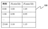
- An impedance table is shown.
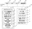
- FIG. 1 is an example of a software configuration diagram of the accident location system 1 according to the present embodiment.
- sensor value 2, sensor error 3, impedance 4, and impedance fluctuation parameter 5 are input values of the accident point locating system 21.
- the accident point range 11 and the determination impossible flag 12 are output values of the accident point locating device 1.
- the sensor value range calculation means 6, the impedance range calculation means 7, the combination generation means 8, the accident point location means 9, and the determination means 10 are the processes of the present invention. First, descriptions of input values and output values are given below.
- the sensor value 2 includes the voltage Vg at the time of the accident measured by the voltage sensor 209 in FIG. 7, the current Ig at the time of the accident, and the current Ipre before the accident. These values are finely stored by the controller 212 at a period of eight times or more of the system frequency, and are copied to the accident location system 21 through communication or a recording medium such as a USB memory.
- the controller 212 needs to detect the occurrence of an accident in order to save the current Ig at the time of the accident and the current Ipre before the accident. This detection is performed based on whether or not the predetermined normal current range is deviated.
- Sensor error 3 is a value obtained by normalizing the difference between the measured value and true value of voltage sensor 209 and current sensor 210 in FIG.
- the impedance 4 is the impedance 4 of the power system from the bus 203 to the load 207 in FIG.
- the impedance variation parameter 5 is temperature or time. Either one is used by the impedance range calculation means 7. In the case of temperature, the bus 203, the transmission / distribution line, or the temperature around them measured by the temperature sensor 211 of FIG. 7 is stored. In the case of time, the value of the timer 103 of the accident point locating apparatus 1 shown in FIG. 5 is used.
- the sensor value range calculation means 6 includes a current minimum value Ipremin before the accident, a current maximum value Ipremax before the accident, a current minimum value Igmin after the accident, a current maximum value Igmax after the accident, a voltage minimum value Vgmin after the accident, The maximum voltage Vgmax after the accident is calculated using (Equation 3) to (Equation 8). However, an error E1 (0 ⁇ E1 ⁇ 1) of the current sensor 210 and an error E2 (0 ⁇ E2 ⁇ 1) of the voltage sensor 209 are assumed.
- the impedance range calculation means 7 calculates the minimum impedance value ZLmin and the maximum impedance value ZLmax.
- the impedance table 109 shown in FIG. 8 is provided inside the impedance range calculation means 7 instead of the function f (t) is also conceivable. Since the temperature of the distribution line depends on the air temperature, and the air temperature changes with time T, the impedance table 109 stores the impedance minimum value ZLmin and the impedance maximum value ZLmax for each time. In the embodiment, it is every hour, but a finer step size (for example, in units of 10 minutes) or a rougher step size (for example, one month) may be used. Finally, the obtained impedance range [ZLmin, ZLmax] is sent to the combination generation means 8.
- a finer step size for example, in units of 10 minutes
- a rougher step size for example, one month
- the combination generation means 8 creates the input parameter combination ⁇ accident current, accident current, accident voltage, impedance ⁇ of the accident point locating means 9.
- the combination generation means 8 has a current range [Igmin, Igmax] at the time of the accident, a current range [Ipremin, Ipremax] before the accident, a voltage range [Vgmin, Vgmax] at the time of the accident, and an impedance range [ZLmin, ZLmax].
- Select one value to create a combination In this embodiment, 16 types of minimum and maximum values are selected. In order to calculate a failure section with higher accuracy, it is possible to cut the closed section into a specified number of sections and create a combination of each value.
- the created combinations of ⁇ current at accident, current before accident, voltage at accident, impedance ⁇ are all sent to the accident location means 9.
- the accident point locating means 9 calculates the distance m from the bus 203 to the accident point according to the accident point algorithm.
- Non-Patent Document 1 many accident point algorithms have been proposed, but any method can be applied in the present invention.
- the present invention employs the method described in Non-Patent Document 1.
- the distance m can be obtained by substituting ⁇ accident current Ig, pre-accident current Ipre, accident voltage Vg, impedance ZL ⁇ into (Equation 1).
- Expression 1 is executed for all combinations obtained by the combination generation means 8, and the obtained total distance m is sent to the determination means 10.
- the determination means 10 obtains the maximum value and the minimum value among m obtained above.
- the maximum value and the minimum value of m are obtained using bubble sort or the like. This is output as the accident point range 11.
- the impedance, the current at the time of accident, the current before the accident, and the voltage at the time of accident may be output when the maximum value and the minimum value of m are reached. If m in the accident point range 11 is m ⁇ 0 or m> 1, there is no failure point on the power distribution system, which is an abnormal value. At this time, any one or more of the impedance, the current at the time of the accident, the current before the accident, and the voltage at the time of the accident may be wrong. Therefore, in order to notify this, the determination impossible flag 12 is output. Further, for debugging, impedance, current at the time of accident, current before accident, and voltage at time of accident may be output.
- FIG. 4 is an example of a hardware configuration diagram of the accident location system 1 according to the present embodiment.
- a CPU 101, a RAM 102, a timer 103, a communication device 104, a program file 107, and a data file 106 constitute a fault location system 21 by a computer connected by a system bus 105.
- the CPU 101 of this computer executes the accident location system 21 of the program file 107.
- the RAM 102 is a memory that temporarily stores the midway calculation result data of the accident point location system 21.
- the program file 107 and the data file 106 are configured by a non-volatile memory such as a flash or a magnetic disk.
- the program file 107 stores the accident location system 21 executed by the CPU 101.
- the accident point location system 21 includes a sensor value range calculation unit 6, an impedance range calculation unit 7, a combination generation unit 8, an accident point location unit 9, and a determination unit 10.
- the data file 106 stores the sensor value 2, the sensor error 3, the impedance 4, and the impedance variation parameter 5, which are inputs of the accident point location system 21. Further, the accident point range 11 and the determination impossible flag 12 which are outputs of the accident point locating system 21 are stored.
- the communication device 104 may be a wired network such as Ethernet (registered trademark), CAN, or LIN, or may be wireless communication such as IEEE802.11a or Zigbee (registered trademark). Select according to the status and cost of public communication network.
- FIG. 7 is an example of a software configuration diagram of the power system monitoring system 13 of the present embodiment.
- a voltage sensor 209, a current sensor 210, and a temperature sensor 211 are input devices of the power system monitoring system 13.
- the monitor 108 is an output device.
- the communication means 14, the accident determination means 15, the accident point location system 21, and the display means 16 are processes of the present invention.
- the accident point location system 21 is the same process as in the first embodiment. First, an explanation of the input device is given below.
- the voltage sensor 209 measures the voltage Vg at the time of the accident.
- the current sensor 210 measures the current Ig at the time of the accident and the current Ipre before the accident.
- the temperature sensor 211 measures any of the bus 203, the power transmission and distribution line, and the ambient temperature. These values are finely stored by the controller 212 at a cycle of eight times or more of the system frequency, and sent to the power system monitoring system 13 through communication.
- the communication means 14 collects information on the voltage Vg at the time of the accident, the current Ig at the time of the accident, the current Ipre before the accident, and the temperature T through communication with the controller 212.
- the controller 212 polls the voltage sensor 209, the current sensor 210, and the temperature sensor 211 at a cycle of eight times or more of the system frequency, and determines that an accident occurs if the current deviates from the specified range. , Update Vg. If the accident is removed, clear Ig and Vg to 0.
- the communication means 14 uses the timer 103 and always polls at a predetermined cycle.
- the controller 212 detects the occurrence of an accident in order to store the current Ig at the time of the accident and the current Ipre before the accident. Therefore, this result may be used. That is, if the current Ig at the time of the accident and the voltage Vg at the time of the accident are not cleared to 0, it can be determined that the accident has occurred. If an accident has occurred, Vg, Ig and Ipre are written to sensor value 2. Further, the temperature T or the current timer 103 is written to the impedance fluctuation parameter 5. Thereafter, the accident location system 21 is activated.
- the accident point location system 21 outputs the accident point range 11 and the determination impossible flag 12 in the same process as in the first embodiment.
- the display means 16 displays the accident point range 11 and the determination impossible flag 12 on the monitor 108.
- the accident point range 11 may display a numerical value range of m, may be illustrated in a system diagram shown in FIG. 7, or may be illustrated on a map.
- FIG. 5 is an example of a hardware configuration diagram of the power system monitoring system 13 of the present embodiment.
- FIG. 5 is substantially the same as FIG. 4 of the first embodiment, except that the monitor 108 is connected to the system bus 105, the communication means 14, the accident determination means 15, and the display means 16 are stored in the program file 107. Is different.
- the communication means 14 can communicate with the controller 212 connected to the network through the communication device 104.
- the display unit 16 can display characters and images on the monitor 108.
- the equipment plan support system 17 uses the offline information such as the logs of the voltage sensor 209 and the current sensor 210 to obtain the accuracy of the future power flow and the accident location at the time of the accident by simulation, and supports the equipment investment plan. It is.
- FIG. 3 is an example of a software configuration diagram of the facility planning system of this embodiment.
- sensor performance data 18 and user created data 19 are inputs to the facility plan support system 17.
- the monitor 108 is an output device.
- the parameter generation means 20, the accident point location system 21, and the display means 16 are processes of the present invention.
- the accident point location system 21 is the same process as in the first embodiment. First, an explanation of the input device will be given below.
- the sensor performance data 18 is a log of the voltage sensor 209, the current sensor 210, and the temperature sensor 211. In order to evaluate the accuracy of accident location, use the log at the time of the accident. Specifically, the voltage and current of each phase at the time of one-wire ground fault, two-wire short circuit, two-wire ground fault, three-wire ground fault, and three-wire short circuit are provided in chronological order. The time increment is at least 8 times the system frequency.
- the user-created data 19 is also time-series data of voltage, current, and temperature of each phase at the time of the accident, similarly to the sensor performance data 18. The user-created data 19 is data created by the user in order to evaluate the accuracy of accident point location for voltage fluctuations and current fluctuations that could not be logged.
- the parameter generation unit 20 scans the sensor performance data 18 and determines whether or not the current deviates from the specified range. If there is a deviating current, it is determined that an accident has occurred, and the data is extracted as the voltage Vg at the time of the accident, the current Ig at the time of the accident, and the temperature T. Further, the current immediately before the data is extracted as the current Ipre before the accident. Then, Vg, Ig, and Ipre are written to sensor value 2. Further, the temperature T or time is written in the impedance fluctuation parameter 5. Thereafter, the accident location system 21 is activated.
- FIG. 6 is an example of a hardware configuration diagram of the facility planning support system 17 of the present embodiment.
- FIG. 6 is substantially the same as FIG. 4 of the first embodiment except that the monitor 108 is connected to the system bus 105 and that the sensor value generation unit and display unit 16 are stored in the program file 107. .
- the display means 16 can display characters and images on the monitor 108.
Landscapes
- Physics & Mathematics (AREA)
- Engineering & Computer Science (AREA)
- Mathematical Physics (AREA)
- Theoretical Computer Science (AREA)
- General Physics & Mathematics (AREA)
- Locating Faults (AREA)
- Emergency Protection Circuit Devices (AREA)
Abstract
L'invention concerne un système de surveillance d'un système d'alimentation électrique dans lequel un dispositif de localisation de point de défaut classique a été mis en œuvre pour obtenir un emplacement de point de défaut sous la forme d'un seul point, sous la forme de distances par rapport aux capteurs. Cependant, il y a des erreurs dans les capteurs de courant électrique et les capteurs de tension que l'on utilise pour de tels capteurs, et il existe ainsi un problème en ce que des erreurs se produisent entre le point de défaut obtenu par le système de surveillance du système d'alimentation électrique et le point de défaut réel, en d'autres termes, une erreur de localisation se produit. En outre, l'impédance du système varie en fonction de l'état du système. Cette variation est également un problème en ce qu'elle donne lieu à une amplification de l'erreur de localisation dans un système de localisation de point de défaut classique. En vue de résoudre ces problèmes, la présente invention concerne un dispositif de localisation de point de défaut qui estime un point de défaut dans un système d'alimentation électrique, caractérisé en ce qu'il comporte : un moyen de calcul de plage de variations qui obtient une plage de variations des valeurs des capteurs et une plage de variation d'une impédance du système d'alimentation électrique, en fonction des valeurs des capteurs, qui comprennent des valeurs de tension mesurées et des valeurs de courant mesurées avant et après le défaut et qui sont mesurées en utilisant des capteurs installés dans le système d'alimentation électrique, des erreurs des capteurs représentant des plages d'erreurs des capteurs par rapport aux mesures des valeurs de capteurs, ladite impédance, et un paramètre de variation d'impédance pour déterminer la plage de variation de l'impédance ; un moyen de création de combinaison qui crée des combinaisons de valeurs que les valeurs des capteurs et la valeur d'impédance peuvent atteindre, en fonction des plages de variations obtenues par le moyen de calcul de plages de variations ; et un moyen de localisation de point de défaut qui calcule une plage de points de défaut représentant les distances des capteurs jusqu'au point de défaut, en fonction des combinaisons.
Priority Applications (2)
| Application Number | Priority Date | Filing Date | Title |
|---|---|---|---|
| EP16755141.5A EP3264114A4 (fr) | 2015-02-27 | 2016-02-01 | Procédé et dispositif de localisation de point de défaut, système de surveillance de système d'alimentation électrique, et système de support de planification des installations |
| US15/537,898 US20180011136A1 (en) | 2015-02-27 | 2016-02-01 | Fault point locating device and method, electric power system monitoring system, and facility planning support system |
Applications Claiming Priority (2)
| Application Number | Priority Date | Filing Date | Title |
|---|---|---|---|
| JP2015037620A JP2016161302A (ja) | 2015-02-27 | 2015-02-27 | 事故点標定装置及び方法、電力系統監視システム、設備計画支援システム |
| JP2015-037620 | 2015-02-27 |
Publications (1)
| Publication Number | Publication Date |
|---|---|
| WO2016136391A1 true WO2016136391A1 (fr) | 2016-09-01 |
Family
ID=56788232
Family Applications (1)
| Application Number | Title | Priority Date | Filing Date |
|---|---|---|---|
| PCT/JP2016/052847 Ceased WO2016136391A1 (fr) | 2015-02-27 | 2016-02-01 | Procédé et dispositif de localisation de point de défaut, système de surveillance de système d'alimentation électrique, et système de support de planification des installations |
Country Status (4)
| Country | Link |
|---|---|
| US (1) | US20180011136A1 (fr) |
| EP (1) | EP3264114A4 (fr) |
| JP (1) | JP2016161302A (fr) |
| WO (1) | WO2016136391A1 (fr) |
Cited By (1)
| Publication number | Priority date | Publication date | Assignee | Title |
|---|---|---|---|---|
| CN109741208A (zh) * | 2018-12-14 | 2019-05-10 | 广州供电局有限公司 | 大面积停电事故应急抢修方案确定方法和装置 |
Families Citing this family (6)
| Publication number | Priority date | Publication date | Assignee | Title |
|---|---|---|---|---|
| US11289942B2 (en) * | 2017-10-27 | 2022-03-29 | Operation Technology Incorporated | Model driven estimation of faulted area in electric distribution systems |
| CN113433417B (zh) * | 2021-05-08 | 2022-06-14 | 湖南大学 | 一种基于量测电压差值的配电网故障定位方法和系统 |
| CN115524574B (zh) * | 2021-06-25 | 2025-12-09 | 南京南瑞继保电气有限公司 | 故障点距离测量方法及装置 |
| CN113640618B (zh) * | 2021-08-06 | 2024-04-26 | 福建中电合创电力科技有限公司 | 一种配电站房监控方法及终端 |
| CN117741333B (zh) * | 2023-11-23 | 2024-09-27 | 国网冀北电力有限公司智能配电网中心 | 基于大数据驱动的配电网故障感知系统 |
| CN118473086B (zh) * | 2024-04-25 | 2025-03-04 | 镇江默勒电器有限公司 | 基于物联网的低压配电故障自动监测方法及系统 |
Citations (4)
| Publication number | Priority date | Publication date | Assignee | Title |
|---|---|---|---|---|
| JPH04134274A (ja) * | 1990-09-27 | 1992-05-08 | Fuji Electric Co Ltd | 多分岐ケーブルの事故点標定方法 |
| JPH0674996A (ja) * | 1992-06-30 | 1994-03-18 | Toshiba Corp | 事故点標定装置 |
| JPH0815006A (ja) * | 1994-06-30 | 1996-01-19 | Matsushita Electric Ind Co Ltd | 音場測定装置 |
| JPH0926453A (ja) * | 1995-07-11 | 1997-01-28 | F M T:Kk | 事故時波形記録方法及びその装置 |
Family Cites Families (10)
| Publication number | Priority date | Publication date | Assignee | Title |
|---|---|---|---|---|
| US7529069B1 (en) * | 2002-08-08 | 2009-05-05 | Weems Ii Warren A | Apparatus and method for ground fault detection and location in electrical systems |
| KR100709616B1 (ko) * | 2005-11-15 | 2007-04-19 | 최면송 | 분포정수 회로 해석을 이용한 지중 케이블 계통의 1선 지락고장점 표정 방법 |
| EP2171488B1 (fr) * | 2007-07-24 | 2010-11-24 | Siemens Aktiengesellschaft | Procédé de localisation d'un défaut à la terre selon le principe de la protection de distance et appareil de protection de distance électrique |
| CN102177440B (zh) * | 2008-10-27 | 2013-11-06 | 西门子公司 | 根据远程保护原理的供电网络中的故障定位 |
| CN101858948B (zh) * | 2009-04-10 | 2015-01-28 | 阿海珐输配电英国有限公司 | 用于在三相中压配电系统中进行暂态和间歇性接地故障检测和方向确定的方法和系统 |
| US8525522B2 (en) * | 2010-04-21 | 2013-09-03 | Schweitzer Engineering Laboratories Inc | Fault location in electric power delivery systems |
| WO2012049294A1 (fr) * | 2010-10-14 | 2012-04-19 | Abb Research Ltd | Dispositif indicateur de paramètre de direction de défaut utilisant uniquement le courant et procédés connexes |
| US8861155B2 (en) * | 2011-08-25 | 2014-10-14 | Southern States, Llc | High-impedance fault detection and isolation system |
| DE102012006332A1 (de) * | 2012-02-06 | 2013-08-08 | Hagenuk KMT Kabelmeßtechnik GmbH | Verfahren zum Verorten eines Kabelfehlers in einem Prüfkabel und zugehörige Vorrichtung |
| FR2989235B1 (fr) * | 2012-04-06 | 2014-03-14 | Schneider Electric Ind Sas | Systeme de controle d'isolement pour reseau electrique securise |
-
2015
- 2015-02-27 JP JP2015037620A patent/JP2016161302A/ja active Pending
-
2016
- 2016-02-01 EP EP16755141.5A patent/EP3264114A4/fr not_active Withdrawn
- 2016-02-01 WO PCT/JP2016/052847 patent/WO2016136391A1/fr not_active Ceased
- 2016-02-01 US US15/537,898 patent/US20180011136A1/en not_active Abandoned
Patent Citations (4)
| Publication number | Priority date | Publication date | Assignee | Title |
|---|---|---|---|---|
| JPH04134274A (ja) * | 1990-09-27 | 1992-05-08 | Fuji Electric Co Ltd | 多分岐ケーブルの事故点標定方法 |
| JPH0674996A (ja) * | 1992-06-30 | 1994-03-18 | Toshiba Corp | 事故点標定装置 |
| JPH0815006A (ja) * | 1994-06-30 | 1996-01-19 | Matsushita Electric Ind Co Ltd | 音場測定装置 |
| JPH0926453A (ja) * | 1995-07-11 | 1997-01-28 | F M T:Kk | 事故時波形記録方法及びその装置 |
Non-Patent Citations (2)
| Title |
|---|
| C37.114-2004 - IEEE GUIDE FOR DETERMINING FAULT LOCATION ON AC TRANSMISSION AND DISTRIBUTION LINES, pages 8 - 9 * |
| See also references of EP3264114A4 * |
Cited By (2)
| Publication number | Priority date | Publication date | Assignee | Title |
|---|---|---|---|---|
| CN109741208A (zh) * | 2018-12-14 | 2019-05-10 | 广州供电局有限公司 | 大面积停电事故应急抢修方案确定方法和装置 |
| CN109741208B (zh) * | 2018-12-14 | 2021-08-10 | 广东电网有限责任公司广州供电局 | 大面积停电事故应急抢修方案确定方法和装置 |
Also Published As
| Publication number | Publication date |
|---|---|
| EP3264114A1 (fr) | 2018-01-03 |
| US20180011136A1 (en) | 2018-01-11 |
| EP3264114A4 (fr) | 2018-12-05 |
| JP2016161302A (ja) | 2016-09-05 |
Similar Documents
| Publication | Publication Date | Title |
|---|---|---|
| WO2016136391A1 (fr) | Procédé et dispositif de localisation de point de défaut, système de surveillance de système d'alimentation électrique, et système de support de planification des installations | |
| US20260029454A1 (en) | Method and system for dynamic fault detection in an electric grid | |
| Soltani et al. | Simultaneous robust state estimation, topology error processing, and outage detection for unbalanced distribution systems | |
| JP6301791B2 (ja) | 配電網の故障予兆診断システムおよびその方法 | |
| US9874593B2 (en) | Decision support system for outage management and automated crew dispatch | |
| EP2866190A1 (fr) | Systèmes et procédés pour détecter, corriger et valider les données défectueuses dans des flux de données | |
| EP2806572A1 (fr) | Détection et localisation des pannes d'alimentation électrique par l'intermédiaire de mappage de grille basse tension | |
| US11657148B2 (en) | Event analysis in an electric power system | |
| US20170278200A1 (en) | System stability monitoring device and system stability monitoring system | |
| JP6164311B1 (ja) | 情報処理装置、情報処理方法、及び、プログラム | |
| CN108957385B (zh) | 一种电能计量设备自动化检定线异常表位确认方法及装置 | |
| US11042134B2 (en) | Power system status estimation device and status estimation method | |
| JP2020530754A (ja) | 下流イベントおよび測定値に基づいた送電網アセットの順位付け | |
| EP3531526A1 (fr) | Estimation de paramètres de réseau électrique | |
| CN114814645B (zh) | 一种电容式电压互感器在线分析方法及相关装置 | |
| JP6116428B2 (ja) | 電力系統監視制御装置およびその制御方法 | |
| CN106600168A (zh) | 一种电网责任区信息校验方法、装置及系统 | |
| CN117152925A (zh) | 基于大数据的电力通信数据处理系统 | |
| US11513148B2 (en) | Method, system and software product to identify installations likely to exhibit an electrical non-conformity | |
| CN118353160B (zh) | 一种无源无线智能型变电站避雷器在线监测多模组系统 | |
| CN119492949B (zh) | 一种电网的故障监测方法、设备及存储介质 | |
| KR101674402B1 (ko) | 손실전력측정 알고리즘 및 이를 이용한 손실전력 측정장치 | |
| EP3025204A1 (fr) | Procédé et système de surveillance d'état | |
| KR101715778B1 (ko) | 시간차 동기 알고리즘 기반 송배전 계통 손실전력 측정 방법 | |
| CN114861745A (zh) | 异常数据的检测方法及系统 |
Legal Events
| Date | Code | Title | Description |
|---|---|---|---|
| 121 | Ep: the epo has been informed by wipo that ep was designated in this application |
Ref document number: 16755141 Country of ref document: EP Kind code of ref document: A1 |
|
| WWE | Wipo information: entry into national phase |
Ref document number: 15537898 Country of ref document: US |
|
| REEP | Request for entry into the european phase |
Ref document number: 2016755141 Country of ref document: EP |
|
| NENP | Non-entry into the national phase |
Ref country code: DE |