WO2016136632A1 - 打込機 - Google Patents
打込機 Download PDFInfo
- Publication number
- WO2016136632A1 WO2016136632A1 PCT/JP2016/054905 JP2016054905W WO2016136632A1 WO 2016136632 A1 WO2016136632 A1 WO 2016136632A1 JP 2016054905 W JP2016054905 W JP 2016054905W WO 2016136632 A1 WO2016136632 A1 WO 2016136632A1
- Authority
- WO
- WIPO (PCT)
- Prior art keywords
- cylinder
- pressure
- piston
- driving machine
- air
- Prior art date
- Legal status (The legal status is an assumption and is not a legal conclusion. Google has not performed a legal analysis and makes no representation as to the accuracy of the status listed.)
- Ceased
Links
Images


Classifications
-
- B—PERFORMING OPERATIONS; TRANSPORTING
- B25—HAND TOOLS; PORTABLE POWER-DRIVEN TOOLS; MANIPULATORS
- B25C—HAND-HELD NAILING OR STAPLING TOOLS; MANUALLY OPERATED PORTABLE STAPLING TOOLS
- B25C1/00—Hand-held nailing tools; Nail feeding devices
- B25C1/04—Hand-held nailing tools; Nail feeding devices operated by fluid pressure, e.g. by air pressure
- B25C1/047—Mechanical details
-
- B—PERFORMING OPERATIONS; TRANSPORTING
- B25—HAND TOOLS; PORTABLE POWER-DRIVEN TOOLS; MANIPULATORS
- B25C—HAND-HELD NAILING OR STAPLING TOOLS; MANUALLY OPERATED PORTABLE STAPLING TOOLS
- B25C1/00—Hand-held nailing tools; Nail feeding devices
- B25C1/06—Hand-held nailing tools; Nail feeding devices operated by electric power
Definitions
- the present invention relates to a driving machine that moves a driver blade with a pressure of a gas such as air to hit a stopper.
- the driving machine described in Patent Document 1 includes a motor provided in a housing, a gear for transmitting the rotational force of the motor to a cam, a cylinder provided in the housing, and a piston accommodated in the cylinder so as to be reciprocally movable.
- a driver blade fixed to the piston, and a bellows provided in the cylinder. The bellows is extendable, the first end of the bellows is connected to the piston, and the second end of the bellows is fixed to the housing. Compressed air is enclosed in the bellows to form a pressure chamber (pneumatic chamber).
- Patent Document 1 Since the driving machine described in Patent Document 1 always encloses air in a pressure chamber formed in the bellows, it is necessary to seal the bellows even when the stopper is not hit. In the bellows, the internal air may gradually decrease as the number of uses and the use period become longer, and the impact force may be reduced.
- the present invention provides a housing, a cylinder provided in the housing, a pneumatic chamber spatially connected to the cylinder, and a piston provided in the cylinder so as to be capable of reciprocating.
- the motor is used to pressurize the pneumatic chamber from a state where the air chamber communicates with the outside, and the motor causes the piston to move from bottom dead center to top dead center in the cylinder. After moving to, it is configured to have a striking mode in which the stopper is driven by moving from the top dead center toward the bottom dead center.
- the operator can easily pressurize the gas pressure in the pneumatic chamber, a long-life and high-performance driving machine can be obtained without suffering from the pressure drop in the pneumatic chamber due to long-term use. realizable. Further, since the pressure in the pneumatic chamber can be reduced, the maintainability when the nail is clogged is greatly improved.
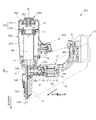
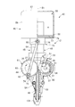
- FIG. 1 is a longitudinal sectional view showing a driving machine 201 according to a first embodiment of the present invention. It is an arrow view seen from the A direction of FIG. 1 (when the piston 47 is a bottom dead center). It is an arrow view seen from the A direction of FIG. 1 (when the piston 47 is a top dead center).
- FIG. 2 is an arrow view of a nose portion 254 viewed from the side opposite to the direction A in FIG. 1.
- 2 is a block circuit diagram of a driving machine 201.
- FIG. FIG. 2 is a partially enlarged view of the vicinity of an outside air intake valve 260 provided in the pressure accumulating container 250 of FIG. It is the elements on larger scale near the external air intake valve 260 provided in the pressure accumulation container 250 of FIG. 1 (the 2).
- FIG. 1 is a longitudinal sectional view showing a driving machine 201 according to a first embodiment of the present invention. It is an arrow view seen from the A direction of FIG. 1 (when the piston 47 is a bottom dead center).
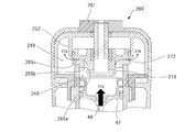
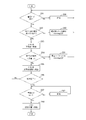
- FIG. 6 is a partial enlarged view of the vicinity of an outside air intake valve 260 provided in the pressure accumulating vessel 250 of FIG. 1 (No. 3). It is a flowchart which shows the pressurization procedure of the pneumatic chamber 249 in the pressure accumulation mode which concerns on the Example of this invention. It is a longitudinal cross-sectional view which shows the driving machine 301 which concerns on the 2nd Example of this invention.
- FIG. 11 is an enlarged longitudinal sectional view of a leak valve 360 in FIG. 10. It is a fragmentary longitudinal cross-section which shows the driving machine which concerns on the modification of the 2nd Example of this invention. It is a front view which shows the driving machine 10 which concerns on the 3rd Example of this invention. It is side surface sectional drawing of the driving machine 10 shown in FIG.
- FIG. 13 It is front sectional drawing of the driving machine 10 shown in FIG. 13 (the 1). It is front sectional drawing of the driving machine 10 shown in FIG. 13 (the 2). It is side surface sectional drawing which shows the 4th Example of the driving machine of this invention. It is front sectional drawing of the driving machine shown in FIG. It is front sectional drawing which shows the 5th Example of the driving machine of this invention. It is side surface sectional drawing of the driving machine shown in FIG.
- the driving machine 201 includes a hitting mechanism (including a cylinder 245, a pressure accumulating vessel 250, a piston 47, and a blade 48) that hits the nail 11 to be driven, an electric motor 13 that generates power for driving the hitting mechanism, A power transmission mechanism that moves the blade 48 of the striking mechanism by the power of the electric motor 13, a storage battery 15 that supplies power to the electric motor 13, and a plurality of nails 11 that are ejected while one nail 11 is fed to the ejection path of the striking mechanism.
- a magazine 16 for holding the nail 11 is provided.
- the nail 11 is a stopper having a narrow round bar or square bar with a sharp tip and a wide rear end in a flange shape. A nail of about 50 to 110 mm can be hit by the driving machine 201.
- the striking mechanism is made of synthetic resin and accommodated in the cylindrical main body housing 202.
- a grip 203 is provided for an operator to hold with one hand, and a mounting portion 204 for the storage battery 15 is provided at the end of the grip 203.
- the storage battery 15 can be attached to and detached from the mounting portion 204.
- the mounting portion 204 accommodates a control circuit board 81 for mounting a controller (control portion) described later.
- a seal member 55 is attached to the outer peripheral surface of the piston 47, and can reciprocate in the axial direction along the center line B1 within the cylinder 245.
- An elongated blade 48 is fixed in the lower portion of the piston 47 in order to drive the nail 11 in the axial direction, and a pressure accumulating container 250 for storing air is provided in the upper portion of the space in which the piston 47 moves.
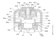
- the pressure accumulating container 250 is formed by a substantially cup-shaped container main body 251 with the opening facing downward, and a flange portion 255 that closes the opening of the container main body 251 and is formed with a mounting portion to the cylindrical cylinder 245. .
- the internal space (pneumatic chamber 249) of the pressure accumulating container 250 has a pneumatic chamber 249 that maintains the air taken in from outside in a pressurized state, and is a space in which air is compressed by the piston 47 (described later in FIG. 2). It is fluidly connected to the cylinder chamber 248).
- an outside air intake valve 260 is provided on the upper portion of the pressure accumulating vessel 250. Details of the outside air intake valve 260 will be described later.
- the storage battery 15 has a storage case and a plurality of battery cells (not shown) stored in the storage case.
- the battery cell is a DC secondary battery that can be charged and discharged, and a lithium ion battery, a nickel hydrogen battery, a lithium ion polymer battery, a nickel cadmium battery, or the like can be used as the battery cell.
- a part of the mounting portion 204 is connected to the motor housing 17 continuing to the casing 233.
- the main body housing 202, the grip 203, the mounting portion 204, the casing 233, and the motor housing 17 are manufactured by a molded product made of a synthetic resin such as plastic, and the nose portion 254 is manufactured by an aluminum alloy or an iron-based metal.
- the component constitutes a casing portion (broadly defined housing) of the driving machine 201.
- the electric motor 13 is a brushless DC motor, and includes a stator 18 that is fixed to the motor housing 17 so as not to rotate, and a rotor 19 that is rotatably supported on the inner peripheral side of the stator 18.
- the stator 18 is obtained by winding a coil 21 for energization around a stator core made of a laminated iron core.
- the rotor 19 includes an output shaft 24 supported by two bearings 82a and 82b, a rotor core fixed to the output shaft 24, and a permanent magnet.
- the output shaft 24 is rotatable about the axis A1.
- a substantially annular inverter circuit board 83 is provided on the end side of the electric motor 13, and a plurality of switching elements 84 such as FETs (Field Effect Transistors) and IGBTs (Insulated Gate Bipolar Transistors) forming an inverter circuit described later. Is installed.
- the inverter circuit board 83 is provided with a magnetic detection element (not shown) such as a Hall IC for detecting the rotational position of the rotor 19.
- the rotational force of the electric motor 13 is transmitted to the drive shaft 234 via the speed reducer 27.
- a known speed reduction mechanism can be used as the speed reducer 27, but here, the planetary gear mechanism is provided in two stages in series to reduce the rotational speed of the output shaft 24 to about one-tenth and to drive the drive shaft 234. Rotate.
- a rotating body 238 is fixed to the end of the drive shaft 234 and rotates in synchronization with the drive shaft 234.
- the rotating body 238 constitutes a part of a power transmission mechanism that moves the blade 48 of the striking mechanism by the power of the electric motor 13, and the configuration and operation thereof will be described later with reference to FIGS.
- the nose portion 254 is attached to the injection direction side of the main body housing 202 and forms an injection path for the nail 11 to be injected.
- the nose portion 254 is provided with a push rod 104 so as to cover the tip portion thereof.
- the push rod 104 is a kind of safety device that is movable in a predetermined range in the same direction as the injection direction and in the opposite direction with respect to the nose portion 254, and is used when performing a driving operation.
- the driving machine 201 is electrically driven even when the trigger (trigger lever) 72 is pulled unless the operator presses the push rod 104 against the object (target material to be driven) of the nail 11 when the nail 11 is driven. Control is performed so that the motor 13 does not rotate.
- the push rod 104 is biased by the compression spring 105 when the tip end side in the injection direction is not in contact with anything, and is located on the injection direction side.
- the push rod 104 moves in the reflecting direction and stops against the force of the compression spring 105.
- a pressing detection switch (not shown) is turned on, and the output is transmitted to a controller described later.
- the controller allows the electric motor 13 to start only when both the state where the push rod 104 is pushed and the state where the trigger 72 is pulled are satisfied.
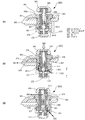
- FIG. 2 is an arrow view seen from the direction A in FIG. 1 and shows a state when the piston 47 is at the bottom dead center.
- This moving mechanism is mainly composed of a rotating body 238 that rotates by the driving force of the electric motor 13 and a blade 48 having a rack 53.
- the rotating body 238 having a pinion (gear) 241 at a part of the outer peripheral edge is rotated, and the pinion 241 is engaged with the rack 53 formed on the longitudinal side surface of the blade 48, whereby the piston 47 is bottom dead centered.
- the rotating body 238 and the pinion 241 are formed as a single piece of metal, and the rotating body 238 can be rotated in the direction of the arrow 242 or in the opposite direction by the rotation of the drive shaft 234.
- the pinion 241 is disposed at the outer edge portion of the rotating body 238 by a rotation angle of about 270 degrees. Accordingly, when the rotating body 238 rotates, the tip teeth 241a of the pinion 241 start to engage with the upper end teeth 53a of the rack 53, so that the blade 48 can be moved upward, thereby being fixed to the blade 48.
- the piston 47 can also be moved toward the top dead center.
- FIG. 3 is a view showing a state where the rotating body 238 is rotated about 300 degrees from the state of FIG. 2 in the direction of the arrow 242, and the meshing of the rack 53 and all the pinions 241 is completed and the lower end teeth 53 b of the rack 53 and the pinions 241 are shown. A state immediately before the rear end teeth 241b are disengaged is shown. When the tip 48 b of the blade 48 moves upward in the injection path 256, the nail 11 to be driven next from the magazine 16 is fed into the injection path 256. Immediately after the state of FIG.
- FIG 4 is an arrow view of the nose portion 254 after the driving of the nail 11 is completed, as viewed from the side opposite to the direction A in FIG.
- the drive shaft 234 continues to rotate because the electric motor 13 is rotating.
- a cylindrical pin 235 provided in parallel with the drive shaft 234 is provided at one place in the circumferential direction of the rotating body 238, and the pin 235 acts on the off switch 236 at the timing when the nail 11 is driven.
- the off switch 236 is provided on the side surface of the nose portion 254, and its output is connected to the controller and transmits an output pulse at the timing when the nail 11 is ejected. In the vicinity of the off switch 236, an operation lever 237 for operating the plunger 236a is provided.
- the operation lever 237 is made of a thin metal plate having elasticity such as a spring material, and has a semi-cylindrical bent portion at the tip.
- the pin 235 provided in parallel with the drive shaft 234 comes into contact with the semi-cylindrical portion of the operation lever 237, and the operation lever 237 is pushed by the pin 235 and deformed to turn off.
- the plunger 236a of the switch 236 is pushed.
- the controller which will be described later, stops supplying drive power to the electric motor 13 when receiving the output signal of the off switch 236. After the plunger 236a is pushed, the contact state between the operation lever 237 and the pin 235 is released, so that the drive shaft 234 is also stopped and the rotating body 238 is stopped at the position shown in FIG. Note that when the nail 11 is driven, the rack 53 and the pinion 241 are in a non-contact state.
- the magnetic sensor 257 is attached to the nose portion 254, and is provided at a position between the lower end tooth 53b of the rack 53 and the adjacent tooth when the piston 47 moves to the bottom dead center.
- the magnetic sensor 257 sends a signal to the controller when a tooth protruding toward the magnetic sensor 257 side of the rack 53 approaches. Since the magnetic sensor 257 is large because it is schematically illustrated in FIG. 4, the magnetic sensor 257 is actually reduced in size so as to be incorporated in the nose portion 254 and wired so that the lead wire is not conspicuous (therefore, FIG. 1). (Not shown in FIG. 3).
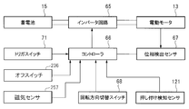
- FIG. 5 is a control block diagram of the driving machine 201 of this embodiment.
- the inverter circuit 65 is a circuit that generates a three-phase alternating current (excitation current) for driving the electric motor 13 from the direct current from the storage battery 15, and an inverter circuit board 83 (see FIG. 5) provided on the rear end side of the electric motor 13. 1).
- the inverter circuit 65 includes six switching elements 84 (see FIG. 1) connected to the coil of the stator 18 of the electric motor 13, and on / off of the plurality of switching elements 84 is controlled by the controller 66.
- the controller 66 controls the rotation of the electric motor 13 at the time of hitting the nail 11 (second process) and also performs the rotation control at the time of pressurization (first process) of the pneumatic chamber 249 using the electric motor 13.
- the controller 66 includes a microcomputer (not shown) (hereinafter referred to as “microcomputer”).
- the electric motor 13 is provided with a phase detection sensor 67 that detects the phase in the rotational direction of the rotor 19.
- the phase detection sensor 67 can be realized by including a plurality of Hall ICs or the like that detect the magnetic field of the permanent magnet included in the rotor 19 of the electric motor 13.
- the controller 66 is based on the signal from the phase detection sensor 67. The position and the number of rotations in the rotation direction can be obtained. Based on the signal from the phase detection sensor 67 and the gear ratio of the speed reducer 27, the controller 66 estimates the position in the rotational direction of the rotating body 38, that is, the rotational angle.
- a rotation direction changeover switch 68 that switches the rotation direction of the rotor 19 of the electric motor 13 is provided.
- the rotation direction changeover switch 68 is operated by an operator.
- the rotation direction changeover switch 68 has forward and reverse operation positions.
- an off switch 236 that detects the completion of driving of the nail 11 and a signal from the magnetic sensor 257 that detects whether or not the blade 48 has reached bottom dead center are input to the controller 66.
- the controller 66 processes the signal input from the phase detection sensor 67 to estimate the position of the piston 47 in the direction of the center line B1 of the cylinder 46.
- the trigger switch 71 (see FIG. 1) is a switch mechanism that is turned on and off by an operator operating the trigger 72 (see FIG. 1).
- a signal from the trigger switch 71 is input to the controller 66. Further, a pressing detection sensor 121 that detects whether or not the push rod 104 is pressed against the object is provided, and a signal output from the pressing detection sensor 121 is input to the controller 66.
- the controller 66 controls the rotation, stop, rotation speed, and rotation direction of the electric motor 13 based on signals from these switches and sensors.
- the controller 66 controls the inverter circuit 65 to supply current to the coil 21 and rotate the rotor 19 of the electric motor 13.
- the controller 66 controls the direction of the current flowing through the coil 21 based on the signal from the rotation direction changeover switch 68 and determines the rotation direction of the rotor 19.
- the controller 66 detects the position of the rotor 19 in the rotational direction based on the signal of the phase detection sensor 67, and controls the timing for turning on / off the switching element of the inverter circuit 65 and the ON ratio of the switching element, that is, the duty ratio. To do. In this way, the number of rotations of the rotor 19 per unit time is controlled.
- the electric motor 13 can switch the rotation direction of the rotor 19 between forward rotation and reverse rotation by switching the direction of current supply to the coil 21.
- the rotational force of the output shaft 24 is transmitted to the drive shaft 234 via the speed reducer 27.
- the first step of increasing the air pressure in the air pressure chamber 249 is performed in advance if necessary.
- the first step is a preparatory step prior to the start of the striking work, and should be performed only when the pressure in the pneumatic chamber 249 becomes low (for example, every few weeks to several months).
- the second step (normal driving operation) ) Can be executed. In the second step, when the operator presses the push rod 104 against the object and pulls the trigger 72, the air pressure in the air pressure chamber 249 further increases and the nail 11 is hit.
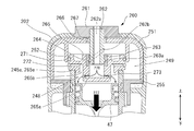
- FIGS. 6 to 8 are partially enlarged views of the vicinity of the outside air intake valve 260 provided in the pressure accumulating vessel 250 of FIG.
- FIG. 6 shows a state in which the outside air intake valve 260 is closed, and intake of outside air into the pressure accumulating vessel 250 is prohibited.
- the outside air intake valve 260 is an on-off valve mechanism that is provided so as to pass through a through hole 251b provided on the upper side of the pressure accumulating vessel 250, and from the outside air to the pneumatic chamber 249 side in the open state (FIGS. 7 and 8). Inflow of air is allowed, and in the closed state (FIG.
- the pressure accumulating container 250 is accommodated inside the synthetic resin main body housing 202, and a cushion material 270 is provided below the flange portion 255 so as to prevent the pressure accumulating container 250 from rattling.
- the cylinder portion of the cylinder 245 and the flange portion 255 is screwed by a male screw 245c formed on the cylinder 245 side and a female screw 255c formed on the inner peripheral side of the flange portion 255, and further, two O-rings are provided above the screwed portion.
- the confidentiality is enhanced by interposing 256a and 256b.
- the outside air intake valve 260 includes a selector 265 that is a main component of the valve mechanism, a cylindrical sleeve 262 that holds the selector 265 and moves it in the axial direction (in the direction of the axis B1), and the rotational force of the cylindrical sleeve 262 is selected by the selector 265.
- 7 includes a movable mechanism (264 and 262b and 263a shown in FIG. 7) that converts the moving force in the axial direction of the shaft, and a switching lever 261 for rotating the cylindrical sleeve 262.
- the switching lever 261 is a knob disposed inside a through hole 202b opened in the upper portion of the main body housing 202, and fixes a hollow cylindrical sleeve 262 having an outside air intake passage 262a formed in the center.
- a through hole 261a is also formed in the upper center of the switching lever 261 and communicates with the outside air intake passage 262a.
- the cylindrical sleeve 262 has a ring-shaped metal 266 attached to a through hole formed in the container main body 251 and is held by the metal 266 so as to be movable in the B1 axis direction.
- a washer 267 is interposed between the switching lever 261 and the cylindrical sleeve 262.
- a selector 265 is provided below the cylindrical sleeve 262.
- the selector 265 is configured to be movable in the axial direction while rotating, and has a cup-shaped inner wall surface that contacts the outer peripheral side of the cylindrical sleeve 262. In the vicinity of the bottom (lower side) of the cup-shaped inner wall surface, a communication path 265 a for communicating the cup-shaped inner portion and the outer portion of the selector 265 is formed.
- the communication path 265a is two or more through holes extending radially outward from the axis of the selector 265. When the lower end of the cylindrical sleeve 262 is separated from the bottom surface of the selector 265, the communication path 265a
- the intake passage 262a and the pneumatic chamber 249 can communicate with each other.
- a groove portion is formed at the outer peripheral side outlet of the communication path 265a so as to be continuous in the circumferential direction, and a rubber O-ring 273 is disposed in the groove portion.
- the O-ring 273 functions as a check valve, and the flow of air from the air pressure chamber 249 side to the communication path 265a side is blocked. Conversely, when there is an air pressure difference, the air pressure chamber 249 from the communication path 265a side. Air flow to the side is allowed.
- the cylinder 245 is further formed with a cylindrical recess 265b from the bottom to the top in a cylindrical shape, and two or a plurality of communication passages 265c extending radially outward from the cylindrical recess 265b.
- a groove portion is formed at the outer peripheral side outlet of the communication passage 265c so as to be continuous in the circumferential direction, and an O-ring 272 made of rubber and serving as a check valve is disposed in the groove portion.
- the movable mechanism that converts the rotational force of the cylindrical sleeve 262 into the moving force in the axial direction of the selector 265 includes a collar 263 and a steel ball 264 provided on the inner peripheral side of the selector 265.
- a hemispherical recess 263a (see FIG. 7) is formed on the inner peripheral surface of the collar 263.
- a spline groove 262b is formed which is formed by a rotation angle of 180 degrees while changing in the circumferential direction and the axial direction.
- a steel ball 264 is disposed between the spline groove 262b and the recess 263a.
- the selector 265 is moved downward by the movable mechanism, and a step 265 e formed on the lower side of the selector 265 is brought into close contact with the opening 245 a at the upper end of the cylinder 245, so that the space between the pneumatic chamber 249 and the cylinder chamber 248 is obtained. Isolate.
- the O-ring 271 disposed in the upper outer peripheral groove 265d (see FIG. 6) of the selector 265 is in contact with the inner wall portion of the cylindrical portion 252 formed on the inner peripheral side of the container body portion 251, the pneumatic chamber 249 is kept sealed from the outside air or the cylinder chamber 248.
- This O-ring 272 allows only the air flow from the cylinder chamber 248 to the pneumatic chamber 249 (when there is a pressure difference).
- the operation of increasing the air pressure in the air pressure chamber 249 in the first step is executed by moving the piston 47 in the cylinder chamber 248.
- Any power source can be used for the piston 47 as long as the piston 47 or the blade 48 can be moved.
- the blade 48 can be moved up and down by hand, or a dedicated movable tool can be used. Is possible.
- the air pressure chamber 249 and the cylinder chamber 248 are pressurized in the first step by using a drive source for moving the blade 48 during the striking operation, here, the electric motor 13.
- a brushless DC motor that can accurately detect the rotational position by a microcomputer and can perform forward and reverse control with high accuracy is used as the electric motor 13.
- the piston 47 that has reached the top dead center is lowered by reversing the electric motor 13 to the bottom dead center.
- the electric motor 13 is rotated forward again. To move to just before top dead center.
- the reverse rotation and the normal rotation of the electric motor 13 are performed within a range in which the rack 53 and the pinion 241 are not disengaged, and are controlled with high accuracy by a microcomputer included in the controller 66.
- the air pressure in the air pressure chamber 249 can be increased to about 3 to 5 atm.
- FIG. 9 A series of procedures shown in FIG. 9 can be executed by software using a program stored in advance by a microcomputer included in the controller 66.
- the switch lever 261 is rotated from the state shown in FIG. 6, the selector 265 is lowered as shown in FIG. 7, and the stepped portion 265e is in contact with the opening 245a of the cylinder 245.
- the mode switch (switching lever 261) is turned on ("open") and is started (step 281).
- a sensor for detecting the position of the switching lever 261 may be provided so that the controller 66 can detect that the switching lever 261 has been switched.
- the microcomputer detects whether or not the pressure accumulation mode is turned on by rotating the switching lever 261 (step 281). If not in the pressure accumulation mode, the system waits until the operator switches to the pressure accumulation mode (step 289). When in the pressure accumulation mode, the microcomputer detects whether or not the nail 11 remains in the magazine 16 and the nail injection path (step 282). For this detection, it is preferable to provide a known stopper sensor or the like for detecting whether or not the nail 11 is not loaded in the injection path 256 and whether or not the nail 11 is present. If the nail 11 remains in the magazine 16 or the injection path, a warning lamp indicating that the nail 11 remains is blinked and waits until the operator removes the nail 11 (step 290).
- step 283 when the magazine 16 and the nail 11 in the injection path 256 disappear, the electric motor 13 can be rotated.
- the microcomputer reversely rotates the electric motor 13 and reversely rotates the hoisting cam (rotating body 238) to move the piston 47 to the bottom dead center side (step 283).
- outside air is sucked into the piston chamber 248 as indicated by an arrow 276 in FIG.
- step 283 is instantaneously ended.
- the microcomputer detects the current value I flowing to the motor when the cam (rotating body 238) rotates in reverse, thereby detecting whether the nail 11 is clogged in the injection path, that is, whether the nail is clogged. To do. This can be determined by whether or not the detected current value I exceeds a current threshold value I 0 indicating nail clogging (step 284). Since the microcomputer constantly monitors the current value I through a current detection circuit included in the control circuit for driving the electric motor 13, if the detected value is used, it is not necessary to provide a new current detection means. Here, when the piston 47 is lowered, if the electric motor 13 can be lowered smoothly, the current value I flowing through the motor does not increase so much.
- the microcomputer rotates the electric motor 13 in the forward direction (rotation in the direction in which the piston 47 is wound up when hitting, in the direction indicated by the arrow in FIG. 2), and the cam for rotation (rotating body 238) is moved forward.
- the piston 47 is moved from the bottom dead center to the vicinity of the top dead center (front) (step 285).
- the air in the cylinder chamber 248 air sucked from the outside
- the pneumatic chamber 249 as indicated by an arrow 249 shown in FIG.
- the engagement state between the hoisting cam (rotating body 238) and the rack 53 of the blade 48 is disengaged, and the piston 47 moves rapidly with the pressure of the accumulated air.
- the microcomputer determines whether or not pressure accumulation performed by the lowering and raising operations of the piston 47 is completed (step 286). Whether or not this pressure accumulation (pressurizing operation) is completed can be carried out, for example, by any of the following methods.
- (1) Whether or not the current value I flowing through the electric motor 13 when the piston 47 is moved from the bottom dead center side to the top dead center side is detected, and whether or not it has become larger than the threshold value I 1 when the pressure accumulation operation is completed Determine. If the pressure in the pneumatic chamber 249 (here, it is assumed that the pressure is increased to about 3 to 5 atm in the pressure accumulation mode) increases, the load when moving the piston 47 from the bottom dead center to the top dead center increases. This is because the current value I increases as the load increases.
- the microcomputer counts how many times the operation for one stroke of returning the piston 47 from the position just before the top dead center to the bottom dead center and raising the piston 47 from the position just before the top dead center to the position just before the top dead center is executed. When the number of times the piston has been reciprocated is executed for a predetermined number of times N, the pressure accumulation operation is terminated.
- This threshold can be set to 3 times, for example.
- the microcomputer detects whether or not the pressure accumulation mode is turned off by rotating the switching lever 261 (step 287). If the pressure accumulation mode remains, the operator waits until the operator operates the switching lever 261 to turn off the pressure accumulation mode (step 292). When the pressure accumulation mode is turned off, that is, when the switching lever 261 is returned to the state shown in FIG. 6, the microcomputer returns the piston 47 to the initial position (bottom dead center or a predetermined position near the bottom dead center) (step 288). ), The pressure accumulation process of the pneumatic chamber 249 in the first step is terminated. Thereafter, the operator can execute an actual nail driving operation (second step).
- the pressure of the gas in the pneumatic chamber 249 can be increased by the movement of the piston 47 driven by the electric motor 13, so that the pressure drop in the pneumatic chamber due to many years of use is plagued. Long life and high performance driving machine can be realized.
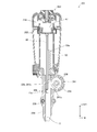
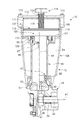
- the driving machine 301 of the second embodiment is different from the first embodiment in that a manual leak mechanism for releasing the internal air to the outside when the pressure in the pneumatic chamber 349 exceeds a predetermined value, that is, a leak
- the valve 360 is provided in the pressure accumulation container 350. Therefore, the shape of the pressure accumulating vessel 350 is extended in the radial direction, and the leak valve 360 is provided at a position adjacent to the outside air intake valve 260 on the upper surface.
- the structure and function of the outside air intake valve 260 are the same as those described in the first embodiment.
- the pressure accumulating vessel 350 is manufactured in a two-split type with a container main body portion 351 and a flange portion 355, but the container for storing compressed air may be an integral type or a divided type.
- Other structures may be used.
- the shape of the upper portion of the main body housing 302 of the driving machine 301 has been changed along with the change in the shape of the pressure accumulating vessel 350. Except for the shape near the pressure accumulating vessel 350, the other portions are the same as those in the first embodiment.
- the structure is the same as the embedded machine 201.
- FIG. 11 is a longitudinal sectional view showing the detailed structure of the leak valve 360.
- the leak valve 360 has a function as a “release valve” that releases internal air to the outside when the pressure in the pneumatic chamber 349 (see FIG. 10) exceeds a predetermined value.
- a function as a “leak valve” capable of discharging 349 air was provided.
- the optional exhaust function using the leak valve is convenient when removing the clogged nail 11 when the nail 11 is clogged in the injection path 256 (see FIG. 2) formed in the nose portion 254. This is because it may be difficult to move the blade 48 even if the nail 11 is removed while the pressure in the pneumatic chamber 349 is high.
- the air in the pneumatic chamber 349 is removed when the nail 11 is removed, the inside of the pneumatic chamber 349 and the cylinder chamber 248 becomes atmospheric pressure, so that the operator can easily move the blade 48. . Furthermore, if the air pressure chamber 349 is returned to the atmospheric pressure, the force for moving the piston 47 is lost, so there is no possibility that the striking operation is erroneously performed, and the safety is further improved.
- a through hole 353 serving as an air outlet in the pneumatic chamber 349 is formed in the container main body 351 of the pressure accumulating container 350, and air is discharged from the through hole 353 in a predetermined state.
- An allowed leak valve 360 was provided.
- the leak valve 360 includes a cylindrical portion that can move in the axial direction inside the large diameter portion 351c and the small diameter portion 351d, and a large diameter portion 351c and a small diameter portion 351d that project the container main body portion 351 in a cup shape.
- Plunger 370 plunger holder 361 for holding plunger 370 in container body 351, push button 385 for moving plunger 370, ball 381 disposed inside cylindrical plunger 370, ball 381 And a pusher 382 for biasing in a predetermined direction.
- Plunger 370 is formed with a plurality of passages (communication passages 371 and 374) and a throttle portion 372 for performing a valve mechanism with ball 381, and rubber for maintaining a tight seal with plunger holder 361 on the outer peripheral surface.
- Made O-rings 376-378 are provided.
- the ball 381 is inserted into the plunger 370 from the outside of the container body 351, is urged by the pusher 382 and the coil spring 383, and is held by the metal plate 384.
- the metal plate 384 is prevented from coming off by a push button 385 made of synthetic resin.
- a retaining ring 386 is inserted below the push button 385.
- the plunger holder 361 holds the plunger 370 on the container main body 351 and forms a predetermined air passage with the groove on the outer peripheral side of the plunger 370 or closes it.
- the plunger holder 361 passes through the through hole 302c of the main body housing 302 and is press-fitted into the large diameter portion 351c of the container main body portion 351.
- An O-ring 363 is provided to maintain airtightness between them. It is done.
- a discharge pipe line 365 extending in a direction orthogonal to the axial direction of the container main body 351 is provided.
- the discharge pipe 365 is formed in a part of the container main body 351 by a drill or the like, and communicates the outside of the main body with the lateral hole 361 c formed in the plunger holder 361.
- FIG. 11 (1) shows a state when the driving machine 301 is not used or when a normal hitting operation is performed.
- (2) shows a state in which the push button 385 is pushed down in the direction of the arrow 395 by the operator.
- the push button 385 moves downward in the axial direction, as shown by the arrow 391, the push button 385 is removed from the through hole 353.
- An air passage to the exhaust line 365 is defined.
- the through hole 353 passes through the gap between the lower end portion of the plunger holder 361 and the inside of the large diameter portion 351c, and passes through the gap created between the inclined surface portion on the inner peripheral side of the plunger holder 361 and the O-ring 377.
- the air flows through the wide groove 375 continuous in the circumferential direction so as to communicate from the lower side in the axial direction, and the air is discharged to the outside from the discharge pipe 365 as indicated by an arrow 391.
- a high-pressure air discharge sound is generated.
- the plunger 370 returns to the state (1) by the restoring force of the coil spring 379.
- the pressure reduction of the pressure accumulating vessel 350 by pressing the push button 385 is a case where a nail is clogged and can be operated when removing the clogged nail.
- FIG. 11 (3) is a diagram showing a situation when acting as a release valve when the air pressure chamber 349 of the driving machine 301 is pressurized and air of a predetermined amount or more is introduced.
- the driving machine 301 of this embodiment assumes driving of a nail having a length of about 50 to 90 mm.
- the pneumatic chamber is set to about 5 to 8 atm.
- the striking process in which actual driving is performed, the air pressure chamber increases to a maximum of about 10 to 14 atm. If the striking process is performed after the accumulated pressure in the first process is over a specified amount, the pressure in the pneumatic chamber 349 will exceed a predetermined value.
- the air flows around the ball 381, and excess air is discharged to the outside through the communication path 374 as indicated by an arrow 393.
- the arrow 393 is illustrated so as to be discharged leftward, but the same is discharged to the right.
- the spring force of the coil spring 383 becomes stronger than the pressure in the air pressure chamber 349 (arrow 392), and the ball 381 is again pressed against the throttle portion 372.
- the state of FIG. 11 (1) is restored and the sealed state in the pneumatic chamber 349 is maintained.
- the operator when the nail is clogged and the nail is taken out, the operator can release the high-pressure air in the pneumatic chamber 349, so that the nail is taken out in a safe state. Can do.
- the high pressure air in the pneumatic chamber 349 can be released at the operator's request, so that the seal portion of the pneumatic chamber, the seal portion of the piston, etc. may deteriorate quickly over time. Can be prevented.
- excess air inside can be automatically discharged, so that the pressurizing operation in the first step does not fail.
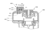
- FIG. 12 shows a modification of the second embodiment, in which the leak valve 360 in FIG. 11 is replaced with an electromagnetic valve 460.
- the electromagnetic valve 460 is disposed so as to penetrate the container main body 451 and moves the discharge pipe 461 that forms the communication path 462 of the discharged air, the valve 463 for opening or closing the communication path 462, and the valve 463.
- a solenoid actuator 464 is provided.
- the discharge pipe 461 is a substantially cylindrical member whose center in the axial direction is closed.
- the discharge pipe 461 is attached to the through hole 451b of the container body 451, and is attached with a rubber O-ring 468 interposed therebetween.
- a valve 463 is fixed to the iron core 467, and when the coil 466 is energized, the valve 463 moves so as to approach the communication path 462 side, and when the coil 466 is de-energized, the valve 463 is operated by the action of a spring (not shown). 463 moves to the side away from the communication path 462.
- a space is formed between the recessed portion of the discharge pipe 461 and the valve 463 so that the passages 462a and 462b communicate with each other, so that the pressurized air in the pneumatic chamber 449 is discharged. It can be discharged to the outside through the tube 461. In this way, by driving the solenoid actuator 464 under the control of the microcomputer, the communication path 462 can be opened or shut off.
- the microcomputer when an abnormality such as a nail clogging occurs and the microcomputer detects that the nail needs to be removed, the microcomputer operates the electromagnetic valve 460 to operate the pneumatic chamber. Since the high-pressure air of 449 can be released, the operator can take out the nail in a safe state. In addition, after the nail removal is completed, the operator can operate the outside air intake valve 260 to execute the pressure accumulation mode in which the pressure in the air pressure chamber 449 in the first step is increased. it can.
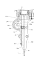
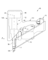
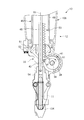
- FIG. 13 The basic configuration of FIG. 13, in particular, a nail feed mechanism such as a magazine 16, driving by the electric motor 13, the shape of the grip 101 and the mounting portion 1, the point that uses the storage battery 15 as a power source, These are substantially the same as the driving machine 201 described in the first embodiment.
- a different main point is a striking mechanism 12 for striking the nail 11, and a mechanism for pressurizing the pneumatic chamber is different.
- pressure accumulation is not performed using the piston 47 as in the first embodiment, but the pneumatic chamber is configured by a movable second cylinder 46, and the cylinder 46 is connected to the electric motor 13 (described later). It can be moved up and down by the driving force.
- the electric motor 13 (not shown) is provided in the motor housing 17, and the structure thereof is a brushless DC motor of the same type as that described in FIG.
- a reduction gear 27 of the same type as that described in FIG. 1 is accommodated in the casing 33 adjacent to the motor housing 17, and the casing 33 is connected to a cylindrical nose portion 54.
- FIG. 14 is a side view as seen from the direction A in FIG.
- the rotational driving force of the electric motor 13 is transmitted to the drive shaft 34 and the driven shaft 35 via the output of the speed reducer 27.
- two power transmission paths are provided: a first power transmission path driven by the rotation of the driven shaft 35 and a second power transmission path driven by the rotation of the drive shaft 34.
- the first power transmission path is movable in the vertical direction of the movable second cylinder 46 using the gear 44 rotated by the driven shaft 35.
- the second power transmission path moves the piston 47 (see FIG. 15) from the bottom dead center to the top dead center by moving the blade 48 upward using the gear 41 rotated by the drive shaft 34.
- the drive shaft 34 is disposed concentrically with the output shaft 24 (see FIG. 1) of the electric motor 13 and is rotatable about the axis A1.
- a rotating body 37 and a rotating body 38 are attached to the drive shaft 34.
- a gear 40 is provided on the outer peripheral surface of the rotating body 37, and the rotational force is transmitted to the driven shaft 35 side by the gear 40.
- a gear 40 is provided on the outer peripheral surface of the rotating body 37.
- a one-way clutch 39 (see FIG. 15) for connecting or disconnecting the power transmission path between the rotator 37 and the drive shaft 34 is provided, and when the drive shaft 34 rotates counterclockwise in FIG. This is transmitted to the rotating body 37.
- the one-way clutch 39 does not transmit the rotational force of the drive shaft 34 to the rotating body 37 even if the drive shaft 34 rotates clockwise in FIG. That is, the one-way clutch 39 connects or disconnects the power transmission path between the drive shaft 34 and the driven shaft 35 according to the rotation direction of the drive shaft 34.
- a gear 41 is provided on the outer peripheral surface of the rotating body 38 within a predetermined angle range.
- a roller 42 is provided at a location where the gear 41 is not provided in the rotational direction of the rotating body 38. A part of the outer peripheral surface of the roller 42 is disposed outside the outer peripheral surface of the rotating body 38. The roller 42 is rotatably supported.
- a gear 44 is provided on the driven shaft 35.
- the gear 44 meshes with the gear 40.
- the blade 48 is disposed along the center line B1 and is movable in the shaft hole 52 (see FIG. 15).
- the casing 33 is provided with a rotation stopper 73 that is a holding member that restricts the rotation of the rotating body 60.
- the rotation stopper 73 can swing around the support shaft 74.
- the rotation stopper 73 meshes with the gear 61 to prevent the rotating body 60 from rotating counterclockwise in FIG. 14 and to allow it to rotate clockwise.
- the gear 61 and the rotation stopper 73 constitute a ratchet mechanism.
- the blade 48 is provided with a rack 53 in the length direction.
- the gear 41 can be engaged with the rack 53 or can be detached from the rack 53.
- the casing 33 has a cylindrical nose portion 54, and the blade 48 is movable in the nose portion 54.
- the nose portion 54 is exposed outside the cover 100 (see FIG. 13).
- a push rod 104 is provided on the nose portion 54.
- the push rod 104 is movable within a predetermined range in the direction along the center line B1 with respect to the nose portion 54.
- the push rod 104 is stopped by being pushed in the direction along the center line B1 by the force of the compression spring 105 (see FIG. 15).
- the push rod 104 moves in the direction of the center line B1 against the force of the compression spring 105 (see FIG. 15) and stops.
- the striking mechanism 12 includes a first cylinder 45, a second cylinder 46, a piston 47, and a blade 48.
- the cylinder 45 and the cylinder 46 are disposed in the cover 100 (see FIG. 13).
- the cylinder 45 includes a cylindrical portion 49 and an outward flange 50 that is continuous with the cylindrical portion 49.
- a center line B ⁇ b> 1 of the cylindrical portion 49 intersects the axis A ⁇ b> 1 at a substantially right angle, and a first end (lower end) in a direction along the center line B ⁇ b> 1 of the cylindrical portion 49 is fixed to the casing 33.
- a part of the power transmission mechanism 14 is provided in the casing 33.
- the power transmission mechanism 14 includes a drive shaft 34 and a driven shaft 35 that are arranged in parallel to each other.
- the drive shaft 34 is rotatably supported by the casing 33 via a bearing 36.
- the drive shaft 34 is disposed concentrically with the output shaft 24 and is rotatable about the axis D1.
- a rotating body 37 and a rotating body 38 are attached to the drive shaft 34.
- the rotating body 37 is disposed between the rotating body 38 and the speed reducer 27 in the direction along the axis A1.
- the rotation direction of the drive shaft 34 is the same as the rotation direction of the rotor 19 of the electric motor 13.
- a one-way clutch 43 is provided between the rotating body 38 and the drive shaft 34. When the drive shaft 34 rotates clockwise in FIG. 14, the one-way clutch 43 transmits the rotational force of the drive shaft 34 to the rotating body 38, and when it rotates counterclockwise, the rotational force of the drive shaft 34 is transmitted to the rotating body 38. Do not communicate.
- a gear 40 is provided on the outer peripheral surface of the rotating body 37.
- a one-way clutch 39 that connects or disconnects the power transmission path between the rotating body 37 and the drive shaft 34 is provided.
- the one-way clutch 39 transmits the rotational force of the drive shaft 34 to the rotating body 37 when the drive shaft 34 rotates counterclockwise in FIG.
- the one-way clutch 39 does not transmit the rotational force of the drive shaft 34 to the rotating body 37 even if the drive shaft 34 rotates clockwise in FIG. That is, the one-way clutch 39 connects or disconnects the power transmission path between the drive shaft 34 and the driven shaft 35 according to the rotation direction of the drive shaft 34.
- the flange 50 is provided at the second end (upper end) of the cylindrical portion 49 in a direction along the center line B ⁇ b> 1 that is the axis of the cylinder 45. Further, between the cylindrical portion 49 and the casing 33, an annular damper 51 integrally formed of a rubber-like elastic body is provided.
- the damper 51 includes a shaft hole 52.
- the piston 47 can reciprocate in the direction along the center line B ⁇ b> 1 within the cylindrical portion 49, and a seal member 55 is attached to the outer peripheral surface of the piston 47.
- the shaft-shaped blade 48 is connected to or fixed to the piston 47.
- the cylinder 46 includes a cylindrical portion 56 and a disc portion 57 that continues to the cylindrical portion 56.
- the flange 50 is disposed in the cylindrical portion 56, and the cylinder 46 is movable in a direction along the center line B ⁇ b> 1 with respect to the cylinder 45.
- a seal member 103 is attached to the outer peripheral surface of the flange 50, and a pneumatic chamber 58 is formed in the cylinder 46.
- the pneumatic chamber 58 communicates with the cylinder 45.
- a breathing hole 59 that penetrates the cylindrical portion 56 in the radial direction is provided.
- the breathing hole 59 connects the inside and outside of the pneumatic chamber 58.
- the seal members 55 and 103 hermetically seal the pneumatic chamber 58. Air that is a compressible fluid enters and exits the pneumatic chamber 58 through the breathing hole 59.
- a rotating body 60 having a gear 61 on the outer peripheral surface is attached to the driven shaft 35 at a location exposed outside the casing 33.
- the rotating body 60 can rotate around the axis D1 together with the driven shaft 35.
- a support shaft 62 is provided at a position eccentric from the axis D1.
- the cylinder 46 is provided with a support shaft 63.
- a connecting rod 64 that connects the rotating body 60 and the cylinder 46 is provided.
- the connecting rod 64 is rotatably attached to the support shafts 62 and 63 and constitutes an opening / closing mechanism that opens the air passage together with the rotating body 60.
- the electric motor 13 is stopped.
- the cylinder 46 is stopped at the initial position shown in FIGS.
- the pneumatic chamber 58 is connected to the outside of the pneumatic chamber 58 via the breathing hole 59. That is, the initial pressure in the pneumatic chamber 58 and the cylinder 45 is the same as the atmospheric pressure. Further, the piston 47 is stopped in contact with the damper 51, and the gear 41 is not engaged with the rack 53 (see FIG. 14).
- the operator operates the rotation direction changeover switch 68 (see FIG. 5) in the preparation step (first step) before hitting, and sets the rotation direction of the drive shaft 34 in the counterclockwise direction in FIG.
- An operating force is applied to the trigger 72.
- the push rod 104 does not have to be pressed against the object, but may not move unless pressed.
- the trigger switch 71 is turned on, the electric motor 13 rotates.
- the drive shaft 34 is rotated counterclockwise in FIG. 14 by the rotational force of the electric motor 13, and the rotational force of the drive shaft 34 is transmitted to the driven shaft 35 via the one-way clutch 39.
- the rotating body 60 integrally rotates clockwise in FIG.
- the controller 66 stops the electric motor 13 when the rotation angle of the driven shaft 35 reaches a position rotated by a predetermined angle less than 180 from the position where the rotation starts in FIG.
- the cylinder 46 stops in the vicinity (bottom dead center) before the disk portion 57 contacts the flange 50 of the cylinder 45.
- the disc part 57 of the cylinder 46 receives the pressure of the pneumatic chamber 58, and the cylinder 46 is urged in the direction of rising along the center line B1.
- the urging force received by the cylinder 46 is transmitted to the rotating body 60 via the connecting rod 64. That is, the rotating body 60 receives a counterclockwise rotational force in FIG.
- the operator operates the rotation direction changeover switch 68 to perform the striking process (second process), and sets the rotation direction of the electric motor 13 to be opposite to the first process.
- the electric motor 13 is stopped when the rotation direction is set.
- the electric motor 13 rotates when the trigger 72 is operated while the push rod 104 is pressed against the object, and the drive shaft 34 rotates clockwise in FIG.
- the one-way clutch 39 does not transmit the rotational force of the drive shaft 34 to the driven shaft 35.
- the piston 47 is rapidly lowered toward the damper 51 by the air pressure in the air pressure chamber 58 and the cylinder 45, and the blade 48 strikes the nail 11 and drives it into the object. Then, the piston 47 collides with the damper 51 and stops.
- the electric motor 13 rotates even after the gear 41 is separated from the rack 53, and the electric motor 13 stops when the gear 41 reaches a predetermined position, that is, before the gear 41 is engaged with the rack 53. Thereafter, when the operator releases the push rod 104 from the object, the driving operation of the nail 11 is completed.
- the nail 11 is not set in the magazine 16, and when the piston 47 is stopped, the operator grasps the rotation stopper 73 by hand and rotates it clockwise in FIG. 14.
- the pressure in the pneumatic chamber 58 and the cylinder 45 can be reduced.
- the pressure in the pneumatic chamber 58 and the cylinder 45 can be reduced by connecting the pneumatic chamber 58 to the breathing hole 59, the nail 11 can be easily removed when the nail 11 is clogged. Moreover, since the air pressure of the air pressure chamber 58 can be released when the driving machine 10 is stored, it is not necessary to provide a seal member for maintaining the high pressure of the air chamber.
- the driving machine 10 of FIG. 17 includes the same structure and the same elements as the driving machine 10 shown in the third embodiment.
- the cylinder 45 has a cylindrical shape, and has a partition wall 75 attached to the cylinder 45 instead of being provided with the flange 50 described in the third embodiment.
- the partition wall 75 includes a cylindrical portion 76 that can move along the outer peripheral surface of the cylindrical portion 49 of the cylinder 45, and an outward flange 77 that is continuous with the cylindrical portion 76.
- the outer diameter of the flange 77 is less than the inner diameter of the cylindrical portion 56.
- the partition wall 75 is movable with respect to the cylinder 45 and the cylinder 46 in a direction along the center line B1.
- a seal member 78 is attached to the inner peripheral surface of the cylindrical portion 76, and the seal member 78 hermetically seals between the outer peripheral surface of the cylindrical portion 49 and the partition wall 75.
- a seal member 79 is attached to the outer peripheral surface of the flange 77. The seal member 79 hermetically seals between the inner peripheral surface of the cylindrical portion 56 and the flange 77.
- a support shaft 80 is provided on the outer peripheral surface of the cylindrical portion 76, and the connecting rod 64 is rotatably connected to the support shaft 80. That is, the rotating body 60 and the partition 75 are connected via the connecting rod 64 so as to be able to transmit power.
- the arrangement range of the support shaft 80 and the connecting rod 64 is less than the inner diameter of the cylindrical portion 56 in the radial direction of the center line B1.
- the 1st process which raises the air pressure of the air pressure chamber 58 is performed.
- the air pressure in the air pressure chamber 58 is further increased and the nail 11 is hit.
- the operator operates the rotation direction changeover switch 68 to switch the rotation direction of the electric motor 13 and sets the rotation direction of the drive shaft 34 in the first step to the counterclockwise direction in FIG.
- the partition 75 is stopped at the initial position in FIG. 17 before the drive shaft 34 starts to rotate.
- the pneumatic chamber 58 is connected to the outside of the pneumatic chamber 58 through the breathing hole 59. That is, the pressure in the pneumatic chamber 58 and the cylinder 45 is the same as the atmospheric pressure. Further, the piston 47 comes into contact with the damper 51 and stops.
- the total length of the driving machine 10 in the direction along the center line B1 is unchanged.
- the total length of the driving machine 10 is the height from the tip of the push rod 104 to the upper end of the cylinder 45.
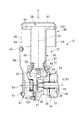
- the driving machine 10 shown in FIG. 19 uses the electric motor 13, the speed reducer 27, the rotating body 38, the piston 47, the roller 42, the blade 48, and the cylinder 45 having the same structure as the driving machine 10 of the fourth embodiment.
- the first power transmission path portion (the driven shaft 35, the rotating body 37, the one-way clutch 43, the connecting rod 64) of the fourth embodiment is not provided.
- the driving machine 10 includes an outer cylinder 106 fixed to the casing 33, and the cylinder 45 is disposed in the outer cylinder 106.
- An inner cylinder 107 is provided in the outer cylinder 106.
- the cylinder 45 is disposed between the inner cylinder 107 and the casing 33 in a direction along the center line B1.
- the inner cylinder 107 includes a large diameter portion 108 and a small diameter portion 109.
- the small diameter portion 109 is disposed between the large diameter portion 108 and the casing 33 in the direction along the center line B1.
- the inner diameter of the large diameter portion 108 is larger than the inner diameter of the small diameter portion 109.
- the inner cylinder 107 has a connection portion 117 that connects the large diameter portion 108 and the small diameter portion 109.
- the connection part 117 is annular.
- a breathing hole 111 penetrating the large-diameter portion 108 in the radial direction is provided.
- the end of the cylinder 45 in the length direction is fixed to the small diameter portion 109.
- a seal member 110 that seals between the outer peripheral surface of the cylinder 45 and the inner peripheral surface of the small diameter portion 109 is provided.
- a holder 112 is fixed to the outer cylinder 106.
- a screw member 113 for fixing the holder 112 to the outer cylinder 106 is provided.
- the inner cylinder 107 is positioned and fixed with respect to the outer cylinder 106 by a holder 112 in a direction along the center line B1.
- the breathing hole 111 is connected to the outside of the outer cylinder 106 via the inside of the outer cylinder 106.
- a plunger 114 is attached to the holder 112.
- the plunger 114 is a mechanism using a screw member, and a male screw of the shaft portion 115 of the plunger 114 is formed.
- the holder 112 is provided with a female screw hole 116, and the shaft portion 115 is inserted into the female screw hole 116.
- the operator can manually rotate the plunger 114 forward and backward, and the plunger 114 can move in the direction along the center line B1 when rotated in any direction. When the rotation direction of the plunger 114 is different, the direction in which the plunger 114 moves along the center line B1 is different.
- a movable partition wall 118 is attached to the tip of the shaft portion 115.
- the movable partition wall 118 is disposed in the large diameter portion 108.
- the movable partition wall 118 is a disc that can rotate around the center line B ⁇ b> 1 with respect to the shaft portion 115.
- the outer diameter of the movable partition wall 118 is less than the inner diameter of the large-diameter portion 108, and an annular seal member 119 is attached to the outer peripheral surface of the movable partition wall 118.
- a pneumatic chamber 120 is formed from the space between the movable partition wall 118 and the connection portion 117 to the inside of the cylinder 45.
- the seal members 55, 110, and 119 hermetically seal the pneumatic chamber 120.
- the breathing hole 111 connects the inside and outside of the pneumatic chamber 120.
- the configuration and operation of the second power transmission path portion including the rotating body 38 are the same as those in the third to fourth embodiments. However, since the rotation direction changeover switch 68 for switching the rotation direction of the electric motor 13 is unnecessary, it is not provided.
- the operator uses the driving machine 10
- the operator performs the first step of increasing the air pressure in the air pressure chamber 120 before pressing the push rod 104 against the object.
- the worker further increases the air pressure in the air pressure chamber 120 in the second step, and presses the push rod 104 against the object to hit the nail 11.
- the drive shaft 34 is stopped.
- the piston 47 is in contact with the damper 51 as shown on the right side of the center line B1 in FIG.
- the movable partition 118 is stopped at the position indicated by the two-dot chain line in FIG. That is, the pneumatic chamber 120 is connected to the outside of the outer cylinder 106 through the breathing hole 111, and the pressure of the pneumatic chamber 120 is the same as the atmospheric pressure.
- the operator rotates the plunger 114 in a predetermined direction using a spanner or the like, and moves the plunger 114 in the direction along the center line B1.
- the plunger 114 descends in a direction approaching the cylinder 45.
- the movable partition wall 118 blocks the pneumatic chamber 120 and the breathing hole 111, and the pressure of the pneumatic chamber 120 increases as the movable partition wall 118 moves.
- the operator stops the movable partition wall 118 at a predetermined position in the direction along the center line B1. For this reason, the pressure of the pneumatic chamber 120 is maintained at the first pressure higher than the atmospheric pressure.
- the operation in the second step is the same as in the third and fourth embodiments.
- the driving machine 10 in the fifth embodiment reduces the pressure of the pneumatic chamber 120 by rotating the plunger 114 in the direction opposite to that described above and moving the plunger 114 in the direction of the center line B1 away from the cylinder 45. be able to.
- the movable partition wall 118 rises in the direction away from the cylinder 45 together with the plunger 114, the seal member 119 reaches the breathing hole 111 and the holder 112 in the direction of the center line B1, and the breathing hole 111 is connected to the pneumatic chamber 120.
- the driving machine 10 of the fifth embodiment can obtain the same effects as the driving machine 10 of the fourth embodiment.
- the motor that transmits power to the drive shaft may be an engine, a hydraulic motor, or a pneumatic motor in addition to the electric motor.
- the electric motor may be either a brush motor or a brushless motor.
- the power source of the electric motor may be either a DC power source or an AC power source.
- the pneumatic chamber 58 and the cylinder 45 may be filled with compressed air whose initial pressure is higher than atmospheric pressure and lower than the first pressure.
- the driving machine 10 of each figure explaining each Example has shown centerline B1 as an up-down direction, ie, a perpendicular direction, the driving machine 10 inclines centerline B1 with respect to a perpendicular direction. Can be used.
- the object to be driven by the driving machine includes a U-shaped nail in addition to the shaft-shaped nail.
- the shaft-shaped nail includes a nail with a head or a nail without a head.
- the first pressure and the second pressure in the present invention are not fixed values, but differ depending on conditions such as the operation amount of the movable member and the pressure receiving area.
- the third and fourth driving machines 10 switch the rotation direction of the drive shaft 34 by switching the rotation direction of the rotor 19 of the electric motor 13.
- the drive shaft can be switched without switching the rotation direction of the electric motor 13.
- the rotation direction of 34 can be switched.
- Support shaft 75 ... Partition wall 76 ... Cylinder portion 77 ... Flange 78,79 ... Seal member 80 ... Support shaft 81 ... Control circuit board, 82a, 82b ... Bearing, 83 ... Inverter circuit board, 84 ... Switching element, 100 ... Cover, 101 ... Grip, 103 ... Seal member, 104 ... Push rod, 105 ... Compression spring, 106 ... Outside Cylinder, 107 ... Inner cylinder, 108 ... Large diameter portion, 109 ... Small diameter portion, 110 ... Seal member, 111 ... Breathing hole, 112 ... Holder, 113 ... Member, 1 DESCRIPTION OF SYMBOLS 4 ... Plunger, 115 ...
- Communication passage 265d ... Outer peripheral groove, 265e ... Step portion, 266 ... Metal, 270 ... Cushion material, 271 to 273 ... O-ring, 301 ... Driver, 302 ... Main body housing, 302c ... through hole, 303 ... grip portion, 349 ... pneumatic chamber, 350 ... accumulator, 351 ... container body portion, 351c ... large diameter portion, 351d ... small diameter portion, 353 ... through hole, 355 ... flange portion 360 ... Leak valve, 361 ... (leak) plunger holder, 361c ... Side hole, 363 ... Ring, 365 ... Outlet passage, 365a ... tip portion, 370 ...
Landscapes
- Engineering & Computer Science (AREA)
- Mechanical Engineering (AREA)
- Physics & Mathematics (AREA)
- Fluid Mechanics (AREA)
- Portable Nailing Machines And Staplers (AREA)
Abstract
Description
Claims (17)
- ハウジングと、前記ハウジング内に設けられたシリンダと、前記シリンダに空間的に連結された空気圧室と、前記シリンダ内に往復動可能に設けられたピストンと、前記ピストンに取り付けられ止具を打撃するブレードと、前記空気室あるいは、前記シリンダ内の一方の体積をモータにより縮小させる移動機構と、を有し、圧縮された空気の反発力にて前記止具を打ち込む打込機において、前記モータによって、前記空気室を外部と連通した状態から前記空気圧室を加圧する蓄圧モードと、前記モータによって、前記ピストンが前記シリンダ内において下死点から上死点に移動させた後、前記上死点から前記下死点に向かって移動することで前記止具を打ち込む打撃モードを有する打込機。
- ハウジングと、前記ハウジング内に設けられたシリンダと、前記シリンダに空間的に連結された空気圧室と、前記シリンダ内に往復動可能に設けられたピストンと、前記ピストンに取り付けられ止具を打撃するブレードと、前記ピストンを前記シリンダ内において前記空気圧室の圧力を増加させる方向に移動させる移動機構と、を有し、圧縮された空気の反発力にて前記止具を打ち込む打込機において、前記空気圧室に外気を取り込むための弁を設け、前記止具を前記ブレードの射出路に装填しない状態において、前記シリンダ内で前記ピストンを移動させることにより、外気を取り込んで前記空気圧室を加圧する蓄圧モードを設けたことを特徴とする打込機。
- 止具を打ち込む打撃モードの時には、前記移動機構によって前記ピストンが前記シリンダ内において下死点から上死点に移動させ、前記蓄圧モードの時は、前記移動機構によって前記ピストンを下死点から上死点手前までの範囲にて往復動させることにより、加圧動作を行うようにしたことを特徴とする請求項2に記載の打込機。
- 前記蓄圧モード時の前記シリンダ内における前記ピストンの移動は、モータで駆動され、前記モータは制御部によって制御されることを特徴とする請求項3に記載の打込機。
- 前記弁は、外気取入通路と、外気から前記空気圧室側への空気の流入のみを許容する逆止弁と、前記外気取入通路の開閉を行う切替レバーを有し、前記切替レバーの操作によって外気の取り入れを許容又は禁止することを特徴とする請求項4に記載の打込機。
- 前記移動機構として、前記モータと、前記モータの駆動力によって回転され前記ブレードを移動させるピニオンを有する回転体と、前記ブレードに形成されたラックを有し、前記ピニオンは、前記ピストンが下死点から上死点に到達する直前までは前記ピニオンと噛合し、上死点に到達したら前記ピニオンと前記ラックの噛合が解除されることを特徴とする請求項5に記載の打込機。
- 前記モータはブラシレスDCモータであって、前記制御部は、前記蓄圧モードの際に前記ラックと前記ピニオンの噛合が外れない状態で前記ピニオンの正転と逆転を繰り返すように前記モータを駆動することを特徴とする請求項6に記載の打込機。
- 打撃される前記止具の装着の有無を検出する止具センサを設け、前記蓄圧モードは前記止具が残っている時は実行できないようにしたことを特徴とする請求項4に記載の打込機。
- 前記制御部は、前記蓄圧モードで前記モータにより前記ピストンを動かす際に、前記モータに流れる電流値を監視し、設定電流値を超えた際には前記蓄圧モードの動作を終了させることを特徴とする請求項8に記載の打込機。
- 前記空気圧室の圧力を検出する圧力センサを設け、前記制御部は、前記蓄圧モードで前記モータにより前記ピストンを動かす際に、前記圧力を監視し、設定圧力を超えた際には前記蓄圧モードの動作を終了させることを特徴とする請求項7又は8に記載の打込機。
- 前記制御部は、前記蓄圧モードで前記モータにより前記ピストンを往復移動させた回数をカウントし、前記カウント値が所定回数に達したときに前記蓄圧モードの動作を終了させることを特徴とする請求項7又は8に記載の打込機。
- 指によって操作されるトリガレバーを有するスイッチ機構と、被打込み材に接触させるプッシュロッドを有し、前記モータは、前記プッシュロッドを押しつけた状態で前記トリガレバーを操作したら起動することを特徴とする請求項4から11のいずれか一項に記載の打込機。
- 前記空気圧室に、前記空気圧室内の圧力が所定値を越えた場合に空気を外部に逃がすためのリークバルブを設けたことを特徴とする請求項2に記載の打込機。
- ハウジングと、前記ハウジング内に設けられたシリンダと、前記シリンダに空間的に連結された空気圧室と、前記シリンダ内に往復動可能に設けられたピストンと、前記ピストンに取り付けられ止具を打撃するブレードと、前記ピストンを前記シリンダ内において前記空気圧室の圧力を増加させる方向に移動させる移動機構と、を有し、圧縮された空気の反発力にて前記止具を打ち込む打込機において、前記空気圧室に、前記空気圧室内の圧力が所定値を越えた場合に空気を外部に逃がすためのリークバルブを設けたことを特徴とする打込機。
- 前記リークバルブには、任意に前記空気圧室の圧力を開放することが可能な手動リーク機構が設けられることを特徴とする請求項14に記載の打込機。
- 前記リークバルブは、空気通路を閉鎖するボールと、前記ボールを保持すると共に空気通路を形成するリークプランジャと、前記ボールを空気通路の出口に押しつけるスプリングと、リークプランジャを保持して前記ハウジングに固定するためのリークプランジャホルダと、前記リークプランジャホルダを移動させて前記ボールの前記出口への当接状態を解除させるプッシュボタンとを有することを特徴とする請求項14に記載の打込機。
- 前記空気室の圧力を上昇させる第一圧縮機構と、前記シリンダ内の圧力を上昇させる第二圧縮機構を有することを特徴とする請求項1記載の打込機。
Priority Applications (4)
| Application Number | Priority Date | Filing Date | Title |
|---|---|---|---|
| US15/551,041 US20180036870A1 (en) | 2015-02-26 | 2016-02-19 | Driving machine |
| EP16755378.3A EP3263286A4 (en) | 2015-02-26 | 2016-02-19 | Driving machine |
| JP2017502330A JP6481751B2 (ja) | 2015-02-26 | 2016-02-19 | 打込機 |
| CN201680011204.2A CN107249823A (zh) | 2015-02-26 | 2016-02-19 | 打入机 |
Applications Claiming Priority (4)
| Application Number | Priority Date | Filing Date | Title |
|---|---|---|---|
| JP2015-037416 | 2015-02-26 | ||
| JP2015037416 | 2015-02-26 | ||
| JP2015-189060 | 2015-09-26 | ||
| JP2015189060 | 2015-09-26 |
Publications (1)
| Publication Number | Publication Date |
|---|---|
| WO2016136632A1 true WO2016136632A1 (ja) | 2016-09-01 |
Family
ID=56788747
Family Applications (1)
| Application Number | Title | Priority Date | Filing Date |
|---|---|---|---|
| PCT/JP2016/054905 Ceased WO2016136632A1 (ja) | 2015-02-26 | 2016-02-19 | 打込機 |
Country Status (5)
| Country | Link |
|---|---|
| US (1) | US20180036870A1 (ja) |
| EP (1) | EP3263286A4 (ja) |
| JP (1) | JP6481751B2 (ja) |
| CN (1) | CN107249823A (ja) |
| WO (1) | WO2016136632A1 (ja) |
Cited By (9)
| Publication number | Priority date | Publication date | Assignee | Title |
|---|---|---|---|---|
| JP2018051700A (ja) * | 2016-09-29 | 2018-04-05 | 大和ハウス工業株式会社 | シート貼合装置 |
| WO2019208102A1 (ja) * | 2018-04-24 | 2019-10-31 | 工機ホールディングス株式会社 | 打込機 |
| JP2020501934A (ja) * | 2016-12-22 | 2020-01-23 | キョウセラ センコ インダストリアル ツールズ インク. | ドライバ位置センサを有する締結具駆動工具 |
| JP2020131392A (ja) * | 2019-02-22 | 2020-08-31 | マックス株式会社 | 空気圧式工具 |
| KR20210032959A (ko) * | 2018-07-19 | 2021-03-25 | 프레베나 빌프리드 보르네만 게엠베하 운트 코. 카게 | 압축-공기-작동식 배출 장치 |
| CN115024851A (zh) * | 2022-08-01 | 2022-09-09 | 暨南大学 | 自动化脊髓损伤动物模型制备装置 |
| WO2024004878A1 (ja) * | 2022-06-29 | 2024-01-04 | 工機ホールディングス株式会社 | 作業機 |
| US12240088B2 (en) | 2019-07-02 | 2025-03-04 | Bea Gmbh | Compressed air nail gun with a safety device |
| US12564925B2 (en) | 2018-06-11 | 2026-03-03 | Milwaukee Electric Tool Corporation | Gas spring-powered fastener driver |
Families Citing this family (45)
| Publication number | Priority date | Publication date | Assignee | Title |
|---|---|---|---|---|
| US10173310B2 (en) * | 2015-02-06 | 2019-01-08 | Milwaukee Electric Tool Corporation | Gas spring-powered fastener driver |
| NZ751224A (en) | 2015-03-30 | 2020-01-31 | Kyocera Senco Industrial Tools Inc | Lift mechanism for framing nailer |
| US10843317B2 (en) | 2015-06-10 | 2020-11-24 | Koki Holdings Co., Ltd. | Driver |
| CN105818099B (zh) * | 2016-05-26 | 2017-11-17 | 杭州科龙电器工具股份有限公司 | 使用气弹簧的电动钉枪 |
| TWI781941B (zh) * | 2016-07-29 | 2022-11-01 | 日商工機控股股份有限公司 | 釘打機 |
| EP3967456A1 (en) | 2016-11-09 | 2022-03-16 | Techtronic Cordless GP | Cylinder assembly for gas spring fastener driver |
| US10800022B2 (en) * | 2017-02-09 | 2020-10-13 | Illinois Tool Works Inc. | Powered-fastener-driving tool including a driver blade having a varying cross-section |
| CN110709210B (zh) * | 2017-05-31 | 2023-03-24 | 工机控股株式会社 | 打入机 |
| EP3663049B1 (en) * | 2017-07-31 | 2024-08-07 | Koki Holdings Co., Ltd. | Drive-in machine |
| TWI744560B (zh) * | 2017-11-02 | 2021-11-01 | 鑽全實業股份有限公司 | 氣壓式釘槍及其撞針裝置 |
| TWI804476B (zh) | 2017-11-02 | 2023-06-11 | 鑽全實業股份有限公司 | 氣壓式電動釘槍 |
| CN110450108A (zh) | 2018-05-08 | 2019-11-15 | 创科(澳门离岸商业服务)有限公司 | 气动工具 |
| EP3578306A1 (de) * | 2018-06-06 | 2019-12-11 | HILTI Aktiengesellschaft | Setzgerät |
| US12427634B2 (en) | 2018-06-11 | 2025-09-30 | Milwaukee Electric Tool Corporation | Gas spring-powered fastener driver |
| JP7115544B2 (ja) * | 2018-07-06 | 2022-08-09 | 工機ホールディングス株式会社 | 打込機 |
| JP7168764B2 (ja) * | 2018-08-28 | 2022-11-09 | キョウセラ センコ インダストリアル ツールズ インク. | 釘打機のピストン運動による強制空冷 |
| USD900575S1 (en) | 2018-09-26 | 2020-11-03 | Milwaukee Electric Tool Corporation | Powered fastener driver |
| US11130221B2 (en) | 2019-01-31 | 2021-09-28 | Milwaukee Electric Tool Corporation | Powered fastener driver |
| EP3698925B1 (en) * | 2019-02-22 | 2021-10-06 | Max Co., Ltd. | Pneumatic tool |
| CN110253503B (zh) * | 2019-06-11 | 2022-03-22 | 南京腾亚精工科技股份有限公司 | 一种紧固件击打工具 |
| US12479074B2 (en) | 2019-06-14 | 2025-11-25 | Milwaukee Electric Tool Corporation | Lifter mechanism for a powered fastener driver |
| EP3962698B1 (en) | 2019-06-14 | 2024-10-30 | Milwaukee Electric Tool Corporation | Lifter mechanism for a powered fastener driver |
| US11951601B2 (en) | 2019-06-14 | 2024-04-09 | Milwaukee Electric Tool Corporation | Lifter mechanism for a powered fastener driver |
| US12179326B2 (en) | 2019-06-14 | 2024-12-31 | Milwaukee Electric Tool Corporation | Lifter mechanism for a powered fastener driver |
| CN110385675B (zh) * | 2019-07-10 | 2022-03-08 | 南京腾亚精工科技股份有限公司 | 一种紧固件打击工具 |
| US11618144B2 (en) * | 2019-08-26 | 2023-04-04 | Taizhou Dajiang Ind. Co., Ltd | Energy storage mechanism and nail gun having same |
| CN110802557B (zh) * | 2019-10-22 | 2022-11-08 | 南京信息职业技术学院 | 一种机械式泡钉打钉器 |
| JP7588149B2 (ja) | 2020-02-05 | 2024-11-21 | キョウセラ センコ インダストリアル ツールズ インク. | エンドキャップ内に位置する充填バルブを備えたガススプリング締結具駆動ツール |
| TWI822953B (zh) * | 2020-02-06 | 2023-11-21 | 鑽全實業股份有限公司 | 氣瓶式電動釘槍 |
| US12115634B2 (en) * | 2020-03-24 | 2024-10-15 | Makita Corporation | Driving tool |
| CN219255473U (zh) | 2020-03-25 | 2023-06-27 | 米沃奇电动工具公司 | 紧固件驱动器 |
| WO2021225855A1 (en) | 2020-05-07 | 2021-11-11 | Kyocera Senco Industrial Tools, Inc. | Power driving tool with latch position sensor |
| JP7459648B2 (ja) * | 2020-05-14 | 2024-04-02 | マックス株式会社 | 打ち込み工具 |
| CN115803150A (zh) * | 2020-07-16 | 2023-03-14 | 创科无线普通合伙 | 具有曲柄传动装置的紧固工具 |
| US20220063074A1 (en) * | 2020-08-26 | 2022-03-03 | Robert Bosch Gmbh | Gas Spring for a Fastener Driving Tool |
| CN114310795B (zh) * | 2020-09-30 | 2025-06-17 | 株式会社牧田 | 打入工具 |
| US12162125B2 (en) | 2020-10-30 | 2024-12-10 | Milwaukee Electric Tool Corporation | Powered fastener driver |
| JP7646379B2 (ja) * | 2021-02-03 | 2025-03-17 | 株式会社マキタ | 打ち込み工具 |
| AU2022268970B2 (en) | 2021-05-07 | 2024-11-28 | Kyocera Senco Industrial Tools, Inc. | Gas spring fastener driving tool with removable end cap for performing maintenance or service |
| US12521854B2 (en) | 2021-07-16 | 2026-01-13 | Milwaukee Electric Tool Corporation | Gas spring-powered fastener driver with pressure mechanism |
| CN218984691U (zh) * | 2021-11-04 | 2023-05-09 | 苏州宝时得电动工具有限公司 | 钉枪 |
| TWI865846B (zh) * | 2021-12-16 | 2024-12-11 | 鑽全實業股份有限公司 | 可調整動能的電動釘槍 |
| US12420395B2 (en) * | 2022-08-15 | 2025-09-23 | Taizhou Dajiang Ind. Co. Ltd. | Nail passage and driving mechanisms and nail gun having same |
| WO2024036918A1 (zh) * | 2022-08-15 | 2024-02-22 | 台州市大江实业有限公司 | 过钉机构及射钉枪 |
| US12569969B2 (en) * | 2023-06-08 | 2026-03-10 | Tricord Solutions, Inc. | Impacting apparatus |
Citations (3)
| Publication number | Priority date | Publication date | Assignee | Title |
|---|---|---|---|---|
| JPH0994769A (ja) * | 1995-07-25 | 1997-04-08 | Makita Corp | 締結具打込み工具 |
| JP2012240193A (ja) * | 2011-05-19 | 2012-12-10 | Hilti Ag | 留め具打込み機 |
| WO2015037299A1 (ja) * | 2013-09-10 | 2015-03-19 | 株式会社マキタ | 打ち込み工具 |
Family Cites Families (29)
| Publication number | Priority date | Publication date | Assignee | Title |
|---|---|---|---|---|
| US3278106A (en) * | 1965-04-15 | 1966-10-11 | Senco Products | Firing control means |
| US3278104A (en) * | 1965-09-14 | 1966-10-11 | Senco Products | Fastener applying device |
| US4215808A (en) * | 1978-12-22 | 1980-08-05 | Sollberger Roger W | Portable electric fastener driving apparatus |
| US4679719A (en) * | 1985-12-27 | 1987-07-14 | Senco Products, Inc. | Electronic control for a pneumatic fastener driving tool |
| DE3728454C2 (de) * | 1987-08-26 | 1993-12-23 | Bosch Gmbh Robert | Druckmittelbetriebenes Schlaggerät |
| JPH09507172A (ja) * | 1994-10-21 | 1997-07-22 | センコ プロダクツ、インコーポレーテッド | 圧縮空気駆動のファスナ打込機/その電子制御システム |
| US5927585A (en) * | 1997-12-17 | 1999-07-27 | Senco Products, Inc. | Electric multiple impact fastener driving tool |
| GB2406070B (en) * | 2002-07-25 | 2005-06-29 | Yih Kai Entpr Co Ltd | Handy electric nailing gun |
| JP2005288608A (ja) * | 2004-03-31 | 2005-10-20 | Jpf Works Kk | 携帯式ファスナー打ち込み工具 |
| US20060180631A1 (en) * | 2005-02-16 | 2006-08-17 | Chris Pedicini | Electric motor driven energy storage device for impacting |
| JP4687572B2 (ja) * | 2006-06-14 | 2011-05-25 | 日立工機株式会社 | 打込機 |
| CN201012490Y (zh) * | 2007-02-08 | 2008-01-30 | 旭吉股份有限公司 | 电动击钉机构 |
| JP5090018B2 (ja) * | 2007-03-06 | 2012-12-05 | 株式会社マキタ | ねじ打ち込み機 |
| TWI379746B (en) * | 2007-10-05 | 2012-12-21 | Senco Brands Inc | Fastener driving tool using a gas spring |
| US7793811B1 (en) * | 2009-02-25 | 2010-09-14 | Tricord Solutions, Inc. | Fastener driving apparatus |
| US8042717B2 (en) * | 2009-04-13 | 2011-10-25 | Stanley Fastening Systems, Lp | Fastener driving device with contact trip having an electrical actuator |
| JP2012187640A (ja) * | 2009-07-24 | 2012-10-04 | Makita Corp | 打込み工具 |
| WO2011010511A1 (ja) * | 2009-07-24 | 2011-01-27 | 株式会社マキタ | 打込み工具 |
| JP5585417B2 (ja) * | 2010-11-26 | 2014-09-10 | 日立工機株式会社 | 打込機 |
| US20140158740A1 (en) * | 2011-08-23 | 2014-06-12 | Hitachi Koki Co., Ltd. | Fastening Tool |
| JP5748104B2 (ja) * | 2011-09-30 | 2015-07-15 | 日立工機株式会社 | 打込機 |
| DE102012210347A1 (de) * | 2012-06-19 | 2013-12-19 | Hilti Aktiengesellschaft | Setzgerät und Steuerungsverfahren |
| JP2014008566A (ja) * | 2012-06-29 | 2014-01-20 | Hitachi Koki Co Ltd | 打込機 |
| JP2014028422A (ja) * | 2012-07-31 | 2014-02-13 | Hitachi Koki Co Ltd | 打込機 |
| JP5849920B2 (ja) * | 2012-09-28 | 2016-02-03 | 日立工機株式会社 | 打込機 |
| JP2014104533A (ja) * | 2012-11-27 | 2014-06-09 | Makita Corp | 打ち込み工具 |
| CA3146951A1 (en) * | 2014-03-27 | 2015-10-01 | Techtronic Power Tools Technology Limited | Powered fastener driver and operating method thereof |
| TWI781941B (zh) * | 2016-07-29 | 2022-11-01 | 日商工機控股股份有限公司 | 釘打機 |
| US10710227B2 (en) * | 2016-11-09 | 2020-07-14 | Tti (Macao Commercial Offshore) Limited | Control system for gas spring fastener driver |
-
2016
- 2016-02-19 EP EP16755378.3A patent/EP3263286A4/en not_active Withdrawn
- 2016-02-19 JP JP2017502330A patent/JP6481751B2/ja active Active
- 2016-02-19 WO PCT/JP2016/054905 patent/WO2016136632A1/ja not_active Ceased
- 2016-02-19 CN CN201680011204.2A patent/CN107249823A/zh active Pending
- 2016-02-19 US US15/551,041 patent/US20180036870A1/en not_active Abandoned
Patent Citations (3)
| Publication number | Priority date | Publication date | Assignee | Title |
|---|---|---|---|---|
| JPH0994769A (ja) * | 1995-07-25 | 1997-04-08 | Makita Corp | 締結具打込み工具 |
| JP2012240193A (ja) * | 2011-05-19 | 2012-12-10 | Hilti Ag | 留め具打込み機 |
| WO2015037299A1 (ja) * | 2013-09-10 | 2015-03-19 | 株式会社マキタ | 打ち込み工具 |
Non-Patent Citations (1)
| Title |
|---|
| See also references of EP3263286A4 * |
Cited By (17)
| Publication number | Priority date | Publication date | Assignee | Title |
|---|---|---|---|---|
| JP2018051700A (ja) * | 2016-09-29 | 2018-04-05 | 大和ハウス工業株式会社 | シート貼合装置 |
| JP2020501934A (ja) * | 2016-12-22 | 2020-01-23 | キョウセラ センコ インダストリアル ツールズ インク. | ドライバ位置センサを有する締結具駆動工具 |
| WO2019208102A1 (ja) * | 2018-04-24 | 2019-10-31 | 工機ホールディングス株式会社 | 打込機 |
| JPWO2019208102A1 (ja) * | 2018-04-24 | 2021-04-22 | 工機ホールディングス株式会社 | 打込機 |
| JP7004066B2 (ja) | 2018-04-24 | 2022-01-21 | 工機ホールディングス株式会社 | 打込機 |
| US11731255B2 (en) | 2018-04-24 | 2023-08-22 | Koki Holdings Co., Ltd. | Driving tool |
| US12564925B2 (en) | 2018-06-11 | 2026-03-03 | Milwaukee Electric Tool Corporation | Gas spring-powered fastener driver |
| KR102535434B1 (ko) * | 2018-07-19 | 2023-05-26 | 프레베나 빌프리드 보르네만 게엠베하 운트 코. 카게 | 압축-공기-작동식 배출 장치 |
| KR20210032959A (ko) * | 2018-07-19 | 2021-03-25 | 프레베나 빌프리드 보르네만 게엠베하 운트 코. 카게 | 압축-공기-작동식 배출 장치 |
| JP7263831B2 (ja) | 2019-02-22 | 2023-04-25 | マックス株式会社 | 空気圧式工具 |
| JP2020131392A (ja) * | 2019-02-22 | 2020-08-31 | マックス株式会社 | 空気圧式工具 |
| US12240088B2 (en) | 2019-07-02 | 2025-03-04 | Bea Gmbh | Compressed air nail gun with a safety device |
| TWI881985B (zh) * | 2019-07-02 | 2025-05-01 | 德商BeA有限公司 | 具有安全裝置的壓縮氣動釘槍 |
| WO2024004878A1 (ja) * | 2022-06-29 | 2024-01-04 | 工機ホールディングス株式会社 | 作業機 |
| JPWO2024004878A1 (ja) * | 2022-06-29 | 2024-01-04 | ||
| CN115024851A (zh) * | 2022-08-01 | 2022-09-09 | 暨南大学 | 自动化脊髓损伤动物模型制备装置 |
| CN115024851B (zh) * | 2022-08-01 | 2023-10-20 | 暨南大学 | 自动化脊髓损伤动物模型制备装置 |
Also Published As
| Publication number | Publication date |
|---|---|
| JPWO2016136632A1 (ja) | 2017-11-30 |
| EP3263286A1 (en) | 2018-01-03 |
| CN107249823A (zh) | 2017-10-13 |
| EP3263286A4 (en) | 2018-11-07 |
| JP6481751B2 (ja) | 2019-03-13 |
| US20180036870A1 (en) | 2018-02-08 |
Similar Documents
| Publication | Publication Date | Title |
|---|---|---|
| JP6481751B2 (ja) | 打込機 | |
| US10272553B2 (en) | Driving tool | |
| CN203945333U (zh) | 气动紧固件驱动器 | |
| US10569403B2 (en) | Gas spring fastener driver | |
| JP2015112679A (ja) | 打ち込み工具 | |
| WO2016199670A1 (ja) | 打込機 | |
| JPWO2011010512A1 (ja) | 打込み工具 | |
| JPWO2011010511A1 (ja) | 打込み工具 | |
| WO2014061807A1 (ja) | 打ち込み工具 | |
| WO2020008768A1 (ja) | 打込機 | |
| US20150217436A1 (en) | Driving tool | |
| CN110997242A (zh) | 打入机 | |
| CN106660198A (zh) | 打入机 | |
| WO2016174995A1 (ja) | 打込機 | |
| WO2014084221A1 (ja) | 打ち込み工具 | |
| US20160271779A1 (en) | Handheld Machine Tool | |
| WO2019208102A1 (ja) | 打込機 | |
| WO2014084222A1 (ja) | 打ち込み工具 | |
| TWI523739B (zh) | Pneumatic electric nail gun | |
| WO2020179305A1 (ja) | 打込機 | |
| JP2018538480A (ja) | 燃焼力駆動打ち込み装置、及び、そのような打ち込み装置の作動方法 | |
| CA2666273C (en) | Recharge cycle function for combustion nailer | |
| US20210237241A1 (en) | Driving tool | |
| JP2019107713A (ja) | ねじ打機 | |
| JP6992551B2 (ja) | 打込機 |
Legal Events
| Date | Code | Title | Description |
|---|---|---|---|
| 121 | Ep: the epo has been informed by wipo that ep was designated in this application |
Ref document number: 16755378 Country of ref document: EP Kind code of ref document: A1 |
|
| ENP | Entry into the national phase |
Ref document number: 2017502330 Country of ref document: JP Kind code of ref document: A |
|
| REEP | Request for entry into the european phase |
Ref document number: 2016755378 Country of ref document: EP |
|
| WWE | Wipo information: entry into national phase |
Ref document number: 15551041 Country of ref document: US |
|
| NENP | Non-entry into the national phase |
Ref country code: DE |