WO2016136770A1 - 推力発生装置及び航空機 - Google Patents
推力発生装置及び航空機 Download PDFInfo
- Publication number
- WO2016136770A1 WO2016136770A1 PCT/JP2016/055336 JP2016055336W WO2016136770A1 WO 2016136770 A1 WO2016136770 A1 WO 2016136770A1 JP 2016055336 W JP2016055336 W JP 2016055336W WO 2016136770 A1 WO2016136770 A1 WO 2016136770A1
- Authority
- WO
- WIPO (PCT)
- Prior art keywords
- unit
- fan
- thrust
- motor
- propulsion unit
- Prior art date
- Legal status (The legal status is an assumption and is not a legal conclusion. Google has not performed a legal analysis and makes no representation as to the accuracy of the status listed.)
- Ceased
Links
Images


Classifications
-
- B—PERFORMING OPERATIONS; TRANSPORTING
- B64—AIRCRAFT; AVIATION; COSMONAUTICS
- B64D—EQUIPMENT FOR FITTING IN OR TO AIRCRAFT; FLIGHT SUITS; PARACHUTES; ARRANGEMENT OR MOUNTING OF POWER PLANTS OR PROPULSION TRANSMISSIONS IN AIRCRAFT
- B64D27/00—Arrangement or mounting of power plants in aircraft; Aircraft characterised by the type or position of power plants
- B64D27/02—Aircraft characterised by the type or position of power plants
- B64D27/16—Aircraft characterised by the type or position of power plants of jet type
- B64D27/18—Aircraft characterised by the type or position of power plants of jet type within, or attached to, wings
-
- B—PERFORMING OPERATIONS; TRANSPORTING
- B64—AIRCRAFT; AVIATION; COSMONAUTICS
- B64D—EQUIPMENT FOR FITTING IN OR TO AIRCRAFT; FLIGHT SUITS; PARACHUTES; ARRANGEMENT OR MOUNTING OF POWER PLANTS OR PROPULSION TRANSMISSIONS IN AIRCRAFT
- B64D27/00—Arrangement or mounting of power plants in aircraft; Aircraft characterised by the type or position of power plants
- B64D27/02—Aircraft characterised by the type or position of power plants
- B64D27/24—Aircraft characterised by the type or position of power plants using steam or spring force
-
- B—PERFORMING OPERATIONS; TRANSPORTING
- B64—AIRCRAFT; AVIATION; COSMONAUTICS
- B64D—EQUIPMENT FOR FITTING IN OR TO AIRCRAFT; FLIGHT SUITS; PARACHUTES; ARRANGEMENT OR MOUNTING OF POWER PLANTS OR PROPULSION TRANSMISSIONS IN AIRCRAFT
- B64D27/00—Arrangement or mounting of power plants in aircraft; Aircraft characterised by the type or position of power plants
- B64D27/02—Aircraft characterised by the type or position of power plants
- B64D27/10—Aircraft characterised by the type or position of power plants of gas-turbine type
- B64D27/12—Aircraft characterised by the type or position of power plants of gas-turbine type within, or attached to, wings
-
- B—PERFORMING OPERATIONS; TRANSPORTING
- B64—AIRCRAFT; AVIATION; COSMONAUTICS
- B64D—EQUIPMENT FOR FITTING IN OR TO AIRCRAFT; FLIGHT SUITS; PARACHUTES; ARRANGEMENT OR MOUNTING OF POWER PLANTS OR PROPULSION TRANSMISSIONS IN AIRCRAFT
- B64D27/00—Arrangement or mounting of power plants in aircraft; Aircraft characterised by the type or position of power plants
- B64D27/02—Aircraft characterised by the type or position of power plants
- B64D27/30—Aircraft characterised by electric power plants
- B64D27/31—Aircraft characterised by electric power plants within, or attached to, wings
-
- B—PERFORMING OPERATIONS; TRANSPORTING
- B64—AIRCRAFT; AVIATION; COSMONAUTICS
- B64D—EQUIPMENT FOR FITTING IN OR TO AIRCRAFT; FLIGHT SUITS; PARACHUTES; ARRANGEMENT OR MOUNTING OF POWER PLANTS OR PROPULSION TRANSMISSIONS IN AIRCRAFT
- B64D27/00—Arrangement or mounting of power plants in aircraft; Aircraft characterised by the type or position of power plants
- B64D27/02—Aircraft characterised by the type or position of power plants
- B64D27/30—Aircraft characterised by electric power plants
- B64D27/33—Hybrid electric aircraft
-
- B—PERFORMING OPERATIONS; TRANSPORTING
- B64—AIRCRAFT; AVIATION; COSMONAUTICS
- B64D—EQUIPMENT FOR FITTING IN OR TO AIRCRAFT; FLIGHT SUITS; PARACHUTES; ARRANGEMENT OR MOUNTING OF POWER PLANTS OR PROPULSION TRANSMISSIONS IN AIRCRAFT
- B64D27/00—Arrangement or mounting of power plants in aircraft; Aircraft characterised by the type or position of power plants
- B64D27/40—Arrangements for mounting power plants in aircraft
- B64D27/402—Arrangements for mounting power plants in aircraft comprising box like supporting frames, e.g. pylons or arrangements for embracing the power plant
-
- B—PERFORMING OPERATIONS; TRANSPORTING
- B64—AIRCRAFT; AVIATION; COSMONAUTICS
- B64D—EQUIPMENT FOR FITTING IN OR TO AIRCRAFT; FLIGHT SUITS; PARACHUTES; ARRANGEMENT OR MOUNTING OF POWER PLANTS OR PROPULSION TRANSMISSIONS IN AIRCRAFT
- B64D27/00—Arrangement or mounting of power plants in aircraft; Aircraft characterised by the type or position of power plants
- B64D27/40—Arrangements for mounting power plants in aircraft
- B64D27/404—Suspension arrangements specially adapted for supporting vertical loads
-
- B—PERFORMING OPERATIONS; TRANSPORTING
- B64—AIRCRAFT; AVIATION; COSMONAUTICS
- B64D—EQUIPMENT FOR FITTING IN OR TO AIRCRAFT; FLIGHT SUITS; PARACHUTES; ARRANGEMENT OR MOUNTING OF POWER PLANTS OR PROPULSION TRANSMISSIONS IN AIRCRAFT
- B64D27/00—Arrangement or mounting of power plants in aircraft; Aircraft characterised by the type or position of power plants
- B64D27/40—Arrangements for mounting power plants in aircraft
- B64D27/406—Suspension arrangements specially adapted for supporting thrust loads, e.g. thrust links
-
- B—PERFORMING OPERATIONS; TRANSPORTING
- B64—AIRCRAFT; AVIATION; COSMONAUTICS
- B64D—EQUIPMENT FOR FITTING IN OR TO AIRCRAFT; FLIGHT SUITS; PARACHUTES; ARRANGEMENT OR MOUNTING OF POWER PLANTS OR PROPULSION TRANSMISSIONS IN AIRCRAFT
- B64D35/00—Transmitting power from power plants to propellers or rotors; Arrangements of transmissions
- B64D35/04—Transmitting power from power plants to propellers or rotors; Arrangements of transmissions characterised by the transmission driving a plurality of propellers or rotors
-
- F—MECHANICAL ENGINEERING; LIGHTING; HEATING; WEAPONS; BLASTING
- F02—COMBUSTION ENGINES; HOT-GAS OR COMBUSTION-PRODUCT ENGINE PLANTS
- F02C—GAS-TURBINE PLANTS; AIR INTAKES FOR JET-PROPULSION PLANTS; CONTROLLING FUEL SUPPLY IN AIR-BREATHING JET-PROPULSION PLANTS
- F02C6/00—Plural gas-turbine plants; Combinations of gas-turbine plants with other apparatus; Adaptations of gas-turbine plants for special use
-
- F—MECHANICAL ENGINEERING; LIGHTING; HEATING; WEAPONS; BLASTING
- F02—COMBUSTION ENGINES; HOT-GAS OR COMBUSTION-PRODUCT ENGINE PLANTS
- F02C—GAS-TURBINE PLANTS; AIR INTAKES FOR JET-PROPULSION PLANTS; CONTROLLING FUEL SUPPLY IN AIR-BREATHING JET-PROPULSION PLANTS
- F02C7/00—Features, components parts, details or accessories, not provided for in, or of interest apart form groups F02C1/00 - F02C6/00; Air intakes for jet-propulsion plants
- F02C7/20—Mounting or supporting of plant; Accommodating heat expansion or creep
-
- F—MECHANICAL ENGINEERING; LIGHTING; HEATING; WEAPONS; BLASTING
- F02—COMBUSTION ENGINES; HOT-GAS OR COMBUSTION-PRODUCT ENGINE PLANTS
- F02K—JET-PROPULSION PLANTS
- F02K3/00—Plants including a gas turbine driving a compressor or a ducted fan
- F02K3/02—Plants including a gas turbine driving a compressor or a ducted fan in which part of the working fluid by-passes the turbine and combustion chamber
- F02K3/04—Plants including a gas turbine driving a compressor or a ducted fan in which part of the working fluid by-passes the turbine and combustion chamber the plant including ducted fans, i.e. fans with high volume, low pressure outputs, for augmenting the jet thrust, e.g. of double-flow type
- F02K3/06—Plants including a gas turbine driving a compressor or a ducted fan in which part of the working fluid by-passes the turbine and combustion chamber the plant including ducted fans, i.e. fans with high volume, low pressure outputs, for augmenting the jet thrust, e.g. of double-flow type with front fan
-
- F—MECHANICAL ENGINEERING; LIGHTING; HEATING; WEAPONS; BLASTING
- F02—COMBUSTION ENGINES; HOT-GAS OR COMBUSTION-PRODUCT ENGINE PLANTS
- F02K—JET-PROPULSION PLANTS
- F02K5/00—Plants including an engine, other than a gas turbine, driving a compressor or a ducted fan
-
- B—PERFORMING OPERATIONS; TRANSPORTING
- B64—AIRCRAFT; AVIATION; COSMONAUTICS
- B64D—EQUIPMENT FOR FITTING IN OR TO AIRCRAFT; FLIGHT SUITS; PARACHUTES; ARRANGEMENT OR MOUNTING OF POWER PLANTS OR PROPULSION TRANSMISSIONS IN AIRCRAFT
- B64D27/00—Arrangement or mounting of power plants in aircraft; Aircraft characterised by the type or position of power plants
- B64D27/02—Aircraft characterised by the type or position of power plants
- B64D27/026—Aircraft characterised by the type or position of power plants comprising different types of power plants, e.g. combination of a piston engine and a gas-turbine
-
- F—MECHANICAL ENGINEERING; LIGHTING; HEATING; WEAPONS; BLASTING
- F02—COMBUSTION ENGINES; HOT-GAS OR COMBUSTION-PRODUCT ENGINE PLANTS
- F02C—GAS-TURBINE PLANTS; AIR INTAKES FOR JET-PROPULSION PLANTS; CONTROLLING FUEL SUPPLY IN AIR-BREATHING JET-PROPULSION PLANTS
- F02C3/00—Gas-turbine plants characterised by the use of combustion products as the working fluid
- F02C3/04—Gas-turbine plants characterised by the use of combustion products as the working fluid having a turbine driving a compressor
-
- F—MECHANICAL ENGINEERING; LIGHTING; HEATING; WEAPONS; BLASTING
- F05—INDEXING SCHEMES RELATING TO ENGINES OR PUMPS IN VARIOUS SUBCLASSES OF CLASSES F01-F04
- F05D—INDEXING SCHEME FOR ASPECTS RELATING TO NON-POSITIVE-DISPLACEMENT MACHINES OR ENGINES, GAS-TURBINES OR JET-PROPULSION PLANTS
- F05D2220/00—Application
- F05D2220/30—Application in turbines
- F05D2220/32—Application in turbines in gas turbines
-
- F—MECHANICAL ENGINEERING; LIGHTING; HEATING; WEAPONS; BLASTING
- F05—INDEXING SCHEMES RELATING TO ENGINES OR PUMPS IN VARIOUS SUBCLASSES OF CLASSES F01-F04
- F05D—INDEXING SCHEME FOR ASPECTS RELATING TO NON-POSITIVE-DISPLACEMENT MACHINES OR ENGINES, GAS-TURBINES OR JET-PROPULSION PLANTS
- F05D2220/00—Application
- F05D2220/70—Application in combination with
- F05D2220/76—Application in combination with an electrical generator
-
- Y—GENERAL TAGGING OF NEW TECHNOLOGICAL DEVELOPMENTS; GENERAL TAGGING OF CROSS-SECTIONAL TECHNOLOGIES SPANNING OVER SEVERAL SECTIONS OF THE IPC; TECHNICAL SUBJECTS COVERED BY FORMER USPC CROSS-REFERENCE ART COLLECTIONS [XRACs] AND DIGESTS
- Y02—TECHNOLOGIES OR APPLICATIONS FOR MITIGATION OR ADAPTATION AGAINST CLIMATE CHANGE
- Y02T—CLIMATE CHANGE MITIGATION TECHNOLOGIES RELATED TO TRANSPORTATION
- Y02T50/00—Aeronautics or air transport
- Y02T50/40—Weight reduction
-
- Y—GENERAL TAGGING OF NEW TECHNOLOGICAL DEVELOPMENTS; GENERAL TAGGING OF CROSS-SECTIONAL TECHNOLOGIES SPANNING OVER SEVERAL SECTIONS OF THE IPC; TECHNICAL SUBJECTS COVERED BY FORMER USPC CROSS-REFERENCE ART COLLECTIONS [XRACs] AND DIGESTS
- Y02—TECHNOLOGIES OR APPLICATIONS FOR MITIGATION OR ADAPTATION AGAINST CLIMATE CHANGE
- Y02T—CLIMATE CHANGE MITIGATION TECHNOLOGIES RELATED TO TRANSPORTATION
- Y02T50/00—Aeronautics or air transport
- Y02T50/60—Efficient propulsion technologies, e.g. for aircraft
Definitions
- the present invention relates to a thrust generator and an aircraft that are mounted on an aircraft and generate thrust.
- bypass ratio is the ratio of the amount of air passing through other than the core engine portion to the amount of air passing through the core engine portion.
- the bypass ratio since there is a limit in reducing the size of the core engine unit, in order to increase the bypass ratio, it is necessary to increase the diameter of the engine body and increase the amount of air to be bypassed.
- the upper limit of the bypass ratio of the turbofan engine is about 10.
- one turbofan engine that generates thrust and at least one electromagnetically driven fan that generates thrust are arranged on one wing and generated in a power generation unit provided in the turbofan engine. It is described that the electromagnetically driven fan is driven by the generated electric power.
- An aircraft includes a turbofan engine, a generator that generates electric power by the rotational force of the turbofan engine, and a motor-driven fan having a motor (electric motor) that drives the fan by electric power supplied from the generator. It has been studied to generate thrust in both the engine and the motor driven fan. However, the arrangement positions of the turbofan engine and the motor-driven fan have not been studied in detail conventionally.
- the power supply line has a large cross-sectional area, but there is a problem that the power supply line becomes a heavy object in the aircraft.
- electromagnetic interference is generated in aircraft equipment depending on the arrangement position of the power supply line. For this reason, the turbofan engine, the motor drive fan, and the power supply line need to be appropriately arranged.
- the support structure in the case where the turbofan engine and the motor-driven fan are arranged on the wing has not been studied in detail conventionally.
- the motor-driven fan is driven, the amount of air passing through the part other than the core engine part of the turbofan engine increases, so that the bypass ratio of the thrust generator as a whole is maintained while the bypass ratio of the turbofan engine remains the same. Can be increased.
- the control of the bypass ratio according to the flight state of the aircraft has not been studied.
- the present invention has been made in view of such circumstances, and in the case where the thrust generator includes a propulsion unit that generates thrust by fuel and a propulsion unit that generates thrust by electric power, both propulsion units It is an object of the present invention to provide a thrust generator and an aircraft that are appropriately and efficiently arranged.
- a thrust generator includes a power generation unit that generates electric power by the rotational force of a drive shaft, and a first fan provided on the drive shaft by gas generated by burning fuel.
- a second propulsion unit that is driven in parallel with the first propulsion unit and that drives the second fan by the electric unit.
- a propulsion unit; and a conductive unit that connects the power generation unit and the motor unit and supplies power generated by the power generation unit to the motor unit, wherein the first propulsion unit and the second propulsion unit are integrated.
- the conductive portion is disposed between the first propulsion portion and the second propulsion portion.
- the first propulsion unit and the second propulsion unit are integrated, when the thrust generating device is attached to the wing, the first propulsion unit and the second propulsion unit are individually transported and installed. Rather than being handled as a whole.
- the first propulsion unit and the second propulsion unit are disposed close to each other, and the conductive unit disposed between the first propulsion unit and the second propulsion unit is, for example, substantially linear, and Placed at a short distance.
- the weight of the conductive part can be reduced and the power loss can be reduced as compared with the case where the distance between the first propulsion part and the second propulsion part is long.
- electromagnetic waves generated when electricity flows through the conductive portion can be reduced, and electromagnetic interference given to equipment installed in the aircraft can be suppressed.
- the first propulsion unit and the second propulsion unit may be housed in a single housing.
- the first propulsion unit and the second propulsion unit can be easily handled as an integrated object, and the influence of electromagnetic waves on the outside can be reduced by the shielding effect of the housing.
- a control unit for adjusting thrusts of the first propulsion unit and the second propulsion unit may be further provided.
- the ratio of the amount of air not used for fuel combustion in the first propulsion unit is It can be increased or decreased.
- the bypass ratio can be increased or decreased according to the flight state, fuel efficiency can be improved, and noise can be reduced.
- the conductive portion may include a bus bar and a flexible portion that is connected to the bus bar and absorbs a change in the position of the bus bar.
- the flexible part is, for example, a spring member or a bearing, and when the external force is applied to the first propulsion part, the second propulsion part or the conductive part by absorbing the position change of the bus bar, the conductive part is damaged. Can be avoided.
- An aircraft according to the second aspect of the present invention includes the thrust generation device described above and a first support portion that supports the thrust generation device by suspending the thrust generation device.
- the thrust generating device in which the first propulsion unit and the second propulsion unit are integrated and supported by being suspended by one first support unit is mounted.
- the second aspect of the present invention may further comprise a second support portion that is coupled to the first propulsion portion and the main wing and bears a tensile load.
- the second support unit bears a tensile load when a moment in the yawing direction is applied to the first support unit.
- transformation of a 1st support part can be suppressed.
- the thrust generating device when the thrust generating device includes a propulsion unit that generates thrust by fuel and a propulsion unit that generates thrust by electric power, both propulsion units are appropriately and efficiently arranged.
- FIG. 3 is a longitudinal sectional view taken along line A-A ′ of FIG. 2.
- FIG. 3 is a longitudinal sectional view taken along line B-B ′ in FIG. 2.
- FIG. 3 is a longitudinal sectional view taken along line C-C ′ in FIG. 2.
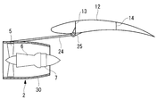
- the thrust generator 1 is installed, for example, below the main wing 12 of the aircraft 10 and generates a thrust that propels the aircraft 10.
- one thrust generator 1 is installed on one main wing 12, and is installed so as to be paired with both main wings 12.
- the thrust generator 1 includes a turbofan engine unit 2 and a motor drive fan unit 3.
- the turbofan engine unit 2 and the motor drive fan unit 3 are provided in parallel.
- the turbofan engine unit 2 is provided on the fuselage 11 side of the aircraft 10, and the motor drive fan unit 3 is provided outside the turbofan engine unit 2.
- the thrust generator 1 is installed on both main wings 12 so that the turbofan engine unit 2 and the motor drive fan unit 3 are symmetrical.
- the motor drive fan part 3 may be provided in the trunk
- the maximum thrust generated by the thrust generator 1 is, for example, 1t to 100t.
- the thrust generator 1 is suspended from the main wing 12 by, for example, one pylon (first support portion) 4.
- the pylon 4 has a structure such as a truss structure.
- the pylon 4 is connected to the substantially central portion of the thrust generating device 1 at one end side, and connected to the structure of the main wing 12 (rib (not shown), front girder 13, rear girder 14, etc.) at the other end side. .
- the pylon 4 can withstand the forces in the vertical direction, the front-rear direction, and the left-right direction applied to the pylon 4.
- the turbofan engine unit 2 includes a fan 5, a core engine unit 6, a generator 7, and the like.
- the turbofan engine unit 2 is divided into a core engine unit 6 provided on the axis of the drive shaft, and a bypass unit around the core engine unit 6 and through which air passing only through the fan 5 flows.
- the core engine unit 6 includes a compressor, a turbine, a combustor, and the like.
- the fan 5, the compressor, the turbine, and the generator 7 are provided on the same drive shaft.
- the combustor of the core engine unit 6 burns fuel and generates high-temperature and high-pressure exhaust gas by combustion.
- the high-temperature and high-pressure exhaust gas is ejected from the nozzle, and the jet of the exhaust gas becomes part of the driving force.
- generated by combustion rotates a turbine.
- the fan 5 and the compressor are rotationally driven by the rotational force of the turbine.
- the compressor compresses air taken in from the air intake port of the turbofan engine unit 2 and sends the compressed air to the combustor.
- the fan 5 is a ducted fan, and the air that has passed through the fan 5 is ejected from the fan nozzle to generate a propulsive force.
- the generator 7 is rotated by the rotational force of the turbine and generates electric power.
- the electric power generated in the generator 7 is supplied to the motor drive fan unit 3 and the like.
- the motor drive fan unit 3 includes a fan 8 and a motor 9.
- the fan 8 and the motor 9 are provided on the same shaft.
- the motor 9 is rotationally driven by electric power supplied from the generator 7 of the turbofan engine unit 2.
- the fan 8 is rotationally driven by the rotational force of the motor 9.
- the fan 8 is a ducted fan, and the air that has passed through the fan 8 is ejected from the fan nozzle to generate a propulsive force.
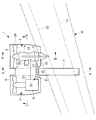
- the generator 7 of the turbofan engine unit 2 and the motor 9 of the motor drive fan unit 3 are connected by a conductive unit 20 through which electricity flows, and power is supplied from the generator 7 to the motor 9.
- the conductive portion 20 has a structure and size that can withstand a current (for example, several thousand A to several tens of thousands A) that flows when the motor driving fan unit 3 exhibits the maximum thrust.
- the conductive portion 20 is constituted by, for example, a metal bus bar 21 and a flexible portion 22, and the bus bar 21 and the flexible portion 22 are connected to each other.
- One end side of the conductive portion 20 is connected to the generator 7, and the other end portion is connected to the motor 9.
- the bus bar 21 is, for example, a metal plate member or a bar member
- the flexible portion 22 is, for example, a mesh member in which metal wire members are meshed, a spring member having elasticity, or the like.
- the flexible part 22 is provided between the two bus bars 21, as shown in FIGS. 2 and 3.
- the flexible portion 22 may be provided at the end of the conductive portion 20, that is, between the generator 7 and the bus bar 21 or between the motor 9 and the bus bar 21.
- a bearing may be used as the flexible portion 22.
- the bearings are arranged so that the electrical connection of the bus bar 21 is maintained even if the relative positions of the turbofan engine unit 2 and the motor drive fan unit 3 change.
- the conductive unit 20 is installed in the housing 30. Thereby, insulation with respect to the conductive part 20 can be ensured without exposing the conductive part 20 to the outside. Further, by using a shielding material (for example, a metal plate member or a net-like member) for the casing 30 or a member (not shown) that covers the conductive portion 20 separately from the casing 30, it is installed in the aircraft 10. Electromagnetic interference to the equipment can be suppressed.
- a shielding material for example, a metal plate member or a net-like member
- the conductive unit 20 is not installed around the main wing 12 or the like, and the turbofan engine unit 2 and the motor drive fan are disposed. It is arranged in a straight line with the portion 3 at a short distance. Therefore, since the length of the conductive portion 20 is short, the weight of the conductive portion 20 can be reduced, which contributes to a reduction in the weight of the entire aircraft 10 and can reduce power loss. Furthermore, electromagnetic waves generated when electricity flows through the conductive portion 20 are reduced, and electromagnetic interference given to equipment installed in the aircraft 10 can be suppressed.
- the turbofan engine unit 2 and the motor drive fan unit 3 are integrated.
- the turbofan engine unit 2 and the motor drive fan unit 3 are individually transported and installed. Rather than being treated as a whole.
- the turbofan engine unit 2 and the motor drive fan unit 3 are accommodated in, for example, a single casing 30 that surrounds them.
- the conductive unit 20 is installed in the same housing 30 in which the turbofan engine unit 2 and the motor drive fan unit 3 are accommodated.
- the turbo fan engine part 2 and the motor drive fan part 3 can be easily handled as an integrated object, and the influence of electromagnetic waves to the outside can be reduced by the shielding effect of the housing 30.
- a partition plate may be provided between the turbofan engine unit 2 and the motor drive fan unit 3. Thereby, the spread of fire from the turbofan engine part 2 to the motor drive fan part 3 can be prevented, and the strength of the thrust generator 1 can be improved.
- the housing 30 is a plate made of, for example, metal or carbon fiber reinforced plastic.
- a strut (second support part) 24 is provided between the turbofan engine part 2 and the main wing 12 of the thrust generator 1 as shown in FIGS.
- the strut 24 is parallel to the axis of the turbofan engine unit 2, one end is connected to the turbofan engine unit 2, and the other end is connected to the structure of the main wing 12 (rib, front girder 13, etc.) via a mounting bracket 25. ).
- the strut 24 is a structure that can withstand a tensile load, and is, for example, a wire member.
- the turbo fan engine unit 2 When the motor driven fan unit 3 is stopped and only the turbo fan engine unit 2 is driven, or when the turbo fan engine unit 2 has a larger thrust than the motor driven fan unit 3, the turbo fan engine unit 2 is used as the motor driven fan unit.
- the pylon 4 is subjected to a moment in the yawing direction because it tends to come out ahead of 3. By providing the strut 24 and bearing a tensile load, deformation of the pylon 4 can be suppressed.
- the thrust control device 26 is provided in the housing 30 and adjusts the propulsive force of each of the turbofan engine unit 2 and the motor drive fan unit 3.
- the thrust control device 26 is connected to the generator 7 and the motor 9 via the control line 27, and transmits and receives control signals between the generator 7 and the motor 9.
- the thrust control device 26 maximizes the total propulsive force of the turbofan engine unit 2 and the motor drive fan unit 3 when the aircraft 10 takes off.
- the thrust control device 26 preferentially reduces the thrust of the turbofan engine unit 2.
- the amount of air passing through the motor-driven fan unit 3 is relatively larger than the amount of air passing through the turbofan engine unit 2, and the bypass ratio during cruising is larger than the bypass ratio during takeoff. .
- the thrust generating device 1 when the thrust generating device 1 is driven, air is ejected from the motor-driven fan unit 3, so that the turbo fan is compared with a case where only a conventional turbo fan engine is mounted.
- the amount of air that does not pass through the core engine part 6 of the engine part 2 increases.
- the bypass ratio can be increased as compared with the conventional one while maintaining the clearance with the ground.
- the bypass ratio is increased, fuel efficiency can be improved and noise can be reduced.
- the same bypass ratio as that of the conventional turbofan engine only needs to be realized, the amount of air that does not pass through the core engine unit 6 of the turbofan engine unit 2 can be supplemented by the motor drive fan unit 3.
- the height of the entire generator 1 can be suppressed.
- the bypass ratio can be made variable. Therefore, it is possible to fly with an optimum bypass ratio according to the flight state such as takeoff, cruise, and landing.
- the thrust generator 1 is provided with the turbofan engine unit 2 and the motor-driven fan unit 3 so that the thrust generator 1 is installed on the aircraft 10 as compared with the case where each unit is installed individually. Work and the structure of the aircraft 10 can be simplified. That is, when one thrust generator 1 is installed on one main wing 12, only one pylon needs to be attached to the main wing 12, and installation work is performed at one location on each wing. It is also possible to remove the turbofan engine from an existing aircraft in which the turbofan engine is installed and replace it with the thrust generator 1 according to the present embodiment. In this case, it is necessary to replace the pylon, but it is not necessary to significantly change the reinforcing structure of the main wing. In addition, according to the present embodiment, since the strut 24 is provided between the turbofan engine unit 2 and the main wing 12, the load in the yawing direction applied to the pylon 4 can be reduced.
- the turbofan engine unit 2 and the motor drive fan unit 3 are arranged close to each other, and the conductive unit 20 is arranged linearly and at a short distance, so that the structure is simple. The weight and power loss can be reduced, and the influence of electromagnetic interference can be reduced. Further, by installing not only the bus bar 21 but also the flexible portion 22 as the conductive portion 20, damage to the conductive portion 20 and the like can be avoided.
Landscapes
- Engineering & Computer Science (AREA)
- Aviation & Aerospace Engineering (AREA)
- Chemical & Material Sciences (AREA)
- Combustion & Propulsion (AREA)
- Mechanical Engineering (AREA)
- General Engineering & Computer Science (AREA)
- Structures Of Non-Positive Displacement Pumps (AREA)
- Connection Of Motors, Electrical Generators, Mechanical Devices, And The Like (AREA)
Abstract
Description
推力発生装置1は、図1に示すように、例えば、航空機10の主翼12の下方に設置され、航空機10を推進させる推力を発生する。推力発生装置1は、片方の主翼12に例えば1台設置され、両方の主翼12で対となるように設置される。推力発生装置1は、ターボファンエンジン部2と、モータ駆動ファン部3とを有する。ターボファンエンジン部2と、モータ駆動ファン部3は、並列して設けられる。
発電機7は、タービンの回転力によって回転し、電力を発生する。発電機7において発生した電力は、モータ駆動ファン部3等に供給される。
モータ9は、ターボファンエンジン部2の発電機7から供給された電力によって、回転駆動する。モータ9の回転力によって、ファン8が回転駆動する。ファン8は、ダクテッドファンであり、ファン8を通過した空気は、ファンノズルから噴出され、推進力を発生させる。
また、ターボファンエンジンが設置されている既存の航空機に対して、ターボファンエンジンを取り外し、本実施形態に係る推力発生装置1に置き換えることも可能である。この場合、パイロンも取り換える必要があるが、主翼の補強構造の大幅な変更が不要である。
また、本実施形態によれば、ターボファンエンジン部2と主翼12の間にストラット24が設けられるため、パイロン4にかかるヨーイング方向の荷重を低減できる。
2 ターボファンエンジン部
3 モータ駆動ファン部
4 パイロン(第1支持部)
5 ファン(第1ファン)
6 コアエンジン部
7 発電機(発電部)
8 ファン(第2ファン)
9 モータ(電動部)
10 航空機
11 胴体
12 主翼
13 前桁
14 後桁
20 導電部
21 バスバー
22 柔軟部
24 ストラット(第2支持部)
26 推力制御装置(制御装置)
27 制御線
30 筐体
Claims (6)
- 駆動軸の回転力によって電力を発生する発電部を有し、燃料が燃焼されて生成されるガスによって、前記駆動軸に設けられた第1ファンを駆動する第1推進部と、
前記発電部から供給された電力によって駆動する電動部を有し、前記第1推進部と並列に設けられて、前記電動部によって第2ファンを駆動する第2推進部と、
前記発電部と前記電動部を結び、前記発電部で発生した電力を前記電動部に供給する導電部と、
を備え、
前記第1推進部と前記第2推進部は、一体化されており、
前記導電部は、前記第1推進部と前記第2推進部の間に配置されている推力発生装置。 - 前記第1推進部と前記第2推進部が一つの筐体に収容されている請求項1に記載の推力発生装置。
- 前記第1推進部と前記第2推進部の推力を調整する制御部を更に備える請求項1又は2に記載の推力発生装置。
- 前記導電部は、バスバーと、前記バスバーに接続され前記バスバーの位置変化を吸収する柔軟部とを有する請求項1から3のいずれか1項に記載の推力発生装置。
- 請求項1から4のいずれか1項に記載の推力発生装置と、
前記推力発生装置を吊り下げて支持する一つの第1支持部と、
を備える航空機。 - 前記第1推進部と主翼とに結合され、引張荷重を負担する第2支持部を更に備える請求項5に記載の航空機。
Priority Applications (6)
| Application Number | Priority Date | Filing Date | Title |
|---|---|---|---|
| BR112017018148-7A BR112017018148A2 (ja) | 2015-02-27 | 2016-02-24 | A thrust generator and an airplane |
| CN201680010192.1A CN107249981A (zh) | 2015-02-27 | 2016-02-24 | 推力产生装置及航空机 |
| CA2977487A CA2977487C (en) | 2015-02-27 | 2016-02-24 | Thrust force generation device and aircraft |
| US15/552,699 US10752369B2 (en) | 2015-02-27 | 2016-02-24 | Thrust force generation device and aircraft |
| EP16755514.3A EP3243753B1 (en) | 2015-02-27 | 2016-02-24 | Thrust force generation device and aircraft |
| RU2017128641A RU2662596C1 (ru) | 2015-02-27 | 2016-02-24 | Устройство для формирования силы тяги и летательный аппарат |
Applications Claiming Priority (2)
| Application Number | Priority Date | Filing Date | Title |
|---|---|---|---|
| JP2015038282A JP6437347B2 (ja) | 2015-02-27 | 2015-02-27 | 推力発生装置及び航空機 |
| JP2015-038282 | 2015-02-27 |
Publications (1)
| Publication Number | Publication Date |
|---|---|
| WO2016136770A1 true WO2016136770A1 (ja) | 2016-09-01 |
Family
ID=56788927
Family Applications (1)
| Application Number | Title | Priority Date | Filing Date |
|---|---|---|---|
| PCT/JP2016/055336 Ceased WO2016136770A1 (ja) | 2015-02-27 | 2016-02-24 | 推力発生装置及び航空機 |
Country Status (8)
| Country | Link |
|---|---|
| US (1) | US10752369B2 (ja) |
| EP (1) | EP3243753B1 (ja) |
| JP (1) | JP6437347B2 (ja) |
| CN (1) | CN107249981A (ja) |
| BR (1) | BR112017018148A2 (ja) |
| CA (1) | CA2977487C (ja) |
| RU (1) | RU2662596C1 (ja) |
| WO (1) | WO2016136770A1 (ja) |
Cited By (3)
| Publication number | Priority date | Publication date | Assignee | Title |
|---|---|---|---|---|
| CN108252807A (zh) * | 2016-12-28 | 2018-07-06 | 中国航发商用航空发动机有限责任公司 | 涡轮电动式的发动机推进系统 |
| CN108408061A (zh) * | 2017-02-10 | 2018-08-17 | 通用电气公司 | 用于飞行器的推进系统 |
| JP2024507254A (ja) * | 2021-02-19 | 2024-02-16 | リリウム ゲーエムベーハー | 航空機エンジン |
Families Citing this family (23)
| Publication number | Priority date | Publication date | Assignee | Title |
|---|---|---|---|---|
| GB2544625B (en) * | 2015-10-05 | 2021-09-22 | Safran Aircraft Engines | Aircraft with a propulsion unit with offset fan |
| US10633104B2 (en) * | 2017-05-17 | 2020-04-28 | General Electric Company | Hybrid-electric propulsion system for an aircraft |
| US10676199B2 (en) * | 2017-06-12 | 2020-06-09 | General Electric Company | Propulsion system for an aircraft |
| US11008111B2 (en) * | 2017-06-26 | 2021-05-18 | General Electric Company | Propulsion system for an aircraft |
| GB201807770D0 (en) | 2018-05-14 | 2018-06-27 | Rolls Royce Plc | Electric ducted fan |
| GB201807769D0 (en) * | 2018-05-14 | 2018-06-27 | Rolls Royce Plc | Electric ducted fan |
| GB201811401D0 (en) * | 2018-07-12 | 2018-08-29 | Rolls Royce Plc | Supersonic aircraft propulsion installation |
| US11097849B2 (en) | 2018-09-10 | 2021-08-24 | General Electric Company | Aircraft having an aft engine |
| GB201820919D0 (en) | 2018-12-21 | 2019-02-06 | Rolls Royce Plc | Turbine engine |
| US11204037B2 (en) | 2018-12-21 | 2021-12-21 | Rolls-Royce Plc | Turbine engine |
| GB201820924D0 (en) | 2018-12-21 | 2019-02-06 | Rolls Royce Plc | Turbine engine |
| GB201820930D0 (en) * | 2018-12-21 | 2019-02-06 | Rolls Royce Plc | Turbine engine |
| GB201820925D0 (en) | 2018-12-21 | 2019-02-06 | Rolls Royce Plc | Turbine engine |
| EP3931094A4 (en) * | 2019-03-01 | 2022-11-16 | United Technologies Advanced Projects, Inc. | ELECTRIC PROPULSION SYSTEM FOR AIRCRAFT WITH A HYBRID ELECTRIC PROPULSION SYSTEM |
| US11427344B2 (en) | 2019-03-01 | 2022-08-30 | Pratt & Whitney Canada Corp. | Cooling system configurations for an aircraft having hybrid-electric propulsion system |
| US11697505B2 (en) * | 2019-03-01 | 2023-07-11 | Pratt & Whitney Canada Corp. | Distributed propulsion configurations for aircraft having mixed drive systems |
| US11912422B2 (en) * | 2019-08-26 | 2024-02-27 | Hamilton Sundstrand Corporation | Hybrid electric aircraft and powerplant arrangements |
| US20210347490A1 (en) * | 2020-05-07 | 2021-11-11 | Gulfstream Aerospace Corporation | Hybrid jet electric aircraft |
| US11852024B2 (en) | 2020-12-18 | 2023-12-26 | Ge Aviation Systems Llc | Electrical strut for a turbine engine |
| CN114215658A (zh) * | 2021-11-29 | 2022-03-22 | 中国航发沈阳发动机研究所 | 一种具有大范围涵道比调节能力的推进系统 |
| US11691742B1 (en) | 2022-02-04 | 2023-07-04 | Pratt & Whitney Canada Corp | Containment zone for an electric machine in a hybrid powerplant for an aircraft |
| US20240208663A1 (en) * | 2022-12-23 | 2024-06-27 | Pratt & Whitney Canada Corp. | Hybrid aircraft propulsion system with remotely located electric machine |
| US12291347B2 (en) | 2023-07-31 | 2025-05-06 | Pratt & Whitney Canada Corp. | Containment zone for an electric machine in a hybrid powerplant for an aircraft |
Citations (9)
| Publication number | Priority date | Publication date | Assignee | Title |
|---|---|---|---|---|
| JP2006205755A (ja) * | 2005-01-25 | 2006-08-10 | Japan Aerospace Exploration Agency | 航空機用推進システム |
| US20090121073A1 (en) * | 2006-04-03 | 2009-05-14 | The Boeing Company | Aircraft having a jet engine, an adjustable aft nozzle, and an electric vertical fan |
| US20130062455A1 (en) * | 2005-04-20 | 2013-03-14 | Richard H. Lugg | Hybrid jet/electric vtol aircraft |
| US20130094963A1 (en) * | 2011-10-13 | 2013-04-18 | Rolls-Royce Plc | Distributed propulsion system and method of control |
| JP2013099158A (ja) * | 2011-11-02 | 2013-05-20 | Sumitomo Electric Ind Ltd | インバータ装置用コネクタ |
| JP5453620B2 (ja) * | 2008-10-08 | 2014-03-26 | ザ インベンション サイエンス ファンド ワン,リミテッド ライアビリティー カンパニー | 少なくとも1つの独立して回転可能なプロペラ/ファンを備えるハイブリッド型推進機関 |
| US20140360206A1 (en) * | 2013-04-24 | 2014-12-11 | Rolls-Royce Plc | Aircraft powerplant |
| US20140367510A1 (en) * | 2013-06-14 | 2014-12-18 | Airbus | Aircraft with electric propulsion means |
| US20150013306A1 (en) * | 2010-11-19 | 2015-01-15 | Rudolph Allen SHELLEY | Hybrid Gas Turbine Propulsion System |
Family Cites Families (27)
| Publication number | Priority date | Publication date | Assignee | Title |
|---|---|---|---|---|
| RU2122965C1 (ru) * | 1996-08-12 | 1998-12-10 | Кормилицин Юрий Николаевич | Многоцелевой самолет-амфибия |
| CN1200343A (zh) * | 1997-05-24 | 1998-12-02 | 王克西 | 可脱险的运客飞机及作战机的垂直起落 |
| US6247668B1 (en) * | 1999-07-15 | 2001-06-19 | The Boeing Company | Auxiliary power and thrust unit |
| US10443139B2 (en) * | 2003-09-05 | 2019-10-15 | Brilliant Light Power, Inc. | Electrical power generation systems and methods regarding same |
| CN101146574A (zh) | 2005-02-06 | 2008-03-19 | 超形态公司 | 非热的声波组织改变 |
| FR2902406B1 (fr) * | 2006-06-20 | 2008-07-18 | Airbus France Sas | Carenage pour mat de suspension d'un turbomoteur a une aile d'aeronef |
| US20080184906A1 (en) * | 2007-02-07 | 2008-08-07 | Kejha Joseph B | Long range hybrid electric airplane |
| US8049460B2 (en) * | 2007-07-18 | 2011-11-01 | Tesla Motors, Inc. | Voltage dividing vehicle heater system and method |
| US8205825B2 (en) * | 2008-02-27 | 2012-06-26 | Spirit Aerosystems, Inc. | Engine pylon made from composite material |
| DE102008011643A1 (de) | 2008-02-28 | 2009-09-03 | Rolls-Royce Deutschland Ltd & Co Kg | Flugzeugantriebseinheit mit Multi-Fan-Ausgestaltung |
| GB0903423D0 (en) * | 2009-03-02 | 2009-04-08 | Rolls Royce Plc | Variable drive gas turbine engine |
| FR2943039B1 (fr) * | 2009-03-12 | 2012-09-28 | Airbus France | Avion a empennage queue-de-morue et moteur arriere. |
| US8294316B2 (en) * | 2009-07-28 | 2012-10-23 | Rolls-Royce North American Technologies, Inc. | Electrical power generation apparatus for contra-rotating open-rotor aircraft propulsion system |
| US20110154805A1 (en) * | 2009-12-31 | 2011-06-30 | Craig Heathco | Power augmentation system for an engine powered air vehicle |
| US20120128493A1 (en) * | 2010-11-19 | 2012-05-24 | Shelley Rudolph Allen | Hybrid free-air gas turbine engine |
| US20120209456A1 (en) * | 2011-02-15 | 2012-08-16 | Government Of The United States, As Represented By The Secretary Of The Air Force | Parallel Hybrid-Electric Propulsion Systems for Unmanned Aircraft |
| US9637241B2 (en) * | 2012-03-16 | 2017-05-02 | The Boeing Company | Engine mounting system for an aircraft |
| DE102012209803A1 (de) * | 2012-06-12 | 2013-12-12 | Siemens Aktiengesellschaft | Verfahren zum Bereitstellen einer vorbestimmten Antriebscharakteristik in einem Flugzeug und zugehörige Antriebsvorrichtung |
| FR2994707B1 (fr) * | 2012-08-21 | 2018-04-06 | Snecma | Turbomachine hybride a helices contrarotatives |
| US9458766B2 (en) * | 2012-12-24 | 2016-10-04 | United Technologies Corporation | Blind installation pin for a gas turbine engine mount |
| ES2500015B1 (es) * | 2013-02-28 | 2015-06-23 | Axter Aerospace S.L. | Sistema de potencia auxiliar eléctrico para aeronaves de motor de pistón |
| CA2902461C (en) * | 2013-03-14 | 2021-04-06 | Rolls-Royce Corporation | Hybrid turbo electric aero-propulsion system control |
| US9404507B2 (en) * | 2013-04-15 | 2016-08-02 | Mra Systems, Inc. | Inner cowl structure for aircraft turbine engine |
| RU2534676C1 (ru) * | 2013-05-27 | 2014-12-10 | Дмитрий Сергеевич Дуров | Криогенный турбоэлектрический самолет короткого взлета и посадки |
| US9771863B2 (en) * | 2014-02-07 | 2017-09-26 | United Technologies Corporation | Gas turbine engine with embedded distributed fans |
| EP2998557B1 (en) | 2014-09-17 | 2017-07-12 | Airbus Operations, S.L. | Aircraft hybrid engine |
| US20180002025A1 (en) * | 2016-07-01 | 2018-01-04 | United Technologies Corporation | Aircraft including parallel hybrid gas turbine electric propulsion system |
-
2015
- 2015-02-27 JP JP2015038282A patent/JP6437347B2/ja active Active
-
2016
- 2016-02-24 BR BR112017018148-7A patent/BR112017018148A2/ja not_active Application Discontinuation
- 2016-02-24 US US15/552,699 patent/US10752369B2/en active Active
- 2016-02-24 WO PCT/JP2016/055336 patent/WO2016136770A1/ja not_active Ceased
- 2016-02-24 RU RU2017128641A patent/RU2662596C1/ru active
- 2016-02-24 CA CA2977487A patent/CA2977487C/en not_active Expired - Fee Related
- 2016-02-24 CN CN201680010192.1A patent/CN107249981A/zh active Pending
- 2016-02-24 EP EP16755514.3A patent/EP3243753B1/en not_active Not-in-force
Patent Citations (9)
| Publication number | Priority date | Publication date | Assignee | Title |
|---|---|---|---|---|
| JP2006205755A (ja) * | 2005-01-25 | 2006-08-10 | Japan Aerospace Exploration Agency | 航空機用推進システム |
| US20130062455A1 (en) * | 2005-04-20 | 2013-03-14 | Richard H. Lugg | Hybrid jet/electric vtol aircraft |
| US20090121073A1 (en) * | 2006-04-03 | 2009-05-14 | The Boeing Company | Aircraft having a jet engine, an adjustable aft nozzle, and an electric vertical fan |
| JP5453620B2 (ja) * | 2008-10-08 | 2014-03-26 | ザ インベンション サイエンス ファンド ワン,リミテッド ライアビリティー カンパニー | 少なくとも1つの独立して回転可能なプロペラ/ファンを備えるハイブリッド型推進機関 |
| US20150013306A1 (en) * | 2010-11-19 | 2015-01-15 | Rudolph Allen SHELLEY | Hybrid Gas Turbine Propulsion System |
| US20130094963A1 (en) * | 2011-10-13 | 2013-04-18 | Rolls-Royce Plc | Distributed propulsion system and method of control |
| JP2013099158A (ja) * | 2011-11-02 | 2013-05-20 | Sumitomo Electric Ind Ltd | インバータ装置用コネクタ |
| US20140360206A1 (en) * | 2013-04-24 | 2014-12-11 | Rolls-Royce Plc | Aircraft powerplant |
| US20140367510A1 (en) * | 2013-06-14 | 2014-12-18 | Airbus | Aircraft with electric propulsion means |
Non-Patent Citations (1)
| Title |
|---|
| See also references of EP3243753A4 * |
Cited By (5)
| Publication number | Priority date | Publication date | Assignee | Title |
|---|---|---|---|---|
| CN108252807A (zh) * | 2016-12-28 | 2018-07-06 | 中国航发商用航空发动机有限责任公司 | 涡轮电动式的发动机推进系统 |
| CN108252807B (zh) * | 2016-12-28 | 2019-12-17 | 中国航发商用航空发动机有限责任公司 | 涡轮电动式的发动机推进系统 |
| CN108408061A (zh) * | 2017-02-10 | 2018-08-17 | 通用电气公司 | 用于飞行器的推进系统 |
| JP2024507254A (ja) * | 2021-02-19 | 2024-02-16 | リリウム ゲーエムベーハー | 航空機エンジン |
| JP7576184B2 (ja) | 2021-02-19 | 2024-10-30 | リリウム ゲーエムベーハー | 航空機エンジン |
Also Published As
| Publication number | Publication date |
|---|---|
| EP3243753A1 (en) | 2017-11-15 |
| CA2977487A1 (en) | 2016-09-01 |
| BR112017018148A2 (ja) | 2018-04-10 |
| US10752369B2 (en) | 2020-08-25 |
| US20180044028A1 (en) | 2018-02-15 |
| EP3243753A4 (en) | 2017-12-20 |
| CA2977487C (en) | 2019-08-13 |
| JP2016159692A (ja) | 2016-09-05 |
| JP6437347B2 (ja) | 2018-12-12 |
| EP3243753B1 (en) | 2020-07-29 |
| RU2662596C1 (ru) | 2018-07-26 |
| CN107249981A (zh) | 2017-10-13 |
Similar Documents
| Publication | Publication Date | Title |
|---|---|---|
| JP6437347B2 (ja) | 推力発生装置及び航空機 | |
| US20220234746A1 (en) | Gas-Electric Propulsion System for an Aircraft | |
| CN102666279B (zh) | 涡轮喷气发动机中的用于安装附件箱的中间箱体 | |
| EP3216698B1 (en) | Propulsion system for an aircraft | |
| JP5224823B2 (ja) | 推進装置 | |
| CN111491859B (zh) | 具有反扭矩系统的直升机 | |
| JP6265609B2 (ja) | 航空機のエンジン搭載システム | |
| EP2844556B1 (de) | Hybridflugzeug | |
| US20230406483A1 (en) | Acoustic noise suppressing ducted fan propulsor mounting arrangement and treatments | |
| US20110016882A1 (en) | Electrical Cable Shroud | |
| US20130092789A1 (en) | Hybrid drive for helicopters | |
| US9663239B2 (en) | Clocked thrust reversers | |
| CN105000187B (zh) | 用于飞行器的组件和飞行器 | |
| EP2278203A1 (en) | Integrated electrical cable support | |
| CN107428416A (zh) | 旋转涵道风扇(rdf)推进系统 | |
| US8907595B2 (en) | Aircraft engine nacelle comprising a mobile cowl moved by electric motors | |
| GB2434836A (en) | A mounting system for use in mounting a gas turbine engine | |
| BR102012032396A2 (pt) | Conjunto de mastro de motor, e, sistema de motor de turbina de gás | |
| EP3034395B1 (en) | Aircraft boundary layer removal with auxilliary power unit suction | |
| JP2008545572A (ja) | 航空機用エンジンユニット | |
| US20200140107A1 (en) | Engine mounted aircraft gearbox disposed in pylon | |
| US12545427B2 (en) | Ducted supplemental power unit of aircraft | |
| RU2624488C1 (ru) | Электролет маноян |
Legal Events
| Date | Code | Title | Description |
|---|---|---|---|
| 121 | Ep: the epo has been informed by wipo that ep was designated in this application |
Ref document number: 16755514 Country of ref document: EP Kind code of ref document: A1 |
|
| REEP | Request for entry into the european phase |
Ref document number: 2016755514 Country of ref document: EP |
|
| ENP | Entry into the national phase |
Ref document number: 2977487 Country of ref document: CA |
|
| WWE | Wipo information: entry into national phase |
Ref document number: 15552699 Country of ref document: US |
|
| NENP | Non-entry into the national phase |
Ref country code: DE |
|
| REG | Reference to national code |
Ref country code: BR Ref legal event code: B01A Ref document number: 112017018148 Country of ref document: BR |
|
| ENP | Entry into the national phase |
Ref document number: 2017128641 Country of ref document: RU Kind code of ref document: A |
|
| ENP | Entry into the national phase |
Ref document number: 112017018148 Country of ref document: BR Kind code of ref document: A2 Effective date: 20170824 |