WO2016136788A1 - 電池劣化診断方法および電池劣化診断装置 - Google Patents
電池劣化診断方法および電池劣化診断装置 Download PDFInfo
- Publication number
- WO2016136788A1 WO2016136788A1 PCT/JP2016/055374 JP2016055374W WO2016136788A1 WO 2016136788 A1 WO2016136788 A1 WO 2016136788A1 JP 2016055374 W JP2016055374 W JP 2016055374W WO 2016136788 A1 WO2016136788 A1 WO 2016136788A1
- Authority
- WO
- WIPO (PCT)
- Prior art keywords
- battery
- voltage
- charging
- secondary battery
- deterioration
- Prior art date
- Legal status (The legal status is an assumption and is not a legal conclusion. Google has not performed a legal analysis and makes no representation as to the accuracy of the status listed.)
- Ceased
Links
Images





Classifications
-
- G—PHYSICS
- G01—MEASURING; TESTING
- G01R—MEASURING ELECTRIC VARIABLES; MEASURING MAGNETIC VARIABLES
- G01R31/00—Arrangements for testing electric properties; Arrangements for locating electric faults; Arrangements for electrical testing characterised by what is being tested not provided for elsewhere
- G01R31/36—Arrangements for testing, measuring or monitoring the electrical condition of accumulators or electric batteries, e.g. capacity or state of charge [SoC]
- G01R31/392—Determining battery ageing or deterioration, e.g. state of health
-
- H—ELECTRICITY
- H01—ELECTRIC ELEMENTS
- H01M—PROCESSES OR MEANS, e.g. BATTERIES, FOR THE DIRECT CONVERSION OF CHEMICAL ENERGY INTO ELECTRICAL ENERGY
- H01M10/00—Secondary cells; Manufacture thereof
- H01M10/05—Accumulators with non-aqueous electrolyte
- H01M10/052—Li-accumulators
- H01M10/0525—Rocking-chair batteries, i.e. batteries with lithium insertion or intercalation in both electrodes; Lithium-ion batteries
-
- H—ELECTRICITY
- H01—ELECTRIC ELEMENTS
- H01M—PROCESSES OR MEANS, e.g. BATTERIES, FOR THE DIRECT CONVERSION OF CHEMICAL ENERGY INTO ELECTRICAL ENERGY
- H01M10/00—Secondary cells; Manufacture thereof
- H01M10/42—Methods or arrangements for servicing or maintenance of secondary cells or secondary half-cells
-
- H—ELECTRICITY
- H01—ELECTRIC ELEMENTS
- H01M—PROCESSES OR MEANS, e.g. BATTERIES, FOR THE DIRECT CONVERSION OF CHEMICAL ENERGY INTO ELECTRICAL ENERGY
- H01M10/00—Secondary cells; Manufacture thereof
- H01M10/42—Methods or arrangements for servicing or maintenance of secondary cells or secondary half-cells
- H01M10/48—Accumulators combined with arrangements for measuring, testing or indicating the condition of cells, e.g. the level or density of the electrolyte
-
- H—ELECTRICITY
- H01—ELECTRIC ELEMENTS
- H01M—PROCESSES OR MEANS, e.g. BATTERIES, FOR THE DIRECT CONVERSION OF CHEMICAL ENERGY INTO ELECTRICAL ENERGY
- H01M10/00—Secondary cells; Manufacture thereof
- H01M10/42—Methods or arrangements for servicing or maintenance of secondary cells or secondary half-cells
- H01M10/48—Accumulators combined with arrangements for measuring, testing or indicating the condition of cells, e.g. the level or density of the electrolyte
- H01M10/486—Accumulators combined with arrangements for measuring, testing or indicating the condition of cells, e.g. the level or density of the electrolyte for measuring temperature
-
- H—ELECTRICITY
- H02—GENERATION; CONVERSION OR DISTRIBUTION OF ELECTRIC POWER
- H02J—ELECTRIC POWER NETWORKS; CIRCUIT ARRANGEMENTS OR SYSTEMS FOR SUPPLYING OR DISTRIBUTING ELECTRIC POWER; SYSTEMS FOR STORING ELECTRIC ENERGY
- H02J7/00—Circuit arrangements for charging or discharging batteries or for supplying loads from batteries
-
- G—PHYSICS
- G01—MEASURING; TESTING
- G01R—MEASURING ELECTRIC VARIABLES; MEASURING MAGNETIC VARIABLES
- G01R31/00—Arrangements for testing electric properties; Arrangements for locating electric faults; Arrangements for electrical testing characterised by what is being tested not provided for elsewhere
- G01R31/36—Arrangements for testing, measuring or monitoring the electrical condition of accumulators or electric batteries, e.g. capacity or state of charge [SoC]
- G01R31/367—Software therefor, e.g. for battery testing using modelling or look-up tables
-
- G—PHYSICS
- G01—MEASURING; TESTING
- G01R—MEASURING ELECTRIC VARIABLES; MEASURING MAGNETIC VARIABLES
- G01R31/00—Arrangements for testing electric properties; Arrangements for locating electric faults; Arrangements for electrical testing characterised by what is being tested not provided for elsewhere
- G01R31/36—Arrangements for testing, measuring or monitoring the electrical condition of accumulators or electric batteries, e.g. capacity or state of charge [SoC]
- G01R31/374—Arrangements for testing, measuring or monitoring the electrical condition of accumulators or electric batteries, e.g. capacity or state of charge [SoC] with means for correcting the measurement for temperature or ageing
-
- G—PHYSICS
- G01—MEASURING; TESTING
- G01R—MEASURING ELECTRIC VARIABLES; MEASURING MAGNETIC VARIABLES
- G01R31/00—Arrangements for testing electric properties; Arrangements for locating electric faults; Arrangements for electrical testing characterised by what is being tested not provided for elsewhere
- G01R31/36—Arrangements for testing, measuring or monitoring the electrical condition of accumulators or electric batteries, e.g. capacity or state of charge [SoC]
- G01R31/378—Arrangements for testing, measuring or monitoring the electrical condition of accumulators or electric batteries, e.g. capacity or state of charge [SoC] specially adapted for the type of battery or accumulator
-
- G—PHYSICS
- G01—MEASURING; TESTING
- G01R—MEASURING ELECTRIC VARIABLES; MEASURING MAGNETIC VARIABLES
- G01R31/00—Arrangements for testing electric properties; Arrangements for locating electric faults; Arrangements for electrical testing characterised by what is being tested not provided for elsewhere
- G01R31/36—Arrangements for testing, measuring or monitoring the electrical condition of accumulators or electric batteries, e.g. capacity or state of charge [SoC]
- G01R31/385—Arrangements for measuring battery or accumulator variables
- G01R31/387—Determining ampere-hour charge capacity or SoC
- G01R31/388—Determining ampere-hour charge capacity or SoC involving voltage measurements
-
- G—PHYSICS
- G01—MEASURING; TESTING
- G01R—MEASURING ELECTRIC VARIABLES; MEASURING MAGNETIC VARIABLES
- G01R31/00—Arrangements for testing electric properties; Arrangements for locating electric faults; Arrangements for electrical testing characterised by what is being tested not provided for elsewhere
- G01R31/36—Arrangements for testing, measuring or monitoring the electrical condition of accumulators or electric batteries, e.g. capacity or state of charge [SoC]
- G01R31/389—Measuring internal impedance, internal conductance or related variables
Definitions
- the present invention relates to a battery deterioration diagnosis method and a battery deterioration diagnosis device for diagnosing battery deterioration of a secondary battery.
- Secondary batteries especially lithium-ion secondary batteries, have a low internal impedance, so there is a risk of causing a large current in the event of a short circuit and causing a fire. For this reason, in the lithium ion secondary battery, the voltage range at the time of charging / discharging is strictly defined, and charging / discharging control is performed by a protective device that monitors voltage, current, surface temperature, etc., and abnormal operation is suppressed. .
- the characteristics of a lithium ion secondary battery also depend on battery deterioration.
- the protection device cannot diagnose the battery deterioration of the lithium ion secondary battery, there are a number of accidents such as the protection device not functioning and the lithium ion secondary battery firing. Therefore, in order to suppress accidents due to battery deterioration, it is necessary to diagnose battery deterioration and replace the lithium ion secondary battery at an appropriate time.
- a battery deterioration diagnosis method using a dedicated device by an AC superposition method As a method of diagnosing battery deterioration of a lithium ion secondary battery, a battery deterioration diagnosis method using a dedicated device by an AC superposition method is known.
- this battery deterioration diagnosis method has low versatility because the dedicated device is expensive and it is necessary to remove the lithium ion secondary battery from the used device and connect it to the dedicated device.
- Another method for diagnosing battery deterioration of a lithium ion secondary battery is to derive internal impedance from a voltage / current waveform during operation of the lithium ion secondary battery and diagnose battery deterioration based on the internal impedance.
- a degradation diagnosis method is known (for example, see Non-Patent Document 1).
- this battery deterioration diagnosis method has a large dependency on the charging rate (SOC) and has a problem in accuracy and the like, and has not been put into practical use.
- the present invention has been made in view of the above circumstances, and an object of the present invention is to provide a battery deterioration diagnosis method and a battery deterioration diagnosis apparatus that are relatively inexpensive and practical.
- a battery deterioration diagnosis method is: A battery deterioration diagnosis method for diagnosing battery deterioration of a secondary battery having transient characteristics, A charging step of charging the secondary battery; After completion of the charging, in the process where the voltage between the battery terminals of the secondary battery converges to the battery internal voltage of the secondary battery, the potential difference obtained by subtracting the battery internal voltage from the voltage between the battery terminals is integrated, and the potential difference A calculation step for calculating an integral value of And a diagnostic step of diagnosing battery deterioration of the secondary battery based on the integrated value.
- the battery deterioration diagnosis method is as follows.
- the integral value is corrected by a correction function that increases exponentially as the ambient temperature of the secondary battery increases.
- diagnosis step it is preferable to diagnose battery deterioration of the secondary battery based on the integrated value after correction.
- a battery deterioration diagnosis device includes: A battery deterioration diagnosis device for diagnosing battery deterioration of a secondary battery having transient characteristics, After completion of charging of the secondary battery, in the process where the voltage between the battery terminals of the secondary battery converges to the battery internal voltage of the secondary battery, the potential difference obtained by subtracting the battery internal voltage from the voltage between the battery terminals is integrated. And an arithmetic unit for calculating an integral value of the potential difference; A storage unit storing first data relating to battery degradation characteristics of the integrated value; And a diagnosis unit that diagnoses battery deterioration of the secondary battery based on the integral value calculated by the calculation unit and the first data stored in the storage unit.
- the storage unit stores a correction function that increases exponentially as the ambient temperature of the secondary battery increases, and second data related to the battery deterioration characteristics of the integrated value corrected by the correction function. And The calculation unit corrects the integral value by the correction function, It is preferable that the diagnosis unit diagnoses battery deterioration of the secondary battery based on the corrected integrated value and the second data.
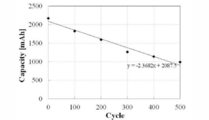
- FIG. 1 is a schematic configuration diagram of a battery deterioration diagnosis device according to the present invention. It is a cycle characteristic figure of the battery discharge capacity of a lithium ion secondary battery. It is an equivalent circuit diagram of a lithium ion secondary battery. It is a voltage-current waveform diagram of a lithium ion secondary battery when charged with a pulse current.
- FIG. 5 is an enlarged view immediately after the end of charging of the voltage waveform shown in FIG. 4. It is a theoretical waveform figure of the voltage between battery terminals calculated from an equivalent circuit. It is resistance RB1 characteristic view of a voltage integral value (area S). It is the theoretical waveform figure of the voltage between battery terminals calculated
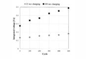
- FIG. 4 is a voltage / current waveform diagram of a new battery and each deteriorated battery, where (a) shows a sampling frequency of 1 [Hz] and (b) shows a sampling frequency of 2 [kHz]. It is a cycle characteristic figure of the voltage integral value (area S) of a new battery and each deterioration battery when sampling frequency is 1 [Hz] and 2 [kHz].
- FIG. 6 is a voltage / current waveform diagram of a new battery and each deteriorated battery when the charging time is 15 seconds and the sampling frequency is 1 [Hz].
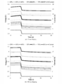
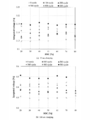
- FIG. 4 is a voltage / current waveform diagram of a new battery with different SOC at the end of charging, where (a) shows a case where the charging time is 15 seconds and (b) a case where the charging time is 100 seconds. It is a SOC characteristic figure of a voltage integral value (area S) in a new battery and each deterioration battery, and (a) is a figure when charging time is made into 15 seconds, and (b) when charging time is made into 100 seconds.
- FIG. 4 is a voltage / current waveform diagram of a new battery with different SOC at the end of charging, where (a) shows a case where the charging time is 15 seconds and (b) a case where the charging time is 100 seconds.
- SOC characteristic figure of a voltage integral value (area S) in a new battery and each deterioration battery and (a) is a figure when charging time is made into 15 seconds, and (b) when charging time is made into 100 seconds.
- FIG. 4 is a voltage / current waveform diagram of a new battery having different ambient temperatures, where (a) shows a case where the charging time is 15 seconds and (b) a case where the charging time is 100 seconds. It is a temperature characteristic figure of the voltage integral value (area S) in a new battery and each deterioration battery, and (a) is a figure when charging time is made into 15 seconds, and (b) when charging time is made into 100 seconds. It is the figure which added the approximated curve by the least square method to FIG.17 (b).
- FIG. 19 is a cycle characteristic diagram of coefficient A obtained from FIG. 18. It is a temperature characteristic figure of the average value (average value of area S) of the voltage integral value in a new battery and each deterioration battery. It is the figure which added the approximated curve by the least square method to FIG.
- FIG. 22 is a cycle characteristic diagram of coefficient A obtained from FIG. 21.
- the battery deterioration diagnosis method includes (1) a “charging step” for charging a lithium ion secondary battery, and (2) a battery terminal of the lithium ion secondary battery after completion of charging.
- the “calculation step” for integrating the potential difference obtained by subtracting the battery internal voltage from the battery terminal voltage and calculating the integral value of the potential difference; and (3) based on the calculated integral value.
- diagnosis step for diagnosing battery deterioration of the lithium ion secondary battery.
- the battery deterioration diagnosis method pays attention to this characteristic and diagnoses the battery deterioration of the lithium ion secondary battery based on the integrated value.
- the battery deterioration diagnosis apparatus is an apparatus for performing the battery deterioration diagnosis method according to the present embodiment, and can be configured by, for example, a microcomputer.
- the battery deterioration diagnosis device 1 calculates an integral value based on a signal relating to the voltage between the battery terminals of the lithium ion secondary battery acquired from the voltage detection means 3.
- a storage unit 12 that stores data relating to the battery deterioration characteristics of the integrated value, and a diagnosis unit 13 that diagnoses battery deterioration based on the integrated value calculated by the calculation unit 11 and the data stored in the storage unit 12. Including.
- the “charging step” of the battery deterioration diagnosis method is performed by the charging circuit 2 provided separately from the battery deterioration diagnosis device 1, but the “calculation step” is performed by the calculation unit 11 of the battery deterioration diagnosis device 1.
- the “diagnosis step” is performed by the diagnosis unit 13.
- Lithium ion secondary battery In the present embodiment, a cylindrical lithium ion secondary battery CGR18650CH manufactured by Panasonic is used as the lithium ion secondary battery. Table 1 shows the specifications of this battery.
- SOC is generally used as an index for expressing the state of charge of a lithium ion secondary battery.
- the SOC is a percentage of the stored charge quantity q (t) with respect to the battery nominal capacity (charge capacity) QBr .
- the definition formula of q (t) is shown in Formula (1), and the definition formula of SOC is shown in Formula (2).
- I B is the battery charging current
- q (t) is the charge amount after discharge start t seconds
- q (0) is the initial charging charge amount at the start of charging and discharging.
- constant current charging is performed at 1 [C] (2.25 [A]), and the voltage between the battery terminals of the lithium ion secondary battery reaches the upper limit voltage 4.2 [V]. 2 was treated with constant voltage charge at [V], a state in which the charging current I B when the constant voltage charging is narrowed to 0.05 [C] to SOC 100%. Further, constant current discharge is performed at 1 [C] (2.25 [A]), and a state where the voltage between the battery terminals of the lithium ion secondary battery reaches the lower limit voltage 2.75 [V] is defined as SOC 0%.
- the constant current charge and constant voltage charge described above were performed at an ambient temperature of 25 [° C.] to obtain SOC 100%, and then the constant current discharge described above was performed. From the equation (2), the SOC is set based on the battery discharge capacity.
- a new lithium ion secondary battery (hereinafter referred to as a new battery) and a lithium ion secondary battery (hereinafter referred to as a deteriorated battery) that has been charged and discharged up to 500 cycles every 100 cycles of charge / discharge from the new article (0 cycle). And examine the electrical characteristics.
- the current integration value when constant current discharge is performed at 1 [C] (2.25 [A]) from SOC 100% to SOC 0% is defined as battery discharge capacity
- the correlation of battery deterioration is shown in FIG. FIG. 2 shows that the battery discharge capacity decreases linearly with battery deterioration. That is, the battery nominal capacity QBr of the lithium ion secondary battery changes as the battery deteriorates.
- FIG. 3A and 3B show an equivalent circuit of a lithium ion secondary battery.
- the equivalent circuit shown in FIG. 3A is the simplest equivalent circuit in which the internal voltage V 0 and the internal resistance R B0 are connected in series.
- the actual lithium ion secondary battery hereinafter, actual batteries
- the potential drop V Z by the battery internal impedance even when subjected to constant current charge and discharge does not become constant.
- the actual battery has a transient characteristic in which the voltage between the battery terminals rises suddenly at the start of charging and then gradually rises with time, while it suddenly falls at the start of discharge and then gradually falls with time.
- Battery deterioration diagnosis method After the completion of charging, in the course of the voltage V B across the battery terminals converge to the battery internal voltage V 0 which is determined by the charging rate (SOC), battery internal voltage from the voltage V B across the battery terminals integrating the area of the potential difference obtained by subtracting the V 0 (integrated value) with S, diagnosing cell deterioration of the lithium ion secondary battery. Since this battery deterioration diagnosis method can diagnose battery deterioration using only simple four arithmetic operations mainly including numerical integration, it is relatively inexpensive and highly practical.
- FIG. 4 shows current / voltage waveforms when a lithium ion secondary battery is charged with a pulse current (rectangular wave current) having a time width of 100 seconds and an amplitude of 1 [C] (2.25 [A]).
- the transient response voltage waveform (battery voltage waveform between battery terminals) V B shown in FIG. 4 is equivalent to the CR parallel circuit in one stage in FIG. 3B, that is, the series resistor R B0 and one CR parallel.
- the battery internal voltage V 0 rises during charging and becomes constant after the end of charging.
- the battery terminal voltage waveform V B after the end of charging in which the charging rate (SOC) does not change and the fluctuation of the battery internal voltage V 0 does not need to be considered, is used for battery deterioration diagnosis.
- the battery internal voltage V 0 is originally a function of the SOC, but can be regarded as a constant determined by the SOC after the end of charging in the transient response voltage waveform after the end of charging where the SOC does not change. That is, if the SOC after charging is large, the battery internal voltage V 0 is large, and if the SOC after charging is small, the battery internal voltage V 0 is small.
- the area S obtained by subtracting and integrating the battery internal voltage V 0 from the battery terminal voltage V B corresponds to the hatched portion shown in FIG.
- the series resistance R B0 is greatly influenced by contact resistance and is not useful as a parameter used for battery deterioration diagnosis.
- the series resistance R B0 since the steep potential drop due to the series resistance R B0 immediately after the end of charging is not used, the series resistance R B0 can be separated from the equivalent circuit.
- the area S integrated by subtracting the battery internal voltage V 0 from the battery terminal voltage V B is expressed by the following equation (5). Given. If the time Tmax is infinite in the equation (5), the area S is given by the equation (6). From the equation (6), the area S is represented by the product of the charge amount q released after the charge is completed and the resistance R B1 . The amount of charge q is represented by the product of the resistor R B1 , the capacitor C B1 and the charging current I. Therefore, the comparison of the area S accompanying the battery deterioration is synonymous with comparing the change in the charge amount q accompanying the battery deterioration and the resistance R B1 .
- Each circuit constant in the equivalent circuit is such that the series resistance R B0 is 30 [m ⁇ ], the capacitor C B1 of the CR parallel circuit is 1 [F], and the resistance R B1 of the CR parallel circuit is 8 [m ⁇ ] to 16 [m ⁇ ]. Until 2 [m ⁇ ]. Further, the charging current was set to a pulse current of 1 [C] (2.25 [A]), and the charging time was set to 10 seconds so that the voltage V B between the battery terminals during charging was in a steady state. Under such conditions, the transient response voltage waveform (battery terminal voltage waveform) V B after the end of charging is observed, and the battery terminal voltage V B converges to the battery internal voltage V 0 after the end of charging. The area S integrated by subtracting the battery internal voltage V 0 from the battery terminal voltage V B is compared. The sampling frequency is set to 2 [kHz], and the area S is obtained by equation (7).
- ⁇ t is a time step.
- FIG. 6 shows a theoretical waveform of the voltage V B between the battery terminals after the end of charging when the resistance R B1 is 8 [m ⁇ ].
- the resistance R B1 characteristics of (5) theoretical value of the area S calculated by formula (Theoretical value) of the resistance R B1 characteristics, and the theoretical waveform (7) area was calculated by formula S (Without noise) Indicates. From Figure 7, with the resistance R B1 is large, it can be seen that the area S becomes larger in proportion to the resistance R B1. It can also be seen that the theoretical value of the area S calculated by the equation (5) and the area S calculated by the equation (7) from the theoretical waveform are in good agreement.
- the conditions at the time of verification by noise are the same as the conditions at the time of verification by the theoretical waveform described above.
- the superimposed noise is expressed by a random number of ⁇ 1 [mV] from the measured waveform result obtained by charging with a pulse current of 1 [C] (2.25 [A]).
- the amplitude of noise corresponds to 13.2% of the voltage (R B1 I) after the end of charging.
- FIG. 8 shows a theoretical waveform of the voltage V B between the battery terminals in consideration of the influence of noise after the end of charging when the resistance R B1 is 8 [m ⁇ ].
- FIG. 9 shows the resistance R B1 characteristics of the area S with and without considering the influence of noise.
- FIG. 9 shows that the area S increases almost linearly as the resistance R B1 increases even when the influence of noise is taken into account. Therefore, it can be said that the battery deterioration diagnosis method according to the present embodiment is useful as a technique for diagnosing battery deterioration because it is resistant to noise and has high stability.
- T max is not necessarily a time when the voltage V B across the battery terminals converged on the battery internal voltage V 0, the middle of the voltage V B across the battery terminals converge to the battery internal voltage V 0 at time There may be.
- the voltage V B across the battery terminals in the process of converging the battery internal voltage V Tmax, the integral of the voltage difference obtained by subtracting the battery internal voltage V Tmax from the voltage V B across the battery terminals Battery degradation can be diagnosed by the integrated value (area S).
- the test conditions for battery deterioration dependency are as follows: ambient temperature is 25 [° C.], SOC at the end of charging in a new battery and each deteriorated battery is 50%, charging current is 1 [C] (2.25 [A]) Pulse current.
- ambient temperature is 25 [° C.]
- SOC at the end of charging in a new battery is 50%
- charging current is 1 [C] (2.25 [A])
- Pulse current Pulse current.
- a characteristic test is performed with sampling frequencies of 1 [Hz] and 2 [kHz]. The charging time at this time is 100 seconds.
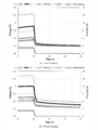
- FIG. 10 (a) When the sampling frequency is 1 [Hz] in FIG. 10 (a) and between the battery terminals before and after the end of charging in the new battery and each deteriorated battery in FIG. 10 (b) when the sampling frequency is 2 [kHz]. It shows the voltage V B.
- FIG. 11 shows the battery deterioration characteristics of the area S when the sampling frequency is 1 [Hz] and 2 [kHz]. From FIG. 11, even if the sampling frequency is lowered from 2 [kHz] to 1 [Hz], the area S is 9.15% at the maximum in the 500 cycle deteriorated battery, so the sampling frequency is set to 1 [Hz]. However, it can be seen that the battery deterioration diagnosis is possible.
- FIG. 12 shows the voltage V B between the battery terminals of the new battery and each deteriorated battery before and after the end of charging when the charging time is 15 seconds and the sampling frequency is 1 [Hz].
- FIG. 13 shows the battery deterioration dependency of the area S of the new battery and each deteriorated battery when the charging time is 15 seconds and 100 seconds and the sampling frequency is 1 [Hz].
- FIG. 13 shows that the area S increases in proportion to the battery deterioration. Further, when comparing the area S of the new battery and the 500 cycle battery, the area is 37.1% larger when charged for 15 seconds, and the area is larger than 77.4% when charged for 100 seconds.
- the battery deterioration diagnosis is possible even when the charging time is set to 15 seconds. However, since the change in the area S due to the battery deterioration becomes significant by increasing the charging time, the charging time is reduced. It can be seen that the accuracy of the battery deterioration diagnosis increases when the time is 100 seconds.
- SOC dependency The characteristic test conditions regarding the SOC dependency are: ambient temperature is 25 [° C.], SOC is 20% to 80% at the end of charging in a new battery and each deteriorated battery, charging current is amplitude 1 [C] (2.25 [A] ]) And the sampling frequency is 1 [Hz].
- FIG. 14 shows the voltage V B between the battery terminals of the new battery before and after the end of charging when the charging time is 15 seconds and 100 seconds and the SOC at the end of charging is changed from 20% to 80% in increments of 10%.
- FIG. 15 shows the SOC characteristics of the area S when charging a new battery and each deteriorated battery for 15 seconds and 100 seconds. As shown in FIG. 15 (a), in the case of a new battery having a charging time of 15 seconds, the largest difference of the area S due to the SOC is that the area S at the SOC 60% is 23.0% with respect to the area S at the SOC 20%. Observed at a large point. Further, the difference in the area S calculated between the new battery and the 500 cycle deteriorated battery is the smallest in that the area S of the 500 cycle deteriorated battery becomes 18.7% larger at 60% SOC.
- the largest difference of the area S due to the SOC is that the area S at the SOC 80% is 14.7 with respect to the area at the SOC 40%. Observed at the point of%. Further, the difference in the area S calculated between the new battery and the 500-cycle deteriorated battery is minimized because the area of the 500-cycle deteriorated battery becomes 65.4% larger at 50% SOC.
- Temperature dependence The test conditions related to temperature dependence are as follows: ambient temperature is changed from -10 [° C] to +40 [° C] every 10 [° C], SOC at the end of charging in new batteries and each deteriorated battery is 50%, charging current Is a pulse current having an amplitude of 1 [C] (2.25 [A]).
- the sampling frequency is 1 [Hz] and the charging time is 15 seconds and 100 seconds.
- FIG. 16 shows the voltage V B between the battery terminals before and after the end of charging when a new battery having a different ambient temperature is charged for 15 seconds and 100 seconds.
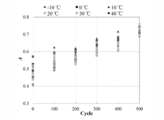
- FIG. 17 shows the temperature characteristics of the area S when the new battery and each deteriorated battery are charged for 15 seconds and 100 seconds. From FIG. 17, it can be seen that the area S decreases exponentially with increasing temperature in both cases where the charging time is 15 seconds and 100 seconds. Therefore, when the temperature at the time of charging is not constant, it is difficult to determine the battery deterioration by the battery deterioration diagnosis method according to the present embodiment. Therefore, it is preferable to perform temperature correction. In addition, it can be seen from FIG. 17 that the longer the charging time, the larger the change in the area S accompanying the battery deterioration. For this reason, it is preferable to provide the charging time for 100 seconds or more in which battery deterioration characteristics are sufficiently observed.
- FIG. 18 shows the temperature characteristic data of the area S shown in FIG. Table 2 shows the battery deterioration characteristics of each coefficient A and 1 / T t of the approximate curve shown in the equation (8).
- the coefficient A increases with battery deterioration.
- the coefficient 1 / T t does not depend on battery deterioration, and has a difference of 0.0041 [1 / ° C.] between 100 cycles and 500 cycles where the difference is maximum.
- Exp ( ⁇ T / T t ) in the equation (8) is considered to be constant without depending on battery deterioration.
- the coefficient 1 / T t is set to 0.0198 which is an average value of the new batteries and the respective deteriorated batteries shown in Table 2, and the equation (9) obtained by substituting the equation (8) into the area S in consideration of the temperature.
- the correction formula is as follows. That is, A is the area after temperature correction. FIG.
- the area S changes slightly depending on the SOC.
- the test conditions for deriving a high-accuracy temperature correction equation are: change the ambient temperature from -10 [° C] to +40 [° C] every 10 [° C], and change the SOC at the end of charging in new batteries and each deteriorated battery to 20%.
- the charging current is changed in 10% increments up to 80%, the charging current is a pulse current with an amplitude of 1 [C] (2.25 [A]), a charging time of 100 seconds, and the sampling frequency is 1 [Hz].
- FIG. 20 shows an average value of the area S calculated in each SOC.
- FIG. 21 shows the temperature characteristic data of the area S shown in FIG. 20 with an approximation curve obtained by the least square method.
- Table 3 shows the battery deterioration characteristics of each coefficient A and 1 / T t of the approximate curve shown in the equation (8).
- the coefficient (area after temperature correction) A increases as the battery deteriorates.
- the coefficient 1 / T t is not observed to be dependent on battery deterioration, and has a difference of 0.0045 [1 / ° C.] between the new battery having the maximum difference and the 400-cycle deterioration battery.
- the coefficient 1 / T t is set to 0.0176 which is an average value of the respective deteriorated batteries shown in Table 3, and the expression (10) obtained by substituting into the expression (8) is a highly accurate temperature correction expression.
- FIG. 22 shows the battery deterioration characteristic of coefficient A calculated by the temperature correction formula shown in formula (10).
- the shading of the color of the plot represents a change in SOC.
- FIG. 22 shows that the coefficient A increases with battery deterioration. Therefore, the battery deterioration diagnosis of the lithium ion secondary battery can be performed by obtaining the coefficient A in the equation (10).
- a battery deterioration diagnosis apparatus 1 illustrated in FIG. 1 is an apparatus for performing the battery deterioration diagnosis method according to the present embodiment, and includes a calculation unit 11, a storage unit 12, and a diagnosis unit 13.
- the charging circuit 2 for charging the lithium ion secondary battery and the battery deterioration diagnosis device 1 are provided separately, but the battery deterioration diagnosis device 1 is used as the charging circuit 2 or a protection device for the charging circuit 2 ( (Not shown).
- the battery deterioration diagnosis device 1 includes a signal related to the voltage V B between the battery terminals of the lithium ion secondary battery measured by the voltage measuring means 3, and the ambient temperature of the lithium ion secondary battery measured by the ambient temperature measuring means 4 ( A signal related to (outside air temperature) is input.
- the voltage measuring means 3 and the ambient temperature measuring means 4 are not included in the battery deterioration diagnosis apparatus 1, but these measurement means 3 and 4 may be included in the battery deterioration diagnosis apparatus 1.
- the calculation unit 11 After the end of charging of the lithium ion secondary battery (after the end of the charging step), the calculation unit 11 converges the voltage V B between the battery terminals of the lithium ion secondary battery to the battery internal voltage V 0 (battery internal voltage V Tmax ). In the process, the potential difference obtained by subtracting the battery internal voltage V 0 (battery internal voltage V Tmax ) from the battery terminal voltage V B is integrated, and an integrated value (area S) of the potential difference is calculated. For example, the calculation unit 11 can calculate the integral value (area S) according to the equation (7).
- ⁇ t is the sampling interval of the voltage measuring means 3
- n is the sampling number of the voltage measuring means 3
- m is the battery terminal voltage V B to the battery internal voltage V 0 (battery internal voltage V Tmax ). This is the total number of samplings until convergence.
- the storage unit 12 includes first data (for example, the profile shown in FIG. 11) indicating the relationship between the integral value (area S) and the number of charge / discharge cycles of the lithium ion secondary battery, and the ambient temperature of the lithium ion secondary battery.
- a correction function that increases exponentially with the rise of, for example, exp (T / T t ) in Expressions (9) and (10), and an integrated value (area A after temperature correction) corrected by the correction function
- Second data (for example, the profile shown in FIG. 22) indicating the relationship with the number of charge / discharge cycles of the lithium ion secondary battery is stored.
- the calculation unit 11 corrects the integral value (area S) based on the measurement result of the ambient temperature by the ambient temperature measurement unit 4 and the correction function, and the diagnosis unit 13 diagnoses the battery deterioration of the lithium ion secondary battery based on the integrated value after correction (area A after temperature correction) and the second data.
- the diagnosis unit 13 determines the lithium ion secondary battery based on the integral value (area S) calculated by the calculation unit 11 and the first data. Diagnose battery deterioration.
- the battery deterioration diagnosis device 1 is highly practical as a consumer product, and is expected to contribute to safe operation by being mounted on a protection device such as a battery management system (BMS).
- BMS battery management system
- the area (integrated value) S ′ obtained by integrating the battery terminal voltage V B is used.
- the battery internal voltage V 0 is substantially proportional to the SOC after the end of charging, and therefore the area S ′ is greatly affected by the SOC. For this reason, when performing battery deterioration diagnosis using the area S ′, battery deterioration cannot be diagnosed unless the SOC of the lithium ion secondary battery is estimated.
- a lithium ion secondary battery has been described as an example of a secondary battery, but the battery deterioration diagnosis method and the battery deterioration diagnosis apparatus according to the present invention are secondary batteries other than lithium ion secondary batteries. It can also be applied to.
- the pulse current is used in the charging step, but any current can be used as long as the current value instantaneously becomes zero at the end of charging.
Landscapes
- Engineering & Computer Science (AREA)
- Chemical & Material Sciences (AREA)
- Chemical Kinetics & Catalysis (AREA)
- General Chemical & Material Sciences (AREA)
- Electrochemistry (AREA)
- Manufacturing & Machinery (AREA)
- General Physics & Mathematics (AREA)
- Physics & Mathematics (AREA)
- Power Engineering (AREA)
- Materials Engineering (AREA)
- Secondary Cells (AREA)
- Charge And Discharge Circuits For Batteries Or The Like (AREA)
- Tests Of Electric Status Of Batteries (AREA)
Abstract
Description
過渡特性を有する二次電池の電池劣化を診断する電池劣化診断方法であって、
前記二次電池に対して充電を行う充電ステップと、
前記充電の終了後、前記二次電池の電池端子間電圧が前記二次電池の電池内部電圧に収束する過程において、前記電池端子間電圧から前記電池内部電圧を差し引いた電位差を積分し、前記電位差の積分値を算出する演算ステップと、
前記積分値に基づいて前記二次電池の電池劣化を診断する診断ステップと、を含む
ことを特徴とする。
前記演算ステップでは、前記二次電池の周囲温度の上昇に伴い指数関数的に大きくなる補正関数により、前記積分値の補正を行い、
前記診断ステップでは、補正後の前記積分値に基づいて前記二次電池の電池劣化を診断することが好ましい。
過渡特性を有する二次電池の電池劣化を診断する電池劣化診断装置であって、
前記二次電池の充電の終了後、前記二次電池の電池端子間電圧が前記二次電池の電池内部電圧に収束する過程において、前記電池端子間電圧から前記電池内部電圧を差し引いた電位差を積分し、前記電位差の積分値を算出する演算部と、
前記積分値の電池劣化特性に関する第1データが格納された記憶部と、
前記演算部で算出された前記積分値と、前記記憶部に格納された前記第1データとに基づいて、前記二次電池の電池劣化を診断する診断部と、を含む
ことを特徴とする。
前記記憶部には、前記二次電池の周囲温度の上昇に伴い指数関数的に大きくなる補正関数と、前記補正関数により補正された前記積分値の電池劣化特性に関する第2データとが格納されており、
前記演算部は、前記補正関数により前記積分値の補正を行い、
前記診断部は、補正後の前記積分値と前記第2データとに基づいて前記二次電池の電池劣化を診断することが好ましい。
本発明の一実施形態に係る電池劣化診断方法は、(1)リチウムイオン二次電池に対して充電を行う「充電ステップ」と、(2)充電の終了後、リチウムイオン二次電池の電池端子間電圧が電池内部電圧に収束する過程において、電池端子間電圧から電池内部電圧を差し引いた電位差を積分し、電位差の積分値を算出する「演算ステップ」と、(3)算出した積分値に基づいてリチウムイオン二次電池の電池劣化を診断する「診断ステップ」とを含む。
本実施形態では、リチウムイオン二次電池として、Panasonic社製円筒型リチウムイオン二次電池CGR18650CHを使用した。この電池の仕様を表1に示す。




以下、本実施形態に係る電池劣化診断方法について、詳しく説明する。本実施形態に係る電池劣化診断方法は、充電終了後、電池端子間電圧VBが充電率(SOC)で定まる電池内部電圧V0に収束する過程において、電池端子間電圧VBから電池内部電圧V0を差し引いた電位差を積分した面積(積分値)Sを用いて、リチウムイオン二次電池の電池劣化を診断する。この電池劣化診断方法は、数値積分を主とする簡単な四則演算のみを用いて電池劣化を診断することができるため、比較的安価で実用性が高い。


まず、理論波形による検証について説明する。電池端子間電圧VBの理論波形を計算するにあたり、直列抵抗RB0とCR並列回路を直列に接続したCR並列1段の等価回路を用いる。充電終了後の電池端子間電圧VBが電池内部電圧V0に収束する過程において、電池内部電圧V0は、一定であるため考慮しない。このため、電池端子間電圧VBの理論波形は、電池端子間電圧VBから電池内部電圧V0を除いた波形により表現できる。等価回路における各回路定数は、直列抵抗RB0を30[mΩ]とし、CR並列回路のキャパシタCB1を1[F]とし、CR並列回路の抵抗RB1を8[mΩ]から16[mΩ]まで2[mΩ]毎に変化させることとした。また、充電電流を1[C](2.25[A])のパルス電流とし、充電中における電池端子間電圧VBが定常状態となるよう、充電時間を10秒間とした。このような条件の下、充電終了後の過渡応答電圧波形(電池端子間電圧波形)VBの観測を行い、充電終了後に電池端子間電圧VBが電池内部電圧V0に収束する過程において、電池端子間電圧VBから電池内部電圧V0を差し引いて積分した面積Sの比較を行う。サンプリング周波数を2[kHz]とし、面積Sを(7)式により求める。ここで、△tを時間刻みとする。

実電池はSOCや温度等の運用状況により特性が変化することから、各特性試験を行うことにより、本実施形態に係る電池劣化診断方法の有用性を検討する。併せて、本実施形態に係る電池劣化診断方法に必要な電流パルス幅、サンプリング周波数、最大観測時間等を検討する。各特性試験において数値積分は、充電終了後Tmax秒間(例えば、30秒間)実施するものとし、充電終了後Tmax秒経過時の電池端子間電圧VBを電池内部電圧VTmaxと定義し、(7)式を用いて計算する。すなわち、Tmaxは、必ずしも電池端子間電圧VBが電池内部電圧V0に収束したときの時間である必要はなく、電池端子間電圧VBが電池内部電圧V0に収束する途中の時間であってもよい。したがって、本実施形態に係る電池劣化診断方法は、電池端子間電圧VBが電池内部電圧VTmaxに収束する過程において、電池端子間電圧VBから電池内部電圧VTmaxを差し引いた電位差を積分した積分値(面積S)により、電池劣化を診断することができる。
電池劣化依存性に関する試験条件は、周囲温度を25[℃]、新品電池および各劣化電池における充電終了時のSOCを50%、充電電流を振幅1[C](2.25[A])のパルス電流とする。まず、電池劣化診断が可能な時間刻みを検討するため、サンプリング周波数を1[Hz]および2[kHz]とし、特性試験を行う。このときの充電時間は100秒間とする。
SOC依存性に関する特性試験条件は、周囲温度を25[℃]、新品電池および各劣化電池における充電終了時のSOCを20%~80%、充電電流を振幅1[C](2.25[A])のパルス電流、サンプリング周波数を1[Hz]とする。
温度依存性に関する試験条件は、周囲温度を-10[℃]~+40[℃]まで10[℃]毎に変化させ、新品電池および各劣化電池における充電終了時のSOCを50%とし、充電電流を振幅1[C](2.25[A])のパルス電流とする。また、サンプリング周波数を1[Hz]とし、充電時間を15秒間および100秒間とする。
次に、充電時間を100秒間として温度補正の検討を行う。図17に示すように、温度の上昇に伴い面積Sが指数関数的に小となるため、図17(b)に示す実測データから、最小二乗法により近似曲線を求める。面積Sは、周囲温度Tを用いて(8)式に示す指数関数で表現することができる。



図1に示す電池劣化診断装置1は、本実施形態に係る電池劣化診断方法を行うための装置であり、演算部11と、記憶部12と、診断部13とを含む。なお、図1では、リチウムイオン二次電池の充電を行う充電回路2と電池劣化診断装置1とを別々に設けているが、電池劣化診断装置1を充電回路2もしくは充電回路2の保護装置(図示略)に内蔵してもよい。電池劣化診断装置1には、電圧測定手段3により測定されたリチウムイオン二次電池の電池端子間電圧VBに関する信号と、周囲温度測定手段4により測定されたリチウムイオン二次電池の周囲温度(外気温度)に関する信号が入力される。なお、図1では、電圧測定手段3および周囲温度測定手段4を電池劣化診断装置1に含めていないが、これらの測定手段3、4を電池劣化診断装置1に含めてもよい。
2 充電回路
3 電圧検出手段
4 周囲温度測定手段
11 演算部
12 記憶部
13 診断部
Claims (4)
- 過渡特性を有する二次電池の電池劣化を診断する電池劣化診断方法であって、
前記二次電池に対して充電を行う充電ステップと、
前記充電の終了後、前記二次電池の電池端子間電圧が前記二次電池の電池内部電圧に収束する過程において、前記電池端子間電圧から前記電池内部電圧を差し引いた電位差を積分し、前記電位差の積分値を算出する演算ステップと、
前記積分値に基づいて前記二次電池の電池劣化を診断する診断ステップと、を含む
ことを特徴とする電池劣化診断方法。 - 前記演算ステップでは、前記二次電池の周囲温度の上昇に伴い指数関数的に大きくなる補正関数により、前記積分値の補正を行い、
前記診断ステップでは、補正後の前記積分値に基づいて前記二次電池の電池劣化を診断する
ことを特徴とする請求項1に記載の電池劣化診断方法。 - 過渡特性を有する二次電池の電池劣化を診断する電池劣化診断装置であって、
前記二次電池の充電の終了後、前記二次電池の電池端子間電圧が前記二次電池の電池内部電圧に収束する過程において、前記電池端子間電圧から前記電池内部電圧を差し引いた電位差を積分し、前記電位差の積分値を算出する演算部と、
前記積分値の電池劣化特性に関する第1データが格納された記憶部と、
前記演算部で算出された前記積分値と、前記記憶部に格納された前記第1データとに基づいて、前記二次電池の電池劣化を診断する診断部と、を含む
ことを特徴とする電池劣化診断装置。 - 前記記憶部には、前記二次電池の周囲温度の上昇に伴い指数関数的に大きくなる補正関数と、前記補正関数により補正された前記積分値の電池劣化特性に関する第2データとが格納されており、
前記演算部は、前記補正関数により前記積分値の補正を行い、
前記診断部は、補正後の前記積分値と前記第2データとに基づいて前記二次電池の電池劣化を診断する
ことを特徴とする請求項3に記載の電池劣化診断装置。
Priority Applications (3)
| Application Number | Priority Date | Filing Date | Title |
|---|---|---|---|
| US15/552,842 US10379170B2 (en) | 2015-02-24 | 2016-02-24 | Cell deterioration diagnostic based on integrated value |
| JP2017502416A JP6579552B2 (ja) | 2015-02-24 | 2016-02-24 | 電池劣化診断方法および電池劣化診断装置 |
| EP16755532.5A EP3264120B1 (en) | 2015-02-24 | 2016-02-24 | Cell deterioration diagnostic method and cell deterioration diagnostic device |
Applications Claiming Priority (2)
| Application Number | Priority Date | Filing Date | Title |
|---|---|---|---|
| JP2015033944 | 2015-02-24 | ||
| JP2015-033944 | 2015-02-24 |
Publications (1)
| Publication Number | Publication Date |
|---|---|
| WO2016136788A1 true WO2016136788A1 (ja) | 2016-09-01 |
Family
ID=56788472
Family Applications (1)
| Application Number | Title | Priority Date | Filing Date |
|---|---|---|---|
| PCT/JP2016/055374 Ceased WO2016136788A1 (ja) | 2015-02-24 | 2016-02-24 | 電池劣化診断方法および電池劣化診断装置 |
Country Status (4)
| Country | Link |
|---|---|
| US (1) | US10379170B2 (ja) |
| EP (1) | EP3264120B1 (ja) |
| JP (1) | JP6579552B2 (ja) |
| WO (1) | WO2016136788A1 (ja) |
Cited By (9)
| Publication number | Priority date | Publication date | Assignee | Title |
|---|---|---|---|---|
| CN110208710A (zh) * | 2019-06-30 | 2019-09-06 | 潍柴动力股份有限公司 | 一种燃料电池发动机瞬态响应性能的检测方法和系统 |
| JP2019160775A (ja) * | 2018-03-09 | 2019-09-19 | プライムアースEvエナジー株式会社 | 電極板検査装置及び電極板検査方法 |
| WO2020090143A1 (ja) * | 2018-10-30 | 2020-05-07 | エンネット株式会社 | 電流パルス法による電池診断装置及び電池診断方法 |
| WO2020128743A1 (ja) * | 2018-12-20 | 2020-06-25 | 株式会社半導体エネルギー研究所 | 半導体装置および電池パック |
| WO2020255794A1 (ja) * | 2019-06-20 | 2020-12-24 | 株式会社Gsユアサ | 開発支援装置、開発支援方法、および状態検知方法 |
| JP2022122657A (ja) * | 2021-02-10 | 2022-08-23 | 株式会社豊田自動織機 | 燃料電池システム |
| JP2022127244A (ja) * | 2021-02-19 | 2022-08-31 | 日立グローバルライフソリューションズ株式会社 | 電池状態推定装置および方法 |
| JPWO2023238426A1 (ja) * | 2022-06-08 | 2023-12-14 | ||
| WO2025197446A1 (ja) * | 2024-03-22 | 2025-09-25 | パナソニックIpマネジメント株式会社 | 電池状態推定システム、電池状態推定方法、及び電池状態推定プログラム |
Families Citing this family (7)
| Publication number | Priority date | Publication date | Assignee | Title |
|---|---|---|---|---|
| CN111801586B (zh) * | 2018-03-07 | 2023-08-01 | 松下知识产权经营株式会社 | 可充电电池的残存性能评价方法、可充电电池的残存性能评价程序、运算装置及残存性能评价系统 |
| CN110988728B (zh) * | 2019-11-25 | 2023-08-04 | 安徽绿沃循环能源科技有限公司 | 一种锂电池包内部连接异常快速诊断方法 |
| DE102019133921A1 (de) * | 2019-12-11 | 2021-06-17 | Bayerische Motoren Werke Aktiengesellschaft | Verfahren, Vorrichtung, System, Elektrofahrzeug, Computerprogramm und Speichermedium zum Laden oder Entladen einer Zelle eines elektrischen Energiespeichers |
| KR102754173B1 (ko) * | 2021-03-26 | 2025-01-10 | 주식회사 엘지에너지솔루션 | 배터리 진단 장치 및 방법 |
| CN115061044B (zh) * | 2022-07-04 | 2025-01-14 | 北京电满满科技有限公司 | 基于bms通讯检测技术的锂电池健康评估方法及系统 |
| CN116736150B (zh) * | 2023-08-16 | 2023-11-03 | 杭州高特电子设备股份有限公司 | 一种电池异常检测方法、电池系统和计算机程序 |
| US20250091474A1 (en) * | 2023-09-19 | 2025-03-20 | Fca Us Llc | Static state of charge correction techniques for lithium iron phosphate battery systems |
Citations (3)
| Publication number | Priority date | Publication date | Assignee | Title |
|---|---|---|---|---|
| JP2007178333A (ja) * | 2005-12-28 | 2007-07-12 | Toyota Motor Corp | 二次電池の劣化状態の推定方法と車載二次電池の劣化状態推定装置。 |
| JP2011054413A (ja) * | 2009-09-01 | 2011-03-17 | Nissan Motor Co Ltd | 二次電池の劣化状態判別システム、および二次電池の劣化状態判別方法 |
| JP2013239328A (ja) * | 2012-05-15 | 2013-11-28 | Furukawa Electric Co Ltd:The | 蓄電池の運用管理方法及び運用管理装置 |
Family Cites Families (6)
| Publication number | Priority date | Publication date | Assignee | Title |
|---|---|---|---|---|
| JP2004301780A (ja) * | 2003-03-31 | 2004-10-28 | Yazaki Corp | バッテリ状態監視装置及びその方法、並びに、放電可能容量検出方法 |
| JP2007108063A (ja) | 2005-10-14 | 2007-04-26 | Furukawa Electric Co Ltd:The | 二次電池劣化判定方法、二次電池劣化判定装置、及び電源システム |
| JP2009250796A (ja) * | 2008-04-07 | 2009-10-29 | Mitsubishi Electric Corp | 蓄電池の劣化診断方法および診断システム |
| JP5044511B2 (ja) * | 2008-09-03 | 2012-10-10 | トヨタ自動車株式会社 | リチウムイオン電池の劣化判定方法、リチウムイオン電池の制御方法、リチウムイオン電池の劣化判定装置、リチウムイオン電池の制御装置及び車両 |
| WO2012157747A1 (ja) | 2011-05-18 | 2012-11-22 | 古河電気工業株式会社 | 組電池の制御方法及び制御装置 |
| US9291682B2 (en) * | 2012-03-30 | 2016-03-22 | Panasonic Intellectual Property Management Co., Ltd. | Degradation state estimating method and degradation state estimating apparatus |
-
2016
- 2016-02-24 US US15/552,842 patent/US10379170B2/en active Active
- 2016-02-24 EP EP16755532.5A patent/EP3264120B1/en active Active
- 2016-02-24 JP JP2017502416A patent/JP6579552B2/ja not_active Expired - Fee Related
- 2016-02-24 WO PCT/JP2016/055374 patent/WO2016136788A1/ja not_active Ceased
Patent Citations (3)
| Publication number | Priority date | Publication date | Assignee | Title |
|---|---|---|---|---|
| JP2007178333A (ja) * | 2005-12-28 | 2007-07-12 | Toyota Motor Corp | 二次電池の劣化状態の推定方法と車載二次電池の劣化状態推定装置。 |
| JP2011054413A (ja) * | 2009-09-01 | 2011-03-17 | Nissan Motor Co Ltd | 二次電池の劣化状態判別システム、および二次電池の劣化状態判別方法 |
| JP2013239328A (ja) * | 2012-05-15 | 2013-11-28 | Furukawa Electric Co Ltd:The | 蓄電池の運用管理方法及び運用管理装置 |
Non-Patent Citations (1)
| Title |
|---|
| See also references of EP3264120A4 * |
Cited By (22)
| Publication number | Priority date | Publication date | Assignee | Title |
|---|---|---|---|---|
| JP2019160775A (ja) * | 2018-03-09 | 2019-09-19 | プライムアースEvエナジー株式会社 | 電極板検査装置及び電極板検査方法 |
| JP7018374B2 (ja) | 2018-03-09 | 2022-02-10 | プライムアースEvエナジー株式会社 | 電極板検査装置及び電極板検査方法 |
| JPWO2020090143A1 (ja) * | 2018-10-30 | 2021-11-25 | エンネット株式会社 | 電流パルス法による電池診断装置及び電池診断方法 |
| WO2020090143A1 (ja) * | 2018-10-30 | 2020-05-07 | エンネット株式会社 | 電流パルス法による電池診断装置及び電池診断方法 |
| US11422194B2 (en) | 2018-10-30 | 2022-08-23 | Ennet Company Limited | Battery diagnosis apparatus and battery diagnosis method based on current pulse method |
| JP6991616B2 (ja) | 2018-10-30 | 2022-01-12 | エンネット株式会社 | 電流パルス法による電池診断装置及び電池診断方法 |
| WO2020128743A1 (ja) * | 2018-12-20 | 2020-06-25 | 株式会社半導体エネルギー研究所 | 半導体装置および電池パック |
| JPWO2020128743A1 (ja) * | 2018-12-20 | 2020-06-25 | ||
| US11988720B2 (en) | 2018-12-20 | 2024-05-21 | Semiconductor Energy Laboratory Co., Ltd. | Semiconductor device and battery pack |
| JP7526671B2 (ja) | 2018-12-20 | 2024-08-01 | 株式会社半導体エネルギー研究所 | 半導体装置および電池パック |
| WO2020255794A1 (ja) * | 2019-06-20 | 2020-12-24 | 株式会社Gsユアサ | 開発支援装置、開発支援方法、および状態検知方法 |
| US12596853B2 (en) | 2019-06-20 | 2026-04-07 | Gs Yuasa International Ltd. | Development support apparatus, development support method, and state detection method |
| CN110208710B (zh) * | 2019-06-30 | 2021-06-22 | 潍柴动力股份有限公司 | 一种燃料电池发动机瞬态响应性能的检测方法和系统 |
| CN110208710A (zh) * | 2019-06-30 | 2019-09-06 | 潍柴动力股份有限公司 | 一种燃料电池发动机瞬态响应性能的检测方法和系统 |
| JP2022122657A (ja) * | 2021-02-10 | 2022-08-23 | 株式会社豊田自動織機 | 燃料電池システム |
| JP7487125B2 (ja) | 2021-02-10 | 2024-05-20 | 株式会社豊田自動織機 | 燃料電池システム |
| JP7478684B2 (ja) | 2021-02-19 | 2024-05-07 | 日立グローバルライフソリューションズ株式会社 | 電池状態推定装置および方法 |
| JP2022127244A (ja) * | 2021-02-19 | 2022-08-31 | 日立グローバルライフソリューションズ株式会社 | 電池状態推定装置および方法 |
| WO2023238426A1 (ja) * | 2022-06-08 | 2023-12-14 | 株式会社デンソー | 電池インピーダンス推定装置及び電池インピーダンス推定方法 |
| JPWO2023238426A1 (ja) * | 2022-06-08 | 2023-12-14 | ||
| JP7616487B2 (ja) | 2022-06-08 | 2025-01-17 | 株式会社デンソー | 電池インピーダンス推定装置及び電池インピーダンス推定方法 |
| WO2025197446A1 (ja) * | 2024-03-22 | 2025-09-25 | パナソニックIpマネジメント株式会社 | 電池状態推定システム、電池状態推定方法、及び電池状態推定プログラム |
Also Published As
| Publication number | Publication date |
|---|---|
| US20180038918A1 (en) | 2018-02-08 |
| EP3264120B1 (en) | 2022-08-10 |
| JP6579552B2 (ja) | 2019-09-25 |
| US10379170B2 (en) | 2019-08-13 |
| EP3264120A1 (en) | 2018-01-03 |
| EP3264120A4 (en) | 2018-12-05 |
| JPWO2016136788A1 (ja) | 2017-11-30 |
Similar Documents
| Publication | Publication Date | Title |
|---|---|---|
| JP6579552B2 (ja) | 電池劣化診断方法および電池劣化診断装置 | |
| US10989761B2 (en) | Method for estimating the state of health of a battery | |
| TWI818777B (zh) | 電池管理裝置、電池管理方法 | |
| CN103250066B (zh) | 感测电池容量的系统和方法 | |
| US10288693B2 (en) | State of charge estimator and methods of making and using the same | |
| EP2597476A1 (en) | Battery state estimating apparatus and battery state estimating method | |
| JP5812968B2 (ja) | 電流センサ故障検知装置、電池システム、及び電流センサ故障検知方法 | |
| KR20120135075A (ko) | 상태 판정 장치, 축전 장치, 상태 판정 방법 | |
| JP6470022B2 (ja) | 電池残量予測装置及びバッテリパック | |
| KR102695066B1 (ko) | 배터리 상태 모니터링 장치 및 방법 | |
| EP3605123B1 (en) | Storage battery control device and control method | |
| CN101339230A (zh) | 电池内阻测量装置和方法 | |
| WO2023095500A1 (ja) | 二次電池の状態診断方法および状態診断装置 | |
| JP6895541B2 (ja) | 二次電池監視装置、二次電池状態演算装置および二次電池状態推定方法 | |
| Ke et al. | Battery modelling and SOC estimation of a LiFePO4 battery | |
| EP3015835B1 (en) | A method and a system for determining the operating temperature of a cell of an electric charge accumulator assembly without physical temperature sensors, particularly for electric or hybrid motor vehicles | |
| TWI801263B (zh) | 電容量估計方法、電池模組及其電器產品 | |
| CN112415409A (zh) | 估算电池容量的方法和装置、存储介质及车辆 | |
| KR102892944B1 (ko) | 방전 전압 그래프 예측 방법 및 이를 이용한 배터리 시스템 | |
| JP6541412B2 (ja) | 充電率算出方法及び充電率算出装置 | |
| CN112394290A (zh) | 电池包soh的估算方法、装置、计算机设备和存储介质 | |
| CN117396769A (zh) | 电池异常检测装置以及电池异常检测方法 | |
| Li et al. | A fast identification method for internal short circuit resistance in lithium-ion battery based on voltage drop | |
| CN117741477A (zh) | 检测电池内短路故障的方法及装置 | |
| US20250155513A1 (en) | Measurement system and method for calculating resistance of internal short circuit of battery and method for establishing battery reference sample |
Legal Events
| Date | Code | Title | Description |
|---|---|---|---|
| 121 | Ep: the epo has been informed by wipo that ep was designated in this application |
Ref document number: 16755532 Country of ref document: EP Kind code of ref document: A1 |
|
| ENP | Entry into the national phase |
Ref document number: 2017502416 Country of ref document: JP Kind code of ref document: A |
|
| WWE | Wipo information: entry into national phase |
Ref document number: 15552842 Country of ref document: US |
|
| NENP | Non-entry into the national phase |
Ref country code: DE |
|
| REEP | Request for entry into the european phase |
Ref document number: 2016755532 Country of ref document: EP |