WO2016136947A1 - 周波数変換器、計測システム及び計測方法 - Google Patents
周波数変換器、計測システム及び計測方法 Download PDFInfo
- Publication number
- WO2016136947A1 WO2016136947A1 PCT/JP2016/055825 JP2016055825W WO2016136947A1 WO 2016136947 A1 WO2016136947 A1 WO 2016136947A1 JP 2016055825 W JP2016055825 W JP 2016055825W WO 2016136947 A1 WO2016136947 A1 WO 2016136947A1
- Authority
- WO
- WIPO (PCT)
- Prior art keywords
- signal
- frequency
- frequency converter
- output
- input
- Prior art date
- Legal status (The legal status is an assumption and is not a legal conclusion. Google has not performed a legal analysis and makes no representation as to the accuracy of the status listed.)
- Ceased
Links
Images


Classifications
-
- G—PHYSICS
- G01—MEASURING; TESTING
- G01R—MEASURING ELECTRIC VARIABLES; MEASURING MAGNETIC VARIABLES
- G01R23/00—Arrangements for measuring frequencies; Arrangements for analysing frequency spectra
- G01R23/02—Arrangements for measuring frequency, e.g. pulse repetition rate; Arrangements for measuring period of current or voltage
- G01R23/14—Arrangements for measuring frequency, e.g. pulse repetition rate; Arrangements for measuring period of current or voltage by heterodyning; by beat-frequency comparison
-
- G—PHYSICS
- G01—MEASURING; TESTING
- G01R—MEASURING ELECTRIC VARIABLES; MEASURING MAGNETIC VARIABLES
- G01R27/00—Arrangements for measuring resistance, reactance, impedance, or electric characteristics derived therefrom
- G01R27/28—Measuring attenuation, gain, phase shift or derived characteristics of electric four pole networks, i.e. two-port networks; Measuring transient response
- G01R27/32—Measuring attenuation, gain, phase shift or derived characteristics of electric four pole networks, i.e. two-port networks; Measuring transient response in circuits having distributed constants, e.g. having very long conductors or involving high frequencies
-
- H—ELECTRICITY
- H03—ELECTRONIC CIRCUITRY
- H03D—DEMODULATION OR TRANSFERENCE OF MODULATION FROM ONE CARRIER TO ANOTHER
- H03D7/00—Transference of modulation from one carrier to another, e.g. frequency-changing
Definitions
- the present application relates to a frequency converter, a measurement system, and a measurement method.
- This application claims priority on February 27, 2015 based on Japanese Patent Application No. 2015-39192 filed in Japan, the contents of which are incorporated herein by reference.
- IEEE 802.11ad which is being studied as an international standard for increasing the speed of wireless LAN (local area network), has a carrier frequency of about 60 GHz and is expected to use millimeter-wave radio waves.
- a radio wave electromagnétique wave
- a radio wave with a frequency of 3 GHz to 30 GHz is called a centimeter wave
- both are included in a microwave indicating a radio wave with a frequency of 300 MHz to 3 THz.
- the modulation band is 2.16 GHz per channel, which is scheduled to be about 10 to 100 times the conventional band.
- device characteristics are evaluated by the following method. That is, device characteristics are evaluated by combining a measuring device corresponding to a conventional frequency band (for example, a centimeter wave band) and a frequency converter.
- the frequency converter is, for example, a device that down-converts a millimeter wave signal into a centimeter wave or up-converts a centimeter wave signal into a millimeter wave.
- the following issues arise when using a frequency converter. That is, the above-described frequency converter that inputs or outputs a modulation signal in which the band of one channel is 2.16 GHz is very expensive. In addition, the setup for performing the measurement is complicated, and there is a possibility that a connection error of the device is likely to occur, and adjustment takes time.
- a mixer that is, a mixer
- FIG. 7 shows an example of the configuration of a mixer provided in a frequency converter used for millimeter waves.
- a frequency converter with a flat frequency characteristic that can handle a millimeter-wave ultra-wideband modulation signal.
- it is difficult to directly generate a centimeter wave to a millimeter wave signal and directly convert a millimeter wave to a centimeter wave signal while maintaining a flat frequency characteristic. Therefore, it is general to employ a double super heterodyne frequency converter 200 as shown in FIG.
- the frequency converter 200 shown in FIG. 7 includes two mixers 201 and 202 that input two different types of frequencies f LO1 and f LO2 as local oscillation signals.
- the frequency converter 200 When used as an up-converter, the frequency converter 200 inputs a modulation signal having a frequency f IF1 to the mixer 201 and converts it into a signal having an intermediate frequency f IF2 that is the sum of the frequency f IF1 and the frequency f LO1. . Further, the signal of frequency f IF2 is input to mixer 202 and converted to a high frequency signal of frequency f RF that is the sum of frequency f IF2 and frequency f LO2 .
- the frequency converter 200 inputs a high-frequency signal having the frequency f RF to the mixer 202 and converts the high-frequency signal into a signal having an intermediate frequency f IF2 that is a difference value between the frequency f RF and the frequency f LO2. Is done. Further, a signal of a frequency f IF2 inputted to the mixer 201, is converted to a modulated signal of a frequency f IF1 of the value of the difference frequency f IF2 and the frequency f LO1.
- the double superheterodyne frequency converter 200 shown in FIG. 7 includes two mixers. For this reason, two types of local oscillation signals must be prepared. Also, wiring between the mixers is required. These configurations can contribute to high prices, complicated setup during measurement, increased possibility of incorrect connection of devices, and longer adjustment time.
- This application can provide a frequency converter, a measurement system, and a measurement method.
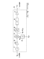
- FIG. 1 is a system diagram illustrating a configuration example of a measurement system 1 as an embodiment of the present application.
- 5 is a flowchart showing an example of a flow of measurement processing by the measurement system 1 of FIG. It is the figure which showed an example of the comparison result of the presence or absence of correction
- FIG. 1 is a diagram illustrating a configuration example of a harmonic mixer 100 included in a frequency converter as an embodiment of the present application.
- the embodiment of the present application relates to a harmonic mixer as a frequency converter having a flat frequency characteristic for measurement of an ultra-wideband modulated signal that is a millimeter wave, for example, a signal in a frequency band corresponding to the IEEE802.11ad standard. is there.
- the present embodiment relates to a measurement system that can easily measure an ultra-wideband modulation signal, which is a millimeter wave, using a general-purpose digital oscilloscope so as to correspond to the IEEE802.11ad standard using this harmonic mixer. Is.
- a harmonic mixer 100 shown in FIG. 1 is a mixer that internally includes a circuit that distorts an input local oscillation signal and generates its harmonics.
- Harmonic mixer 100 receives a local oscillation signal of a frequency f LO1, and generates the harmonics of n times the frequency n ⁇ f LO1 of by distorting the local oscillation signal within the mixer, the frequency n ⁇ f
- the harmonic of LO1 is mixed with an input signal of frequency f RF (in the case of a down converter) or an input signal of frequency f IF1 (in the case of an up converter).
- the harmonic mixer 100 when used as an up-converter, by appropriately selecting the local oscillation signal, the harmonic (n ⁇ f LO1 ) of a certain local oscillation signal and the input frequency (f IF1 ) are mixed and an appropriate output is obtained. An output signal having a frequency (f RF ) is obtained.
- the relationship is shown by the following equation.
- the frequency converter 10 shown in FIG. 2 is configured as an up-converter.
- the frequency converter 10 shown in FIG. 2 includes a harmonic mixer 11, a high pass filter 12, a power amplifier (PA) 13, an isolator 14, and a multiplier 15.
- PA power amplifier
- a high frequency signal of f LO1 ) is generated and output as an output signal.
- an active doubler active multiplier that doubles the frequency of the input signal and outputs it
- the power of the output local oscillation signal after multiplication varies depending on the frequency to be multiplied.
- the local oscillation output from the multiplier 15 is obtained. Since the signal level of the signal is unstable, the output signal output from the frequency converter 10 cannot be corrected with high accuracy, and a correct measurement result cannot be obtained. For this reason, in this embodiment, in order to make the signal level after multiplication constant so that a local oscillation signal with a constant power is output in a predetermined frequency band, an AGC (automatic gain control) amplifier function or A power saturation function is added, and a multiplied local oscillation signal is output to the harmonic mixer 11 with a constant power without changing the signal level at any frequency within a predetermined frequency band.
- AGC automatic gain control
- the power level when the local oscillation signal is supplied to the harmonic mixer 11 is stabilized in a wide frequency band, and each of the modulation accuracy and the signal level reproducibility in the harmonic mixer 11 is achieved.
- the frequency characteristics (S parameters) of the amplitude and phase of the frequency converter 10 are measured in advance, and when the correction processing of the signal output from the frequency converter 10 is performed based on the frequency characteristics, the output from the multiplier 15 is output. Since the signal level of the local oscillation signal is constant regardless of the frequency, the signal output from the frequency converter 10 can be corrected with high accuracy at any frequency in a predetermined frequency band, and a correct measurement result can be obtained. it can.
- the multiplier 15 since the multiplier 15 is changed in combination with the harmonic number of the harmonic mixer 11, the multiplier 15 can be arbitrarily changed.
- the harmonic mixer 11 inputs a modulation signal having a frequency f IF1 as an input signal, and inputs a high-frequency signal having a frequency output by the multiplier 15 of 2 ⁇ f LO1. .
- Harmonic mixer 11 by mixing the input signal of the harmonic signal and the frequency f IF1 of the generated frequency 4 ⁇ f LO1, and generates and outputs a high frequency signal of the frequency f IF1 + 4 ⁇ f LO1.
- the output of the harmonic mixer 11 is input to the high pass filter 12.
- the high pass filter 12 attenuates and outputs the low frequency component of the input signal.
- the signal output from the high pass filter 12 is amplified by the power amplifier 13 and input to the isolator 14.
- the isolator 14 is a device that passes high-frequency power in only one direction, and suppresses the input of a reflected wave to the output of the power amplifier 13.
- f RF f IF1 + 4 ⁇ f LO1 .
- both the multiplication number k and the harmonic number n are set to 2, but the present invention is not limited to this and can be arbitrarily set individually.
- the configuration of the frequency converter 10 when configured as an up-converter is not limited to that shown in FIG. 2, and can be changed as appropriate.
- the high-pass filter 12 is changed to a band-pass filter, a low-pass filter or a band-pass filter is appropriately added (inserted) to each part, or the power amplifier 13 or the isolator 14.
- an attenuator high frequency attenuator
- the multiplier 15 since the multiplier 15 is provided, the harmonic number n of the harmonic mixer 11 can be reduced according to the value of the multiplication number k. However, the multiplier 15 can be omitted.
- the frequency converter 20 shown in FIG. 3 is configured as a down converter.
- the frequency converter 20 shown in FIG. 3 includes an isolator 21, a low noise amplifier (LNA) 22, a harmonic mixer 23, a low pass filter 24, a multiplier 25, and an attenuator (ATT) 26.
- a preamplifier 27 is provided.
- the isolator 21 inputs a high frequency signal having a frequency fRF as an input signal, and inputs an output to the low noise amplifier 22.
- the isolator 21 suppresses generation of a reflected wave of the input signal.
- the low noise amplifier 22 amplifies the input signal and outputs it to the harmonic mixer 23.
- the harmonic mixer 23 receives a high-frequency signal having the frequency f RF output from the low noise amplifier 22 and the frequency output from the multiplier 25 is 2 ⁇ f LO1.
- the high frequency signal is input.
- Harmonic mixer 23 by mixing the input signal of the harmonic signal and the frequency f RF of the generated frequency 4 ⁇ f LO1, and generates and outputs a high frequency signal of the frequency f RF -4 ⁇ f LO1.
- the output of the harmonic mixer 23 is input to the low pass filter 24.
- the low pass filter 24 attenuates the high frequency component of the input signal.
- both the multiplication number k and the harmonic number n are set to 2, but the present invention is not limited to this and can be arbitrarily set individually.
- the configuration of the frequency converter 20 when configured as a down converter is not limited to that shown in FIG. 3, and can be changed as appropriate.
- the low-pass filter 24 is changed to a band-pass filter, a high-pass filter or a band-pass filter is appropriately added (inserted) to each part, or the low-noise amplifier 22 or the like
- the isolator 21 can be omitted.
- an attenuator can be used instead of the isolator 21.
- the multiplier 25 since the multiplier 25 is provided, the harmonic number n of the harmonic mixer 23 can be reduced according to the value of the multiplication number k. However, the multiplier 25 can be omitted.
- the attenuator 26 attenuates the signal level of the signal reflected from the input terminal of the preamplifier 27 and suppresses the influence on the output signal due to the signal reflected from the preamplifier 27 and returned at the output terminal of the harmonic mixer 23.
- the attenuator 26 is interposed between the low pass filter 24 and the preamplifier 27.
- the preamplifier 27 amplifies the signal level of the output signal from the low-pass filter 24 and outputs it to a subsequent digital oscilloscope (a digital oscilloscope 8 described later).
- a digital oscilloscope 8 digital oscilloscope 8 described later
- the amplifier when the amplifier is inserted between the frequency converter 20 and the oscilloscope 8 in order to match the signal level of the output signal output from the frequency converter 20 with the sensitivity of the digital oscilloscope 8, the characteristics of this amplifier are unknown. The correct measurement result of the output signal cannot be obtained.
- the frequency characteristic of the preamplifier 27 is also included in the frequency characteristic of the frequency converter 20. Therefore, by using the frequency converter 20, a measurement system capable of measuring an output signal with high accuracy can be easily configured in accordance with the input sensitivity of the digital oscilloscope.
- the multiplier 25 uses an active doubler to double the frequency f LO1 of the local oscillation signal in this embodiment, for example.
- the power of the output local oscillation signal after multiplication varies depending on the frequency to be multiplied.
- the frequency characteristic (S parameter) of the amplitude and phase of the frequency converter 20 is measured and correction processing of the output signal output from the frequency converter 20 is performed, the local portion output from the multiplier 15 Since the signal level of the oscillation signal is unstable, the output signal output from the frequency converter 20 cannot be corrected with high accuracy, and a correct measurement result cannot be obtained.
- an AGC amplifier function is added to the output unit in order to make the signal level after multiplication constant so that a local oscillation signal of constant power is output in a predetermined frequency band.
- a local oscillation signal multiplied by a constant power is output to the harmonic mixer 23 without changing the signal level at any frequency in a predetermined frequency band.
- the multiplier 25 By using the multiplier 25 described above, the power level when the local oscillation signal is supplied to the harmonic mixer 23 is stabilized in a wide frequency band, and each of the modulation accuracy and the power level reproducibility in the harmonic mixer 23 is achieved. Improve. As a result, when the frequency characteristic (S parameter) of the amplitude and phase of the frequency converter 20 is measured in advance and the correction process of the signal output from the frequency converter 20 is performed based on the frequency characteristic, the output of the multiplier 23 is output. Since the local oscillation signal is constant, the signal output from the frequency converter 20 can be corrected with high accuracy at any frequency in the predetermined frequency band, and a correct measurement result can be obtained.
- the multiplier 25 since the multiplier 25 is changed in combination with the harmonic number of the harmonic mixer 23, the multiplier can be arbitrarily changed.
- each of the harmonic mixers 100, 11 and 23 shown in FIG. 1 to FIG. 3 is not limited to 4, but may be 2, 6 or the like.
- the value of n is not limited to an even number, and may be an odd number.
- Each of the harmonic mixers 100, 11, and 23 may be configured to be able to arbitrarily switch the value of the harmonic number n in combination with the multiplication number of the multiplier 15.
- FIG. 4 is a system diagram illustrating a configuration example of the measurement system 1 as an embodiment of the present application.
- the measurement system 1 shown in FIG. 4 includes a correction data acquisition unit 2 and a measurement unit 3.
- the measurement unit 3 includes a control unit 5, an arbitrary signal generator 6, a frequency converter 10, a frequency converter 20, a digital oscilloscope 8, and a local oscillator 40. Further, a test product 7 such as a high-frequency device, which is a sample to be measured, is inserted between the frequency converter 10 and the frequency converter 20 at the time of measurement.
- the test product 7 is, for example, a device such as an antenna or a low noise amplifier.
- at least the arbitrary signal generator 6 and the digital oscilloscope 8 are assumed to be commercially available calibrated measuring instruments.
- the control unit 5 is configured using a computer such as a personal computer.
- the control unit 5 includes a pre-distortion processing unit 51, a correction data storage unit 52, an equalization processing unit 53, and an analysis unit 54.
- the pre-distortion processing unit 51, the equalization processing unit 53, and the analysis unit 54 are configured as software that is executed on the computer constituting the control unit 5 using the hardware resources of the computer.
- the correction data storage unit 52 is configured as a predetermined storage area in the storage device included in the control unit 5.
- the correction data storage unit 52 is a frequency characteristic of the change in amplitude and phase between the input / output signals of the frequency converter 10 and the frequency converter 20 acquired by the correction data acquisition unit 2 (that is, a 2-port S parameter representing transmission characteristics). Data indicating S21) is recorded. However, instead of or in addition to recording the frequency characteristics, for example, data indicating how to correct the waveform can be recorded.
- the pre-distortion processing unit 51 is a signal generated by the arbitrary signal generator 6 based on data indicating the frequency characteristics of the amplitude and phase of the frequency converter 10 and the frequency converter 20 stored in the correction data storage unit 52. Perform processing to correct the waveform. For example, the pre-distortion processing unit 51 cancels variations in amplitude characteristics and phase characteristics due to the frequency converter 10 based on data indicating the frequency characteristics of the amplitude and phase of the frequency converter 10 that is an up-converter. The amplitude value and the phase value of the waveform generated by the arbitrary signal generator 6 are changed according to the frequency (that is, the frequency characteristics are flat).
- the pre-distortion processing unit 51 uses the frequency band so as to cancel the attenuation. Perform correction to amplify the amplitude value. For example, when the phase of the output signal of the frequency converter 10 is delayed in a certain frequency band as compared to other frequency bands, the pre-distortion processing unit 51 cancels the delay band in the frequency band. To correct the phase.
- the equalization processing unit 53 indicates the frequency characteristics of the amplitude and phase of the frequency converter 10 and the frequency converter 20 stored in the correction data storage unit 52 for the measurement data measured and recorded by the digital oscilloscope 8. Based on the data, a correction process is performed. For example, the equalization processing unit 53 cancels the variation in the amplitude characteristic and the variation in the phase characteristic due to the frequency converter 20 based on the data indicating the frequency characteristic of the amplitude and phase of the frequency converter 20 that is the down converter (that is, The amplitude value and the phase value of the measurement data are changed according to the frequency so that the frequency characteristic becomes flat.
- the equalization processing unit 53 determines the amplitude value in the frequency band so as to cancel the attenuation. Perform correction to amplify. For example, when the phase of the output signal of the frequency converter 20 is delayed in a certain frequency band as compared with other frequency bands, the equalization processing unit 53 performs the phase in the frequency band so as to cancel the delay. Make corrections to advance.
- the analysis unit 54 performs a process of analyzing a predetermined high frequency characteristic of the test product 7 based on the measurement data corrected by the equalization processing unit 53.
- the arbitrary signal generator 6 generates a waveform having an arbitrary shape based on a predetermined setting operation using the operation element of the arbitrary signal generator 6 and a control signal input from the control unit 5, and supplies the waveform to the frequency converter 10. input. In the following description, it is assumed that the arbitrary signal generator 6 outputs a modulated signal having a predetermined bandwidth of the center frequency fIF1 .
- the frequency converter 10 is configured as an up-converter as shown in FIG. 2, and receives the signal of the frequency f IF1 output from the arbitrary signal generator 6 as the input signal and the signal of the frequency f LO1 output from the local oscillator 40 as the input signal. Input as a local oscillation signal. Then, the frequency converter 10 mixes the input signal of the frequency f IF1 and the harmonic signal of k ⁇ n times the local oscillation signal of the frequency f LO1 and outputs a high frequency signal of the frequency f RF as an output signal.
- the frequency converter 20 is configured as a down-converter as shown in FIG. 3, and inputs a signal of the frequency f RF output from the frequency converter 10 as an input signal via, for example, the test product 7 and a local oscillator
- the signal of frequency f LO1 output by 40 is input as a local oscillation signal.
- the frequency converter 20 mixes the input signal of the frequency f RF and the harmonic signal of k ⁇ n times the local oscillation signal of the frequency f LO1 and outputs a signal of the frequency f IF1 as an output signal.
- the digital oscilloscope 8 captures the output signal of the frequency converter 20 at a predetermined sampling interval and records it in a predetermined storage device.
- the local oscillator 40 generates a local oscillation signal having a frequency f LO1 , distributes the signal using, for example, a distributor (not shown), and inputs the signal to the frequency converter 10 and the frequency converter 20.
- the correction data acquisition unit 2 uses the transmission characteristics (that is, the 2-port S parameter S21 representing the transmission characteristics) of the frequency converter 10 and the frequency converter 20 described with reference to FIGS. Prior to measurement, this is a configuration for obtaining in advance. That is, the correction data acquisition unit 2 measures the frequency characteristics of the amplitude and phase of the frequency converter 10 and the frequency converter 20 in advance before the measurement unit 3 measures the high frequency characteristics of the test product 7.
- the correction data acquisition unit 2 includes a millimeter wave vector network analyzer 4.
- the millimeter wave vector network analyzer 4 is a measuring device that measures high-frequency characteristics such as S-parameters of a millimeter wave band of a test product. In this case, it is assumed that the millimeter wave vector network analyzer 4 is a commercially calibrated apparatus.
- a circuit including the isolator 30, the frequency converter 10 or 20, and the local oscillator 70 is connected to the millimeter wave vector network analyzer 4.
- the local oscillator 70 generates a local oscillation signal having the same frequency as that of the local oscillator 40 and inputs the local oscillation signal to the frequency converter 10 or 20 as a local oscillation signal.
- this local oscillation signal may be given from the millimeter wave vector network analyzer 4.
- Either one of the frequency converter 10 and the frequency converter 20 is connected to the millimeter wave vector network analyzer 4 and individually changes in amplitude and phase (that is, transmission characteristics) between the input signal and the output signal. Frequency characteristics are measured.
- the isolator 30 is inserted between the signal output terminal of the millimeter wave vector network analyzer 4 and the signal input terminal of the frequency converter 10 or 20.
- the isolator 30 suppresses reflection of the signal output from the millimeter wave vector network analyzer 4 and input to the frequency converter 10 or 20 to the millimeter wave vector network analyzer 4.
- an attenuator may be used. The applicant has confirmed that the provision of the isolator 30 and the like improves the effect of waveform correction performed by the pre-distortion processing unit 51 and the equalization processing unit 53.
- the frequency sweep range when measuring the frequency characteristics of the frequency converters 10 and 20 can be set according to the bandwidth of the high-frequency signal fRF input to the test product 7 and the modulation signal.
- the test product 7 is a device that is applied to predetermined wireless communication, it covers a frequency range determined by the carrier frequency of each channel used in the wireless communication and the bandwidth of the modulation signal of each channel. Can be set as follows.
- the result of measurement using the millimeter wave vector network analyzer 4, that is, the frequency characteristics of the amplitude and phase of the frequency converter 10 and the frequency converter 20 (that is, the 2-port S parameter S 21 representing the transmission characteristics) is recorded in a predetermined record.
- the data is read by the control unit 5 via a medium or a predetermined communication line and stored in the correction data storage unit 52.
- the user acquires the frequency characteristics (S parameter S21) of the amplitude and phase of the frequency converters 10 and 20 using the millimeter wave vector network analyzer 4 (step S101). That is, the S parameters of the frequency converters 10 and 20 including the harmonic mixer are measured in advance by the millimeter wave vector network analyzer 4. However, this measurement can also be performed automatically or semi-automatically under the control of the control unit 5, for example.
- step S101 the amplitude and phase frequency characteristics (S parameter S21) acquired in step S101 are stored in the correction data storage unit 52 in accordance with a predetermined instruction operation by the user to the control unit 5 or the like (step S102).
- the pre-distortion processing unit 51 generates an arbitrary signal based on the amplitude and phase frequency characteristics (S parameter S21) stored in the correction data storage unit 52.
- the pre-distortion to be applied to the waveform (reference signal) generated by the device 6 is set (step S103).
- the user directly connects the frequency converter (upconverter) 10 and the frequency converter (downconverter) 20 (that is, via the shortest waveguide or the like), and the user directly or directly controls the control unit 5.
- the corrected reference signal generated by the arbitrary signal generator 6 is input to the frequency converter (upconverter) 10 and the output of the frequency converter (downconverter) 20 is converted to digital Measure and record with the oscilloscope 8 (step S104).
- the frequency converter (upconverter) 10 has an output terminal (for example, formed as a waveguide insertion port) and a frequency converter (downconverter) 20 has an input terminal (for example, a waveguide insertion port).
- Is a reference plane (referred to as a millimeter-wave reference plane) when measuring the high-frequency characteristics of the test product 7 in the millimeter wave band.
- the left side toward the figure with respect to the millimeter wave reference plane is the transmission side (ie, up-conversion operation), and the right side toward the figure with reference to the millimeter wave reference plane is the reception side (ie, the down-conversion operation). is there.
- the user inserts the test product 7 between the frequency converter (upconverter) 10 and the frequency converter (downconverter) 20, and the user performs a predetermined instruction operation directly or via the control unit 5.
- the corrected reference signal generated by the arbitrary signal generator 6 is input to the frequency converter (upconverter) 10, and the output of the frequency converter (downconverter) 20 is measured and recorded by the digital oscilloscope 8. (Step S105).
- the equalization processing unit 53 performs frequency characteristics of amplitude and phase stored in the correction data storage unit 52 with respect to the data recorded by the digital oscilloscope 8. Based on (S parameter S21), correction processing (that is, equalization processing) is performed (step S106).
- correction processing is performed on both the measurement value recorded in step S104 and the measurement value recorded in step S105.
- the analysis unit 54 performs processing for calculating, for example, a constellation (modulation accuracy), a spectrum mask, and the like based on the data corrected by the equalization processing unit 53 (Ste S107).
- the high-frequency characteristics of the test product 7 are the reference values based on the values of the amplitude and phase change (or impedance, distortion amount, various parameters) in the measurement values measured in step S104 and further corrected in step S106.
- the analysis result can be calculated based on how much the amplitude or phase change value (or impedance, distortion amount, various parameters) in the measurement value measured in step S105 and corrected in step S106 has changed. it can. That is, the measurement value (or the corrected value) of the test product 7 measured in step S105 is analyzed on the basis of the measured value (or the corrected value) of the millimeter wave reference surface measured in step S104. Can do.
- FIGS. 6A to 6D the predistortion processing unit 51 corrects the amplitude and phase of the input signal to the frequency converter 10 on the transmission side, and the equalization processing unit 53 performs frequency conversion on the reception side.
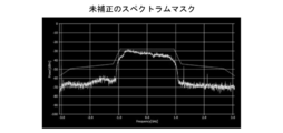
- FIG. 6A shows an observation result of the spectrum mask when neither the correction by the pre-distortion processing unit 51 nor the correction by the equalization processing unit 53 is performed.
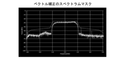
- FIG. 6B shows an observation result of the spectrum mask when both the correction by the pre-distortion processing unit 51 and the correction by the equalization processing unit 53 are performed.
- the vector correction described in FIG. 6 means correcting both the amplitude and the phase.
- FIG. 6C shows a constellation when neither the correction by the pre-distortion processing unit 51 nor the correction by the equalization processing unit 53 is performed.
- FIG. 6D shows a constellation when both the correction by the pre-distortion processing unit 51 and the correction by the equalization processing unit 53 are performed.
- EVM error vector amplitude
- the frequency converter is configured using a harmonic mixer
- the structure of the frequency converter can be simplified, and the measurement of the modulation signal can be performed using a general-purpose digital oscilloscope.
- the manufacturing cost was reduced and the measurement setup was easy.
- the output signal may include many image (false image) signals. This image signal overlaps with a frequency-converted desired signal and deteriorates modulation accuracy and the like. Although this may be a cause, deterioration of modulation accuracy and the like is prevented by correcting the waveform using the measured values of the frequency characteristics of the amplitude and phase.
- the characteristics can be easily improved by digital correction. That is, in the present embodiment, the frequency characteristics of the frequency converters 10 and 20 are grasped in advance by measurement, and are used after being digitally corrected during use. As a result, even if the feature of the device alone is not good, it is possible to perform highly accurate measurement by performing correction.
- the embodiments of the present application are not limited to the above.
- the local oscillator 40 can be integrated into the frequency converter 10 or the frequency converter 20.
- the measuring unit 3 can be configured more easily.
- the frequency converter 10, the frequency converter 20, and the local oscillator 40 may be incorporated in the arbitrary signal generator 6 or the digital oscilloscope 8.
- the prior measurement of the frequency characteristics of the amplitude and phase of the frequency converter 10 and the frequency converter 20 need not be performed every time the test article 7 is measured, and may be measured, for example, at regular intervals. Therefore, it is not always necessary to prepare a millimeter wave vector network analyzer, which is generally expensive, at the time of measurement.
- the pre-measurement data can be prepared in a plurality of measurement environments such as room temperature.
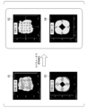
- FIG. 8 is a diagram showing another example of the comparison result of the presence or absence of correction in the present application.
- the example of FIG. 8 shows a comparison in a 60 GHz band channel, and uses 16QAM and a ⁇ / 2 BPSK signal.
- the frequency converter (down converter) 20 of FIG. 4 has a harmonic mixer, and a comparison result was obtained.
- the frequency converter (upconverter) 10 in FIG. 4 is configured not to have a harmonic mixer.
- the channel used in the comparison result of FIG. 8 is IEEE802.11ad assigned channel 1.
- 91 indicates an uncorrected constellation using 16QAM.
- the EVM was 20.6%.
- signal correction using S parameters was performed to obtain 93 constellations.
- the EVM is 8.8%, which is a great improvement.
- 92 indicates an uncorrected constellation using a ⁇ / 2 / BPSK signal.
- the EVM was 22.2%.
- signal correction using the S parameter was performed to obtain 94 constellations.
- the EVM was 7.8%, which was a significant improvement.
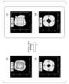
- FIG. 9 is a diagram showing still another example of the comparison result of the presence or absence of correction in the present application.
- the example of FIG. 9 shows a comparison in a 60 GHz band channel different from that in FIG. 8, and uses 16QAM and a ⁇ / 2 ⁇ BPSK signal.
- the frequency converter (down converter) 20 of FIG. 4 has a harmonic mixer, and a comparison result was obtained.
- the frequency converter (upconverter) 10 in FIG. 4 is configured not to have a harmonic mixer.
- the channel used in the comparison result of FIG. 9 is IEEE802.11ad assigned channel 2.
- reference numeral 101 denotes an uncorrected constellation using 16QAM.
- the EVM was 19.9%.
- signal correction using the S parameter was performed to obtain 103 constellations.
- the EVM is 9.0%, which is greatly improved.
- reference numeral 102 denotes an uncorrected constellation using a ⁇ / 2 BPSK signal.
- the EVM was 13.9%.
- signal correction using the S parameter was performed to obtain 104 constellations.
- the EVM of 104 was 8.4%, which was greatly improved.
- the frequency converter receives a predetermined input signal and a predetermined local oscillation signal, and receives the input signal and a harmonic signal obtained by multiplying the frequency of the local oscillation signal by n.
- a harmonic mixer wherein the input signal or the output signal is measured in advance before the input to the frequency converter or after the output from the frequency converter. Correction is performed based on the frequency characteristics of
- the frequency converter further includes a multiplier that multiplies the frequency of the local oscillation signal by k and inputs the signal to the harmonic mixer.
- the frequency converter is configured such that the measurement is performed using a vector network analyzer, and the vector network analyzer is input to the frequency converter. Generate and output the input signal, measure the frequency characteristics of the amplitude and phase of the frequency converter by inputting and measuring the output signal output from the frequency converter, and The input signal is input from the vector network analyzer to the frequency converter via an isolator or attenuator.
- the measurement system generates the first frequency converter, the second frequency converter, and a signal having the corrected waveform, and the first frequency converter.
- a signal generator for outputting to the frequency converter, a signal measuring instrument for measuring the signal output by the second frequency converter that has received the signal output from the first frequency converter, and the signal measuring instrument A correction processing unit that performs the correction on the measurement result.
- the measurement method includes: the first frequency converter; the second frequency converter; and the corrected modulation signal generated to generate the first frequency converter.
- a signal generator that outputs to the signal
- a signal measuring device that measures the signal output from the second frequency converter that has received the signal output from the first frequency converter, and a measurement result of the signal measuring instrument.
- a correction processing unit that performs the correction, a test product is inserted between the first frequency converter and the second frequency converter, and the high frequency characteristics of the test product are measured. To do.
- the mixer provided in the frequency converter can be configured by a single harmonic mixer. Therefore, the configuration can be simplified.
- This application relates to a frequency converter, a measurement system, and a measurement method.
Landscapes
- Physics & Mathematics (AREA)
- General Physics & Mathematics (AREA)
- Engineering & Computer Science (AREA)
- Power Engineering (AREA)
- Transmitters (AREA)
- Superheterodyne Receivers (AREA)
- Monitoring And Testing Of Transmission In General (AREA)
- Measuring Frequencies, Analyzing Spectra (AREA)
Abstract
所定の入力信号と、所定の局部発振信号とを入力し、入力信号と、局部発振信号の周波数をn倍した高調波信号とを混合した信号を出力信号として出力する周波数変換器であって、入力信号と、高調波信号とを混合する回路が、半導体素子の非線形特性を利用して高調波信号と入力信号とを混合する、ハーモニック・ミキサ(11)であり、入力信号又は出力信号が、当該周波数変換器への入力前に又は当該周波数変換器からの出力後に、予め計測された当該周波数変換器の振幅及び位相の周波数特性に基づき補正が施されるものである。
Description
本願は、周波数変換器、計測システム及び計測方法に関する。
本願は、2015年2月27日に、日本に出願された特願2015-39192号に基づき優先権を主張し、その内容をここに援用する。
本願は、2015年2月27日に、日本に出願された特願2015-39192号に基づき優先権を主張し、その内容をここに援用する。
現在、無線LAN(ローカルエリアネットワーク)の高速化の国際規格として検討されているIEEE802.11adでは、キャリア周波数が約60GHzであり、ミリ波の電波が使用される予定である。ここで、周波数30~300GHzの電波(電磁波)はミリ波と呼ばれ、また、3GHz~30GHzの電波はセンチメートル波と呼ばれ、ともに、周波数300MHz~3THzの電波を指すマイクロ波に含まれている。
また、IEEE802.11adでは、変調帯域が、1チャンネルあたり2.16GHzとなり、従来の帯域の10~100倍程度となる予定である。このような規格に適合したデバイスの開発を行うにあたっては、次のような手法でデバイスの特性評価が行われている。すなわち、従来の周波数帯域(例えばセンチメートル波帯)に対応する計測機器と、周波数変換器とを組み合わせることでデバイスの特性評価が行われている。ここで、周波数変換器は、例えば、ミリ波の信号をセンチメートル波にダウンコンバートしたり、センチメートル波の信号をミリ波にアップコンバートしたりする装置である。
馬 岳林、山尾 泰、赤岩 芳彦、「入力信号帯域幅に制限された情報を基に補償を行うプリディストーション非線形補償の効果」電子情報通信学会、2013-03
Yuelin MA, Yasushi YAMAO, Yoshihiko AKAIWA, "An Algorithm for Obtaining the Inverse for a Given Polynomial in Baseband," Ieice TRANS. FUNDAMENTALS, VOL.E96-A, NO.3 MARCH 2013.
秋田 米生、羽生 広、柴垣 信彦、「ミリ波通信機器の60GHz帯における周波数特性補正法の検討」電子情報通信学会、
上記のようにミリ波に対応したデバイスを評価する際には、周波数変換器を用いる場合に、次のようなことが課題となる。すなわち、上述した1チャンネルの帯域が2.16GHzとなるような変調信号を入力又は出力する周波数変換器は、非常に高価である。また、測定を行う為のセットアップが複雑であり、機器の接続間違いが発生しやすかったり、調整に時間を要したりすることがある。これらの課題が生じる原因の一つに、周波数変換器に含まれているミキサ(すなわち混合器)の構成がある。
図7は、ミリ波で使用される周波数変換器が備えるミキサの構成の一例を示している。
一般的に、ミリ波で超広帯域の変調信号を取り扱える、周波数特性が平坦な周波数変換器を製造する事は困難である。また、平坦な周波数特性を維持しての、センチメートル波からミリ波信号の直接的な生成およびミリ波からセンチメートル波信号の直接的な変換は困難である。そのため、図7に示すようなダブル・スーパー・ヘテロダイン方式の周波数変換器200を採用することが一般的である。図7に示した周波数変換器200は、異なる2種類の周波数fLO1及びfLO2を局部発振信号として入力する2個のミキサ201及び202を備えている。周波数変換器200は、アップコンバータとして使用される場合、周波数fIF1の変調信号をミキサ201へ入力し、周波数fIF1と周波数fLO1の和の値の中間周波数fIF2を持つ信号に変換される。さらに、周波数fIF2の信号をミキサ202へ入力し、周波数fIF2と周波数fLO2の和の値の周波数fRFの高周波信号に変換される。一方、ダウンコンバータとして使用される場合、周波数変換器200は、周波数fRFの高周波信号をミキサ202へ入力し、周波数fRFと周波数fLO2の差の値の中間周波数fIF2を持つ信号に変換される。さらに、周波数fIF2の信号をミキサ201へ入力し、周波数fIF2と周波数fLO1の差の値の周波数fIF1の変調信号に変換される。
一般的に、ミリ波で超広帯域の変調信号を取り扱える、周波数特性が平坦な周波数変換器を製造する事は困難である。また、平坦な周波数特性を維持しての、センチメートル波からミリ波信号の直接的な生成およびミリ波からセンチメートル波信号の直接的な変換は困難である。そのため、図7に示すようなダブル・スーパー・ヘテロダイン方式の周波数変換器200を採用することが一般的である。図7に示した周波数変換器200は、異なる2種類の周波数fLO1及びfLO2を局部発振信号として入力する2個のミキサ201及び202を備えている。周波数変換器200は、アップコンバータとして使用される場合、周波数fIF1の変調信号をミキサ201へ入力し、周波数fIF1と周波数fLO1の和の値の中間周波数fIF2を持つ信号に変換される。さらに、周波数fIF2の信号をミキサ202へ入力し、周波数fIF2と周波数fLO2の和の値の周波数fRFの高周波信号に変換される。一方、ダウンコンバータとして使用される場合、周波数変換器200は、周波数fRFの高周波信号をミキサ202へ入力し、周波数fRFと周波数fLO2の差の値の中間周波数fIF2を持つ信号に変換される。さらに、周波数fIF2の信号をミキサ201へ入力し、周波数fIF2と周波数fLO1の差の値の周波数fIF1の変調信号に変換される。
図7に示したダブルスーパーヘテロダイン方式の周波数変換器200は、ミキサを2個備えている。そのため、2種類の局部発振信号を用意しなければならない。また、ミキサ間の配線も必要となる。これらの構成が、高価格化や、測定を行う際のセットアップの複雑化、機器の接続間違いの可能性増大、調整の長時間化の一因となり得る。
従って、簡単化した構成を有する周波数変換器、計測システム及び計測方法が求められ得る。
本願は、周波数変換器、計測システム及び計測方法を提供し得る。
以下、図面を参照して本願の実施の形態について説明する。まず、図1を参照して、本願の実施形態としての周波数変換器が備えるハーモニック・ミキサの基本構成について説明する。図1は、本願の実施形態としての周波数変換器が備えるハーモニック・ミキサ100の構成例を示した図である。また、本願の実施形態は、ミリ波である超広帯域の変調信号、例えばIEEE802.11adの規格に対応する周波数帯域の信号の測定に、周波数特性が平坦な周波数変換器としてのハーモニックミキサに関するものである。また、本実施形態は、このハーモニックミキサを用いて、IEEE802.11adの規格に対応するように、ミリ波である超広帯域の変調信号を、汎用なデジタルオシロスコープを用いて簡易に測定できる測定系に関するものである。
図1に示したハーモニック・ミキサ100は、入力された局部発振信号を歪ませてその高調波を生成する回路を内部に有するミキサである。ハーモニック・ミキサ100は、周波数fLO1の局部発振信号を入力し、ミキサ内部で局部発振信号を歪ませることでのn倍の周波数n×fLO1の高調波を生成して、その周波数n×fLO1の高調波を周波数fRFの入力信号(ダウンコンバータの場合)又は周波数fIF1の入力信号(アップコンバータの場合)と混合する。
ハーモニック・ミキサ100をダウンコンバータとして用いる場合、局部発振信号を適切に選択することで、ある局部発振信号(fLO1)の高調波(n×fLO1)と入力周波数(fRF)が混合され適当な中間周波数(fIF1)の出力信号が得られる。その関係を次式で示す。nはハーモニック数と呼ばれる2以上の整数であり、高調波の次数を表す。なお、図7を参照して説明したような通常のミキサでは、高調波を用いずに周波数変換を行うのでn=1である。
fIF1=fRF-n×fLO1
一方、ハーモニック・ミキサ100をアップコンバータとして用いる場合、局部発振信号を適切に選択することで、ある局部発振信号の高調波(n×fLO1)と入力周波数(fIF1)が混合され適当な出力周波数(fRF)の出力信号が得られる。その関係を次式で示す。
fRF=fIF1+n×fLO1
次に、図2を参照して、本願の一実施形態としての周波数変換器10の構成例について説明する。図2に示した周波数変換器10は、アップコンバータとして構成されている。図2に示した周波数変換器10は、ハーモニック・ミキサ11と、ハイ・パス・フィルタ12と、パワー・アンプ(PA)13と、アイソレータ14と、逓倍器15とを備えている。
逓倍器15は、例えば、逓倍数k=2の逓倍器であり、周波数fLO1の局部発振信号を入力して周波数を2倍(すなわちk倍)し、周波数が2×fLO1(すなわちk×fLO1)の高周波信号を生成して出力信号として出力する。この逓倍器15は、本実施形態において、局部発振信号の周波数fLO1を例えば2倍とするため、アクティブダブラー(入力された信号の周波数を2倍して出力する能動的逓倍器)が用いられている。通常の逓倍器においては、出力される逓倍後の局部発振信号の電力が、逓倍する周波数によって変動する。この結果、後述するように、ハーモニック・ミキサ11の振幅および位相の周波数特性Sパラメータを測定して、周波数変換器10が出力する出力信号の補正処理を行う場合、逓倍器15の出力する局部発振信号の信号レベルが不安定のため、周波数変換器10が出力する出力信号に対して精度の高い補正ができず、正しい測定結果を得ることができない。このため、本実施形態においては、所定の周波数帯域において一定の電力の局部発振信号が出力されるように、逓倍した後の信号レベルを一定とするため、AGC(automatic gain control)のアンプ機能または、電力飽和機能が付加されており、所定の周波数帯域内における周波数のいずれにおいても信号レベル変化させずに一定の電力でハーモニック・ミキサ11に対し、逓倍した局部発振信号を出力する。
上述した逓倍器15を用いることで、局部発振信号をハーモニック・ミキサ11に供給する際の電力レベルを、広い周波数帯域において安定させ、ハーモニック・ミキサ11における変調精度及び信号レベルの再現性の各々を向上させる。これにより、周波数変換器10の振幅および位相の周波数特性(Sパラメータ)を予め測定しておき、周波数変換器10が出力する信号の補正処理を上記周波数特性により行う際、逓倍器15の出力する局部発振信号の信号レベルが周波数によらず一定のため、所定の周波数帯域における周波数のいずれにおいても周波数変換器10が出力する信号に対して精度の高い補正ができ、正しい測定結果を得ることができる。ここで、逓倍器15は、ハーモニック・ミキサ11のハーモニック数と組合わせて変更するため、任意に逓倍数を変更できる構成となっている。
ハーモニック・ミキサ11は、ハーモニック数n=2のハーモニック・ミキサであり、周波数fIF1の変調信号を入力信号として入力するとともに、逓倍器15が出力した周波数が2×fLO1の高周波信号を入力する。ハーモニック・ミキサ11は、入力した周波数(2×fLO1)の高周波信号の2倍の周波数(2×2×fLO1=4×fLO1)の高調波信号を内部で生成し、周波数fIF1の入力信号と混合する。ハーモニック・ミキサ11は、生成した周波数4×fLO1の高調波信号と周波数fIF1の入力信号とを混合することで、周波数fIF1+4×fLO1の高周波信号を生成して出力する。ハーモニック・ミキサ11の出力は、ハイ・パス・フィルタ12へ入力される。ハイ・パス・フィルタ12は、入力信号の低周波成分を減衰させて出力する。ハイ・パス・フィルタ12から出力された信号は、パワー・アンプ13で増幅され、アイソレータ14へと入力される。アイソレータ14は、高周波電力を1方向にだけ通すデバイスであり、パワー・アンプ13の出力への反射波の入力を抑制する。そして、アイソレータ14から周波数fRF=fIF1+4×fLO1の出力信号が出力される。なお、図2に示した例では逓倍数kとハーモニック数nとをどちらも2としたが、これに限らず個々に任意の値とすることができる。
ここで例えばfIF1=3GHz、fLO1=14.25GHz、逓倍数k=2、ハーモニック数n=2とすれば、出力信号の周波数fRFはfRF=fIF1+k×n×fLO1=3+2×2×14.25=60GHzとなる。この場合、周波数変換器10は、入力信号の周波数fIF1=3GHzを、周波数fRF=60GHzにアップコンバートする。
なお、アップコンバータとして構成する場合の周波数変換器10の構成は、図2に示したものに限定されず、適宜変更が可能である。例えば、ハイ・パス・フィルタ12をバンド・パス・フィルタに変更したり、各部に適宜、ロー・パス・フィルタやバンド・パス・フィルタを追加(挿入)したり、あるいはパワー・アンプ13やアイソレータ14を省略したりすることができる。また、アイソレータ14に代えてアッテネータ(高周波用減衰器)を用いることもできる。また、上記の構成では、逓倍器15を設けているので、ハーモニック・ミキサ11のハーモニック数nを逓倍数kの値に応じて小さくすることができる。ただし、逓倍器15は省略することもできる。
次に、図3を参照して、本願の一実施形態としての周波数変換器20の構成例について説明する。図3に示した周波数変換器20は、ダウンコンバータとして構成されている。図3に示した周波数変換器20は、アイソレータ21と、ロー・ノイズ・アンプ(LNA)22と、ハーモニック・ミキサ23と、ロー・パス・フィルタ24と、逓倍器25と、アッテネータ(ATT)26、プリアンプ27を備えている。
アイソレータ21は、周波数fRFの高周波信号を入力信号として入力し、出力をロー・ノイズ・アンプ22へ入力する。アイソレータ21は、入力信号の反射波の発生を抑制する。ロー・ノイズ・アンプ22は、入力信号を増幅して、ハーモニック・ミキサ23へ出力する。逓倍器25は、逓倍数k=2の逓倍器であり、周波数fLO1の局部発振信号を入力して周波数を2倍し、周波数が2×fLO1の高周波信号を生成して出力する。ハーモニック・ミキサ23は、ハーモニック数n=2のハーモニック・ミキサであり、ロー・ノイズ・アンプ22が出力した周波数fRFの高周波信号を入力するとともに、逓倍器25が出力した周波数が2×fLO1の高周波信号を入力する。ハーモニック・ミキサ23は、入力した周波数(2×fLO1)の高周波信号の2倍の周波数(2×2×fLO1=4×fLO1)の高調波信号を内部で生成し、周波数fRFの入力信号と混合する。ハーモニック・ミキサ23は、生成した周波数4×fLO1の高調波信号と周波数fRFの入力信号とを混合することで、周波数fRF-4×fLO1の高周波信号を生成して出力する。ハーモニック・ミキサ23の出力は、ロー・パス・フィルタ24へ入力される。ロー・パス・フィルタ24は、入力信号の高周波成分を減衰させる。この場合、ロー・パス・フィルタ24からは、周波数fIF1=fRF-4×fLO1の高周波信号(変調信号)が出力される。なお、図3に示した例では逓倍数kとハーモニック数nとをどちらも2としたが、これに限らず個々に任意の値とすることができる。
ここで例えばfRF=60GHz、fLO1=14.25GHz、k=2、n=2とすれば、出力信号の周波数fIF1=fRF-k×n×fLO1=60-2×2×14.25=3GHzとなる。この場合、周波数変換器20は、入力信号の周波数fRF=60GHzを、周波数fIF1=3GHzにダウンコンバートする。
なお、ダウンコンバータとして構成する場合の周波数変換器20の構成は、図3に示したものに限定されず、適宜変更が可能である。例えば、ロー・パス・フィルタ24をバンド・パス・フィルタに変更したり、各部に適宜、ハイ・パス・フィルタやバンド・パス・フィルタを追加(挿入)したり、あるいはロー・ノイズ・アンプ22やアイソレータ21を省略したりすることができる。また、アイソレータ21に代えてアッテネータを用いることもできる。また、上記の構成では、逓倍器25を設けているので、ハーモニック・ミキサ23のハーモニック数nを逓倍数kの値に応じて小さくすることができる。ただし、逓倍器25は省略することもできる。
アッテネータ26は、プリアンプ27の入力端子から反射する信号の信号レベルを減衰させ、ハーモニック・ミキサ23の出力端子において、プリアンプ27から反射されて戻ってくる信号による出力信号に対する影響を抑制する。このアッテネータ26は、ローパスフィルタ24とプリアンプ27との間に介挿されている。
プリアンプ27は、後段のデジタル・オシロスコープ(後述するデジタル・オシロスコープ8)に対し、ローパスフィルタ24からの出力信号の信号レベルを増幅して出力する。これにより、周波数変換器20からの出力信号を測定するデジタル・オシロスコープの入力の感度が低い場合でも、周波数変換器20から出力される出力信号を任意の信号レベルに増幅することができる。このため、出力信号の計測を行うデジタル・オシロスコープのダイナミックレンジに合わせて、周波数変換器20からの出力信号の信号レベルを適切に調整することが可能となる。
プリアンプ27は、後段のデジタル・オシロスコープ(後述するデジタル・オシロスコープ8)に対し、ローパスフィルタ24からの出力信号の信号レベルを増幅して出力する。これにより、周波数変換器20からの出力信号を測定するデジタル・オシロスコープの入力の感度が低い場合でも、周波数変換器20から出力される出力信号を任意の信号レベルに増幅することができる。このため、出力信号の計測を行うデジタル・オシロスコープのダイナミックレンジに合わせて、周波数変換器20からの出力信号の信号レベルを適切に調整することが可能となる。
また、周波数変換器20から出力される出力信号の信号レベルをデジタル・オシロスコープ8の感度に合わせるため、増幅器を周波数変換器20及びオシロスコープ8間に介挿した場合、この増幅器の特性が未知のため、出力信号の正しい測定結果を得ることができない。しかしながら、本実施形態のように周波数変換器20内部に対して、出力信号の信号レベルを調整するプリアンプ27を予め設けることにより、このプリアンプ27の周波数特性も、周波数変換器20の周波数特性に含めることができるため、周波数変換器20を用いることで、デジタル・オシロスコープの入力の感度に合わせて、高い精度で出力信号を測定できる測定系を簡易に構成することができる。
逓倍器25は、逓倍器15と同様に、本実施形態において局部発振信号の周波数fLO1を例えば2倍とするため、アクティブダブラーが用いられている。通常の逓倍器においては、出力される逓倍後の局部発振信号の電力が、逓倍する周波数によって変動する。この結果、後述するように周波数変換器20の振幅および位相の周波数特性(Sパラメータ)を測定して、周波数変換器20の出力する出力信号の補正処理を行う場合、逓倍器15の出力する局部発振信号の信号レベルが不安定のため、周波数変換器20が出力する出力信号に対して精度の高い補正ができず、正しい測定結果を得ることができない。このため、本実施形態においては、所定の周波数帯域において一定の電力の局部発振信号が出力されるように、逓倍した後の信号レベルを一定とするため、出力部にAGCのアンプ機能が付加されており、所定の周波数帯域における周波数のいずれにおいても信号レベルを変化させずに一定の電力でハーモニック・ミキサ23に対し、逓倍した局部発振信号を出力する。
上述した逓倍器25を用いることで、局部発振信号をハーモニック・ミキサ23に供給する際の電力レベルを、広い周波数帯域において安定させ、ハーモニック・ミキサ23における変調精度及び電力レベルの再現性の各々を向上させる。これにより、周波数変換器20の振幅および位相の周波数特性(Sパラメータ)を予め測定しておき、周波数変換器20から出力される信号の補正処理を上記周波数特性により行う際、逓倍器23の出力する局部発振信号が一定のため、所定の周波数帯域における周波数のいずれにおいても周波数変換器20が出力する信号に対して精度の高い補正ができ、正しい測定結果を得ることができる。ここで、逓倍器25は、ハーモニック・ミキサ23のハーモニック数と組合わせて変更するため、任意に逓倍数を変更できる構成となっている。
また、図1~図3に示したハーモニック・ミキサ100、11及び23の各々は、ハーモニック数nが4に限らず、2、6等でもよい。さらに、nの値は偶数に限らず、奇数としてもよい。ハーモニック・ミキサ100、11及び23の各々は、逓倍器15の逓倍数と組合わせて、ハーモニック数nの値を任意に切り替えられるように構成してもよい。
すなわち、使用するハーモニックミキサの種類によっては、その回路特性などを起因として、周波数変換を行う周波数や周波数帯域幅などにより、ハーモニック数によっては、スプリアスが発生する場合もある。このため、周波数及び周波数帯域に対応した測定や実験等を行い、ハーモニックミキサのハーモニック数を、使用するハーモニックミキサの特性に合わせて、逓倍器15の倍数との組合せも含めて、適時良好な数値として設定する必要がある。
次に、図4を参照して、本願の一実施形態としての計測システム1について説明する。図4は、本願の一実施形態としての計測システム1の構成例を示したシステム図である。なお、図4において、図2及び図3に示した構成と同一のものには同一の符号を付けている。図4に示した計測システム1は、補正用データ取得部2と、計測部3とを備えている。
計測部3は、制御部5と、任意信号発生器6と、周波数変換器10と、周波数変換器20と、デジタル・オシロスコープ8と、局部発振器40とを備えている。また、計測対象のサンプルである高周波デバイス等の試験品7は、計測時において、周波数変換器10と周波数変換器20との間に挿入される。試験品7は、例えば、アンテナ、ロー・ノイズ・アンプ等のデバイスである。これらの構成のうち、少なくとも、任意信号発生器6と、デジタル・オシロスコープ8とは、市販されている校正された計測機器であるとする。
制御部5は、例えばパーソナルコンピュータ等のコンピュータを用いて構成されている。制御部5は、プリ・ディストーション処理部51と、補正データ記憶部52と、イコライゼーション処理部53と、解析部54とを備えている。ここで、プリ・ディストーション処理部51と、イコライゼーション処理部53と、解析部54とは、制御部5を構成するコンピュータ上で、当該コンピュータのハードウェア資源を利用して実行されるソフトウェアとして構成されている。また、補正データ記憶部52は、制御部5が有する記憶装置内の所定の記憶領域として構成されている。
補正データ記憶部52は、補正用データ取得部2で取得した、周波数変換器10及び周波数変換器20の入出力信号間の振幅及び位相の変化の周波数特性(すなわち伝送特性を表す2ポートSパラメータS21)を示すデータを記録する。ただし、周波数特性を記録することに代えてあるいは記録することとともに、例えば、どのように波形を補正するかということを示すデータを記録することもできる。
プリ・ディストーション処理部51は、補正データ記憶部52に記憶されている、周波数変換器10及び周波数変換器20の振幅及び位相の周波数特性を示すデータに基づき、任意信号発生器6が発生する信号波形を補正するための処理を行う。例えば、プリ・ディストーション処理部51は、アップコンバータである周波数変換器10の振幅及び位相の周波数特性を示すデータに基づき、周波数変換器10による振幅特性のバラツキと位相特性のバラツキとを打ち消すように(すなわち周波数特性が平坦となるように)、任意信号発生器6が発生する波形の振幅値と位相値とを周波数に応じて変化させる。プリ・ディストーション処理部51は、例えば、周波数変換器10の出力信号の振幅値が他の周波数帯域と比較してある周波数帯域で減衰したような場合、その減衰分を打ち消すようにその周波数帯域で振幅値を増幅する補正を行う。また、プリ・ディストーション処理部51は、例えば、周波数変換器10の出力信号の位相が他の周波数帯域と比較してある周波数帯域で遅れたような場合、その遅れ分を打ち消すようにその周波数帯域で位相を進める補正を行う。
イコライゼーション処理部53は、デジタル・オシロスコープ8が計測及び記録した計測データに対して、補正データ記憶部52に記憶されている、周波数変換器10及び周波数変換器20の振幅及び位相の周波数特性を示すデータに基づき、補正を施す処理を行う。例えば、イコライゼーション処理部53は、ダウンコンバータである周波数変換器20の振幅及び位相の周波数特性を示すデータに基づき、周波数変換器20による振幅特性のバラツキと位相特性のバラツキとを打ち消すように(すなわち周波数特性が平坦となるように)、計測データの振幅値と位相値とを周波数に応じて変化させる。イコライゼーション処理部53は、例えば、周波数変換器20の出力信号の振幅値が他の周波数帯域と比較してある周波数帯域で減衰したような場合、その減衰分を打ち消すようにその周波数帯域で振幅値を増幅する補正を行う。また、イコライゼーション処理部53は、例えば、周波数変換器20の出力信号の位相が他の周波数帯域と比較してある周波数帯域で遅れたような場合、その遅れ分を打ち消すようにその周波数帯域で位相を進める補正を行う。
解析部54は、イコライゼーション処理部53が補正した計測データに基づき、試験品7の所定の高周波特性を解析する処理を行う。
任意信号発生器6は、任意信号発生器6が有する操作子を用いた所定の設定操作や制御部5から入力された制御信号に基づき任意の形状の波形を発生して、周波数変換器10に入力する。以下の説明では、任意信号発生器6が、中心周波数fIF1の所定の帯域幅を有する変調信号を出力するものとする。
周波数変換器10は、図2に示したようにアップコンバータとして構成されていて、任意信号発生器6が出力した周波数fIF1の信号を入力信号、局部発振器40が出力した周波数fLO1の信号を局部発振信号として入力する。そして、周波数変換器10は、周波数fIF1の入力信号と周波数fLO1の局部発振信号のk×n倍の高調波信号とを混合し、出力信号として周波数fRFの高周波信号を出力する。
周波数変換器20は、図3に示したようにダウンコンバータとして構成されていて、周波数変換器10が出力した周波数fRFの信号を例えば試験品7を介して入力信号として入力するとともに、局部発振器40が出力した周波数fLO1の信号を局部発振信号として入力する。そして、周波数変換器20は、周波数fRFの入力信号と周波数fLO1の局部発振信号のk×n倍の高調波信号とを混合し、出力信号として周波数fIF1の信号を出力する。
デジタル・オシロスコープ8は、周波数変換器20の出力信号を所定のサンプリング間隔で取り込み、内部の所定の記憶装置に記録する。
局部発振器40は、周波数fLO1の局部発振信号を発生し、例えば図示していない分配器を用いて分配し、周波数変換器10及び周波数変換器20へ入力する。
一方、補正用データ取得部2は、図2及び図3を参照して説明した周波数変換器10及び周波数変換器20の伝送特性(すなわち伝送特性を表す2ポートSパラメータS21)を試験品7の計測に先立ち、予め取得するための構成である。すなわち、補正用データ取得部2は、計測部3による試験品7の高周波特性の計測前に予め周波数変換器10及び周波数変換器20の振幅及び位相の周波数特性を計測する。
図4に示した例では、補正用データ取得部2が、ミリ波ベクトル・ネットワーク・アナライザ4を備えて構成されている。ミリ波ベクトル・ネットワーク・アナライザ4は、試験品のミリ波帯のSパラメータ等の高周波特性を計測する計測機器であり、この場合、市販の校正された装置であるとする。補正用データ取得部2では、ミリ波ベクトル・ネットワーク・アナライザ4に、アイソレータ30と、周波数変換器10又は20と、局部発振器70からなる回路が接続される。局部発振器70は、例えば局部発振器40と同じ周波数の局部発振信号を発生し、周波数変換器10又は20に対して局部発振信号として入力する。ただし、この局部発振信号はミリ波ベクトル・ネットワーク・アナライザ4から与えてもよい。周波数変換器10と周波数変換器20とは、いずれか一方ずつミリ波ベクトル・ネットワーク・アナライザ4に接続され、個々に入力信号と出力信号との間の振幅と位相の変化(すなわち伝送特性)の周波特性が計測される。
アイソレータ30は、ミリ波ベクトル・ネットワーク・アナライザ4の信号出力端子と、周波数変換器10又は20の信号入力端子との間に挿入されている。このアイソレータ30は、ミリ波ベクトル・ネットワーク・アナライザ4から出力されて周波数変換器10又は20へ入力された信号が、ミリ波ベクトル・ネットワーク・アナライザ4へ反射することを抑制する。なお、アイソレータ30に代えて、アッテネータを用いてもよい。出願人においては、このアイソレータ30等を設けることで、プリ・ディストーション処理部51とイコライゼーション処理部53とが行う波形補正の効果が向上することを確認している。
なお、周波数変換器10及び20の周波数特性を計測する際の周波数掃引の範囲は、試験品7に入力される高周波信号fRFや変調信号の帯域幅に応じて設定することができる。例えば、試験品7が、所定の無線通信に適用されるデバイスであれば、当該無線通信で使用される各チャンネルのキャリア周波数と、各チャンネルの変調信号の帯域幅とから決まる周波数範囲をカバーするように設定することができる。
ミリ波ベクトル・ネットワーク・アナライザ4を使用して計測した結果、すなわち周波数変換器10及び周波数変換器20の振幅及び位相の周波数特性(すなわち伝送特性を表す2ポートSパラメータS21)は、所定の記録媒体や所定の通信線を介して制御部5に読み込ませ、補正データ記憶部52に格納する。
次に、図4及び図5を参照して、計測システム1によって試験品7の高周波特性を計測する際の処理の流れについて説明する。
まず、ユーザが、ミリ波ベクトル・ネットワーク・アナライザ4を使用して周波数変換器10及び20の振幅および位相の周波数特性(SパラメータS21)を取得する(ステップS101)。すなわち、ハーモニックミキサを含む周波数変換器10及び20のSパラメータをミリ波ベクトル・ネットワーク・アナライザ4により予め測定する。ただし、この計測は、例えば制御部5の制御下で自動的又は半自動的に行うこともできる。
次に、ユーザによる制御部5等に対する所定の指示操作に従って、ステップS101で取得した振幅および位相の周波数特性(SパラメータS21)が補正データ記憶部52に格納される(ステップS102)。
次に、ユーザによる制御部5に対する所定の指示操作に従って、プリ・ディストーション処理部51が、補正データ記憶部52に格納されている振幅および位相の周波数特性(SパラメータS21)に基づき、任意信号発生器6で生成する波形(基準信号とする)に施すプリ・ディストーションを設定する(ステップS103)。
次に、ユーザが、周波数変換器(アップコンバータ)10と周波数変換器(ダウンコンバータ)20とを直接(すなわち最短の導波管等を介して)接続し、ユーザが、直接あるいは制御部5を介して所定の指示操作を行うことで、任意信号発生器6で発生した補正された基準信号を周波数変換器(アップコンバータ)10へ入力し、周波数変換器(ダウンコンバータ)20の出力をデジタル・オシロスコープ8で計測して記録する(ステップS104)。この周波数変換器(アップコンバータ)10の出力端子(例えば導波管の挿入口として形成されている)と、周波数変換器(ダウンコンバータ)20の入力端子(例えば導波管の挿入口として形成されている)とが、試験品7のミリ波帯の高周波特性を計測する際の基準面(ミリ波基準面とする)となる。また、ミリ波基準面を基準として図に向かって左側が送信側(すなわちアップコンバーション動作)であり、ミリ波基準面を基準として図に向かって右側が受信側(すなわちダウンコンバーション動作)である。
次に、ユーザが、周波数変換器(アップコンバータ)10と周波数変換器(ダウンコンバータ)20との間に試験品7を挿入し、ユーザが、直接あるいは制御部5を介して所定の指示操作を行うことで、任意信号発生器6で発生した補正された基準信号を周波数変換器(アップコンバータ)10へ入力し、周波数変換器(ダウンコンバータ)20の出力をデジタル・オシロスコープ8が測定して記録する(ステップS105)。
次に、ユーザによる制御部5に対する所定の指示操作に従って、イコライゼーション処理部53が、デジタル・オシロスコープ8で記録されたデータに対して、補正データ記憶部52に格納されている振幅および位相の周波数特性(SパラメータS21)に基づき補正処理(すなわちイコライゼーション処理)を施す(ステップS106)。ここでは、例えばステップS104で記録された計測値と、ステップS105で記録された計測値の双方に対して補正処理が行われる。
次に、ユーザによる制御部5に対する所定の指示操作に従って、解析部54が、イコライゼーション処理部53によって補正処理されたデータに基づき例えばコンステレーション(変調精度)、スペクトラムマスク等を算出する処理を行う(ステップS107)。ここで、試験品7の高周波特性は、ステップS104で計測してさらにステップS106で補正した計測値における振幅や位相変化の値(あるいはインピーダンス、歪み量、各種パラメータ)を基準値として、その基準値からステップS105で計測してステップS106で補正した計測値における振幅や位相変化の値(あるいはインピーダンス、歪み量、各種パラメータ)がどれだけ変化したのかということに基づいて、解析結果を算出することができる。すなわち、ステップS104で計測したミリ波基準面の計測値(あるいはこれを補正したもの)を基準として、ステップS105で計測した試験品7の計測値(あるいはこれを補正したもの)の解析を行うことができる。
次に、図6A~Dを参照して、プリ・ディストーション処理部51による送信側での周波数変換器10への入力信号に対する振幅と位相の補正と、イコライゼーション処理部53による受信側での周波数変換器20からの出力信号に対する振幅と位相の補正との効果の確認結果について説明する。図6Aは、プリ・ディストーション処理部51による補正と、イコライゼーション処理部53による補正とをいずれも行わなかった場合のスペクトラムマスクの観測結果である。一方、図6Bは、プリ・ディストーション処理部51による補正と、イコライゼーション処理部53による補正とを両方行った場合のスペクトラムマスクの観測結果である。ここで図6に記載したベクトル補正とは、振幅と位相の両者を補正することを意味している。
また、図6Cは、プリ・ディストーション処理部51による補正と、イコライゼーション処理部53による補正とをいずれも行わなかった場合のコンステレーションである。一方、図6Dは、プリ・ディストーション処理部51による補正と、イコライゼーション処理部53による補正とを両方行った場合のコンステレーションである。EVM(エラー ベクトル振幅)の値は、補正を行わなかった場合に23.9%であるのに対して、補正を行った場合に8.1%となっており、変調精度の改善が確認された。
以上のように、本願の実施形態では、周波数変換器をハーモニック・ミキサを用いて構成したので、周波数変換器の構造を簡素化することができ、汎用的なデジタルオシロスコープを用いて変調信号の測定を行うため、製造コストの低下や測定セットアップのし易さを達成することができた。また、ハーモニック・ミキサを用いた場合、出力信号には多くのイメージ(偽像)信号を含んでしまう場合があり、このイメージ信号は、周波数変換された所望の信号と重なり合い変調精度等を悪化させる原因となることがあるが、振幅と位相の周波数特性の計測値を用いて波形を補正することで変調精度等の悪化を防止している。よって、仮に単体では周波数特性があまり良好ではない周波数変換器であっても、デジタル補正により特性を容易に改善することができる。すなわち、本実施形態においては、周波数変換器10及び20の周波数特性を予め計測により把握しておき、使用の際にデジタル補正を行って使用する。これらにより、仮にデバイス単体としての素性が良好でなくとも補正を施す事で、精度の高い計測を行うことができる。
なお、本願の実施の形態は、上記のものに限定されない。例えば、周波数変換器10や周波数変換器20に、局部発振器40を一体として組み込むことができる。局部発振器40を周波数変換器10や周波数変換器20に組み込むことにより、より簡易に計測部3を構成することができる。また、周波数変換器10や周波数変換器20、局部発振器40を、任意信号発生器6に組み込んだり、デジタル・オシロスコープ8に組み込んだりしてもよい。また、周波数変換器10や周波数変換器20についての振幅と位相の周波数特性の事前計測は、試験品7の測定の度に行う必要は無く、例えば、一定の期間ごとに計測すればよい。したがって、一般に高価であるミリ波ベクトルネットワークアナライザは、計測の際、常に用意する必要はない。また、事前計測のデータは、室温等の複数の計測環境において用意しておくこともできる。
また、図8は、本願における補正の有無の比較結果の他の一例を示した図である。図8の例は、60GHz帯のチャネルにおける比較を示すもので、16QAMと、π/2 BPSK信号を用いている。図8では、図4の周波数変換器(ダウンコンバータ)20がハーモニック・ミキサを有する構成として、比較結果を得た。ただし、図4における周波数変換器(アップコンバータ)10については、ハーモニック・ミキサを有さない構成とした。なお、図8の比較結果において使用したチャネルは、IEEE802.11adの割り当てチャネル1である。
図8において、91は、16QAMを用いた未補正のコンステレーションを示している。EVMは20.6%であった。これに対してSパラメータを用いた信号補正を行い、93のコンステレーションを得た。93のコンステレーションでは、EVMが8.8%であり、大きく改善されている。
図8において、92は、π/2 BPSK信号を用いた未補正のコンステレーションを示している。EVMは22.2%であった。これに対してSパラメータを用いた信号補正を行い、94のコンステレーションを得た。94のコンステレーションでは、EVMが7.8%であり、大きく改善された。
図8から理解されるように、図4の周波数変換器(ダウンコンバータ)20のみがハーモニック・ミキサを有する構成とした場合であっても、EVMを大きく改善することができた。
図9は、本願における補正の有無の比較結果の更に他の一例を示した図である。図9の例は、図8とは異なる60GHz帯のチャネルにおける比較を示すもので、16QAMと、π/2 BPSK信号を用いている。図9では、図4の周波数変換器(ダウンコンバータ)20がハーモニック・ミキサを有する構成として、比較結果を得た。ただし、図4における周波数変換器(アップコンバータ)10については、ハーモニック・ミキサを有さない構成とした。なお、図9の比較結果において使用したチャネルは、IEEE802.11adの割り当てチャネル2である。
図9において、101は、16QAMを用いた未補正のコンステレーションを示している。EVMは19.9%であった。これに対してSパラメータを用いた信号補正を行い、103のコンステレーションを得た。103のコンステレーションでは、EVMが9.0%であり、大きく改善されている。
図9において、102は、π/2 BPSK信号を用いた未補正のコンステレーションを示している。EVMは13.9%であった。これに対してSパラメータを用いた信号補正を行い、104のコンステレーションを得た。104のEVMは8.4%であり、大きく改善された。
図9から理解されるように、図4の周波数変換器(ダウンコンバータ)20のみがハーモニック・ミキサを有する構成とした場合であっても、EVMを大きく改善することができた。図8と図9では、それぞれ異なるチャネルを用いたが、いずれにおいれもEVMが大きく改善された。
なお、上記の他にも、本願には、いくつかの例示的な態様があり得る。第1の例示的な態様において、周波数変換器は、所定の入力信号と、所定の局部発振信号とを入力し、前記入力信号と、前記局部発振信号の周波数をn倍した高調波信号とを混合した信号を出力信号として出力する周波数変換器であって、前記入力信号と、前記高調波信号とを混合する回路が、半導体素子の非線形特性を利用して前記高調波信号と前記入力信号とを混合する、ハーモニック・ミキサであり、前記入力信号又は前記出力信号が、当該周波数変換器への入力前に又は当該周波数変換器からの出力後に、予め計測された当該周波数変換器の振幅及び位相の周波数特性に基づき補正が施されるものである。
また、第2の例示的な態様において、周波数変換器は、さらに前記局部発振信号の周波数をk倍逓倍し、その信号を前記ハーモニック・ミキサへ入力する逓倍器を備える。
また、第3の例示的な態様において、周波数変換器は、前記計測が、ベクトル・ネットワーク・アナライザを用いて行われるものであり、前記ベクトル・ネットワーク・アナライザが、前記周波数変換器へ入力される前記入力信号を生成して出力し、前記周波数変換器から出力された前記出力信号を入力して計測することで、前記周波数変換器の振幅及び位相の周波数特性を計測するものであり、かつ、前記入力信号が、前記ベクトル・ネットワーク・アナライザから、アイソレータ又はアッテネータを介して、前記周波数変換器へ入力される。
また、第4の例示的な態様において、計測システムは、第1の前記周波数変換器と、第2の前記周波数変換器と、前記補正を施した波形を有する信号を発生して、前記第1の周波数変換器へ出力する信号発生器と、前記第1の周波数変換器から出力された信号を受信した前記第2の周波数変換器が出力した信号を計測する信号計測器と、前記信号計測器の計測結果に対して、前記補正を施す補正処理部と、を備える。
また、第5の例示的な態様において、計測方法は、第1の前記周波数変換器と、第2の前記周波数変換器と、前記補正した変調信号を発生して、前記第1の周波数変換器へ出力する信号発生器と、前記第1の周波数変換器から出力された信号を受信した前記第2の周波数変換器が出力した信号を計測する信号計測器と、前記信号計測器の計測結果に対して、前記補正を行う補正処理部と、を用いて、前記第1の周波数変換器と、前記第2の周波数変換器との間に試験品を挿入し、前記試験品の高周波特性を計測する。
上記の実施形態等によれば、周波数変換器が備えるミキサを、1個のハーモニック・ミキサで構成することができる。よって、構成を簡単化することができる。
本願は、周波数変換器、計測システム及び計測方法に関する。
1…計測システム、2…補正用データ取得部、3…計測部、4…ミリ波ベクトル・ネットワーク・アナライザ、5…制御部、6…任意信号発生器、8…デジタル・オシロスコープ、10…周波数変換器、11…ハーモニック・ミキサ、20…周波数変換器、23…ハーモニック・ミキサ、30…アイソレータ、40…局部発振器、51…プリ・ディストーション処理部、52…補正データ記憶部、53…イコライゼーション処理部、54…解析部、81…ダイオード、91~94…コンステレーション、101~104…コンステレーション
Claims (6)
- 所定の入力信号と、所定の局部発振信号とを入力し、前記入力信号と、前記局部発振信号の周波数をn倍した高調波信号とを混合した信号を出力信号として出力する周波数変換器であって、
前記入力信号と、前記高調波信号とを混合する回路が、半導体素子の非線形特性を利用して前記高調波信号と前記入力信号とを混合する、ハーモニック・ミキサであり、
前記入力信号又は前記出力信号が、当該周波数変換器への入力前に又は当該周波数変換器からの出力後に、予め計測された当該周波数変換器の振幅及び位相の周波数特性に基づき補正が施されるものである、
ことを特徴とする周波数変換器。 - さらに前記局部発振信号の周波数をk倍逓倍し、その信号を前記ハーモニック・ミキサへ入力する逓倍器を備えている、
ことを特徴とする請求項1に記載の周波数変換器。 - 前記逓倍器が出力段に可変利得アンプまたは飽和機能を有する手段を有している
ことを特徴とする請求項2に記載の周波数変換器。 - 前記計測が、ベクトル・ネットワーク・アナライザを用いて行われるものであり、
前記ベクトル・ネットワーク・アナライザが、前記周波数変換器へ入力される前記入力信号を生成して出力し、前記周波数変換器から出力された前記出力信号を入力して計測することで、前記周波数変換器の振幅及び位相の周波数特性を計測するものであり、かつ、
前記入力信号が、前記ベクトル・ネットワーク・アナライザから、アイソレータ又はアッテネータを介して、前記周波数変換器へ入力される、
ことを特徴とする請求項1から請求項3のいずれか一項に記載の周波数変換器。 - 請求項1から請求項4のいずれか一項に記載の周波数変換器である、第1及び第2の周波数変換器と、
前記補正を施した波形を有する信号を発生して、前記第1の周波数変換器へ出力する信号発生器と、
前記第1の周波数変換器から出力された信号を受信した前記第2の周波数変換器が出力した信号を計測する信号計測器と、
前記信号計測器の計測結果に対して、前記補正を施す補正処理部と、
を備える計測システム。 - 請求項1から請求項4のいずれか一項に記載の周波数変換器である、第1及び第2の周波数変換器と、
前記補正した変調信号を発生して、前記第1の周波数変換器へ出力する信号発生器と、
前記第1の周波数変換器から出力された信号を受信した前記第2の周波数変換器が出力した信号を計測する信号計測器と、
前記信号計測器の計測結果に対して、前記補正を行う補正処理部と、
を用いて、
前記第1の周波数変換器と、前記第2の周波数変換器との間に試験品を挿入し、前記試験品の高周波特性を計測する、
計測方法。
Priority Applications (5)
| Application Number | Priority Date | Filing Date | Title |
|---|---|---|---|
| EP16755691.9A EP3249807B1 (en) | 2015-02-27 | 2016-02-26 | Frequency converter, measuring system, and measuring method |
| CN201680011804.9A CN107251416B (zh) | 2015-02-27 | 2016-02-26 | 变频器、测量系统和测量方法 |
| FIEP16755691.9T FI3249807T3 (fi) | 2015-02-27 | 2016-02-26 | Taajuusmuuttaja, mittausjärjestelmä ja mittausmenetelmä |
| US15/553,365 US10649013B2 (en) | 2015-02-27 | 2016-02-26 | Frequency converter, measuring system, and measuring method |
| PL16755691.9T PL3249807T3 (pl) | 2015-02-27 | 2016-02-26 | Przetwornica częstotliwości, system pomiarowy, i sposób pomiaru |
Applications Claiming Priority (2)
| Application Number | Priority Date | Filing Date | Title |
|---|---|---|---|
| JP2015039192A JP6611441B2 (ja) | 2014-02-28 | 2015-02-27 | 周波数変換ユニット、計測システム及び計測方法 |
| JP2015-039192 | 2015-02-27 |
Publications (1)
| Publication Number | Publication Date |
|---|---|
| WO2016136947A1 true WO2016136947A1 (ja) | 2016-09-01 |
Family
ID=56789974
Family Applications (1)
| Application Number | Title | Priority Date | Filing Date |
|---|---|---|---|
| PCT/JP2016/055825 Ceased WO2016136947A1 (ja) | 2015-02-27 | 2016-02-26 | 周波数変換器、計測システム及び計測方法 |
Country Status (7)
| Country | Link |
|---|---|
| US (1) | US10649013B2 (ja) |
| EP (1) | EP3249807B1 (ja) |
| JP (1) | JP6611441B2 (ja) |
| CN (1) | CN107251416B (ja) |
| FI (1) | FI3249807T3 (ja) |
| PL (1) | PL3249807T3 (ja) |
| WO (1) | WO2016136947A1 (ja) |
Cited By (1)
| Publication number | Priority date | Publication date | Assignee | Title |
|---|---|---|---|---|
| US10649013B2 (en) | 2015-02-27 | 2020-05-12 | Tokyo Metropolitan Industrial Technology Research Institute | Frequency converter, measuring system, and measuring method |
Families Citing this family (9)
| Publication number | Priority date | Publication date | Assignee | Title |
|---|---|---|---|---|
| JP6933604B2 (ja) * | 2018-04-24 | 2021-09-08 | アンリツ株式会社 | 位相特性校正装置及び位相特性校正方法 |
| CN108988962B (zh) * | 2018-07-25 | 2021-09-10 | 北京无线电计量测试研究所 | 一种宽带矢量调制信号误差矢量幅度的修正装置与方法 |
| CN109298318B (zh) * | 2018-10-24 | 2024-06-21 | 伟创力电子技术(苏州)有限公司 | V/e波段毫米波电路板测试系统及控制方法 |
| US11579176B2 (en) | 2019-12-30 | 2023-02-14 | Industrial Technology Research Institute | Sensing system and sensing signal measuring method thereof |
| TWI705251B (zh) * | 2019-12-30 | 2020-09-21 | 財團法人工業技術研究院 | 感測系統及其感測訊號量測方法 |
| US11762086B2 (en) * | 2021-03-02 | 2023-09-19 | GM Global Technology Operations LLC | Generating a high frequency FMCW radar from low frequency FMCW radar |
| CN113315475B (zh) * | 2021-05-28 | 2023-05-09 | 中电科思仪科技股份有限公司 | 一种太赫兹宽带下变频装置及其工作方法 |
| CN114050871B (zh) * | 2021-11-11 | 2023-12-05 | 北京天地一格科技有限公司 | 一种w波段信号测试方法 |
| WO2025075195A1 (ja) * | 2023-10-06 | 2025-04-10 | 7Gaa株式会社 | 減衰特性測定装置及び減衰特性測定方法 |
Citations (5)
| Publication number | Priority date | Publication date | Assignee | Title |
|---|---|---|---|---|
| WO2002029426A1 (fr) * | 2000-10-02 | 2002-04-11 | Advantest Corporation | Procede de mesure a balayage a conversion de frequence |
| JP2002340950A (ja) * | 2001-05-14 | 2002-11-27 | Anritsu Corp | 半導体デバイステストシステム |
| JP2003344464A (ja) * | 2002-05-31 | 2003-12-03 | Yokogawa Electric Corp | 周波数信号測定装置 |
| JP2005295097A (ja) * | 2004-03-31 | 2005-10-20 | Eudyna Devices Inc | ハーモニックミキサ及びこれを備えた無線装置 |
| JP2007150935A (ja) * | 2005-11-30 | 2007-06-14 | Sharp Corp | リミッタ付ミキサ、周波数変換装置、通信装置、及びマルチチップモジュール |
Family Cites Families (44)
| Publication number | Priority date | Publication date | Assignee | Title |
|---|---|---|---|---|
| JPS5764171A (en) * | 1980-10-08 | 1982-04-19 | Advantest Corp | Spectrum analyzer |
| US4703433A (en) * | 1984-01-09 | 1987-10-27 | Hewlett-Packard Company | Vector network analyzer with integral processor |
| US5184093A (en) * | 1991-03-08 | 1993-02-02 | Mitsubishi Denki Kabushiki Kaisha | Frequency synthesizer |
| JPH05121949A (ja) * | 1991-10-26 | 1993-05-18 | Nec Corp | 周波数変換器 |
| JPH11127476A (ja) | 1997-10-24 | 1999-05-11 | Kobe Steel Ltd | 無線通信システム |
| US6065137A (en) * | 1998-04-06 | 2000-05-16 | Hewlett-Packard Company | Network analyzer measurement method using adaptive signal processing |
| JP4005703B2 (ja) | 1998-07-09 | 2007-11-14 | 三井造船株式会社 | アレイアンテナの送受信方法および周波数逓倍方式ミリ波二次元映像装置 |
| DE19926454C2 (de) * | 1999-06-10 | 2002-02-28 | Rohde & Schwarz | Vektorieller Netzwerkanalysator |
| GB9921813D0 (en) * | 1999-09-16 | 1999-11-17 | Mitel Semiconductor Ltd | Frequency converter and radio frequency tuner |
| WO2001063750A1 (en) * | 2000-02-24 | 2001-08-30 | Fraunhofer-Gesellschaft zur Förderung der angewandten Forschung e.V. | System for reducing adjacent-channel interference by pre-linearization and pre-distortion |
| GB2382662B (en) * | 2001-11-29 | 2003-12-10 | Univ Cardiff | High frequency circuit analyzer |
| DE10246700B4 (de) * | 2002-10-07 | 2009-10-15 | Rohde & Schwarz Gmbh & Co. Kg | Meßvorrichtung, insbesondere vektorieller Netzwerkanalysator, mit getrennten Oszillatoren |
| US7187916B2 (en) * | 2003-02-07 | 2007-03-06 | Broadcom Corporation | Method and system for measuring receiver mixer IQ mismatch |
| US20110025296A1 (en) * | 2003-07-24 | 2011-02-03 | Mesuro Limited | High Frequency Circuit Analyser |
| GB2404257B (en) * | 2003-07-24 | 2006-07-19 | Univ Cardiff | High frequency circuit analyser |
| US7061222B2 (en) * | 2003-10-22 | 2006-06-13 | Agilent Technologies, Inc. | Automated testing of frequency converter device |
| DE602005020003D1 (de) * | 2004-06-07 | 2010-04-29 | Nmdg Nv | Echtzeit-einrichtungscharakterisierung und -analyse |
| CN1331310C (zh) * | 2005-04-11 | 2007-08-08 | 南京理工大学 | 基于三支线合成网络的高功率毫米波上变频功放组件 |
| US7231311B2 (en) * | 2005-04-19 | 2007-06-12 | Jan Verspecht | Method for characterizing high-frequency mixers |
| DE102005037353A1 (de) * | 2005-08-08 | 2007-02-15 | Rohde & Schwarz Gmbh & Co. Kg | Messvorrichtung, insbesondere vektorieller Netzwerkanalysator, mit Phasenregelung |
| DE102006017018A1 (de) * | 2006-01-10 | 2007-07-12 | Rohde & Schwarz Gmbh & Co. Kg | Secum-Trahenz-Verfahren, insbesondere für einen Netzwerkanalysator |
| US7826816B2 (en) * | 2006-07-11 | 2010-11-02 | Qualcomm Incorporated | Systems, methods, and apparatus for frequency conversion |
| US8155904B2 (en) * | 2007-10-05 | 2012-04-10 | Dvorak Steven L | Vector signal measuring system, featuring wide bandwidth, large dynamic range, and high accuracy |
| US8548091B2 (en) * | 2007-12-21 | 2013-10-01 | Apple Inc. | Measuring and correcting errors in a transmit chain with an IQ up-converter and IQ down-converter |
| CN102077099B (zh) * | 2008-04-21 | 2013-07-10 | 安特维尔塔-Mw有限公司 | 具有注入信号确定的开环负载牵引装置 |
| GB2466028A (en) * | 2008-12-08 | 2010-06-09 | Univ Cardiff | High frequency measurement system |
| JP4758483B2 (ja) * | 2009-01-15 | 2011-08-31 | シャープ株式会社 | 電子装置 |
| DE102009011795A1 (de) * | 2009-03-05 | 2010-09-09 | Rohde & Schwarz Gmbh & Co. Kg | Synthesizer mit einstellbarer, stabiler und reproduzierbarer Phase und Frequenz |
| WO2010119569A1 (ja) | 2009-04-17 | 2010-10-21 | キヤノンアネルバ株式会社 | 周波数変換装置、及び周波数変換方法 |
| GB2470781A (en) * | 2009-06-05 | 2010-12-08 | Mesuro Ltd | High frequency measurement with load pull |
| EP2440944B1 (en) | 2009-06-12 | 2019-06-12 | National Instruments Ireland Resources Limited | System and method for representing a multi-tone signal |
| WO2012002023A1 (ja) * | 2010-06-29 | 2012-01-05 | 日本電気株式会社 | 周波数変換器およびそれを用いた受信機 |
| JP2012063336A (ja) | 2010-09-16 | 2012-03-29 | Keycom Corp | サブミリ波放射計 |
| CA2837334C (en) * | 2011-06-01 | 2022-05-10 | Andrew Llc | Broadband distributed antenna system with non-duplexer isolator sub-system |
| JP5566974B2 (ja) * | 2011-08-29 | 2014-08-06 | 株式会社東芝 | 信号生成回路、発振装置、レーダー装置 |
| US9214718B2 (en) * | 2012-03-08 | 2015-12-15 | Apple Inc. | Methods for characterizing tunable radio-frequency elements |
| DE102013200033B4 (de) * | 2012-10-10 | 2023-06-15 | Rohde & Schwarz GmbH & Co. Kommanditgesellschaft | Verfahren und System zur Bestimmung von Streuparametern eines frequenzumsetzenden Messobjekts |
| US8824594B2 (en) * | 2012-11-05 | 2014-09-02 | Mstar Semiconductor, Inc. | Digital frequency modulation aided AMPM predistortion digital transmitter |
| GB2516410B (en) * | 2013-03-22 | 2020-08-12 | Plymouth Rock Tech Inc | Scanning apparatus |
| US10042029B2 (en) * | 2013-04-16 | 2018-08-07 | Keysight Technologies, Inc. | Calibration of test instrument over extended operating range |
| EP3025424B1 (en) * | 2013-07-22 | 2017-07-12 | Telefonaktiebolaget LM Ericsson (publ) | A frequency converter |
| CN103595404B (zh) | 2013-10-29 | 2017-07-11 | 中国电子科技集团公司第四十一研究所 | 一种混频器群时延测量电路及方法 |
| JP6611441B2 (ja) | 2014-02-28 | 2019-11-27 | 地方独立行政法人東京都立産業技術研究センター | 周波数変換ユニット、計測システム及び計測方法 |
| US9484861B1 (en) * | 2015-11-24 | 2016-11-01 | King Fahd University Of Petroleum And Minerals | Method for system level oriented load-pull-based envelope tracking power amplifiers |
-
2015
- 2015-02-27 JP JP2015039192A patent/JP6611441B2/ja active Active
-
2016
- 2016-02-26 EP EP16755691.9A patent/EP3249807B1/en active Active
- 2016-02-26 WO PCT/JP2016/055825 patent/WO2016136947A1/ja not_active Ceased
- 2016-02-26 CN CN201680011804.9A patent/CN107251416B/zh active Active
- 2016-02-26 US US15/553,365 patent/US10649013B2/en active Active
- 2016-02-26 FI FIEP16755691.9T patent/FI3249807T3/fi active
- 2016-02-26 PL PL16755691.9T patent/PL3249807T3/pl unknown
Patent Citations (5)
| Publication number | Priority date | Publication date | Assignee | Title |
|---|---|---|---|---|
| WO2002029426A1 (fr) * | 2000-10-02 | 2002-04-11 | Advantest Corporation | Procede de mesure a balayage a conversion de frequence |
| JP2002340950A (ja) * | 2001-05-14 | 2002-11-27 | Anritsu Corp | 半導体デバイステストシステム |
| JP2003344464A (ja) * | 2002-05-31 | 2003-12-03 | Yokogawa Electric Corp | 周波数信号測定装置 |
| JP2005295097A (ja) * | 2004-03-31 | 2005-10-20 | Eudyna Devices Inc | ハーモニックミキサ及びこれを備えた無線装置 |
| JP2007150935A (ja) * | 2005-11-30 | 2007-06-14 | Sharp Corp | リミッタ付ミキサ、周波数変換装置、通信装置、及びマルチチップモジュール |
Non-Patent Citations (1)
| Title |
|---|
| See also references of EP3249807A4 * |
Cited By (1)
| Publication number | Priority date | Publication date | Assignee | Title |
|---|---|---|---|---|
| US10649013B2 (en) | 2015-02-27 | 2020-05-12 | Tokyo Metropolitan Industrial Technology Research Institute | Frequency converter, measuring system, and measuring method |
Also Published As
| Publication number | Publication date |
|---|---|
| JP2015180060A (ja) | 2015-10-08 |
| CN107251416B (zh) | 2021-06-15 |
| EP3249807A1 (en) | 2017-11-29 |
| CN107251416A (zh) | 2017-10-13 |
| FI3249807T3 (fi) | 2025-01-13 |
| US10649013B2 (en) | 2020-05-12 |
| PL3249807T3 (pl) | 2025-02-03 |
| EP3249807A4 (en) | 2019-01-09 |
| US20180246151A1 (en) | 2018-08-30 |
| EP3249807B1 (en) | 2024-10-09 |
| JP6611441B2 (ja) | 2019-11-27 |
Similar Documents
| Publication | Publication Date | Title |
|---|---|---|
| JP6611441B2 (ja) | 周波数変換ユニット、計測システム及び計測方法 | |
| US8204456B2 (en) | Systems and methods for spurious emission cancellation | |
| US8411730B2 (en) | Semiconductor integrated communication circuit and operation method thereof | |
| US9749172B2 (en) | Calibration method and calibration apparatus for calibrating mismatch between first signal path and second signal path of transmitter/receiver | |
| US20100007355A1 (en) | Method for testing radio frequency (rf) receiver to provide power correction data | |
| US8867596B2 (en) | Methods and apparatuses of calibrating I/Q mismatch in communication circuit | |
| US20110051791A1 (en) | Methods and Systems for Calibrating for Gain and Phase Imbalance and Local Oscillator Feed-Through | |
| Kim et al. | Parametric method of frequency-dependent I/Q imbalance compensation for wideband quadrature modulator | |
| JP2008102133A (ja) | Rfシステムの補正方法及びrf受信器 | |
| CN114487685B (zh) | 具有高精度校准功能的信号分析仪及其高精度校准方法 | |
| US11063623B2 (en) | Baseband corrector for RF non-linearity in zero-IF receiver | |
| US11664906B2 (en) | Method for calibrating transmitter | |
| Spindelberger et al. | Improving the performance of direct-conversion SDRs for radiated precompliance measurements | |
| US11757479B2 (en) | Enhancing TX-TX isolation through digital pre-compensation | |
| US20100178891A1 (en) | Method and circuit for calibrating analog circuit components | |
| CN115219867B (zh) | 矢量误差幅度测量装置和测量方法、终端及存储介质 | |
| JP4923276B2 (ja) | 周波数変換装置の周波数応答の特徴付け方法 | |
| Singh et al. | Power calibration methods for frequency extenders aided modulated measurements at sub-THz/THz | |
| US20260063694A1 (en) | Methods and apparatus for component/system testing under modulated signals using frequency extenders | |
| JP7758619B2 (ja) | 無線伝送装置 | |
| CN113676433B (zh) | 发送iq失配校准的方法和装置 | |
| Quispe et al. | Design and Characterization of a 24 GHz Transceiver with Adaptative Power Control for 5 G mmWave Systems | |
| CN118138155A (zh) | W波段宽带矢量调制信号的空口校准系统和方法 | |
| He | New Amplitude Correction and Phase Linearization Technique for Channel Response on Wideband Microwave Spectrum Analysers | |
| JP2016131324A (ja) | 電気特性測定装置及び測定システム |
Legal Events
| Date | Code | Title | Description |
|---|---|---|---|
| 121 | Ep: the epo has been informed by wipo that ep was designated in this application |
Ref document number: 16755691 Country of ref document: EP Kind code of ref document: A1 |
|
| REEP | Request for entry into the european phase |
Ref document number: 2016755691 Country of ref document: EP |
|
| WWE | Wipo information: entry into national phase |
Ref document number: 15553365 Country of ref document: US |
|
| NENP | Non-entry into the national phase |
Ref country code: DE |