WO2016139736A1 - 冷凍サイクル装置の制御装置及び方法 - Google Patents
冷凍サイクル装置の制御装置及び方法 Download PDFInfo
- Publication number
- WO2016139736A1 WO2016139736A1 PCT/JP2015/056122 JP2015056122W WO2016139736A1 WO 2016139736 A1 WO2016139736 A1 WO 2016139736A1 JP 2015056122 W JP2015056122 W JP 2015056122W WO 2016139736 A1 WO2016139736 A1 WO 2016139736A1
- Authority
- WO
- WIPO (PCT)
- Prior art keywords
- coefficient
- flow rate
- refrigerant
- expansion valve
- unit
- Prior art date
- Legal status (The legal status is an assumption and is not a legal conclusion. Google has not performed a legal analysis and makes no representation as to the accuracy of the status listed.)
- Ceased
Links
Images


Classifications
-
- F—MECHANICAL ENGINEERING; LIGHTING; HEATING; WEAPONS; BLASTING
- F25—REFRIGERATION OR COOLING; COMBINED HEATING AND REFRIGERATION SYSTEMS; HEAT PUMP SYSTEMS; MANUFACTURE OR STORAGE OF ICE; LIQUEFACTION SOLIDIFICATION OF GASES
- F25B—REFRIGERATION MACHINES, PLANTS OR SYSTEMS; COMBINED HEATING AND REFRIGERATION SYSTEMS; HEAT PUMP SYSTEMS
- F25B49/00—Arrangement or mounting of control or safety devices
- F25B49/02—Arrangement or mounting of control or safety devices for compression type machines, plants or systems
-
- F—MECHANICAL ENGINEERING; LIGHTING; HEATING; WEAPONS; BLASTING
- F25—REFRIGERATION OR COOLING; COMBINED HEATING AND REFRIGERATION SYSTEMS; HEAT PUMP SYSTEMS; MANUFACTURE OR STORAGE OF ICE; LIQUEFACTION SOLIDIFICATION OF GASES
- F25B—REFRIGERATION MACHINES, PLANTS OR SYSTEMS; COMBINED HEATING AND REFRIGERATION SYSTEMS; HEAT PUMP SYSTEMS
- F25B41/00—Fluid-circulation arrangements
- F25B41/30—Expansion means; Dispositions thereof
- F25B41/31—Expansion valves
- F25B41/34—Expansion valves with the valve member being actuated by electric means, e.g. by piezoelectric actuators
- F25B41/35—Expansion valves with the valve member being actuated by electric means, e.g. by piezoelectric actuators by rotary motors, e.g. by stepping motors
-
- F—MECHANICAL ENGINEERING; LIGHTING; HEATING; WEAPONS; BLASTING
- F25—REFRIGERATION OR COOLING; COMBINED HEATING AND REFRIGERATION SYSTEMS; HEAT PUMP SYSTEMS; MANUFACTURE OR STORAGE OF ICE; LIQUEFACTION SOLIDIFICATION OF GASES
- F25B—REFRIGERATION MACHINES, PLANTS OR SYSTEMS; COMBINED HEATING AND REFRIGERATION SYSTEMS; HEAT PUMP SYSTEMS
- F25B13/00—Compression machines, plants or systems, with reversible cycle
-
- F—MECHANICAL ENGINEERING; LIGHTING; HEATING; WEAPONS; BLASTING
- F25—REFRIGERATION OR COOLING; COMBINED HEATING AND REFRIGERATION SYSTEMS; HEAT PUMP SYSTEMS; MANUFACTURE OR STORAGE OF ICE; LIQUEFACTION SOLIDIFICATION OF GASES
- F25B—REFRIGERATION MACHINES, PLANTS OR SYSTEMS; COMBINED HEATING AND REFRIGERATION SYSTEMS; HEAT PUMP SYSTEMS
- F25B2313/00—Compression machines, plants or systems with reversible cycle not otherwise provided for
- F25B2313/031—Sensor arrangements
- F25B2313/0314—Temperature sensors near the indoor heat exchanger
-
- F—MECHANICAL ENGINEERING; LIGHTING; HEATING; WEAPONS; BLASTING
- F25—REFRIGERATION OR COOLING; COMBINED HEATING AND REFRIGERATION SYSTEMS; HEAT PUMP SYSTEMS; MANUFACTURE OR STORAGE OF ICE; LIQUEFACTION SOLIDIFICATION OF GASES
- F25B—REFRIGERATION MACHINES, PLANTS OR SYSTEMS; COMBINED HEATING AND REFRIGERATION SYSTEMS; HEAT PUMP SYSTEMS
- F25B2313/00—Compression machines, plants or systems with reversible cycle not otherwise provided for
- F25B2313/031—Sensor arrangements
- F25B2313/0315—Temperature sensors near the outdoor heat exchanger
-
- F—MECHANICAL ENGINEERING; LIGHTING; HEATING; WEAPONS; BLASTING
- F25—REFRIGERATION OR COOLING; COMBINED HEATING AND REFRIGERATION SYSTEMS; HEAT PUMP SYSTEMS; MANUFACTURE OR STORAGE OF ICE; LIQUEFACTION SOLIDIFICATION OF GASES
- F25B—REFRIGERATION MACHINES, PLANTS OR SYSTEMS; COMBINED HEATING AND REFRIGERATION SYSTEMS; HEAT PUMP SYSTEMS
- F25B2500/00—Problems to be solved
- F25B2500/19—Calculation of parameters
-
- F—MECHANICAL ENGINEERING; LIGHTING; HEATING; WEAPONS; BLASTING
- F25—REFRIGERATION OR COOLING; COMBINED HEATING AND REFRIGERATION SYSTEMS; HEAT PUMP SYSTEMS; MANUFACTURE OR STORAGE OF ICE; LIQUEFACTION SOLIDIFICATION OF GASES
- F25B—REFRIGERATION MACHINES, PLANTS OR SYSTEMS; COMBINED HEATING AND REFRIGERATION SYSTEMS; HEAT PUMP SYSTEMS
- F25B2600/00—Control issues
- F25B2600/02—Compressor control
- F25B2600/025—Compressor control by controlling speed
- F25B2600/0253—Compressor control by controlling speed with variable speed
-
- F—MECHANICAL ENGINEERING; LIGHTING; HEATING; WEAPONS; BLASTING
- F25—REFRIGERATION OR COOLING; COMBINED HEATING AND REFRIGERATION SYSTEMS; HEAT PUMP SYSTEMS; MANUFACTURE OR STORAGE OF ICE; LIQUEFACTION SOLIDIFICATION OF GASES
- F25B—REFRIGERATION MACHINES, PLANTS OR SYSTEMS; COMBINED HEATING AND REFRIGERATION SYSTEMS; HEAT PUMP SYSTEMS
- F25B2600/00—Control issues
- F25B2600/25—Control of valves
- F25B2600/2513—Expansion valves
-
- F—MECHANICAL ENGINEERING; LIGHTING; HEATING; WEAPONS; BLASTING
- F25—REFRIGERATION OR COOLING; COMBINED HEATING AND REFRIGERATION SYSTEMS; HEAT PUMP SYSTEMS; MANUFACTURE OR STORAGE OF ICE; LIQUEFACTION SOLIDIFICATION OF GASES
- F25B—REFRIGERATION MACHINES, PLANTS OR SYSTEMS; COMBINED HEATING AND REFRIGERATION SYSTEMS; HEAT PUMP SYSTEMS
- F25B2700/00—Sensing or detecting of parameters; Sensors therefor
- F25B2700/19—Pressures
- F25B2700/193—Pressures of the compressor
- F25B2700/1931—Discharge pressures
-
- F—MECHANICAL ENGINEERING; LIGHTING; HEATING; WEAPONS; BLASTING
- F25—REFRIGERATION OR COOLING; COMBINED HEATING AND REFRIGERATION SYSTEMS; HEAT PUMP SYSTEMS; MANUFACTURE OR STORAGE OF ICE; LIQUEFACTION SOLIDIFICATION OF GASES
- F25B—REFRIGERATION MACHINES, PLANTS OR SYSTEMS; COMBINED HEATING AND REFRIGERATION SYSTEMS; HEAT PUMP SYSTEMS
- F25B2700/00—Sensing or detecting of parameters; Sensors therefor
- F25B2700/19—Pressures
- F25B2700/193—Pressures of the compressor
- F25B2700/1933—Suction pressures
-
- F—MECHANICAL ENGINEERING; LIGHTING; HEATING; WEAPONS; BLASTING
- F25—REFRIGERATION OR COOLING; COMBINED HEATING AND REFRIGERATION SYSTEMS; HEAT PUMP SYSTEMS; MANUFACTURE OR STORAGE OF ICE; LIQUEFACTION SOLIDIFICATION OF GASES
- F25B—REFRIGERATION MACHINES, PLANTS OR SYSTEMS; COMBINED HEATING AND REFRIGERATION SYSTEMS; HEAT PUMP SYSTEMS
- F25B2700/00—Sensing or detecting of parameters; Sensors therefor
- F25B2700/21—Temperatures
- F25B2700/2104—Temperatures of an indoor room or compartment
-
- F—MECHANICAL ENGINEERING; LIGHTING; HEATING; WEAPONS; BLASTING
- F25—REFRIGERATION OR COOLING; COMBINED HEATING AND REFRIGERATION SYSTEMS; HEAT PUMP SYSTEMS; MANUFACTURE OR STORAGE OF ICE; LIQUEFACTION SOLIDIFICATION OF GASES
- F25B—REFRIGERATION MACHINES, PLANTS OR SYSTEMS; COMBINED HEATING AND REFRIGERATION SYSTEMS; HEAT PUMP SYSTEMS
- F25B2700/00—Sensing or detecting of parameters; Sensors therefor
- F25B2700/21—Temperatures
- F25B2700/2115—Temperatures of a compressor or the drive means therefor
- F25B2700/21152—Temperatures of a compressor or the drive means therefor at the discharge side of the compressor
-
- Y—GENERAL TAGGING OF NEW TECHNOLOGICAL DEVELOPMENTS; GENERAL TAGGING OF CROSS-SECTIONAL TECHNOLOGIES SPANNING OVER SEVERAL SECTIONS OF THE IPC; TECHNICAL SUBJECTS COVERED BY FORMER USPC CROSS-REFERENCE ART COLLECTIONS [XRACs] AND DIGESTS
- Y02—TECHNOLOGIES OR APPLICATIONS FOR MITIGATION OR ADAPTATION AGAINST CLIMATE CHANGE
- Y02B—CLIMATE CHANGE MITIGATION TECHNOLOGIES RELATED TO BUILDINGS, e.g. HOUSING, HOUSE APPLIANCES OR RELATED END-USER APPLICATIONS
- Y02B30/00—Energy efficient heating, ventilation or air conditioning [HVAC]
- Y02B30/70—Efficient control or regulation technologies, e.g. for control of refrigerant flow, motor or heating
Definitions
- the present invention relates to a control apparatus and method for a refrigeration cycle apparatus that controls the opening degree of an expansion valve.
- Patent Document 1 corrects by multiplying the deviation between the discharge temperature and the set discharge temperature and the deviation between the refrigerant temperature and the target refrigerant temperature by a correction coefficient according to the current value of the operating frequency (load magnitude) of the compressor. It is disclosed that a subsequent deviation is derived, and the capacity of the compressor and the opening of the electric expansion valve are derived based on the derived corrected deviation.
- the opening degree of the expansion valve is derived based on the discharge temperature as in Patent Document 1
- the deviation of the control object such as the opening degree of the expansion valve and the proportional operation and integration of a predetermined control cycle interval for calculating this deviation
- the proportional operation and the integration operation are corrected at the same ratio.
- the change range in which the proportional operation changes in the entire load range from the minimum load to the maximum load does not necessarily match the change range in which the integral operation changes.
- the present invention has been made to solve the above-described problems, and controls a refrigeration cycle apparatus that can improve the responsiveness of the discharge temperature of the compressor over a wide load range and suppress the deterioration of energy saving performance.
- An object is to provide an apparatus and method.
- a control apparatus for a refrigeration cycle apparatus is a control apparatus for a refrigeration cycle apparatus including a refrigerant circuit in which a compressor, a condenser, an expansion valve, and an evaporator are connected by a refrigerant pipe, and is discharged from the compressor.
- Valve controller for outputting an opening degree command of the expansion valve based on a discharge temperature deviation between the discharge temperature of the refrigerant to be set and the set discharge temperature, and at least two kinds of control parameters of a proportional coefficient and an integral coefficient, and a refrigerant
- a flow rate correction coefficient calculation unit that calculates a flow rate correction coefficient from a refrigerant flow rate circulating in the circuit and a preset flow rate reference value, and a proportional coefficient is calculated by correcting the flow rate correction coefficient from a preset proportional coefficient reference value.
- a coefficient correction unit that calculates an integration coefficient by correcting with a flow rate correction coefficient from a preset integration coefficient reference value, and the coefficient correction unit includes a change range of the integration coefficient in a change range of the refrigerant flow rate. To be greater than the variation range of the proportional coefficient, and calculates a proportional and integral coefficients.
- the ratio between the maximum value and the minimum value of the change range of the integral coefficient is the maximum value and the minimum value of the change range of the proportional coefficient.
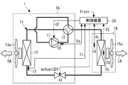
- FIG. 1 is a refrigerant circuit diagram showing an embodiment of a control device for a refrigeration cycle apparatus according to the present invention.
- the refrigeration cycle apparatus 1 controls the operation of the refrigeration cycle apparatus 1.
- the refrigeration cycle apparatus 1 includes a refrigerant in which an outdoor unit 1A and an indoor unit 1B are connected via a refrigerant pipe 2.
- a circuit 1x is configured.
- a refrigerant that can be gas-liquid two-phase within a use temperature and pressure range such as a fluorocarbon, hydrocarbon, or carbon dioxide is used.
- HFC refrigerants such as R410A, R407C, and R404A, HCFC refrigerants such as R22 and R134a, and natural refrigerants such as helium may be used.
- the indoor unit 1 ⁇ / b> B has an indoor heat exchanger 15 connected to the flow path switch 12 and the expansion valve 14.
- the compressor 11 pumps the refrigerant in a compressed vapor state to increase the temperature and pressure, and is composed of, for example, an inverter compressor whose capacity can be controlled by the rotational speed or the operating frequency.
- the operation of the compressor 11 is controlled by the control device 20.
- the compressor 11 and the flow path switch 12 may be installed not on the outdoor unit 1A side but on the indoor unit 1B side.
- the expansion valve 14 may be installed not on the outdoor unit 1A side but on the indoor unit 1B side.
- the outdoor unit 1A and the indoor unit 1B are not separated and may be formed integrally.
- the flow path switch 12 is composed of, for example, a four-way valve, and switches the refrigerant flow path according to the operation mode.
- the flow path switch 12 connects the discharge side of the compressor 11 and the indoor unit 1 ⁇ / b> B, and connects the outdoor heat exchanger 13 and the suction side of the compressor 11.
- the flow path switch 12 connects the discharge side of the compressor 11 and the outdoor heat exchanger 13 and also connects the indoor unit 1 ⁇ / b> B and the suction side of the compressor 11 during the cooling operation.
- the outdoor heat exchanger 13 is composed of, for example, a fin-and-tube heat exchanger that performs heat exchange between the refrigerant flowing through the refrigerant pipe and the outdoor air OA passing between the fins.
- One of the outdoor heat exchangers 13 is connected to the flow path switch 12 and the other is connected to the expansion valve 14.
- the outdoor heat exchanger 13 functions as a heat absorber (evaporator) during heating operation, and functions as a radiator (condenser) during cooling operation.
- the outdoor heat exchanger 13 is supplied with outdoor air OA supplied from the outdoor fan 13a.
- the expansion valve 14 is composed of, for example, an electronic expansion valve having a variable opening, and expands a high-pressure liquid-phase refrigerant into the gas-liquid mixed phase to lower the temperature and pressure.
- the opening degree of the expansion valve 14 is controlled by the control device 20.
- the indoor side heat exchanger 15 is composed of, for example, a fin-and-tube heat exchanger that performs heat exchange between the refrigerant flowing through the refrigerant pipe and the indoor air IA passing between the fins.
- the indoor heat exchanger 15 functions as a radiator (condenser) during heating operation, and functions as a heat absorber (evaporator) during cooling operation.
- the indoor air IA supplied from the indoor fan 15a is blown to the indoor heat exchanger 15.
- the high-temperature and high-pressure refrigerant discharged from the compressor 11 flows into the outdoor heat exchanger 13 that functions as a condenser, is heat-exchanged with the outdoor air OA, dissipates heat, and is condensed. Become a liquid refrigerant. Thereafter, the refrigerant that has become high-pressure liquid refrigerant becomes a low-temperature and low-pressure refrigerant that has been decompressed and gas-liquid two-phased in the expansion valve 14 and flows into the indoor heat exchanger 15 that functions as an evaporator.
- the refrigerant flowing into the indoor heat exchanger 15 is heat-exchanged with the indoor air IA, absorbs heat and evaporates, and the indoor air IA is cooled. Thereafter, the refrigerant that has flowed out of the indoor heat exchanger 15 passes through the flow path switch 12 and flows into the suction side of the compressor 11.
- the high-temperature and high-pressure refrigerant discharged from the compressor 11 flows into the indoor side heat exchanger 15 functioning as a condenser, is heat-exchanged with the indoor air IA, dissipates heat, and is condensed. Becomes a high-pressure liquid refrigerant.
- the indoor air IA is heated by heat radiation from the refrigerant.
- the liquid refrigerant is decompressed through the expansion valve 14, becomes a low-temperature and low-pressure refrigerant that is gas-liquid two-phased, and flows into the outdoor heat exchanger 13 that functions as a condenser.
- the refrigerant flowing into the outdoor heat exchanger 13 is heat-exchanged with the outdoor air OA, absorbs heat and evaporates, becomes a low-temperature and low-pressure gas refrigerant, and the refrigerant flowing out from the indoor-side heat exchanger 15 switches the flow path. It flows into the suction side of the compressor 11 through the compressor 12.
- the refrigeration cycle apparatus 1 uses the condensation and evaporation of the refrigerant in the refrigerant circuit 1x to radiate heat absorbed from one of the outdoor air OA and the indoor air IA to the other to perform cooling or heating. . At this time, heat can be efficiently transferred between the outdoor air OA and the indoor air IA through the refrigerant as compared with the power required for the compression of the compressor 11.
- the operation of the refrigeration cycle apparatus 1 is controlled by the control device 20.
- the control device 20 may be provided on the outdoor unit 1A side, may be provided on the indoor unit 1B side, may be provided separately from the outdoor unit 1A and the indoor unit 1B, and may be provided outdoors. Functions may be provided separately in the unit 1A and the indoor unit 1B as appropriate.
- Various sensors are installed in the refrigeration cycle apparatus 1, and the control device 20 controls the operation of the refrigeration cycle apparatus 1 based on information detected by the various sensors.
- the refrigeration cycle apparatus 1 is provided on the discharge side of the compressor 11 and detects the discharge temperature Td of the refrigerant discharged from the compressor 11 and the outdoor heat exchanger 13 and the expansion.
- the first refrigerant temperature sensor 17 that detects the temperature T1 of the refrigerant flowing between the valve 14 and the refrigerant temperature T2 in the gas-liquid two-phase state or the liquid phase position in the indoor heat exchanger 15 is detected.
- a second refrigerant temperature sensor 18 that detects the room temperature Tr of the room air.
- the refrigerant temperature T1 detected by the first refrigerant temperature sensor 17 is substantially similar to the condensation temperature Tc when the outdoor heat exchanger 13 functions as a condenser, and the outdoor heat exchanger 13 is an evaporator. Is substantially similar to the evaporation temperature Te.
- the refrigerant temperature T2 detected by the second refrigerant temperature sensor 18 is substantially similar to the condensation temperature Tc when the indoor heat exchanger 15 functions as a condenser, and the indoor heat exchanger 15 is an evaporator. Is substantially similar to the evaporation temperature Te.
- the control device 20 Based on the set room temperature Trset, the room temperature Tr, the discharge temperature Td, and the discharge temperatures T1 and T2 that are input and commanded from a remote controller (not shown) or the like, the control device 20 sends the rotational speed command CF to the compressor 11 and the expansion valve 14.
- the opening degree command actual LEV is calculated and output.
- the control device 20 has a function of controlling the flow path switch 12 in order to change the rotational speed of the outdoor fan 13a, the rotational speed of the indoor fan 15a, or the circulation direction of the refrigerant in accordance with the operating state of the refrigeration cycle apparatus 1. Have.
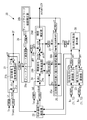
- FIG. 2 is a functional block diagram showing an example of the control device of the refrigeration cycle apparatus of FIG. 1, and the control device 20 will be described with reference to FIG.
- the configuration of the control device 20 shown in FIG. 2 is constructed by executing a program on hardware such as a microcomputer.
- FIG. 3 is a block diagram showing an example of a limiting controller in the control device of FIG.
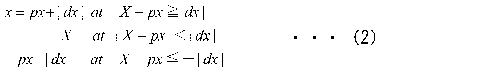
- Each of the change rate limiters LAGa to LAGp in FIG. 3 calculates the output x based on the following equations (1) and (2), where X is an input.
- Equation (1) dt is a control cycle
- T is a delay time constant
- dx in equations (1) and (2) is an output change during the control cycle dt
- px is the immediately preceding control cycle (the “immediately preceding control cycle” is An output in the meaning of “time before one control cycle” with respect to the current time (hereinafter, the same expression is also used)
- Equation (2) is an example of a differential expansion equation as a first-order lag calculator of the change rate limiters LAGa to LAGp. Note that the delay time constants T in the change rate limiters LAGa to LAGp may be different from each other.
- the compressor control unit 21 outputs a rotation speed command CF for controlling the rotation speed of the compressor 11. Specifically, the compressor controller 21 calculates a difference between the set room temperature trset and the room temperature tr, a difference calculator 21a, and a rotation speed change command dCF based on the difference calculated by the difference calculator 21a.
- a rotation change command calculation unit 21b and a rotation number command calculation unit 21c that calculates a rotation number command CF from the rotation number change command dCF calculated by the rotation change command calculation unit 21b are provided.
- the compressor control unit 21 performs the following various calculations every control cycle dt.
- the difference calculation unit 21a receives the set room temperature trset after the set room temperature Trset has passed through the change rate limiter LAGa and the room temperature tr after the room temperature Tr has passed through the change rate limiter LAGb.
- the set room temperature Trset is input to the control device 20 from, for example, a remote controller.
- the difference calculating unit 21a calculates a room temperature deviation dtr based on the set room temperature trset and the room temperature tr by the following equation (3).
- the rotation change command calculation unit 21b calculates a rotation speed change command dCF indicating the amount of change in the rotation speed of the compressor 11 using the room temperature deviation dtr calculated by the difference calculation unit 21a.
- the unit 21 includes a PI controller (P: proportional, I: integral) having a proportional coefficient Kpcf which is two kinds of control parameters and an integral coefficient Kicf of the compressor control unit 21.
- the rotation change command calculation unit 21b calculates a rotation speed change command dCF based on the following equation (4).
- Expression (4) is a developed expression as a speed PI controller, pdtr is a room temperature deviation calculated in the immediately preceding control cycle, the first term on the right side of Expression (4) is a proportional action, The second term is the integration operation.
- the rotation change command calculation unit 21b uses the room temperature deviation pdtr calculated in the immediately preceding control cycle in addition to the room temperature deviation dtr in the proportional operation, and uses the room temperature deviation dtr in the integral operation to rotate every control cycle dt.
- the number change command dCF is calculated.
- the rotation speed command calculation unit 21c changes the rotation speed of the current control cycle calculated by the rotation change command calculation unit 21b (“current control cycle” is used to mean “current time”, and the same applies hereinafter).
- the rotation speed command pCF to the compressor 11 in the immediately preceding control cycle is added to the command dCF to calculate the rotation speed command CF to the compressor 11 in the current control cycle. That is, the rotational speed command calculation unit 21c calculates and outputs the rotational speed command CF as shown in the following formula (5).
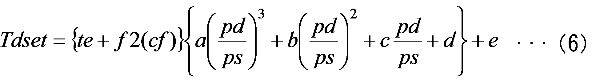
- the discharge temperature setting unit 22 uses the rotation speed command cf calculated by the compressor control unit 21, the discharge pressure Pd and the suction pressure Ps of the compressor 11, and the set discharge temperature of the refrigerant discharged from the compressor 11. tdset is calculated, and the calculation result is set as a set value of the expansion valve control unit 24.
- the discharge temperature setting unit 22 calculates the set discharge temperature Tdset using the following equation (6). In the discharge temperature setting unit 22, the rotation speed command CF, the discharge pressure pd, and the suction pressure ps after the rotation speed command CF, the discharge pressure Pd, and the suction pressure Ps pass through the change rate limiters LAGc, LAGd, and LAGe, respectively. Entered.
- Expression (6) illustrates the case where the expansion ratio (pd / ps) is a cubic expression, but even a higher-order or lower-order expression or another function using an expansion ratio or the like may be used.
- the function f2 in the equation (6) is a function indicating the relationship between the rotational speed command cf and the superheat temperature (superheat temperature), in which the influence of the configuration of the refrigerant circuit 1x is incorporated.
- the function f2 is exemplified as a linear expression of the rotational speed command cf using a2 and b2 as coefficients.
- the function f2 is a higher-order expression or a lower-order expression, or a separate expression using the rotational speed command cf. It may be a function of
- the discharge pressure Pd and the suction pressure Ps may be directly detected using a pressure sensor, but the control device 20 determines the refrigerant discharge pressure Pd and the refrigerant pressure in the compressor 11 from the condensation temperature Tc and the evaporation temperature Te.
- a temperature / pressure converter 23 for calculating the suction pressure Ps is provided.
- the temperature-pressure conversion unit 23 includes a discharge pressure calculation unit 23a that calculates the discharge pressure Pd from the condensation temperature tc, and an intake pressure calculation unit 23b that calculates the discharge pressure Pd from the condensation temperature tc.
- the discharge pressure calculation unit 23a calculates the discharge pressure Pd of the compressor 11 from the condensation temperature tc after the condensation temperature Tc passes through the change rate limiter LAGf, based on the following formula (7).
- the suction pressure calculation unit 23b calculates the suction pressure Ps of the compressor 11 from the evaporation temperature te after the evaporation temperature Te passes through the change rate limiter LAGg based on the following equation (8).
- f1 is a temperature-pressure characteristic function of the refrigerant, and is a function for calculating the saturation pressure at the temperature of the refrigerant. Further, a1, b1, c1, and d1 indicate coefficients of the temperature-pressure characteristic function f1.
- the temperature-pressure characteristic function f1 is exemplified as a cubic equation, but the discharge pressure Pd and the suction pressure Ps can be calculated from the condensation temperature tc and the evaporation temperature te. Any known method such as a higher-order or lower-order expression or another function can be applied.
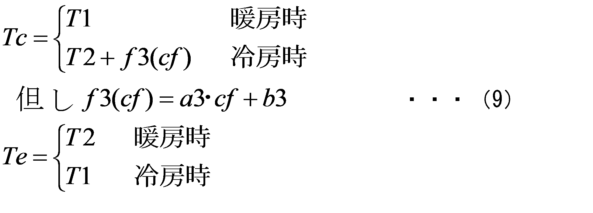
- the temperature-pressure conversion unit 23 is derived from the refrigerant temperatures T1 and T2 detected by the first refrigerant temperature sensor 17 and the second refrigerant temperature sensor 18 using, for example, the following equation (9).
- condensation temperature Tc and the evaporation temperature Te may be derived by another formula other than the formula (9).
- the function f3 in the equation (9) is a function that incorporates the influence of the configuration of the refrigerant circuit 1x and indicates the relationship between the rotational speed command cf and the supercooling temperature (subcooling temperature).
- the rotation with coefficients a3 and b3 is used.
- a linear expression of the number command cf is used, a higher order or lower order expression or another function may be used.
- the expansion valve control unit 24 includes a discharge deviation calculation unit 24a, an opening change command calculation unit 24b, and an opening command calculation unit 24c.
- the discharge deviation calculating unit 24a is configured so that the set discharge temperature Tdset after the set discharge temperature Tdset passes through the change rate limiter LAGh and the discharge temperature Td detected by the discharge sensor 16 are changed.
- a discharge temperature deviation dtd with respect to the discharge temperature td after passing through the limiter LAGI is calculated.
- the delay time constant T of the change rate limiter LAGh is preferably in units of minutes (about 2 minutes) and preferably larger than the delay time constant of other first-order delays (about 10 seconds).
- the opening change command calculator 24b calculates the opening change command dLEV using the discharge temperature deviation dtd calculated by the discharge deviation calculator 24a.
- the proportional change kp which is two types of control parameters, It consists of a PI controller with an integration coefficient ki.
- the opening change command calculation unit 24b calculates the opening change command dLEV using the following equation (11).
- Expression (11) is a developed expression as a speed PI controller, where the first term on the right side is a proportional operation and the second term on the right side is an integral operation.
- the proportional operation in addition to the discharge temperature deviation dtd, the control immediately before The discharge temperature deviation pdd of the cycle is used, and in the integral operation, the discharge temperature deviation dtd is used and the opening change command dLEV is calculated.
- the proportional coefficient kp and the integral coefficient ki in the equation (11) are calculated by the coefficient correction unit 25.
- the proportional correction coefficient RKp is exemplified as a function including only one term of the proportional correction multiplier NKp power of the flow rate correction coefficient rf.
- the coefficient a4 , B4 and c4 may be a polynomial, another function, or a function using a fixed multiplier value other than the proportional correction multiplier Nkp.
- An integration coefficient Ki is calculated from the coefficient reference value Kibase.
- the integral correction coefficient RKi is exemplified as a function consisting of only one term of the flow correction coefficient rf to the NKi power.
- the coefficients a5, b5, It may be a polynomial using c5 and d5, another function, or a function using a fixed multiplier value other than the integral correction multiplier Nki.
- the proportional correction coefficient RKp and the integral correction coefficient RKi are expressed by the above formula ( 12), (12a), (13), and functions other than those exemplified in (13a) may be used.
- the proportionality coefficient Kp calculated by the proportionality coefficient correction unit 25a becomes the proportionality coefficient kp after passing through the change rate limiter LAGj, and is input to the opening change command calculation unit 24b.
- the integration coefficient Ki calculated in the integration coefficient correction unit 25b becomes the integration coefficient ki after passing through the change rate limiter LAGk, and is input to the opening change command calculation unit 24b.
- the coefficient correction unit 25 has a change range of the integral coefficient Ki (for example, a ratio between the maximum value and the minimum value) in a change range of the refrigerant flow rate (for example, a ratio between the maximum value and the minimum value).
- the opening command calculation unit 24c opens based on the opening change command dLEV in the current control cycle calculated in the opening change command calculation unit 24b and the opening command pLEV to the expansion valve 14 in the immediately preceding control cycle.
- the degree command LEV is calculated. Further, as shown in the following formula (14), the opening degree command calculation unit 24c adds the feedforward amount ff calculated by the feedforward unit 26, and the opening degree command to the expansion valve 14 in the current control cycle. LEV is calculated. Note that the feedforward amount dff after the feedforward amount dFF passes through the change rate limiter LAGl is input to the opening degree command calculation unit 24c.
- the feedforward unit 26 is composed of a high-pass filter, for example, and includes a feedforward calculation unit 26a and a feedforward coefficient correction unit 26b.
- a delay time constant Tff is set in advance to the feedforward calculation unit 26a, and the rotation speed command cf after the rotation speed command CF passes through the change rate limiter LAGc is input.
- the feedforward calculating part 26a outputs the feedforward amount dFF added to the opening degree instruction
- Equation (15) is the simplest differential expansion equation of the high-pass filter
- kff is the feedforward proportional coefficient
- pFF is the feedforward integration amount in the immediately preceding control cycle.
- the feedforward integration amount FF in the current control cycle can be expressed as the following equation (16).
- the feedforward proportional coefficient kff is a value after the feedforward proportional coefficient Kff calculated by the feedforward coefficient correction unit 26b passes through the change rate limiter LAGm.
- the feed forward proportional coefficient Kff is calculated using the correction coefficient RKff and the feed forward proportional reference value Kffbase.
- the feedforward proportional correction coefficient RKff is illustrated as a case where it is obtained as the power of the flow rate correction coefficient rf to the NKff power, but other formulas and flow rate correction coefficients as exemplified in Formulas (12a) and (13a) Other functions using rf may be used.
- the opening degree command LEV may be calculated without adding the feedforward amount ff in the above formula (14).
- the followability of the discharge temperature Td to the set discharge temperature Tdset is deteriorated, or the discharge temperature deviation dtd temporarily increases when a load change occurs.
- the expansion valve control unit 24 includes an opening degree correction unit 24d that corrects the opening degree command LEV calculated by the opening degree command calculation unit 24c in accordance with the actual characteristics of the expansion valve 14.
- the opening degree correcting unit 24d is linear when the relationship between the opening degree command LEV calculated by the opening degree command calculating unit 24c and the refrigerant flow rate flow passing through the expansion valve 14 is non-linear. Correct so that it becomes a relationship.
- the opening degree correction unit 24d corrects the opening degree command LEV to the corrected opening degree actual LEV based on the following formulas (18) and (19).
- FIG. 4 is a graph showing an example of a relationship between an opening degree command proportional to the refrigerant flow rate and a corrected opening degree command.
- the expansion valve 14 has a non-linear relationship in which the rate of increase (inclination) of the opening degree command LEV with respect to the corrected opening degree command actual LEV changes in the middle.
- the opening correction unit 24d defines an inverse function f0 ⁇ 1 for each region having a different slope, and calculates a corrected opening command actualLEV that corrects the opening command LEV based on the equation (19).
- the opening correction is performed if the expansion valve 14 has a linear relationship.
- the part 24d is not necessary.
- the flow rate correction coefficient calculating unit 27 calculates a flow rate correction coefficient from the refrigerant flow rate circulating in the refrigerant circuit 1x and a preset flow rate reference value.
- the flow rate of the refrigerant circulating through the refrigerant circuit 1x increases as the opening degree of the expansion valve 14 opens. Therefore, the flow rate correction coefficient calculating unit 27 calculates the flow rate correction coefficient Rf using the opening degree command LEV calculated by the opening degree command calculating unit 24c as a parameter indicating the refrigerant flow rate.
- correction is performed using the opening command reference value LEVbase which is also a flow rate reference value.
- the opening command reference value LEVbase is an opening command of the expansion valve 14 at the reference point of the steady state refrigerant flow rate, and is preset in the flow rate correction coefficient calculation unit 27 as a flow rate reference value. Specifically, the flow rate correction coefficient calculation unit 27 calculates the flow rate correction coefficient Rf based on the following equation (20).
- the opening degree command lev after the opening degree command LEV passes through the change rate limiter LAGo is used as a parameter indicating the refrigerant flow rate before correction.
- the pressure correction coefficient rp in the equation (20) indicates that the flow rate of refrigerant flowing through the expansion valve 14 depends not only on the opening degree of the expansion valve 14 but also on the discharge pressure of the compressor 11, so that the opening degree command lev of the expansion valve 14 This is for correcting the flow rate correction coefficient Rf with the refrigerant flow rate as the pressure (strictly, the pressure difference before and after the expansion valve 14).
- the pressure correction coefficient rp in the equation (20) is calculated by the pressure correction coefficient calculation unit 28.
- the flow rate correction coefficient calculating unit 27 calculates the flow rate correction coefficient Rf based on the equation (20) using the pressure correction coefficient rp after the pressure correction coefficient Rp passes through the change rate limiter LAGp.
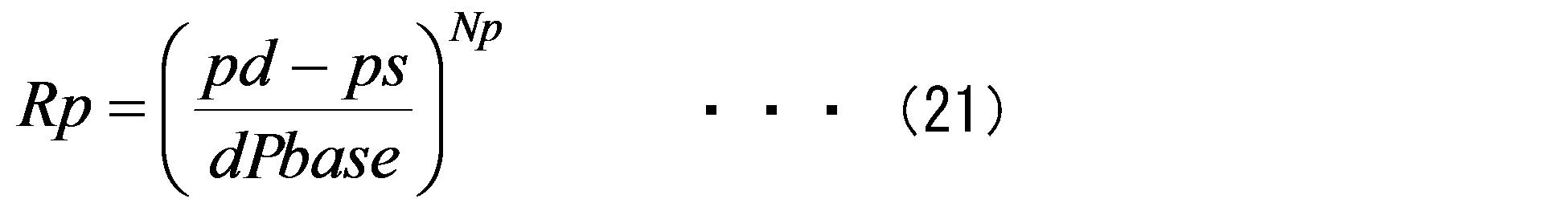
- the pressure correction coefficient calculator 28 calculates a pressure correction coefficient Rp based on the following equation (21) from the discharge pressure pd and the suction pressure ps estimated using the condensation temperature Tc and the evaporation temperature Te.
- the pressure correction coefficient calculation unit 28 receives the discharge pressure pd after the discharge pressure Pd has passed through the change rate limiter LAGe, and the suction pressure ps has the suction pressure ps after having passed through the change rate limiter LAGd. Entered.
- dPbase is a pressure difference reference value corresponding to the reference refrigerant flow rate
- Np is a pressure correction multiplier (for example, 1/2)
- the pressure difference reference value dPbase and the pressure correction multiplier Np are pressure correction coefficients. It is preset in the calculation unit 28.
- the flow rate correction coefficient calculation unit 27 calculates the flow rate correction coefficient Rf using the pressure correction coefficient Rp, so that the flow rate correction coefficient Rf can be calculated with high accuracy. That is, when the flow rate correction coefficient Rf is calculated using only the opening degree command lev, the opening degree command lev may differ from the actual refrigerant flow rate and may be inaccurate. For example, even when the opening degree command lev is a predetermined value, the flow rate of refrigerant passing through the expansion valve 14 is ideal when the pressure difference before and after the expansion valve 14 becomes four times the predetermined pressure from the predetermined pressure. In fact, it increases by a factor of two. As described above, when the refrigerant flow rate is set only by the opening degree command lev, it may be inaccurate.
- the flow rate correction coefficient calculation unit 27 calculates the flow rate correction coefficient Rf using the pressure correction coefficient Rp as shown in the equation (20).
- a flow rate correction coefficient Rf taking pressure correction into consideration is calculated using a flow rate correction coefficient lev / LEVbase and a pressure correction coefficient rp in which only the opening degree command lev to the expansion valve 14 is a refrigerant flow rate.
- the flow rate correction coefficient Rf is corrected by multiplying the opening degree command reference value LEVbase, which is a flow rate reference value with respect to the pressure difference reference value dPbase, by the pressure correction coefficient rp.
- equation (20) is an example of a mathematical formula for calculating the flow rate correction coefficient Rf, and may be another mathematical formula.
- the rotational speed command CF may be used.
- the rotation speed command CF of the compressor 11 When the rotation speed command CF of the compressor 11 is used, the rotation speed command at the reference point becomes the flow rate reference value.
- the proportionality coefficient kp and the integral coefficient ki used when the opening degree change command dLEV is calculated by the expansion valve control unit 24 are the flow rate correction coefficient Rf in the proportional coefficient correction unit 25a and the integral coefficient correction unit 25b. It changes according to.
- the integral coefficient Ki is set so that the change range with respect to the change in the flow rate correction coefficient Rf is wider than the proportional coefficient Kp.
- FIG. 5 is a graph showing the relationship between the opening degree command LEV of the expansion valve control unit 24 and the amount of change in the discharge temperature deviation dTd in a steady state.
- of the discharge temperature deviation dTd in the compressor 11 is inversely proportional to the opening degree command LEV of the expansion valve 14. This can be expressed as the following formula (22), and the refrigerant flow rate is equivalent to the amount of heat conveyed by the refrigerant circuit 1x.
- d in the numerator on the right side of the equation (22) is a constant necessary for a relational expression between the absolute value
- the same refrigerant flow rate change ⁇ flow is given when the refrigerant flow rate is a predetermined refrigerant flow rate and when the refrigerant flow rate is twice the flow rate 2 flow. Then, the amount of change in the discharge temperature is such that the discharge temperature deviation dTd at the double flow rate 2 flow is 1 ⁇ 2 of the discharge temperature deviation dTd at the refrigerant flow rate flow.
- the discharge temperature deviation dTd corresponds to the system gain Kx. That is, the system gain Kx is inversely proportional to the refrigerant flow rate. Furthermore, when the refrigerant flow rate is doubled to 2 flow, the time for which the refrigerant circulates in the refrigerant circuit 1x is halved compared to the case of the refrigerant flow rate flow, and the time until the discharge temperature changes is also halved.
- the so-called dead time Lx of the system is ideally inversely proportional to the refrigerant flow rate.
- the proportionality coefficient Kp is proportional to the value obtained by dividing the system time constant Tx by the system gain Kx and the system dead time Lx, and integrating
- the coefficient Ki is proportional to a value obtained by further dividing the proportional coefficient Kp by the system dead time Lx.
- the proportional coefficient Kp is proportional to the square of the refrigerant flow rate as shown in the equation (23), and the integral coefficient Ki is proportional to the cube of the refrigerant flow rate as shown in the equation (24).
- the proportional correction multiplier NKp is set to 2 and the integral correction multiplier NKi is set to 3. These values are ideal, and are not limited to the above values as long as the integral correction multiplier NKi is set larger than the proportional correction multiplier NKp.
- NKp 1.5
- the control parameter required in the control device 20 is There are five parameters: a flow rate reference value LEVbase, a pressure reference value dpbase, a feedforward proportional reference value Kffbase, a proportional coefficient reference value Kpbase, and an integral coefficient reference value Kibase.
- the flow rate reference value LEVbase, the pressure reference value dpbase, the feedforward proportional reference value Kffbase, the proportional coefficient reference value Kpbase, and the integral coefficient reference value Kibase are respectively values that are set when the steady state is reached or values that are tuned when the steady state is reached. Is set. The values at the time when the five parameters are in a steady state that satisfies the responsiveness and stability are set in advance through various tests. Then, the deviation from the reference point in the actual operating state is calculated at a ratio of a flow rate correction coefficient Rf, a pressure correction coefficient Rp, a feedforward proportional correction coefficient RKff, a proportional correction coefficient RKp, and an integral correction coefficient RKi.
- the proportionality coefficient Kp, the integral coefficient Ki of the expansion valve control unit 24, or the feedforward proportional coefficient Kff of the feedforward calculation unit 26a is not limited to the various corrections described above.
- the value is always kept at a value suitable for each operation state according to the equation.
- the five coefficients are determined by using the above equations (1) to (24) from the temperature automatically measured by each sensor even if the operating state changes.
- the set room temperature Trset is lowered by an operation of a remote controller or the like. It is assumed that the room temperature Trset is lower than the measured room temperature Tr. Then, based on the room temperature deviation dtr, the rotation speed command CF is calculated so that the rotation speed of the compressor 11 increases.
- the refrigerant flow rate in the refrigerant circuit 1x increases, the refrigerant pressure or temperature in the indoor heat exchanger 15 decreases, and the refrigerant pressure or temperature in the outdoor heat exchanger 13 decreases.
- the temperature increases.
- the amount of heat absorbed from the indoor air IA and dissipated to the outdoor air OA increases, the room temperature Tr decreases, and the room temperature Tr approaches the set room temperature Trset. Thereby, the room temperature Tr is controlled to the set room temperature Trset.
- the expansion valve control unit 24 calculates the opening degree command LEV based on the discharge temperature deviation dtd, and calculates the opening degree command LEV that increases the opening degree of the expansion valve 14 and the corrected actual LEV.
- the flow rate correction coefficient Rf is calculated, and the proportionality coefficient Kp and the integral coefficient Ki are calculated using the flow rate correction coefficient Rf.
- the opening degree change command dLEV is calculated using the proportionality coefficient Kp and the integral coefficient Ki, and the opening degree command pLEV of the immediately preceding control cycle is added to obtain the opening degree command LEV.
- the feedforward amount ff calculated by the feedforward computing unit 26a increases in accordance with the increase in the rotational speed command CF. For this reason, the increase range of the opening degree command LEV to the expansion valve 14 is larger than that in the case where the feedforward amount ff is not added.
- the opening degree of the expansion valve 14 increases, the flow rate of the refrigerant flowing through the expansion valve 14 increases. Then, the pressure or temperature of the refrigerant before passing through the expansion valve 14 decreases, and the pressure or temperature of the refrigerant after passing through the expansion valve 14 tends to decrease. As a result, the discharge temperature Td decreases and tries to approach the set discharge temperature Tdset. Thereby, the discharge temperature Td is controlled to the set discharge temperature Tdset.
- the system gain Kx is inversely proportional to the refrigerant flow rate.
- the system dead time Lx is also inversely proportional to the refrigerant flow rate. For example, when the refrigerant flow rate changes twice, the change in the discharge temperature Td, the system gain Kx, and the dead time Lx are halved.
- the system time constant Tx basically does not change because the total amount of refrigerant in the refrigerant circuit 1x does not change.
- the proportional coefficient Kp should be proportional to the square of the refrigerant flow rate
- the integral coefficient Ki should be proportional to the cube of the refrigerant flow rate.
- the proportional coefficient Kp becomes a change range of 1/4 to 4 with respect to the proportional coefficient reference value Kpbase.
- the integration coefficient Ki falls within a range of 1/8 to 8 with respect to the integration coefficient reference value Kibase. Accordingly, the maximum and minimum ratio of the proportional coefficient Kp is 1/16, and the maximum and minimum ratio of the integral coefficient Ki is 1/64.
- the coefficient correction unit 25 has a ratio between the maximum value and the minimum value of the change range of the integral coefficient Ki in the change range of the refrigerant flow rate larger than the ratio of the maximum value and the minimum value of the change range of the proportional coefficient Kp.
- the proportional coefficient Kp and the integral coefficient Ki are calculated. Specifically, as shown in the above formulas (12) and (13), the proportional correction multiplier NKp for raising the flow rate correction coefficient rf indicating the refrigerant flow rate is set to 2, and the integral correction multiplier NKi is set to 3. Yes.
- proportional operation and integration operation are performed so as to maintain both appropriate responsiveness and stability over the entire change range of 1/2 to 2 of the refrigerant flow rate.
- proportionality coefficient Kp and the integration coefficient Ki are changed as described above.
- the change response of the discharge temperature Td with respect to the opening degree of the expansion valve 14 is made uniform over a wide load range by calculating the change range of the integral coefficient Ki with respect to the change range of the proportional coefficient Kp. Can do.
- the responsiveness and stability with respect to the control of the discharge temperature Td by the expansion valve controller 24 can be improved over a wide load range.
- the energy saving performance is deteriorated over a wide load range because the time during which the rotational speed of the compressor 11 and the opening degree of the expansion valve 14 are mismatched due to the slow response of the expansion valve control unit 24 becomes long. Can be suppressed.
- the room temperature Tr of the indoor air IA by the compressor control part 21 when it has the feedforward calculating part 26a which adds the feedforward amount ff according to the rotation speed command CF of the compressor 11 to the control output of the expansion valve control part 24, the room temperature Tr of the indoor air IA by the compressor control part 21
- the response of the discharge temperature Td by the expansion valve control unit 24 having a slow response can be further improved as compared with the response of. For this reason, it suppresses that energy-saving performance deteriorates because the mismatching time between the rotation speed of the compressor 11 and the opening degree of the expansion valve 14 due to the slow response of the expansion valve control unit 24 is long. it can.
- the responsiveness of the room temperature Tr of the indoor air IA that is a heat demand part of the compressor control part 21 can be further improved.
- the feedforward coefficient correction unit 26b that corrects the magnitude of the feedforward amount ff by the refrigerant flow rate is provided, the feedforward amount ff can be appropriately set over a wide load range, and the feedforward effect is improved. it can.
- the opening degree command LEV which is the control output of the expansion valve control unit 24 is regarded as the refrigerant flow rate
- the feedforward proportional coefficient Kff, the proportional coefficient Kp, and the integral coefficient Ki can be easily corrected without measuring the refrigerant flow rate. It can be carried out.
- control device 20 further includes a pressure correction coefficient calculation unit 28 that calculates a pressure correction coefficient Rp for correcting the flow rate correction coefficient Rf based on the discharge pressure Pd and the suction pressure Ps, whereby the flow rate correction coefficient is calculated.
- Rf can be corrected by the pressure, and the flow rate of the refrigerant that actually flows through the expansion valve 14 can be accurately calculated. Therefore, the correction by the feedforward proportional coefficient Kff, the proportional coefficient Kp, and the integral coefficient Ki calculated using the flow rate correction coefficient Rf becomes more accurate.
- control device 20 has the discharge pressure calculation unit 23a that calculates the discharge pressure from the condensation temperature Tc and the suction pressure calculation unit 23b that calculates the suction pressure from the evaporation temperature Te, without directly measuring the pressure, A flow rate correction coefficient Rf based on the pressure can be calculated.
- the expansion valve control unit 24 includes an opening correction unit 24d that corrects the opening command LEV and calculates a corrected opening command actual LEV
- the expansion valve control unit 24 controls the output of the expansion valve 14 with respect to the control output.
- the characteristics of the corrected opening degree command actual LEV can be linearized. Therefore, the change of the discharge temperature Td with respect to the control output of the expansion valve control unit 24 can be made uniform, and the responsiveness and stability of the control of the discharge temperature Td by the expansion valve control unit 24 can be improved.
- control device 20 includes the discharge temperature setting unit 22 that sets the set discharge temperature Tdset based on the rotation speed command cf, the discharge pressure Pd, and the suction pressure Ps, the control device 20 corresponds to the operation state of the refrigeration cycle apparatus 1.
- the set discharge temperature Tdset to the appropriate expansion valve control unit 24 can be obtained.
- the embodiment of the present invention is not limited to the above embodiment, and various changes can be made.
- the case where the change rate limiters LAGa to LAGp are used is exemplified, but it may not be used as appropriate.
- a plurality of first-order lag calculators are used in series, they may be integrated into one. Then, the total delay time is reduced, and the control response of the compressor control unit 21 and the expansion valve control unit 24 can be improved when the primary delay is small.
- the change rate limiters LAGa to LAGp are exemplified as the first-order lag calculator, but may be the change rate limiter VLMT.
- FIG. 7 is a block diagram showing another example of the change rate limiter in the control device of the refrigeration cycle apparatus of FIG.
- the change speed limiter VLMT in FIG. 7 calculates an output change dx that makes the change in the output x within the change speed slope with respect to the input X, as shown in the following equation (25).
- the output change dx which is the output of the change speed limiter VLMT, is added to the output px of the immediately preceding control cycle to obtain the output x of the current control cycle.
- the opening degree command LEV of the expansion valve control unit 24 is used as the refrigerant flow rate before correction, but the function value f0 (actual LEV) calculated backward from the opening degree command actual LEV of the expansion valve 14, the compressor control unit Any one of the control output of 21 or the rotational speed command to the compressor 11 may be used.
- the control output of the compressor control unit 21 or the rotation speed command to the compressor 11 is set to a flow rate equivalent value, the refrigerant is in the gas phase, and therefore, separately from the correction based on the pressure difference of the pressure correction coefficient calculation unit 28.
- the flow rate may be corrected by pressure.
- the refrigerant flow rate is calculated by the control device, but the refrigerant flow rate measured using the flow sensor may be used. If the measured refrigerant flow rate is a substance flow rate or mass flow rate, correction of the flow rate by the pressure difference between the pressure correction coefficient calculation unit 28 and the pressure correction coefficient Rp is unnecessary.
- the refrigerating-cycle apparatus 1 which cools or heats the indoor air IA which passes the indoor side heat exchanger 15 in the indoor unit 1B, and cools and heats a room
- the refrigerant circuit 1x for the refrigerant can be closed in the outdoor unit 1A, and the risk of refrigerant leakage into the room can be reduced.
- the refrigeration cycle apparatus 1 is capable of cooling and heating the room, but it may be only cooling or heating.
- the flow direction switch 12 is not necessary because the refrigerant circulation direction of the refrigerant circuit 1x by the compressor 11 may not be switched.
- the flow rate correction coefficient calculation unit exemplifies the case where the flow rate correction coefficient Rf is calculated using the opening degree command of the expansion valve 14 calculated by the expansion valve control unit 24.
- the flow rate correction coefficient calculation unit is a parameter that can estimate the refrigerant flow rate.
- the flow rate correction coefficient Rf may be calculated from, for example, the flow rate correction coefficient by calculating the refrigerant flow rate from either the actual opening of the expansion valve 14, the rotation speed command CF of the compressor 11 or the actual rotation speed of the compressor 11. May be calculated.
- Refrigeration cycle device 1A outdoor unit, 1B indoor unit, 1x refrigerant circuit, 2 refrigerant piping, 11 compressor, 12 flow path switch, 13 outdoor heat exchanger, 13a outdoor fan, 14 expansion valve, 15 indoor heat Exchanger, 15a indoor fan, 16 discharge sensor, 17 first refrigerant temperature sensor, 18 second refrigerant temperature sensor, 19 air temperature sensor, 20 refrigeration cycle device control device, 21 compressor control unit, 21a difference calculation unit, 21b Change command calculation unit, 21c, rotational speed command calculation unit, 22 discharge temperature setting unit, 23 temperature pressure conversion unit, 23a discharge pressure calculation unit, 23b suction pressure calculation unit, 24 expansion valve control unit, 24a discharge deviation calculation unit, 24b open Degree change command calculation unit, 24c opening command calculation unit, 24d opening correction unit, 25 coefficient correction unit, 25a proportional Number correction unit, 25b integration coefficient correction unit, 26 feedforward unit, 26a feedforward calculation unit, 26b feedforward coefficient correction unit, 27 flow rate correction coefficient calculation unit, 28 pressure correction coefficient calculation unit, actual LEV corrected opening degree command,
Landscapes
- Engineering & Computer Science (AREA)
- Physics & Mathematics (AREA)
- Mechanical Engineering (AREA)
- Thermal Sciences (AREA)
- General Engineering & Computer Science (AREA)
- Air Conditioning Control Device (AREA)
Abstract
Description


Claims (9)
- 圧縮機と、凝縮器と、膨張弁と、蒸発器とを冷媒配管で接続した冷媒回路を備える冷凍サイクル装置の制御装置であって、
前記圧縮機から吐出される冷媒の吐出温度と設定吐出温度との吐出温度偏差と、比例係数及び積分係数の少なくとも2種類の制御パラメータとに基づいて、前記膨張弁の開度指令を出力する膨張弁制御部と、
前記冷媒回路を循環する冷媒流量と予め設定された流量基準値とから流量補正係数を算出する流量補正係数算出部と、
予め設定された比例係数基準値から前記流量補正係数によって補正して前記比例係数を算出し、予め設定された積分係数基準値から前記流量補正係数によって補正して前記積分係数を算出する係数補正部と
を備え、
前記係数補正部は、前記冷媒流量の変化範囲において、前記積分係数の変化範囲が前記比例係数の変化範囲よりも大きくなるように、前記比例係数及び前記積分係数を算出するものである冷凍サイクル装置の制御装置。 - 前記圧縮機の回転数を制御する回転数指令を出力する圧縮機制御部をさらに備えた請求項1に記載の冷凍サイクル装置の制御装置。
- 前記圧縮機制御部から出力された前記回転数指令と、前記圧縮機の吐出圧力及び吸入圧力とから前記設定吐出温度を設定する吐出温度設定部をさらに有し、
前記膨張弁制御部は、前記吐出温度設定部において設定された前記設定吐出温度を用いて前記膨張弁の開度指令を出力するものである請求項2に記載の冷凍サイクル装置の制御装置。 - 前記流量補正係数算出部は、前記膨張弁制御部において算出された前記膨張弁の開度指令、前記膨張弁の実開度、前記圧縮機の回転数指令もしくは前記圧縮機の実回転数のいずれかから前記冷媒流量を演算して前記流量補正係数を算出するものである請求項2又は3に記載の冷凍サイクル装置の制御装置。
- 前記圧縮機の吐出圧力及び吸入圧力を用いて圧力補正係数を算出する圧力補正係数算出部をさらに有し、
前記流量補正係数算出部は、前記圧力補正係数算出部において算出された前記圧力補正係数を加味して前記流量補正係数を算出するものである請求項4に記載の冷凍サイクル装置の制御装置。 - 前記圧縮機の回転数指令とフィードフォワード比例係数とを用いてフィードフォワード量を算出するフィードフォワード部をさらに備え、
前記膨張弁制御部は、前記フィードフォワード部において算出された前記フィードフォワード量を加算した前記膨張弁の開度指令を出力するものである請求項2~5のいずれか1項に記載の冷凍サイクル装置の制御装置。 - 前記フィードフォワード部は、
予め設定されたフィードフォワード比例基準値から前記流量補正係数によって補正して前記フィードフォワード比例係数を算出するフィードフォワード係数補正部と、
前記圧縮機の回転数指令とから前記フィードフォワード量を演算するフィードフォワード演算部と
を有する請求項6に記載の冷凍サイクル装置の制御装置。 - 前記膨張弁制御部は、前記開度指令と、前記膨張弁に固有の冷媒流量特性とが線形関係になるように前記開度指令を補正する膨張弁開度補正部を有する請求項1~7のいずれか1項に記載の冷凍サイクル装置の制御装置。
- 圧縮機と、凝縮器と、膨張弁と、蒸発器とを冷媒配管で接続した冷媒回路を備える冷凍サイクル装置の制御方法であって、
前記圧縮機から吐出される冷媒の吐出温度と設定吐出温度との吐出温度偏差と、比例係数と積分係数の少なくとも2種類の制御パラメータとに基づいて、前記膨張弁の開度指令を出力し、
前記冷媒回路を循環する冷媒流量と予め設定された流量基準値とから流量補正係数を算出し、
予め設定された比例係数基準値から前記流量補正係数によって補正して前記比例係数を算出し、予め設定された積分係数基準値から前記流量補正係数によって補正して前記積分係数を算出するものであり、
前記比例係数及び前記積分係数を算出する際、前記冷媒流量の変化範囲において、前記積分係数の変化範囲を、前記比例係数の変化範囲よりも大きくなるように算出する冷凍サイクル装置の制御方法。
Priority Applications (5)
| Application Number | Priority Date | Filing Date | Title |
|---|---|---|---|
| PCT/JP2015/056122 WO2016139736A1 (ja) | 2015-03-02 | 2015-03-02 | 冷凍サイクル装置の制御装置及び方法 |
| CN201580076929.5A CN107407506B (zh) | 2015-03-02 | 2015-03-02 | 制冷循环装置的控制装置、制冷循环装置以及制冷循环装置的控制方法 |
| US15/545,484 US10480838B2 (en) | 2015-03-02 | 2015-03-02 | Control device for refrigeration cycle apparatus, and control method for refrigeration cycle apparatus, and refrigeration cycle apparatus |
| JP2017503239A JP6336195B2 (ja) | 2015-03-02 | 2015-03-02 | 冷凍サイクル装置の制御装置、冷凍サイクル装置、及び冷凍サイクル装置の制御方法 |
| EP15883904.3A EP3267127B1 (en) | 2015-03-02 | 2015-03-02 | Control device and method for refrigeration cycle device |
Applications Claiming Priority (1)
| Application Number | Priority Date | Filing Date | Title |
|---|---|---|---|
| PCT/JP2015/056122 WO2016139736A1 (ja) | 2015-03-02 | 2015-03-02 | 冷凍サイクル装置の制御装置及び方法 |
Publications (1)
| Publication Number | Publication Date |
|---|---|
| WO2016139736A1 true WO2016139736A1 (ja) | 2016-09-09 |
Family
ID=56849273
Family Applications (1)
| Application Number | Title | Priority Date | Filing Date |
|---|---|---|---|
| PCT/JP2015/056122 Ceased WO2016139736A1 (ja) | 2015-03-02 | 2015-03-02 | 冷凍サイクル装置の制御装置及び方法 |
Country Status (5)
| Country | Link |
|---|---|
| US (1) | US10480838B2 (ja) |
| EP (1) | EP3267127B1 (ja) |
| JP (1) | JP6336195B2 (ja) |
| CN (1) | CN107407506B (ja) |
| WO (1) | WO2016139736A1 (ja) |
Cited By (3)
| Publication number | Priority date | Publication date | Assignee | Title |
|---|---|---|---|---|
| WO2018167866A1 (ja) * | 2017-03-15 | 2018-09-20 | 三菱電機株式会社 | 空気調和装置 |
| CN110307876A (zh) * | 2018-03-27 | 2019-10-08 | 阿自倍尔株式会社 | 热式流量传感器装置以及流量校正方法 |
| WO2025224781A1 (ja) * | 2024-04-22 | 2025-10-30 | 三菱電機株式会社 | 冷凍サイクル装置及び冷凍サイクル装置の制御方法 |
Families Citing this family (11)
| Publication number | Priority date | Publication date | Assignee | Title |
|---|---|---|---|---|
| CN106123419B (zh) * | 2016-07-04 | 2019-04-23 | 青岛海尔空调器有限总公司 | 一种控制空调器电子膨胀阀的方法 |
| JP6767841B2 (ja) * | 2016-10-14 | 2020-10-14 | サンデン・オートモーティブクライメイトシステム株式会社 | 車両用空気調和装置 |
| EP3926252A4 (en) * | 2019-03-11 | 2022-02-23 | Mitsubishi Electric Corporation | REFRIGERATION CIRCUIT DEVICE |
| CN111829206B (zh) * | 2020-06-04 | 2021-12-07 | 广东奥伯特节能设备有限公司 | 卸载膨胀阀热泵机组及其控制方法、装置和存储介质 |
| DE102020118762A1 (de) | 2020-07-16 | 2022-01-20 | Vaillant Gmbh | Massenstromschätzung in linksdrehenden Kreisprozessen |
| CN112283903B (zh) * | 2020-09-11 | 2022-03-01 | 海信(山东)空调有限公司 | 一种空调器和膨胀阀的控制方法 |
| CN112517248B (zh) * | 2020-10-29 | 2022-08-09 | 宜春钽铌矿有限公司 | 一种锂云母浮选系统液位的智能控制方法 |
| CN112682988B (zh) * | 2020-12-28 | 2022-05-17 | 江苏拓米洛环境试验设备有限公司 | 制冷剂流量的控制方法及其装置、制冷设备 |
| JP7466754B2 (ja) * | 2021-02-17 | 2024-04-12 | 三菱電機株式会社 | 空気調和装置 |
| US20240295353A1 (en) * | 2021-06-22 | 2024-09-05 | Toshiba Carrier Corporation | Refrigeration cycle apparatus, refigerant leak detection system, and information processing apparatus |
| DE102024209426A1 (de) * | 2024-09-27 | 2026-04-02 | Zf Friedrichshafen Ag | Wärmepumpeneinheit, Thermomanagementsystem, Fahrzeug und Verfahren |
Citations (2)
| Publication number | Priority date | Publication date | Assignee | Title |
|---|---|---|---|---|
| JPS6189454A (ja) * | 1984-10-05 | 1986-05-07 | 株式会社日立製作所 | 冷媒流量制御装置 |
| JPS61184367A (ja) * | 1985-02-12 | 1986-08-18 | 株式会社日立製作所 | 冷媒流量制御装置 |
Family Cites Families (11)
| Publication number | Priority date | Publication date | Assignee | Title |
|---|---|---|---|---|
| US4745767A (en) * | 1984-07-26 | 1988-05-24 | Sanyo Electric Co., Ltd. | System for controlling flow rate of refrigerant |
| JPH06201198A (ja) | 1993-01-07 | 1994-07-19 | Toshiba Corp | 冷凍サイクル制御装置 |
| JPH11159835A (ja) | 1997-11-28 | 1999-06-15 | Daikin Ind Ltd | 空気調和装置の運転制御装置 |
| JP4232212B2 (ja) * | 1997-11-28 | 2009-03-04 | ダイキン工業株式会社 | 空気調和装置の運転制御装置 |
| JP2008175444A (ja) * | 2007-01-17 | 2008-07-31 | Daikin Ind Ltd | 空気調和装置 |
| JP2009014210A (ja) * | 2007-06-29 | 2009-01-22 | Daikin Ind Ltd | 冷凍装置 |
| EP2326841B1 (en) * | 2008-09-26 | 2019-10-30 | Carrier Corporation | Compressor discharge control on a transport refrigeration system |
| JP4854779B2 (ja) * | 2009-12-09 | 2012-01-18 | シャープ株式会社 | 空気調和機、膨張弁の開度制御方法およびプログラム |
| CN104884876B (zh) * | 2012-12-26 | 2017-03-08 | 三菱电机株式会社 | 制冷循环装置及制冷循环装置的控制方法 |
| JP5900464B2 (ja) * | 2013-11-05 | 2016-04-06 | ダイキン工業株式会社 | 冷凍装置及び冷凍装置の制御方法 |
| JP2015114036A (ja) * | 2013-12-11 | 2015-06-22 | ダイキン工業株式会社 | 冷凍装置 |
-
2015
- 2015-03-02 CN CN201580076929.5A patent/CN107407506B/zh active Active
- 2015-03-02 JP JP2017503239A patent/JP6336195B2/ja active Active
- 2015-03-02 US US15/545,484 patent/US10480838B2/en active Active
- 2015-03-02 WO PCT/JP2015/056122 patent/WO2016139736A1/ja not_active Ceased
- 2015-03-02 EP EP15883904.3A patent/EP3267127B1/en active Active
Patent Citations (2)
| Publication number | Priority date | Publication date | Assignee | Title |
|---|---|---|---|---|
| JPS6189454A (ja) * | 1984-10-05 | 1986-05-07 | 株式会社日立製作所 | 冷媒流量制御装置 |
| JPS61184367A (ja) * | 1985-02-12 | 1986-08-18 | 株式会社日立製作所 | 冷媒流量制御装置 |
Cited By (4)
| Publication number | Priority date | Publication date | Assignee | Title |
|---|---|---|---|---|
| WO2018167866A1 (ja) * | 2017-03-15 | 2018-09-20 | 三菱電機株式会社 | 空気調和装置 |
| JPWO2018167866A1 (ja) * | 2017-03-15 | 2019-11-07 | 三菱電機株式会社 | 空気調和装置 |
| CN110307876A (zh) * | 2018-03-27 | 2019-10-08 | 阿自倍尔株式会社 | 热式流量传感器装置以及流量校正方法 |
| WO2025224781A1 (ja) * | 2024-04-22 | 2025-10-30 | 三菱電機株式会社 | 冷凍サイクル装置及び冷凍サイクル装置の制御方法 |
Also Published As
| Publication number | Publication date |
|---|---|
| US20180010834A1 (en) | 2018-01-11 |
| CN107407506B (zh) | 2020-01-24 |
| JP6336195B2 (ja) | 2018-06-06 |
| EP3267127B1 (en) | 2019-12-11 |
| CN107407506A (zh) | 2017-11-28 |
| EP3267127A4 (en) | 2018-11-07 |
| JPWO2016139736A1 (ja) | 2017-09-14 |
| EP3267127A1 (en) | 2018-01-10 |
| US10480838B2 (en) | 2019-11-19 |
Similar Documents
| Publication | Publication Date | Title |
|---|---|---|
| JP6336195B2 (ja) | 冷凍サイクル装置の制御装置、冷凍サイクル装置、及び冷凍サイクル装置の制御方法 | |
| KR101106383B1 (ko) | 냉동장치 | |
| CN101981389B (zh) | 制冷装置 | |
| KR101445992B1 (ko) | 열매체 유량 추정 장치, 열원기 및 열매체 유량 추정 방법 | |
| KR102372489B1 (ko) | 증기 분사 사이클을 이용한 공기조화장치 및 그 제어방법 | |
| EP2693136A1 (en) | Expansion valve control device, heat source machine, and expansion valve control method | |
| EP3199889B1 (en) | Air conditioner | |
| KR20100123729A (ko) | 냉동장치 | |
| JP6328004B2 (ja) | 圧縮機/ポンプ切換式の冷却装置 | |
| US20200191447A1 (en) | Refrigeration cycle apparatus | |
| KR101336720B1 (ko) | 공기조화 시스템 | |
| JP2010243002A (ja) | 空調システム | |
| KR20250154512A (ko) | 2단 압축 원심 장치 유닛 및 그의 중간 공기보충 제어방법과, 난방 및 환기 장치 | |
| KR101296064B1 (ko) | 공기조화기 및 그 제어방법 | |
| CN104736944B (zh) | 空调机 | |
| JP4859480B2 (ja) | ターボ冷凍機およびその制御装置ならびにターボ冷凍機の制御方法 | |
| JP6987229B2 (ja) | 空気調和機 | |
| KR20140086948A (ko) | 공기조화 시스템 | |
| WO2026033875A1 (ja) | 冷凍サイクル装置およびその制御方法 | |
| US20240183566A1 (en) | Air conditioner | |
| WO2026033805A1 (ja) | 冷凍サイクル装置およびその制御方法 | |
| KR20090068970A (ko) | 공기조화 시스템 |
Legal Events
| Date | Code | Title | Description |
|---|---|---|---|
| 121 | Ep: the epo has been informed by wipo that ep was designated in this application |
Ref document number: 15883904 Country of ref document: EP Kind code of ref document: A1 |
|
| ENP | Entry into the national phase |
Ref document number: 2017503239 Country of ref document: JP Kind code of ref document: A |
|
| WWE | Wipo information: entry into national phase |
Ref document number: 15545484 Country of ref document: US |
|
| REEP | Request for entry into the european phase |
Ref document number: 2015883904 Country of ref document: EP |
|
| NENP | Non-entry into the national phase |
Ref country code: DE |