WO2016140149A1 - 位置検出装置 - Google Patents
位置検出装置 Download PDFInfo
- Publication number
- WO2016140149A1 WO2016140149A1 PCT/JP2016/055739 JP2016055739W WO2016140149A1 WO 2016140149 A1 WO2016140149 A1 WO 2016140149A1 JP 2016055739 W JP2016055739 W JP 2016055739W WO 2016140149 A1 WO2016140149 A1 WO 2016140149A1
- Authority
- WO
- WIPO (PCT)
- Prior art keywords
- position detection
- detection device
- coil
- measured
- gap
- Prior art date
- Legal status (The legal status is an assumption and is not a legal conclusion. Google has not performed a legal analysis and makes no representation as to the accuracy of the status listed.)
- Ceased
Links
Images



Classifications
-
- G—PHYSICS
- G01—MEASURING; TESTING
- G01D—MEASURING NOT SPECIALLY ADAPTED FOR A SPECIFIC VARIABLE; ARRANGEMENTS FOR MEASURING TWO OR MORE VARIABLES NOT COVERED IN A SINGLE OTHER SUBCLASS; TARIFF METERING APPARATUS; MEASURING OR TESTING NOT OTHERWISE PROVIDED FOR
- G01D5/00—Mechanical means for transferring the output of a sensing member; Means for converting the output of a sensing member to another variable where the form or nature of the sensing member does not constrain the means for converting; Transducers not specially adapted for a specific variable
- G01D5/12—Mechanical means for transferring the output of a sensing member; Means for converting the output of a sensing member to another variable where the form or nature of the sensing member does not constrain the means for converting; Transducers not specially adapted for a specific variable using electric or magnetic means
- G01D5/14—Mechanical means for transferring the output of a sensing member; Means for converting the output of a sensing member to another variable where the form or nature of the sensing member does not constrain the means for converting; Transducers not specially adapted for a specific variable using electric or magnetic means influencing the magnitude of a current or voltage
- G01D5/20—Mechanical means for transferring the output of a sensing member; Means for converting the output of a sensing member to another variable where the form or nature of the sensing member does not constrain the means for converting; Transducers not specially adapted for a specific variable using electric or magnetic means influencing the magnitude of a current or voltage by varying inductance, e.g. by a movable armature
- G01D5/22—Mechanical means for transferring the output of a sensing member; Means for converting the output of a sensing member to another variable where the form or nature of the sensing member does not constrain the means for converting; Transducers not specially adapted for a specific variable using electric or magnetic means influencing the magnitude of a current or voltage by varying inductance, e.g. by a movable armature differentially influencing two coils
-
- G—PHYSICS
- G01—MEASURING; TESTING
- G01D—MEASURING NOT SPECIALLY ADAPTED FOR A SPECIFIC VARIABLE; ARRANGEMENTS FOR MEASURING TWO OR MORE VARIABLES NOT COVERED IN A SINGLE OTHER SUBCLASS; TARIFF METERING APPARATUS; MEASURING OR TESTING NOT OTHERWISE PROVIDED FOR
- G01D5/00—Mechanical means for transferring the output of a sensing member; Means for converting the output of a sensing member to another variable where the form or nature of the sensing member does not constrain the means for converting; Transducers not specially adapted for a specific variable
- G01D5/12—Mechanical means for transferring the output of a sensing member; Means for converting the output of a sensing member to another variable where the form or nature of the sensing member does not constrain the means for converting; Transducers not specially adapted for a specific variable using electric or magnetic means
- G01D5/14—Mechanical means for transferring the output of a sensing member; Means for converting the output of a sensing member to another variable where the form or nature of the sensing member does not constrain the means for converting; Transducers not specially adapted for a specific variable using electric or magnetic means influencing the magnitude of a current or voltage
- G01D5/20—Mechanical means for transferring the output of a sensing member; Means for converting the output of a sensing member to another variable where the form or nature of the sensing member does not constrain the means for converting; Transducers not specially adapted for a specific variable using electric or magnetic means influencing the magnitude of a current or voltage by varying inductance, e.g. by a movable armature
- G01D5/2006—Mechanical means for transferring the output of a sensing member; Means for converting the output of a sensing member to another variable where the form or nature of the sensing member does not constrain the means for converting; Transducers not specially adapted for a specific variable using electric or magnetic means influencing the magnitude of a current or voltage by varying inductance, e.g. by a movable armature by influencing the self-induction of one or more coils
-
- F—MECHANICAL ENGINEERING; LIGHTING; HEATING; WEAPONS; BLASTING
- F02—COMBUSTION ENGINES; HOT-GAS OR COMBUSTION-PRODUCT ENGINE PLANTS
- F02B—INTERNAL-COMBUSTION PISTON ENGINES; COMBUSTION ENGINES IN GENERAL
- F02B39/00—Component parts, details, or accessories relating to, driven charging or scavenging pumps, not provided for in groups F02B33/00 - F02B37/00
- F02B39/16—Other safety measures for, or other control of, pumps
-
- G—PHYSICS
- G01—MEASURING; TESTING
- G01D—MEASURING NOT SPECIALLY ADAPTED FOR A SPECIFIC VARIABLE; ARRANGEMENTS FOR MEASURING TWO OR MORE VARIABLES NOT COVERED IN A SINGLE OTHER SUBCLASS; TARIFF METERING APPARATUS; MEASURING OR TESTING NOT OTHERWISE PROVIDED FOR
- G01D5/00—Mechanical means for transferring the output of a sensing member; Means for converting the output of a sensing member to another variable where the form or nature of the sensing member does not constrain the means for converting; Transducers not specially adapted for a specific variable
- G01D5/12—Mechanical means for transferring the output of a sensing member; Means for converting the output of a sensing member to another variable where the form or nature of the sensing member does not constrain the means for converting; Transducers not specially adapted for a specific variable using electric or magnetic means
- G01D5/14—Mechanical means for transferring the output of a sensing member; Means for converting the output of a sensing member to another variable where the form or nature of the sensing member does not constrain the means for converting; Transducers not specially adapted for a specific variable using electric or magnetic means influencing the magnitude of a current or voltage
- G01D5/20—Mechanical means for transferring the output of a sensing member; Means for converting the output of a sensing member to another variable where the form or nature of the sensing member does not constrain the means for converting; Transducers not specially adapted for a specific variable using electric or magnetic means influencing the magnitude of a current or voltage by varying inductance, e.g. by a movable armature
-
- G—PHYSICS
- G01—MEASURING; TESTING
- G01D—MEASURING NOT SPECIALLY ADAPTED FOR A SPECIFIC VARIABLE; ARRANGEMENTS FOR MEASURING TWO OR MORE VARIABLES NOT COVERED IN A SINGLE OTHER SUBCLASS; TARIFF METERING APPARATUS; MEASURING OR TESTING NOT OTHERWISE PROVIDED FOR
- G01D2205/00—Indexing scheme relating to details of means for transferring or converting the output of a sensing member
- G01D2205/70—Position sensors comprising a moving target with particular shapes, e.g. of soft magnetic targets
- G01D2205/77—Specific profiles
- G01D2205/776—Cam-shaped profiles
Definitions
- the present invention relates to a position detection device that measures the position of a moving non-measurement object, and more particularly to a position detection device that can measure without contact.
- an eddy current detection device using a coil is known as a turbo sensor in a position detection device that detects a turbo wing that supercharges air taken in by an engine.
- the turbo sensor outputs a signal having an amplitude corresponding to the distance between the gap between the turbo wing, which is the object to be measured, and the coil.
- the structure which detects the rotation speed of the impeller of a compressor or a turbine with a turbo sensor is proposed.
- the turbo sensor detects a plurality of impellers in the compressor impeller that passes over the turbo sensor, and the turbo sensor outputs a pulse signal per one rotation of the connecting shaft that connects the turbine and the compressor.
- This is useful in that the rotational speed of the supercharger can be accurately detected in the low rotation range, but the frequency of the signal output from the turbo sensor is very high in the high rotation range. Therefore, it is necessary to convert the signal output of the turbo sensor with a frequency divider for processing in the control device, and there is a problem in that the cost increases due to an increase in the number of parts.
- Patent Document 1 discloses a configuration that can accurately detect the rotation speed of the supercharger even in a low rotation range and reduce the load on the control device even in a high rotation range. There is a configuration.
- the turbo sensor outputs a first signal having a first amplitude according to the passage of the large blade in the impeller of the supercharger, and has a second amplitude according to the passage of the small blade.
- the second signal is output, the rotational speed of the supercharger is recognized with high accuracy, and the control device determines the rotational speed of the supercharger based on one of the first and second signals. Is recognized, the frequency of the signal from the turbo sensor in the previous period can be lowered, and therefore the load on the control device can be reduced.
- Patent Document 1 is due to a gap error in the manufacture of the turbo sensor and the turbo blade that is the object to be measured, such as a shift in the turbo sensor mounting position, the position of the central axis of the turbo impeller, or the like.
- the characteristics of the coil change due to the difference in the air gap or the difference in the air gap between the high temperature and the low temperature due to the difference in the linear expansion coefficient, or the temperature change, and the first amplitude or the second amplitude changes, and the first amplitude and the first amplitude change.
- the two amplitudes cannot be distinguished from each other, resulting in erroneous recognition of the rotational speed of the supercharger.
- An object of the present invention is to provide a position detection device capable of detecting an amplitude with high accuracy.
- the gap between the first coil and the object to be measured is not changed, and the gap between the second coil and the object to be measured is changed.
- a signal is output as a change in the magnetic field, and a difference between the signals of the first coil and the second coil is detected.
- (Angle a) It is a block diagram of the shape which detects the rotation position of the disk-shaped to-be-measured object based on this invention, and becomes the space
- (Angle b) It is a block diagram of the shape which detects the rotation position of the disk-shaped to-be-measured object based on this invention, and becomes the space
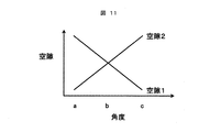
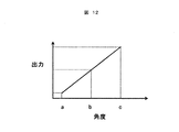
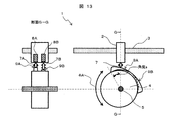
- (Angle c) It is a graph where the rotational position (angle a, angle b, angle c) of the disk-shaped object to be measured according to the present invention intersects with the relational characteristics of the gap 1 of the reference coil and the gap 2 of the sensing coil. It is a graph which shows the rotation position (angle a, angle b, angle c) of the disk-shaped to-be-measured object based on this invention, and the output 117 relationship. It is a block diagram which detected the rotation position of the disk-shaped to-be-measured object based on this invention, and made the reference surface and sensing surface which a reference coil and a sensing coil oppose make a rib shape.
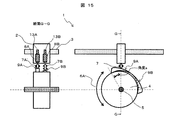
- the rotational position of the disk-shaped to-be-measured object which concerns on this invention, the reference surface and sensing surface which a reference coil and a sensing coil oppose are made into the shape of a rib, and the block diagram which equipped the reference coil and the sensing coil each with the core It is.
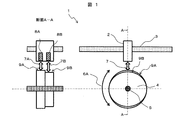
- FIG. 1 is a configuration diagram of a position detection apparatus 1 according to the present embodiment.
- FIG. 2 is a diagram illustrating a circuit 100 that detects a difference between the reference coil 8A and the sensing coil 8B of the position detection device 1 according to the present embodiment.
- the sensor 2 includes a reference surface 9A of the object to be measured 4, a reference coil 8A facing the sensing surface 9B, and a sensing coil 8B.
- the sensor 2 is fixed to the sensor mounting portion 3 and does not move. Further, the device under test 4 is supported by the device under test support 5 but rotates in the direction of the rotation direction 6A.
- the gap 7A between the reference surface 9A of the object to be measured 4 and the sensor 2 is constant even if the object to be measured 4 rotates in the rotational direction 6A because the reference surface 9A is an outer peripheral surface of a perfect circle.
- the gap 7B between the sensing surface 9B of the object to be measured 4 and the sensor 2 changes when the object to be measured 4 rotates in the rotation direction 6A because the sensing surface 9B is an outer periphery of the ellipse.
- the gaps 7A and 7B between the reference surface 9A, the sensing surface 9B, and the sensor 2 gradually increase from the same gap according to the angular position of the DUT 4. It changes into a gap with a difference.
- the reference coil 8A and the sensing coil 8B are configured as a bridge circuit 6 by a resistor 104A, a resistor 104B, and a reference-sensing coil balance adjustment volume 105.
- the bridge circuit 6 receives an AC voltage from the transmitter 101 located upstream.
- the inductances of the reference coil 8A and the sensing coil 8B change due to the gaps 7A and 7B between the measured object 4 and the impedance, respectively.
- An intermediate voltage between the impedance of the reference coil 8A and the impedance of the sensing coil 8B, and the combined voltage of the resistors 104A and 104B and the reference-sensing coil balance adjustment volume is input to the operational amplifier 107 of the differential amplifier circuit 108. Detect differences.
- the output of the operational amplifier 108 is input to the operational amplifier 109 of the detection circuit 111 that receives and detects the synchronization signal 110 from the transmitter 101.
- the output of the operational amplifier 109 is input to the operational amplifier 115 of the offset circuit 116 that offsets the output 117 together with the voltage obtained by dividing the reference voltage 112 by the resistor 113 and the offset adjustment volume.
- the output of the operational amplifier 107 is adjusted to 0 by the reference-sensing coil balance adjustment volume 105 at an arbitrary position of the DUT 4, and the reference coil 8 A and the sensing coil 8 B are adjusted. Individual variation can be canceled. Further, the output 117 can be adjusted by adjusting the offset adjustment volume 114 of the offset circuit 116 and the frequency adjustment volume 102 and the gain adjustment volume 103 of the transmitter 101.
- the sensor 2 detects the relative difference between the reference surface 9 ⁇ / b> A and the sensing surface 9 ⁇ / b> B and outputs an output 117 by adopting the configuration of the position detection device 1 of FIG. 1 and the circuit 100 of FIG. 2. For this reason, even if the gap 7 between the sensor 2 and the absolute position changes due to the positional deviation between the measured object support 5 and the measured object 4, the output 117 is hardly affected. Similarly, even if the gap 7 between the sensor 2 and the DUT 4 changes due to a temperature change, the output 117 is hardly affected. Furthermore, since the difference is detected even when the impedance characteristics of the reference coil 8A and the sensing coil 8B change due to temperature change, the output 117 is not easily affected.
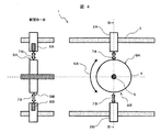
- FIG. 4 shows an example in which the reference coil 8A and the sensing coil 8B are arranged in sensors 2A and 2B, respectively.
- the sensor 2A side of the DUT 4 is a perfect circle as a reference surface 9A, and the sensor 2B side is an ellipse as a sensing surface 9B. The same effect as in the first embodiment can be obtained.
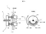
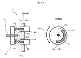
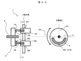
- FIG. 5 is an example in which the change in the gap between the sensor 2 and the object to be measured 4 is provided not in the radial direction of the object to be measured but in the rotation axis direction, and the sensing surface rotates in the rotation direction 6A of the object to be measured 4.
- the air gap 7B is changed by continuously changing the sensing surface (low) 9B-1, the sensing surface (middle) 9B-2, and the sensing surface (high) 9B-3 according to the time position. .
- the gap 7B changes.
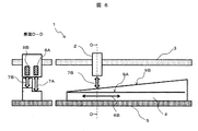
- FIG. 6 shows a configuration in which the position detection direction is changed from the rotation direction to the linear direction, and the DUT 4 moves in the movement direction 6B, and the sensor 2 detects the position.
- the same effect as in the first embodiment can be obtained.
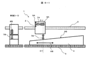
- FIG. 6A is a configuration in which the detection direction of the position is a linear direction as in FIG. 6, but by arranging the reference surface 9A in the sensor 2 instead of on the DUT 4, the gap 7A is fixed. An air gap is maintained, and only the sensing surface 9B is disposed on the DUT 4.
- the gap 7B changes in accordance with the amount of movement of the DUT 4 in the moving direction 6B. That is, when the DUT 4 moves in the moving direction 6B, the gaps 7A and 7B between the reference surface 9A, the sensing surface 9B, and the sensor 2 gradually increase from the same gap depending on the position of the DUT 4. It changes to a gap with a difference. In this configuration, the same effect as in the first embodiment can be obtained.
- the DUT 4 includes a cylindrical cylindrical portion 4A and a conical cone portion 4B, and the cylindrical portion 4A of the DUT 4 passes through the hole 5A of the DUT support portion 5.
- positioning form is shown.
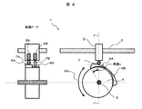
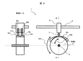
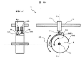
- FIG. 11 is a graph showing the relationship between the angle of the device under test 4 and the gap between the device under test 4 and the sensor 2.
- the air gap 1 indicates the air gap between the sensor 2 and the reference surface 9A
- the air gap 2 indicates the air gap between the sensor 2 and the sensing surface 9B.
- the sensitivity according to the rotation angle can be increased by setting the characteristic that the gap 1 and the gap 2 intersect. Further, by adjusting the reference-sensing coil balance adjustment volume based on the position of the angle b, the reference surface 9A and the sensing surface 9B are the same, that is, the air gap 1 and the air gap 2 are the same, and the object 4 to be measured is located at the angle b position. When the is located, the robustness against the change of the gap due to the positional deviation or the temperature change becomes high.
- the reference surface 9A and the sensing surface 9B are arranged in a rib shape as shown in FIG. 13 to improve the detection performance of the reference coil 9A and the sensing coil 9B, or the reference surface 9A and the sensing surface as shown in FIG. 9B may be separated by an insulating material 11 that is a magnetic material to improve the detection property, or the reference coil 8A and the sensing coil 8B may have different sensitivity configurations by changing the material of the reference surface 9A and the material of the sensing surface 9B. good.
- the cores 13A and 13B may be provided in the reference coil 8A and the sensing coil 8B, respectively, to improve the sensitivity.
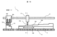
- FIG. 16 shows a configuration in which the position detection direction is a linear direction, the reference surface 9B is configured in a step shape, and the sensor 2 detects the position. In this configuration, the same effect as in the first embodiment can be obtained.
- this invention is not limited to each above-mentioned Example, Various modifications are included.
- the above-described embodiments have been described in detail for easy understanding of the present invention, and are not necessarily limited to those having all the configurations.
- a part of the configuration of one embodiment or modification can be replaced with the configuration of another embodiment or modification, and the configuration of another embodiment or modification can be replaced with the configuration of one embodiment or modification.
- SYMBOLS 1 Position detection apparatus, 2 ... Sensor, 3 ... Sensor mounting part, 4 ... Measured object, 4A ... Measured object cylindrical part, 4B ... Measured object cone part, 5 ... Measured object support part, 5A Measured object Support part hole, 6A ... rotational direction, 6B ... moving direction, 7 ... air gap, 7A ... air gap 1, 7B ... air gap 2, 8A ... reference coil, 8B ... sensing coil, 9A ... reference surface, 9B ... sensing surface, 9B -1 ... Sensing surface (low), 9B-2 ... Sensing surface (middle), 9B-3 ... Sensing surface (high), 10 ... Shield, 11A ...
- Angle a, 11B ... Angle b, 11C ... Angle c, 12 Insulating material, 13A ... core, 13B ... core, 100 ... detection circuit, 101 ... transmitter, 102 ... frequency adjustment volume, 103 ... gain adjustment volume, 104A ... resistance 1, 104B ... resistance 2, 105 ... reference-sensing coil balance Adjustment button 106... Bridge circuit 107 107 Operational amplifier 1 108 Differential amplification circuit 109 Operational amplifier 2 110 Synchronization signal 111 Detection circuit 112 Reference voltage 113 Resistance 114 Offset adjustment volume 115 ... Operational amplifier 3, 116 ... Offset circuit, 117 ... Output
Landscapes
- Engineering & Computer Science (AREA)
- Physics & Mathematics (AREA)
- General Physics & Mathematics (AREA)
- Chemical & Material Sciences (AREA)
- Combustion & Propulsion (AREA)
- Mechanical Engineering (AREA)
- General Engineering & Computer Science (AREA)
- Transmission And Conversion Of Sensor Element Output (AREA)
- Measurement Of Length, Angles, Or The Like Using Electric Or Magnetic Means (AREA)
Abstract
Description
図1乃至図2を用いて、本実施例に係る位置検出装置の構成について説明する。図1は、本実施例に係る位置検出装置1の構成図である。図2は、本実施例に係る位置検出装置1の参照コイル8Aとセンシングコイル8Bとの差分を検出する回路100を示す図である。
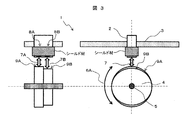
図3に示すように、図1の位置検出装置1の参照コイル8A、センシングコイル8Bを周囲を覆うようにシールド10を配置する事により、被測定物4に以外の方向からの外乱の影響を避ける事が可能である。シールドの材質は、軟磁性材で構成すると磁化の影響を受けにくくなる。
図4は、参照コイル8Aとセンシングコイル8Bをそれぞれセンサ2A、センサ2Bと別々のセンサに配した例である。被測定物4のセンサ2A側を真円として参照面9Aとし、センサ2B側をだ円としてセンシング面9Bとした構成であり、実施の形態1と同様の効果を得られる。
図5は、センサ2と被測定物4との空隙の変化を被測定物の半径方向ではなく、回転軸方向に設けた例であり、センシング面が被測定物4の回転方向6Aに回転した時の位置に応じて、センシング面(低)9B-1、センシング面(中)9B-2、センシング面(高)9B-3と連続して変化させることにより、空隙7Bを変化させるものである。図5-1、図5-2、図5-3のように被測定物4が回転した時に、空隙7Bが変化する。
図6は、位置の検出方向を回転方向から直線方向にした構成であり、移動方向6Bに被測定物4が移動し、センサ2がその位置を検出するものである。本構成においても実施の形態1同様の効果が得られる。
図6-1は、図6と同様位置の検出方向を直線方向にした構成であるが、参照面9Aを被測定物4上ではなく、センサ2内に配する事により、空隙7Aは一定の空隙を保持し、被測定物4にはセンシング面9Bのみ配する。被測定物4の移動方向6Bへの移動量に応じて空隙7Bが変化する構成となっている。つまり、被測定物4が移動方向6Bに移動した場合、上記の参照面9Aとセンシング面9Bとセンサ2との空隙7A、7Bは、被測定物4の位置に応じて同一の空隙から徐々に差のある空隙に変化する。本構成においても実施の形態1同様の効果が得られる。尚、参照面9Aをセンサ取付部3の一部を利用して構成しても良い。
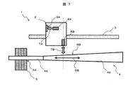
また、図7は、被測定物4は円筒状の円筒部4Aと円錐状の円錐部4Bからなり、被測定物支持部5の穴5Aを被測定物4の円筒部4Aが貫通するように配置された形態を示す。被測定物4を円筒や円錐状に形成することにより、被測定物4が移動方向6Bと垂直な面内で回転しても、参照コイル8Bと参照面9Bとの空隙7Bは変化せず、参照面9Aをセンサ2内に配する事により、被測定物4が回転しても位置検出が可能な構成となっている。尚、参照面9Aをセンサ取付部3の一部を利用した構成としても良い。
図8、9、10は、参照面9Aの一端からの角度a、角度b、角度cの位置に被測定物4がある図を示している。また、図11は被測定物4の角度と被測定物4とセンサ2との空隙の関係を示したグラフである。空隙1はセンサ2と参照面9A、空隙2はセンサ2とセンシング面9Bとの空隙を示す。
図16は、位置の検出方向を直線方向にした構成であり、参照面9Bを階段状に構成し、センサ2がその位置を検出するものである。本構成においても実施の形態1同様の効果が得られる。
ド、11A…角度a、11B…角度b、11C…角度c、12…絶縁材、13A…コア、13B…コア、100…検出回路、101…発信機、102…周波数調整ボリューム、103…ゲイン調整ボリューム、104A…抵抗1、104B…抵抗2、105…参照-センシングコイルバランス調整ボリューム、106…ブリッジ回路、107…オペアンプ1、108…差動増幅回路、109…オペアンプ2、110…同期信号、111…検波回路、112…基準電圧、113…抵抗、114…オフセット調整ボリューム、115…オペアンプ3、116…オフセット回路、117…出力
Claims (14)
- 被測定物に所定の空隙をもって取り付けられる位置検出装置であって、
前記被測定物は前記所定の空隙を変化させる機構を有し、
前記変化を内部に有するコイルのインダクタンスの変化として検出する位置検出装置。 - 請求項1に記載の位置検出装置であって、
前記機構は、連続的な変化をさせる機構であることを特徴とする位置検出装置。 - 請求項2に記載の位置検出装置であって、
前記機構は、階段状あるいは歯車形状あるいは凹凸形状からなることを特徴とする位置検出装置。 - 請求項2に記載の位置検出装置であって、
前記機構は、一つの被測定物に2種以上の空隙の変化をさせる機構であることを特徴とする位置検出装置。 - 請求項4に記載の位置検出装置であって、
前記機構の2種以上の空隙の変化を、センシングコイルと参照用コイルの2つのコイルで検出されるインダクタンスの変化の差分として検出することを特徴とする位置検出装置。 - 請求項5に記載の位置検出装置であって、
前記機構は、一方が円形状で他方が楕円形状であり、
前記円形状の機構変化を前記参照用コイルで検出し、前記楕円形状の機構変化を前記センシングコイルで検出することを特徴とする位置検出装置。 - 請求項4に記載の位置検出装置であって、
前記被測定物の移動方向と異なる方向に空隙を変化させる機構を設けたことを特徴とする位置検出装置。 - 請求項4に記載の位置検出装置であって、
前記機構は、複数のリブ形状からなることを特徴とする位置検出装置。 - 請求項4に記載の位置検出装置であって、
前記機構は、絶縁材を介して一方と他方の材料が異なることを特徴とする位置検出装置。 - 請求項1に記載の位置検出装置であって、
前記インダクタンスの変化を検出する面と異なる面をシールド材で覆うことを特徴とする位置検出装置。 - 請求項10に記載の位置検出装置であって、
前記シールド材は、軟磁性体からなることを特徴とする位置検出装置。 - 請求項5に記載の位置検出装置であって、
前記センシングコイルと前記参照用コイルとを一体にしたことを特徴とする位置検出装置。 - 請求項5に記載の位置検出装置であって、
前記参照用コイルは、前記被測定物とは異なる箇所の空隙を検出し、
前記センシングコイルは、前記被測定物の空隙の変化を検出することを特徴とする位置検出装置。 - 請求項5に記載の位置検出装置であって、
前記空隙の変化の検出の出力特性は、前記参照用コイルと前記センシングコイルとで交差する特性を有することを特徴とする位置検出装置。
Priority Applications (4)
| Application Number | Priority Date | Filing Date | Title |
|---|---|---|---|
| CN201680012151.6A CN107407578A (zh) | 2015-03-05 | 2016-02-26 | 位置检测装置 |
| US15/554,698 US20180080801A1 (en) | 2015-03-05 | 2016-02-26 | Position detection device |
| JP2017503450A JPWO2016140149A1 (ja) | 2015-03-05 | 2016-02-26 | 位置検出装置 |
| EP16758843.3A EP3267157A4 (en) | 2015-03-05 | 2016-02-26 | Position detection device |
Applications Claiming Priority (2)
| Application Number | Priority Date | Filing Date | Title |
|---|---|---|---|
| JP2015043102 | 2015-03-05 | ||
| JP2015-043102 | 2015-03-05 |
Publications (1)
| Publication Number | Publication Date |
|---|---|
| WO2016140149A1 true WO2016140149A1 (ja) | 2016-09-09 |
Family
ID=56848923
Family Applications (1)
| Application Number | Title | Priority Date | Filing Date |
|---|---|---|---|
| PCT/JP2016/055739 Ceased WO2016140149A1 (ja) | 2015-03-05 | 2016-02-26 | 位置検出装置 |
Country Status (5)
| Country | Link |
|---|---|
| US (1) | US20180080801A1 (ja) |
| EP (1) | EP3267157A4 (ja) |
| JP (1) | JPWO2016140149A1 (ja) |
| CN (1) | CN107407578A (ja) |
| WO (1) | WO2016140149A1 (ja) |
Cited By (4)
| Publication number | Priority date | Publication date | Assignee | Title |
|---|---|---|---|---|
| WO2017149975A1 (ja) * | 2016-02-29 | 2017-09-08 | 日立オートモティブシステムズ株式会社 | 位置検出装置 |
| JP2018096729A (ja) * | 2016-12-09 | 2018-06-21 | 日立オートモティブシステムズ株式会社 | 位置検出装置のセンサコイルユニット |
| JP2018155769A (ja) * | 2018-05-24 | 2018-10-04 | 日立金属株式会社 | ターボチャージャ |
| US20190264764A1 (en) * | 2016-08-02 | 2019-08-29 | Trw Automotive U.S. Llc | Brake pad wear sensor |
Families Citing this family (4)
| Publication number | Priority date | Publication date | Assignee | Title |
|---|---|---|---|---|
| JP6926502B2 (ja) * | 2017-02-10 | 2021-08-25 | 日立金属株式会社 | ターボ用回転センサ及びターボチャージャ |
| DE102019122360B4 (de) * | 2018-08-22 | 2024-02-01 | Tdk Corporation | Positionserfassungssystem |
| US11204258B2 (en) * | 2018-09-14 | 2021-12-21 | Samsung Electro-Mechanics Co., Ltd. | Apparatus for sensing rotating device |
| CN110307789B (zh) * | 2019-07-19 | 2021-09-07 | 哈尔滨工业大学 | 一种基于磁悬浮的浮子周向角位移可控装置 |
Citations (4)
| Publication number | Priority date | Publication date | Assignee | Title |
|---|---|---|---|---|
| JP2001004728A (ja) * | 1999-09-02 | 2001-01-12 | Micro Magune Kk | 磁気検出装置 |
| JP2002162252A (ja) * | 2000-09-18 | 2002-06-07 | Mitsubishi Electric Corp | 回転位置検出装置 |
| JP2007033100A (ja) * | 2005-07-25 | 2007-02-08 | Pulstec Industrial Co Ltd | 光学式位置検出装置 |
| WO2015165456A1 (de) * | 2014-04-30 | 2015-11-05 | Schaeffler Technologies AG & Co. KG | Verfahren zur erkennung einer rotorlage eines elektromotors, ein target zur bestimmung der rotorlage des elektromotors und ein elektromotor |
Family Cites Families (15)
| Publication number | Priority date | Publication date | Assignee | Title |
|---|---|---|---|---|
| US3356896A (en) * | 1964-12-16 | 1967-12-05 | Motorola Inc | Electronic device |
| US3465238A (en) * | 1967-10-02 | 1969-09-02 | Jacob Marlow | Position and velocity detecting apparatus |
| GB2131178B (en) * | 1982-11-30 | 1986-05-21 | Peutec Limited | Piston position transducer |
| JPS6017364A (ja) * | 1983-07-11 | 1985-01-29 | Fanuc Ltd | 電動機速度検出方式 |
| US4752732A (en) * | 1985-03-14 | 1988-06-21 | Baker-Hughes | Angular displacement sensor |
| DE60007202T2 (de) * | 1999-03-15 | 2004-11-04 | Goto, Atsutoshi, Fuchu | Induktiver Stellungsdetektor |
| US6305234B1 (en) * | 2000-01-27 | 2001-10-23 | Edward L. Thies | Absolute encoder |
| JP2004012308A (ja) * | 2002-06-07 | 2004-01-15 | Smc Corp | コイルを利用した位置測定装置、フロート式流量計および位置測定方法 |
| JP4206713B2 (ja) * | 2002-09-05 | 2009-01-14 | 株式会社デンソー | 指示計器 |
| DE102005051536A1 (de) * | 2005-04-27 | 2006-11-09 | Micro-Epsilon Messtechnik Gmbh & Co Kg | Berührungslos arbeitender Wirbelstromsensor und Verfahren zur Detektion von Messobjekten |
| DE102005021300B4 (de) * | 2005-05-09 | 2007-08-16 | Vs Sensorik Gmbh | Drehgeber |
| FR2937126B1 (fr) * | 2008-10-10 | 2010-12-31 | Continental Automotive France | Dispositif de mesure par effet hall |
| JP5133199B2 (ja) * | 2008-10-28 | 2013-01-30 | 株式会社ミツトヨ | 誘導検出型ロータリーエンコーダ |
| DE102012222202A1 (de) * | 2012-12-04 | 2014-06-05 | Robert Bosch Gmbh | Verfahren zur Überwachung einer Rotation eines Verdichterrades |
| DE102013207621B4 (de) * | 2013-04-26 | 2015-04-09 | Schaeffler Technologies AG & Co. KG | Winkelmessung, insbesondere berührungslos, mit Einzelsensoren |
-
2016
- 2016-02-26 US US15/554,698 patent/US20180080801A1/en not_active Abandoned
- 2016-02-26 EP EP16758843.3A patent/EP3267157A4/en not_active Withdrawn
- 2016-02-26 CN CN201680012151.6A patent/CN107407578A/zh active Pending
- 2016-02-26 WO PCT/JP2016/055739 patent/WO2016140149A1/ja not_active Ceased
- 2016-02-26 JP JP2017503450A patent/JPWO2016140149A1/ja active Pending
Patent Citations (4)
| Publication number | Priority date | Publication date | Assignee | Title |
|---|---|---|---|---|
| JP2001004728A (ja) * | 1999-09-02 | 2001-01-12 | Micro Magune Kk | 磁気検出装置 |
| JP2002162252A (ja) * | 2000-09-18 | 2002-06-07 | Mitsubishi Electric Corp | 回転位置検出装置 |
| JP2007033100A (ja) * | 2005-07-25 | 2007-02-08 | Pulstec Industrial Co Ltd | 光学式位置検出装置 |
| WO2015165456A1 (de) * | 2014-04-30 | 2015-11-05 | Schaeffler Technologies AG & Co. KG | Verfahren zur erkennung einer rotorlage eines elektromotors, ein target zur bestimmung der rotorlage des elektromotors und ein elektromotor |
Non-Patent Citations (1)
| Title |
|---|
| See also references of EP3267157A4 * |
Cited By (5)
| Publication number | Priority date | Publication date | Assignee | Title |
|---|---|---|---|---|
| WO2017149975A1 (ja) * | 2016-02-29 | 2017-09-08 | 日立オートモティブシステムズ株式会社 | 位置検出装置 |
| JPWO2017149975A1 (ja) * | 2016-02-29 | 2018-10-18 | 日立オートモティブシステムズ株式会社 | 位置検出装置 |
| US20190264764A1 (en) * | 2016-08-02 | 2019-08-29 | Trw Automotive U.S. Llc | Brake pad wear sensor |
| JP2018096729A (ja) * | 2016-12-09 | 2018-06-21 | 日立オートモティブシステムズ株式会社 | 位置検出装置のセンサコイルユニット |
| JP2018155769A (ja) * | 2018-05-24 | 2018-10-04 | 日立金属株式会社 | ターボチャージャ |
Also Published As
| Publication number | Publication date |
|---|---|
| EP3267157A1 (en) | 2018-01-10 |
| JPWO2016140149A1 (ja) | 2017-06-22 |
| CN107407578A (zh) | 2017-11-28 |
| US20180080801A1 (en) | 2018-03-22 |
| EP3267157A4 (en) | 2018-10-17 |
Similar Documents
| Publication | Publication Date | Title |
|---|---|---|
| JPWO2016140149A1 (ja) | 位置検出装置 | |
| US9207100B2 (en) | Magnetic position sensor with field direction measurement and flux collector | |
| US11143524B2 (en) | Displacement sensor | |
| US10330498B2 (en) | Sensor arrangement for the contactless sensing of angles of rotation on a rotating part | |
| US10732009B2 (en) | Angle sensing in an off-axis configuration | |
| JP5613839B2 (ja) | 移動する物体の絶対的な位置特定のための方法及び装置 | |
| CN101903749B (zh) | 角位置测量设备 | |
| US6323641B1 (en) | Non-contacting position sensor with helical flux linkage | |
| CN110546463B (zh) | 用于确定旋转构件的角位置的方法 | |
| US20170115134A1 (en) | Angle Sensor | |
| KR102677085B1 (ko) | 인코더 | |
| JP2020112579A (ja) | 回転検出装置及びその製造方法 | |
| US20190101416A1 (en) | Rotation detection device | |
| JP2007198843A (ja) | 磁気検出装置 | |
| JPH03506071A (ja) | 回転角検出測定装置 | |
| JP4521808B2 (ja) | エンコーダ | |
| WO2011012843A1 (en) | Proximity sensor | |
| JP6882530B2 (ja) | センサ装置 | |
| EP3896399A1 (en) | Sensor device and sensor assembly for measuring the rotational position of an element | |
| JP5959686B1 (ja) | 磁気検出装置 | |
| JP6695962B2 (ja) | 位置検出装置 | |
| CN111630350A (zh) | 旋转角度检测装置 | |
| JP6041959B1 (ja) | 磁気検出装置 | |
| US20200149926A1 (en) | Encoder With Toothed Structure and Apparatus Having the Same | |
| RU2398241C1 (ru) | Способ определения скорости движения |
Legal Events
| Date | Code | Title | Description |
|---|---|---|---|
| 121 | Ep: the epo has been informed by wipo that ep was designated in this application |
Ref document number: 16758843 Country of ref document: EP Kind code of ref document: A1 |
|
| ENP | Entry into the national phase |
Ref document number: 2017503450 Country of ref document: JP Kind code of ref document: A |
|
| WWE | Wipo information: entry into national phase |
Ref document number: 15554698 Country of ref document: US |
|
| REEP | Request for entry into the european phase |
Ref document number: 2016758843 Country of ref document: EP |
|
| NENP | Non-entry into the national phase |
Ref country code: DE |