WO2016143303A1 - 電動自転車 - Google Patents
電動自転車 Download PDFInfo
- Publication number
- WO2016143303A1 WO2016143303A1 PCT/JP2016/001130 JP2016001130W WO2016143303A1 WO 2016143303 A1 WO2016143303 A1 WO 2016143303A1 JP 2016001130 W JP2016001130 W JP 2016001130W WO 2016143303 A1 WO2016143303 A1 WO 2016143303A1
- Authority
- WO
- WIPO (PCT)
- Prior art keywords
- motor
- driving force
- gear
- electric bicycle
- force
- Prior art date
- Legal status (The legal status is an assumption and is not a legal conclusion. Google has not performed a legal analysis and makes no representation as to the accuracy of the status listed.)
- Ceased
Links
Images


Classifications
-
- B—PERFORMING OPERATIONS; TRANSPORTING
- B62—LAND VEHICLES FOR TRAVELLING OTHERWISE THAN ON RAILS
- B62M—RIDER PROPULSION OF WHEELED VEHICLES OR SLEDGES; POWERED PROPULSION OF SLEDGES OR SINGLE-TRACK CYCLES; TRANSMISSIONS SPECIALLY ADAPTED FOR SUCH VEHICLES
- B62M6/00—Rider propulsion of wheeled vehicles with additional source of power, e.g. combustion engine or electric motor
- B62M6/40—Rider propelled cycles with auxiliary electric motor
- B62M6/55—Rider propelled cycles with auxiliary electric motor power-driven at crank shafts parts
-
- B—PERFORMING OPERATIONS; TRANSPORTING
- B62—LAND VEHICLES FOR TRAVELLING OTHERWISE THAN ON RAILS
- B62M—RIDER PROPULSION OF WHEELED VEHICLES OR SLEDGES; POWERED PROPULSION OF SLEDGES OR SINGLE-TRACK CYCLES; TRANSMISSIONS SPECIALLY ADAPTED FOR SUCH VEHICLES
- B62M11/00—Transmissions characterised by the use of interengaging toothed wheels or frictionally-engaging wheels
- B62M11/04—Transmissions characterised by the use of interengaging toothed wheels or frictionally-engaging wheels of changeable ratio
- B62M11/14—Transmissions characterised by the use of interengaging toothed wheels or frictionally-engaging wheels of changeable ratio with planetary gears
- B62M11/145—Transmissions characterised by the use of interengaging toothed wheels or frictionally-engaging wheels of changeable ratio with planetary gears built in, or adjacent to, the bottom bracket
Definitions
- the present invention relates to an electric bicycle that can travel by adding an auxiliary driving force generated by a motor to a human driving force generated by a pedaling force from a pedal, and more particularly, an electric bicycle having a continuously variable transmission function capable of continuously changing a gear ratio.
- the present invention relates to a bicycle transmission.
- Patent Documents 1 and 2 have been proposed as having a continuously variable transmission function capable of continuously changing a gear ratio.
- Patent Document 1 a pressing shell and a friction shell that contact each other and transmit force by friction, a friction ring, a double cone that rotates around a cone axis and contacts the friction shell and the friction ring, and this double A bicycle transmission having an adjustment sleeve for adjusting the position of the cone is disclosed. Then, by adjusting the position of the double cone by mechanically rotating the adjustment sleeve from the outside, the length of the contact point between the double cone and the friction shell from the axis of the cone axis (the rotation radius of the contact portion) and The length of the contact point between the double cone and the friction ring from the axial center of the cone shaft (rotation radius of the contact portion) is mechanically changed to continuously change the speed.
- Patent Document 2 has two motors and two planetary gear mechanisms, and human power (stepping force from the pedal) is applied to the first part of one planetary gear mechanism (the planetary gear carrier in the embodiment).
- the third part of each planetary gear mechanism annular internal gear of the planetary gear in the embodiment
- rotating the second part of each planetary gear mechanism in the embodiment, the sun gear of the planetary gear
- a bicycle transmission system that outputs from is disclosed.
- JP 2013-249060 A Japanese Patent No. 5613899
- the bicycle transmission disclosed in Patent Document 1 has a structure in which a force is transmitted by a frictional force such as a friction shell or a friction ring during operation, and a lot of heat is generated by the frictional force, resulting in a lot of energy loss. Therefore, there is a risk that the power transmission efficiency is poor and the battery usage efficiency is low. In addition, since the gear ratio is changed using a double cone, the power transmission efficiency is poor and the battery usage efficiency may be reduced.
- an input position for example, a carrier that is a first component
- a position for example, a position where an auxiliary driving force from a motor is input
- the force output range may not be increased.
- the present invention provides an electric bicycle that has good power transmission efficiency and can increase the power output range.
- the present invention is an electric bicycle having a drive unit having a motor and capable of traveling by adding an auxiliary drive force generated by the motor to a human-powered drive force generated by a pedaling force from a pedal. Further, a crankshaft to which a manpower driving force from the pedal is transmitted, and a planetary gear mechanism having a planetary carrier that rotatably supports the planetary gear, a sun gear, and an internal gear are provided. Further, the first motor and the second motor are provided as motors, and the human power driving force and the auxiliary driving from the first motor are added to the first component which is one of the planetary carrier, the sun gear and the internal gear in the planetary gear mechanism. The resultant force combined with the force is transmitted.
- the auxiliary driving force from the second motor is transmitted to a second part different from the first part by any one of the planet carrier, the sun gear, and the internal gear in the planetary gear mechanism. Further, by adjusting the rotation speed of the second motor, the first component and the third component different from the second component are steplessly shifted by any one of the planet carrier, the sun gear, and the internal gear in the planetary gear mechanism. And can be rotated.
- the structure is such that the auxiliary drive force of the first motor and the second motor is applied using a planetary gear mechanism rather than a structure that transmits the force by a frictional force. Can be maintained. Further, not only the human driving force is transmitted to the first component of the planetary gear mechanism, but the resultant force obtained by combining the human driving force and the auxiliary driving force from the first motor is transmitted.
- the output range of the force can be expanded as compared with a configuration in which the force is shifted and then combined with the auxiliary driving force, or a configuration in which the auxiliary driving force is shifted and then combined with the human power driving force.
- the present invention is characterized in that the second part is an internal gear.
- the second part is an internal gear.
- the second component is an internal gear in this way, it is preferable to provide a reverse rotation prevention mechanism that prevents the internal gear from rotating in the direction opposite to the rotational drive direction by the second motor.
- a reverse rotation prevention mechanism that prevents the internal gear from rotating in the direction opposite to the rotational drive direction by the second motor.
- a sun gear or a planet carrier may be used as the first part to which the resultant force obtained by combining the human driving force and the auxiliary driving force from the first motor is transmitted.
- the sun gear As the first part, the resultant force can be output in a relatively low rotational speed range as compared with the case where the planetary carrier is used as the first part.
- a planet carrier As the first component, a resultant force can be output in a relatively high rotational speed range.
- the second motor is configured not to be driven at the start of traveling but to be rotatable after the start of traveling.
- the present invention provides a planetary gear mechanism disposed inside the drive unit, the drive unit is disposed at an intermediate position between the front wheel and the rear wheel, and the sun gear and the internal gear of the planetary gear mechanism are cranked. It is preferable to arrange it coaxially with the shaft. Further, it is preferable that the driving force output wheel body coaxial with the crankshaft is rotated at a higher speed by rotating the second motor at a higher speed.
- the manpower driving force, the auxiliary driving force from the first motor, and the auxiliary driving force from the second motor are combined as an output resultant force through the planetary gear mechanism, and this output resultant force is It is configured to be transmitted to the rear wheel via a driving force output wheel body coaxial with the shaft and an endless driving force transmission body stretched over the driving force output wheel body.
- a driving force output wheel body coaxial with the shaft and an endless driving force transmission body stretched over the driving force output wheel body.
- an endless driving force transmission body a chain may be used, but a toothed belt may be used instead.
- FIG. 1 is an overall side view of an electric bicycle according to an embodiment of the present invention.
- FIG. 2 is a partially cutaway side view of the electric bicycle according to the embodiment of the present invention.
- FIG. 3 is a right side view of the drive unit of the electric bicycle according to the embodiment of the present invention.
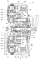
- FIG. 4 is a plan sectional view of the drive unit of the electric bicycle according to the first embodiment of the present invention.
- FIG. 5 is an enlarged plan sectional view of a main part of the drive unit of the electric bicycle according to the first embodiment of the present invention.
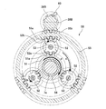
- FIG. 6 is a schematic right side view of the main part taken along line 6-6 of FIG. 5 in the drive unit in the state of starting the running of the electric bicycle according to the first embodiment of the present invention.
- FIG. 7 is a schematic right side view of the main part taken along line 6-6 of FIG. 5 in the drive unit in the running state of the electric bicycle according to the first embodiment of the present invention.
- FIG. 8 is a plan sectional view of the drive unit of the electric bicycle according to the second embodiment of the present invention.
- FIG. 9 is an enlarged plan cross-sectional view of the main part of the drive unit of the electric bicycle according to the second embodiment of the present invention.
- FIG. 10 is a schematic right side view of the main part as viewed from the line 10-10 in FIG. 9 in the drive unit in the state at the start of running of the electric bicycle according to the second embodiment of the present invention.
- FIG. 11 is a schematic right side view of the main part taken along line 10-10 in FIG. 9 in the drive unit in the running state of the electric bicycle according to the second embodiment of the present invention.
- the left-right direction and the front-rear direction refer to directions in which the electric bicycle 1 is mounted in the traveling direction.
- the configuration of the present invention is not limited to the configuration described below.
- the electric bicycle 1 includes a metal frame 2 including a head pipe 2a, a front fork 2b, a main pipe 2c, a standing pipe 2d, a chain stay 2e, a seat stay 2f, and the like.
- a front wheel 3 rotatably attached to the lower end of the front fork 2b
- a rear wheel 4 rotatably attached to the rear end of the chain stay 2e
- a handle 5 for changing the direction of the front wheel 3
- a crank 7 and a pedal 8 to which a human driving force including a pedaling force is applied are provided.
- the electric first motor 21A and the second motor 21B (see FIG. 4, etc.) as drive sources for generating the auxiliary driving force (assist force) and various types including the first motor 21A and the second motor 21B.
- the drive unit 20 provided with the control parts 24A and 24B (refer FIG. 4) etc. which perform electrical control is provided.
- the battery 12 is a secondary battery that supplies driving power to the first motor 21A and the second motor 21B, the handle 5 and the like, which can be operated by a passenger and the planetary gear mechanism 25 described later.
- a shift stage proximal operation unit 18 which can arbitrarily set the speed of the speed change function.
- a drive sprocket front sprocket, crank sprocket or front sprocket
- a drive sprocket is mounted as a driving force output wheel body that is mounted so as to rotate integrally and coaxially with the crankshaft 7a, and outputs a combined force of human driving force and auxiliary driving force.
- a rear sprocket also referred to as a rear gear
- a hub also referred to as a rear hub
- a chain 15 as an endless driving force transmission body wound endlessly in a state where it can rotate between the drive sprocket 13 and the rear sprocket 14, a chain cover 17 covering the chain 15 and the like from the side, and the like I have.
- the first motor 21A, the second motor 21B, and the two motors are provided in the drive unit 20.
- the battery 12 is an example of a capacitor, and a secondary battery is preferable.
- another example of the capacitor may be a capacitor.
- the crank 7 includes a crank arm 7b provided on each of the left and right sides, and a crank shaft 7a that connects the left and right crank arms 7b.
- a pedal 8 is rotatably attached to an end of the crank arm 7b.
- the drive unit 20 is located at an intermediate position between the front wheels 3 and the rear wheels 4 (more specifically, at the lower part of the intermediate position) such as substantially behind the crankshaft 7a. Is arranged. With such an arrangement, the drive unit 20 having a relatively large weight is arranged at the center in the front-rear direction of the electric bicycle 1, so that the front wheels 3 and the rear wheels 4 can be easily lifted and a step is formed on the travel path.
- the vehicle body (such as the frame 2) of the electric bicycle 1 is easy to handle, and the running stability is also good.
- FIG. 3 is a right side view of the drive unit 20, and FIG. 4 is a cross-sectional plan view of the drive unit 20.
- FIG. 4 is a cross-sectional plan view of the drive unit 20.
- the drive unit 20 has an outer shell portion or the like formed by a unit case 22 including a motor case 22a, a left case 22b, and a right case 22c, and the central portion of the drive unit 20 is connected to the crankshaft 7a. Penetrates from side to side. Also, a substantially cylindrical human power transmission body 28 to which the human power driving force from the crank shaft 7a is transmitted to the outer periphery of the crankshaft 7a, and an interlocking cylinder 23 to which the human power driving force from the human power transmission body 28 is transmitted, The human driving force from the interlocking cylinder 23 is transmitted through a one-way clutch (a one-way clutch for cutting auxiliary driving force) 30 and the like. In addition, a resultant force transmission body 29 that transmits a resultant force obtained by synthesizing the manpower driving force and the auxiliary driving force from the motor 21 to the drive sprocket 13 is provided.
- a resultant force transmission body 29 that transmits a resultant force obtained by synthesizing the manpower
- the resultant force (first resultant force) obtained by combining the human driving force and the auxiliary driving force from the first motor 21A is combined with the second motor 21B.
- a planetary gear mechanism 50 that is capable of continuously variable transmission while applying force is provided.
- a mechanism 25A is provided.
- the first reduction mechanism 25A transmits the auxiliary driving force of the first motor 21A to the sun gear 51 of the planetary gear mechanism 50 while reducing the speed.
- a plurality of reduction gears such as a low speed reduction gear 36B, a first intermediate shaft reduction gear 37B, a second intermediate shaft reduction gear 38B, and a locking tooth portion.
- a second reduction mechanism 25B having 39B and a motor shaft reduction gear 40B is disposed.
- the second reduction mechanism 25B transmits the auxiliary driving force of the second motor 21B to the internal gear 55 of the planetary gear mechanism 50 while reducing the speed.
- the planetary gear mechanism 50 also provides a function as an internal transmission (internal transmission).
- the first motor 21A is disposed on the rear left side in the unit case 22, and the electronic component for performing various electrical controls including the control of the first motor 21A is provided on the rear right side in the unit case 22.
- a control unit 24A having a substrate 24Aa, a storage unit for various information, and the like is provided.
- the second motor 21B is disposed on the left side of the front part in the unit case 22, and electronic components that perform various electrical controls including control of the second motor 21B are provided on the right side of the front part in the unit case 22.
- a control unit 24B having a control board 24Ba and a storage unit for various information is also provided.
- the control units 24A and 24B may be arranged in one place without being divided into two places.
- crankshaft 7a is rotatably arranged by bearings 26 and 27 in a state of passing through the central portion of the drive unit 20 to the left and right.
- a cylindrical human power transmission body 28 is fitted on the outer periphery of the left side portion of the crankshaft 7a via a serration portion (or spline portion) 7c so as to rotate integrally.
- a serration portion (or spline portion) 28b is also formed at a location corresponding to the serration portion (or spline portion) 7c of the crankshaft 7a on the inner periphery of the human power transmission body 28, so that the serration portion (or spline portion) of the crankshaft 7a is formed. ) Meshed with 7c.
- a magnetostriction generating portion 31b having magnetic anisotropy is formed on the outer peripheral surface of the human power transmission body 28.
- a coil 31a is disposed on the outer periphery via a certain gap (space), and a magnetostrictive torque sensor (human power detection unit) 31 is configured by the magnetostriction generating unit 31b and the coil 31a.
- the magnetostriction generator 31 b is formed in a spiral shape that forms, for example, +45 degrees and ⁇ 45 degrees with respect to the axial direction of the human power transmission body 28.
- the magnetostriction generating portion 31b on the surface of the manpower transmitting body 28 is distorted to generate an increase portion and a decrease portion of permeability. For this reason, the magnitude of torque (manual driving force) can be detected by measuring the inductance difference of the coil 31a.
- the interlocking cylinder 23 is disposed at a position adjacent to the right side of the human power transmission body 28 on the outer periphery of the crankshaft 7a so as to be rotatable with respect to the crankshaft 7a.
- the serration part (or spline part) 28a formed on the left side of the interlocking cylinder 23 and the serration part (or spline part) 23a formed on the inner periphery of the interlocking cylinder 23 are fitted together to rotate integrally with the human power transmission body 28. To do.
- a serration portion (or spline portion) 23a formed on the inner periphery of the left end portion of the interlocking cylinder 23 is fitted to the serration portion (or spline portion) 28a of the human power transmission body 28 from the outside.
- the rotation detector 11 for detecting the rotation state is attached to the interlocking cylinder 23 and the human power transmission body 28 (the attachment location of the rotation detector 11 is the interlocking cylinder 23 and the human power). Any part of the transmission body 28 may be used, and it may be directly attached to the crankshaft 7a). Further, a rotation detector (not shown) is fixed to the unit case 22 so as to sandwich the rotation detector 11 with a minute gap from the left and right.
- the crankshaft 7a and the pedal are detected by detecting the rotation amount and the rotating direction of the interlocking cylinder 23 and the manpower transmitting body 28. The rotation amount and the rotation direction of 8 can be detected.
- a low speed reduction gear (a reduction gear of the reduction gear) provided in the first reduction mechanism 25A is provided on the outer periphery of the right side portion of the interlocking cylinder 23 via a one-way clutch (one-way clutch for cutting auxiliary driving force) 30.
- 36A is disposed. When the pedal 8 is moved forward by scrambling, the manual driving force transmitted to the interlocking cylinder 23 is transmitted to the low speed reduction gear 36A of the first reduction mechanism 25A.
- the rotation shaft 21Aa and the rotor portion 21Ab of the first motor 21A are rotatably supported by motor bearings 32A and 33A. Further, the rotation shaft 21Aa of the first motor 21A protrudes rightward, and a motor shaft reduction gear 40A described later is formed on the outer periphery of the protrusion.
- the first reduction mechanism 25A includes an intermediate shaft 44A arranged in parallel with the crankshaft 7a, a low speed reduction gear 36A that is a reduction gear, and a first intermediate shaft reduction gear 37A. And a second intermediate shaft reduction gear 38A and a motor shaft reduction gear 40A. Then, the first reduction mechanism 25A combines the human driving force transmitted through the crankshaft 7a and the auxiliary driving force transmitted from the first motor 21A.
- the intermediate shaft 44A of the first speed reduction mechanism 25A is disposed in a state of being supported in a freely rotatable manner by bearings 34A and 35A in a posture parallel to the crankshaft 7a and extending in the left and right positions near the rear portion of the drive unit 20. .
- a one-way clutch 47A for cutting a human driving force, a large-diameter first intermediate shaft reduction gear 37A, a small-diameter second intermediate shaft reduction gear 38A, and the like are attached to the intermediate shaft 44A. When the one-way clutch 47A for cutting the human driving force is not disconnected, the first intermediate shaft reduction gear 37A and the second intermediate shaft reduction gear 38A rotate together with the intermediate shaft 44A.
- the motor shaft reduction gear 40A formed on the rotation shaft 21Aa of the first motor 21A has a small diameter and meshes with the large-diameter first intermediate shaft reduction gear 37A.
- the small-diameter second intermediate shaft reduction gear 38A meshes with a large-diameter low-speed reduction gear 36A that is rotatably disposed on the outer periphery of the crankshaft 7a.
- the manpower transmitted from the crankshaft 7a via the manpower transmitting body 28, the interlocking cylinder 23, and the one-way clutch 30 for cutting the auxiliary driving force is further transmitted to the low speed reduction gear 36A, thereby assisting driving.
- a resultant force obtained by combining the human driving force and the auxiliary driving force of the first motor 21 ⁇ / b> A is transmitted to the sun gear 51 of the planetary gear mechanism 50.
- the rotation shaft 21Ba and the rotor portion 21Bb of the second motor 21B are rotatably supported by motor bearings 32B and 33B. Further, the rotation shaft 21Ba of the second motor 21B protrudes to the right side, and a motor shaft reduction gear 40B described later is formed on the outer periphery of the protrusion.
- the second reduction mechanism 25B includes an intermediate shaft 44B disposed in parallel with the crankshaft 7a, a low speed reduction gear 36B as a reduction gear, and a first intermediate shaft reduction gear 37B. And a second intermediate shaft reduction gear 38B, a locking tooth portion 39B, and a motor shaft reduction gear 40B.
- the intermediate shaft 44B of the second speed reduction mechanism 25B extends in the left-right direction at a location near the front side of the drive unit 20 and is disposed in a state of being rotatably supported by the bearings 34B and 35B in a posture parallel to the crankshaft 7a. .
- a one-way clutch 47B for cutting a human driving force, a large-diameter first intermediate shaft reduction gear 37B, a small-diameter second intermediate shaft reduction gear 38B, and the like are attached to the intermediate shaft 44B.
- the one-way clutch 47B for cutting the human driving force is not disconnected, the first intermediate shaft reduction gear 37B and the second intermediate shaft reduction gear 38B rotate integrally with the intermediate shaft 44B.
- the motor shaft reduction gear 40B formed on the rotation shaft 21Ba of the second motor 21B has a small diameter and meshes with the large first intermediate shaft reduction gear 37B.
- the small-diameter second intermediate shaft reduction gear 38B meshes with the internal gear 55 of the planetary gear mechanism 50 from the outside.
- the torque of the auxiliary driving force from the second motor 21B is transmitted to the internal gear 55 of the planetary gear mechanism 50 in an amplified state.
- the planetary gear mechanism 50 of this embodiment is integrally formed on the outer periphery of the right small diameter portion 36bA in the low speed reduction gear 36A. Then, the sun gear (first component in this embodiment) 51 rotatably disposed on the outer periphery of the crankshaft 7a via the bearing 56 and the tooth portion 51a of the sun gear 51 are revolved by the small diameter tooth portion 52a.
- a plurality of (for example, three) planetary gears 52 that mesh with each other in a rotatable state, a planetary gear shaft 53 that rotatably supports the planetary gears 52, and a planet carrier 54 that rotatably supports the planetary gear shafts 53. Is provided.
- an internal gear (in this embodiment, the first gear in this embodiment) is rotatably supported coaxially with the crankshaft 7a via bearings 57 and 58, and the inner teeth 55a mesh with the large-diameter tooth portion 52b of the planetary gear 52 from the outer peripheral side. 2 parts) 55.
- the external gear 55b is formed on the outer periphery of the internal gear 55, and the external gear 55b of the internal gear 55 is meshed with the second intermediate shaft reduction gear 38B of the second reduction mechanism 25B. .
- a locking tooth portion 39B is further formed on the intermediate shaft 44B of the second reduction gear mechanism 25B, and the internal gear 55 is opposite to the sun gear 51 in the locking tooth portion 39B (counterclockwise in FIG. 6). ) (That is, the intermediate shaft 44B of the second speed reduction mechanism 25B is prevented from rotating in the clockwise direction in FIG. 6) and the tip of the claw portion of the one-way clutch (reverse rotation prevention mechanism) 60 is engaged. It is supposed to be removable.
- the right planet carrier 54 is integrally formed with the resultant force transmission body 29, and the output from the planet carrier 54 of the planetary gear mechanism 50 is transmitted to the resultant force transmission body 29. That is, the planetary gear mechanism 50 of this embodiment inputs the resultant force (first resultant force) between the human driving force and the auxiliary driving force transmitted from the first motor 21A from the sun gear 51 and transmits it from the second motor 21B. The resultant auxiliary driving force is input from the internal gear 55, and the resultant force (second resultant force) obtained by combining these is output from the planet carrier 54. Further, the internal gear 55 is rotated in the same direction as the sun gear 51 by the auxiliary driving force from the second motor 21B, so that the planet carrier (third component in this embodiment) 54 of the planetary gear mechanism 50 rotates. Increases speed.
- the first motor 21A is rotated according to the torque acting on the crankshaft 7a, and the auxiliary driving force from the first motor 21A is added to the human power driving force.
- a resultant force (first resultant force) obtained by combining the driving force and the auxiliary driving force of the first motor 21 ⁇ / b> A is transmitted to the sun gear 51 of the planetary gear mechanism 50.
- the sun gear 51 of the planetary gear mechanism 50 is rotated in the a direction (clockwise direction) when viewed from the right side, and the planetary gear 52 is rotated in the b direction (counterclockwise direction). Rotate to.
- the second motor 21B is not driven.
- the internal gear 55 attempts to rotate counterclockwise by receiving a force from the planetary gear 52.
- the one-way clutch (reverse rotation prevention mechanism) 60 is provided in the second reduction mechanism 25B, the internal gear 55 is prevented from rotating counterclockwise, and the internal gear 55 is fixed.
- the planetary carrier 54 rotates in the c direction (clockwise direction) at a relatively low rotational speed, and the resultant force (first resultant force) obtained by combining the human power driving force and the first motor 21A. Is output from the low-rotation resultant force transmission body 29 and the drive sprocket 13.
- the planetary carrier 54 rotates in the c direction (clockwise direction) at a relatively high rotational speed, and further increases to a resultant force (first resultant force) obtained by combining the human power driving force and the auxiliary driving force of the first motor 21A.
- the resultant force (second resultant force) obtained by combining the auxiliary driving forces of the two motors 21 ⁇ / b> B is output from the high-speed resultant force transmission body 29 and the drive sprocket 13.
- the gear position hand operating unit 18 is operated to instruct to shift to a higher speed side
- the second motor 21B is driven at a higher speed, and the second resultant force is a higher resultant force.
- the planetary carrier 54 is shifted to a higher rotation speed (high speed) and output steplessly while adding the auxiliary driving force of the second motor 21B ( High speed).
- the planetary carrier 54 as the third component in the planetary gear mechanism 50 can be rotated steplessly and output.
- the power transmission efficiency can be maintained well.
- the bicycle transmission as disclosed in Patent Document 1 has a structure that adjusts the position of the double cone by mechanically rotating the adjustment sleeve from the outside. Mechanically transmitting parts must be provided.
- the human driving force is transmitted to the sun gear 51 of the planetary gear mechanism 50 (in this embodiment, the first part of the planetary gear mechanism 50), but the human driving force and the first motor 21A The resultant combined force with the auxiliary driving force is transmitted. Therefore, the output range of the force can be expanded compared to the configuration in which the manual driving force is shifted and then combined with the auxiliary driving force, or the configuration in which the auxiliary driving force is shifted and then combined with the human driving force.
- the one-way clutch (reverse rotation prevention mechanism) 60 that prevents the internal gear 55 from rotating in the direction opposite to the rotational drive direction by the second motor 21B is provided, auxiliary drive force is added.
- the power corresponding to the human driving force is output to the rear wheel 4 without any trouble even if the first motor 21A and the second motor 21B are not energized. be able to.
- the sun gear 51 is used as the first component (first component of the planetary gear mechanism 50) to which the resultant force obtained by combining the human driving force and the auxiliary driving force from the first motor 21A is transmitted.
- the present invention is not limited to this, and the planetary carrier 74 may be the first component to which the resultant force obtained by combining the human driving force and the auxiliary driving force from the first motor 21A is transmitted.
- the first motor 21A, the second motor 21B, the first speed reduction mechanism 25A, the second speed reduction mechanism 25B having the same configuration as the first embodiment, A direction clutch (reverse rotation prevention mechanism) 61 and the like are provided.
- the right side portion of the low speed reduction gear 36A which is a reduction gear, to which a resultant force obtained by combining the human driving force and the auxiliary driving force from the first motor 21A is transmitted is a planetary gear.
- the planetary carrier 74 of the gear mechanism 70 is integrally formed.
- a resultant force transmission body 29 is integrally formed on the right side of the sun gear 71 of the planetary gear mechanism 70.
- the planetary gear mechanism 70 of this embodiment includes a sun gear 71 that is rotatably disposed on the outer periphery of the crankshaft 7a via a bearing 76, as shown in FIGS. And a plurality of (for example, three) planetary gears 72 that mesh with each other in a state where they can revolve and rotate with the small-diameter tooth portion 72a. Further, a planetary gear shaft 73 that rotatably supports the planetary gear 72 and a planet carrier (first component in this embodiment) 74 that rotatably supports the planetary gear shaft 73 are provided.
- an internal gear (in this embodiment, the first gear in this embodiment) is rotatably supported coaxially with the crankshaft 7a via bearings 77 and 78, and the inner teeth 75a mesh with the large-diameter tooth portion 72b of the planetary gear 72 from the outer peripheral side. 2 parts) 75.
- external teeth 75b are formed on the outer periphery of the internal gear 75, and the external teeth 75b of the internal gear 75 are meshed with the second intermediate shaft reduction gear 38B of the second reduction mechanism 25B.
- a locking tooth portion 39B is further formed on the intermediate shaft 44B of the second reduction mechanism 25B, and an internal gear 75 extends in the same direction as the planet carrier 74 (clockwise in FIG. 10).
- the tip of the claw portion of the one-way clutch (reverse rotation prevention mechanism) 61 that prevents the rotation (that is, prevents the intermediate shaft 44B of the second reduction mechanism 25B from rotating counterclockwise in FIG. 10) is engaged and disengaged. It is supposed to be free.
- the right side portion of the low speed reduction gear 36A which is a reduction gear, to which the resultant force obtained by combining the human driving force and the auxiliary driving force from the first motor 21A is transmitted is the planetary gear mechanism 70.
- the planetary carrier 74 is integrally formed.
- the resultant force transmission body 29 is integrally formed on the right side of the sun gear 71 of the planetary gear mechanism 70, and the output from the sun gear 71 of the planetary gear mechanism 70 is transmitted to the resultant force transmission body 29. That is, the planetary gear mechanism 70 of this embodiment uses a planetary carrier (first component in this embodiment) 74 as a resultant force (first resultant force) of the human driving force and the auxiliary driving force transmitted from the first motor 21A. Enter from.
- the auxiliary driving force transmitted from the second motor 21B is input from an internal gear (second component in this embodiment) 75. Then, the resultant force (second resultant force) obtained by combining these components is output from the sun gear 71. Further, the internal gear 75 is rotated in the direction opposite to the planet carrier 74 by the auxiliary driving force from the second motor 21B, whereby the rotational speed of the sun gear (the third component in this embodiment) 71 is increased.
- the first motor 21A when the electric bicycle 1 starts to travel, the first motor 21A is rotated according to the torque acting on the crankshaft 7a, and the auxiliary driving force from the first motor 21A is added to the human driving force.
- a resultant force (first resultant force) obtained by combining the human driving force and the auxiliary driving force of the first motor 21 ⁇ / b> A is transmitted to the planet carrier 74 of the planetary gear mechanism 70.
- the planet carrier 74 of the planetary gear mechanism 70 is rotated in the f direction (clockwise direction) when viewed from the right side.
- the sun gear 71 rotates in the h direction (clockwise direction) at a relatively high rotational speed, and further increases to a resultant force (first resultant force) obtained by combining the human power driving force and the auxiliary driving force of the first motor 21A.
- the resultant force (second resultant force) obtained by combining the auxiliary driving forces of the two motors 21 ⁇ / b> B is output from the high-speed resultant force transmission body 29 and the drive sprocket 13.
- the gear position operating unit 18 is operated to instruct to shift to a higher speed side
- the second motor 21B is driven at a higher speed and the second resultant force is transmitted at a higher speed.
- the rotation of the resultant force transmission body 29 and the driving sprocket 13 which are output units can be adjusted extremely finely and smoothly.
- the human driving force is transmitted to the planet carrier 74 (in this embodiment, the first part of the planetary gear mechanism 70) of the planetary gear mechanism 70, but the human driving force and the first motor 21A.
- the resultant combined force with the auxiliary driving force is transmitted. Therefore, the output range of the force can be expanded compared to the configuration in which the manual driving force is shifted and then combined with the auxiliary driving force, or the configuration in which the auxiliary driving force is shifted and then combined with the human driving force.
- the one-way clutch (reverse rotation prevention mechanism) 61 that prevents the internal gear 75 from rotating in the direction opposite to the rotation direction by the second motor 21B is provided. Therefore, when the auxiliary driving force is not applied, or when the remaining amount of the battery 12 is low, even if the first motor 21A and the second motor 21B are not energized, the force corresponding to the human driving force can be obtained without any trouble. It can output to the rear wheel 4 side.
- the sun gear 51 and the planet carrier 74 are the first parts of the planetary gear mechanisms 50 and 70 to which the resultant force obtained by combining the human driving force and the auxiliary driving force from the first motor 21A is transmitted.
- the present invention is not limited to this, and it is also possible to use an internal gear as the first component of the planetary gear mechanism to which a resultant force obtained by combining the human driving force and the auxiliary driving force from the first motor is transmitted.
- the case where the second parts of the planetary gear mechanisms 50 and 70 to which the auxiliary driving force from the second motor 21B is transmitted is the internal gears 55 and 75 has been described.
- the present invention is not limited to this, and it is also possible to use a sun gear or a planet carrier as the second part of the planetary gear mechanism to which the auxiliary driving force from the second motor is transmitted (in this case, however, A planetary carrier (when using a sun gear as the second part) or a sun gear (when using a planetary carrier as the second part) is used as the first part).
- a planetary carrier (when using a sun gear as the second part) or a sun gear (when using a planetary carrier as the second part) is used as the first part).
- the third component to which the output resultant force from the planetary gear mechanisms 50 and 70 is output is the planet carrier 54 or the planetary gear mechanism of the planetary gear mechanism 50.
- the case of 70 sun gears 71 has been described.
- the present invention is not limited to this, and it is also possible to use an internal gear as a third component that outputs the output resultant force from the planetary gear mechanism (that is rotated and rotated steplessly).
- an internal gear is used as the third component, a sun gear or a planet carrier is used as the first component or the second component.
- the present invention is not limited to this, and a toothed belt is used as the endless driving force transmission body, and the force from the driving gear corresponding to the driving sprocket is transmitted to the rear gear via the toothed belt. May be.
- the present invention is applicable to various electric bicycles that can travel by adding an auxiliary driving force generated by a motor to a human driving force generated by a pedaling force from a pedal.
Landscapes
- Engineering & Computer Science (AREA)
- Chemical & Material Sciences (AREA)
- Combustion & Propulsion (AREA)
- Transportation (AREA)
- Mechanical Engineering (AREA)
- Retarders (AREA)
- Structure Of Transmissions (AREA)
- Electric Propulsion And Braking For Vehicles (AREA)
Abstract
第1モータ(21A)と第2モータ(21B)とを有する駆動ユニット(20)と、遊星歯車(52)を回転自在に支持する遊星キャリア(54)と太陽歯車(51)と内歯車(55)とを有する遊星歯車機構(50)を備える。また、遊星歯車機構(50)における遊星キャリア(54)と太陽歯車(51)と内歯車(55)との何れかである第1部品に、人力駆動力と第1モータ(21A)からの補助駆動力とが合成された合力が伝達される。また、遊星歯車機構(50)における遊星キャリア(54)と太陽歯車(51)と内歯車(55)との何れかで第1部品とは異なる第2部品に、第2モータ(21B)からの補助駆動力が伝達される。
Description
本発明は、ペダルからの踏力による人力駆動力に、モータにより発生する補助駆動力を加えて走行可能である電動自転車、詳しくは、変速比を連続的に変更可能な無段変速機能を有する電動自転車の変速装置に関するものである。
バッテリなどの蓄電器から給電されるモータを有し、ペダルに加えられる踏力からなる人力駆動力をトルクセンサにより検出し、人力駆動力に対応したモータの補助駆動力(アシスト力)を加えることで、上り坂等でも楽に走行できる電動自転車は既に知られている。
この電動自転車において、変速比を連続的に変更可能な無段変速機能を有するものとして、例えば、特許文献1、2等に開示された構造が提案されている。
特許文献1には、互いに接触して摩擦により力が伝達される押圧シェルおよび摩擦シェルと、摩擦リングと、コーン軸を中心として回転し、摩擦シェルおよび摩擦リングに接触するダブルコーンと、このダブルコーンの位置を調整する調整スリーブと、を有する自転車変速機が開示されている。そして、調整スリーブを外部から機械的に回転させてダブルコーンの位置を調整することで、ダブルコーンと摩擦シェルとの接触点のコーン軸の軸心からの長さ(接触部の回転半径)と、ダブルコーンと摩擦リングとの接触点のコーン軸の軸心からの長さ(接触部の回転半径)とを機械的に変更させて、無段変速させている。
また、特許文献2には、2つのモータと2つの遊星歯車機構とを有し、一方の遊星歯車機構の第1部品(実施の形態では遊星歯車のキャリア)に人力(ペダルからの踏力)を入力させ、各遊星歯車機構の第2部品(実施の形態では遊星歯車の太陽歯車)をそれぞれモータで回転させながら、各遊星歯車機構の第3部品(実施の形態では遊星歯車の環状内歯車)から出力する自転車変速システムが開示されている。
しかしながら、特許文献1に開示されている自転車変速機では、作動時に摩擦シェルや摩擦リングなどの摩擦力により力を伝達する構造であり、摩擦力による多くの熱が発生して多くのエネルギーロスを伴うため、力の伝達効率が悪くて、バッテリの使用効率が低くなるおそれがある。また、ダブルコーンを用いて変速比を変更する構成なので、これによっても、力の伝達効率が悪くて、バッテリの使用効率が低くなるおそれがあった。
また、特許文献2に開示されている自転車変速システムでは、人力からの遊星歯車機構への入力箇所(例えば、第1部品であるキャリア)と、モータからの補助駆動力を入力する箇所(例えば、第2部品である太陽歯車)とが異なるため、力の出力範囲を大きくできなくなるおそれがある。
本発明は、力の伝達効率が良好で、かつ、力の出力範囲を大きくできる電動自転車を提供する。
本発明は、モータを有する駆動ユニットを有し、ペダルからの踏力による人力駆動力に、モータにより発生する補助駆動力を加えて走行可能である電動自転車である。また、ペダルからの人力駆動力が伝達されるクランク軸と、遊星歯車を回転自在に支持する遊星キャリアと太陽歯車と内歯車とを有する遊星歯車機構と、が備えられている。また、モータとして第1モータと第2モータとを有し、遊星歯車機構における遊星キャリアと太陽歯車と内歯車との何れかである第1部品に、人力駆動力と第1モータからの補助駆動力とが合成された合力が伝達される。また、遊星歯車機構における遊星キャリアと太陽歯車と内歯車との何れかで第1部品とは異なる第2部品に、第2モータからの補助駆動力が伝達される。さらに、第2モータの回転数を調整することで、遊星歯車機構における遊星キャリアと太陽歯車と内歯車との何れかで第1部品および第2部品とは異なる第3部品を無段階に変速させて回転可能に構成する。
この構成によれば、摩擦力により力を伝達する構造ではなく、遊星歯車機構を用いて、第1モータと第2モータとの補助駆動力を加える構成であるので、力の伝達効率を良好に維持することが可能となる。また、遊星歯車機構の第1部品に、人力駆動力だけが伝達されるのではなくて、人力駆動力と第1モータからの補助駆動力とが合成された合力が伝達されるので、人力駆動力を変速した後に補助駆動力と合成する構成や、補助駆動力を変速した後に人力駆動力と合成する構成の場合よりも、力の出力範囲を広げることができる。
また、本発明は第2部品が内歯車であることを特徴とする。この構成により、内歯車を大きな回転数で回転することによって、第2のモータの補助駆動力も加えながら、より大きな回転数に変速させて無段階に出力させることができる。
また、このように第2部品が内歯車である場合に、内歯車が第2モータによる回転駆動方向と逆方向に回転することを阻止する逆回転阻止機構を設けることが好ましい。この構成によれば、補助駆動力を付加しない時や、バッテリの残量が少なくなった場合などに、第1モータや第2モータに通電させないでも、支障なく人力駆動力に対応する力を後輪側に出力することができる。つまり、例えば、特許文献2などに開示されている構成の場合には、遊星歯車機構の1つの部品(特許文献2の実施の形態では遊星歯車のキャリア)に人力が入力され、他の部品(特許文献2の実施の形態では遊星歯車の太陽歯車)をモータで(補助駆動)回転させながら、他の部品から出力する構成である。そのため、特許文献2の構成では両方のモータとも通電しなければ、モータに接続された部品(例えば太陽歯車)が空転してしまい、人力も殆ど出力されなくなってしまう不具合があるが、本発明によればこのような不具合を生じることがない。
また、人力駆動力と第1モータからの補助駆動力とが合成された合力が伝達される第1部品としては、太陽歯車を用いてもよいし、遊星キャリアを用いてもよい。第1部品として太陽歯車を用いることで、第1部品として遊星キャリアを用いる場合と比較して、比較的低い回転数範囲で合力を出力することができる。また、第1部品として、遊星キャリアを用いることで、比較的高い回転数範囲で合力を出力することができる。
また、第2モータは、走行開始時には駆動されず、走行開始後に回転可能に構成されることが好ましい。
また、本発明は、遊星歯車機構を、駆動ユニットの内部に配設し、駆動ユニットを前輪と後輪との間の中間位置に配設し、遊星歯車機構の太陽歯車および内歯車を、クランク軸と同軸心で配設することが好ましい。また、第2モータをより高速で回転することにより、クランク軸と同軸心の駆動力出力輪体がより高速で回転するよう構成することが好ましい。
また、本発明は、遊星歯車機構を介して、人力駆動力と第1モータからの補助駆動力と第2モータからの補助駆動力とが出力用合力として合成され、この出力用合力が、クランク軸と同軸心の駆動力出力輪体と、この駆動力出力輪体に掛け渡された無端状駆動力伝達体とを介して、後輪に伝達されるよう構成されていることを特徴とする。なお、無端状駆動力伝達体としては、チェーンを用いてもよいが、これに代えて歯付きベルトを用いてもよい。
以下、本発明の実施の形態に係る電動自転車について図面に基づき説明する。なお、以下の説明における左右方向および前後方向とは、進行方向に向ってこの電動自転車1に搭乗した状態での方向を言う。但し、この発明の構成が以下で述べる構成に限定されるものではない。
(第1の実施の形態)
図1、図2は、本発明の第1の実施の形態に係る電動自転車1を示す。図1、図2などに示すように、この電動自転車1は、ヘッドパイプ2a、前フォーク2b、メインパイプ2c、立パイプ2d、チェーンステー2e、シートステー2fなどからなる金属製のフレーム2を備える。また、前フォーク2bの下端に回転自在に取り付けられた前輪3と、チェーンステー2eの後端に回転自在に取り付けられた後輪4と、前輪3の向きを変更するハンドル5と、サドル6と、踏力からなる人力駆動力がかけられるクランク7およびペダル8を備える。また、補助駆動力(アシスト力)を発生させる駆動源としての電動の第1モータ21A、第2モータ21B(図4など参照)およびこれらの第1モータ21A、第2モータ21Bを含めた各種の電気的制御を行う制御部24A、24B(図4参照)などが設けられた駆動ユニット20を備える。また、第1モータ21A、第2モータ21Bに駆動用の電力を供給する二次電池からなるバッテリ12と、ハンドル5などに取り付けられて、搭乗者などが操作可能で、後述する遊星歯車機構25の変速機能の速度を任意に設定可能とされた変速段手元操作部18を備える。また、ハンドル5などに取り付けられて、搭乗者などが操作可能で、この電動自転車1の電源の切り換えや走行モードなどを設定する手元設定部(図示せず)を備える。また、クランク軸7aと同軸心で一体的に回転するように取り付けられ、人力駆動力および補助駆動力が合わされた合力を出力する駆動力出力輪体としての駆動スプロケット(前スプロケット、クランクスプロケットや前ギヤとも称せられる)13と、後輪4のハブ(後ハブとも称する)9に取り付けられた後部輪体としての後スプロケット(後ギヤとも称せられることがある)14とを備える。さらに、駆動スプロケット13と後スプロケット14とにわたって回転可能な状態で無端状に巻回された無端状駆動力伝達体としてのチェーン15と、チェーン15などを側方から覆うチェーンカバー17と、などを備えている。前述したように、本発明の実施の形態に係る電動自転車1では、駆動ユニット20内に第1モータ21Aおよび第2モータ21B、2つのモータが設けられている。
図1、図2は、本発明の第1の実施の形態に係る電動自転車1を示す。図1、図2などに示すように、この電動自転車1は、ヘッドパイプ2a、前フォーク2b、メインパイプ2c、立パイプ2d、チェーンステー2e、シートステー2fなどからなる金属製のフレーム2を備える。また、前フォーク2bの下端に回転自在に取り付けられた前輪3と、チェーンステー2eの後端に回転自在に取り付けられた後輪4と、前輪3の向きを変更するハンドル5と、サドル6と、踏力からなる人力駆動力がかけられるクランク7およびペダル8を備える。また、補助駆動力(アシスト力)を発生させる駆動源としての電動の第1モータ21A、第2モータ21B(図4など参照)およびこれらの第1モータ21A、第2モータ21Bを含めた各種の電気的制御を行う制御部24A、24B(図4参照)などが設けられた駆動ユニット20を備える。また、第1モータ21A、第2モータ21Bに駆動用の電力を供給する二次電池からなるバッテリ12と、ハンドル5などに取り付けられて、搭乗者などが操作可能で、後述する遊星歯車機構25の変速機能の速度を任意に設定可能とされた変速段手元操作部18を備える。また、ハンドル5などに取り付けられて、搭乗者などが操作可能で、この電動自転車1の電源の切り換えや走行モードなどを設定する手元設定部(図示せず)を備える。また、クランク軸7aと同軸心で一体的に回転するように取り付けられ、人力駆動力および補助駆動力が合わされた合力を出力する駆動力出力輪体としての駆動スプロケット(前スプロケット、クランクスプロケットや前ギヤとも称せられる)13と、後輪4のハブ(後ハブとも称する)9に取り付けられた後部輪体としての後スプロケット(後ギヤとも称せられることがある)14とを備える。さらに、駆動スプロケット13と後スプロケット14とにわたって回転可能な状態で無端状に巻回された無端状駆動力伝達体としてのチェーン15と、チェーン15などを側方から覆うチェーンカバー17と、などを備えている。前述したように、本発明の実施の形態に係る電動自転車1では、駆動ユニット20内に第1モータ21Aおよび第2モータ21B、2つのモータが設けられている。
なお、バッテリ12は蓄電器の一例であり、二次電池が好適であるが、蓄電器の他の例としてはキャパシタなどであってもよい。なお、クランク7は、左右にそれぞれ設けられるクランクアーム7bと、左右のクランクアーム7b同士を連結するクランク軸7aとからなり、クランクアーム7bの端部にペダル8が回転自在に取り付けられている。
図1、図2に示すように、この電動自転車1では、駆動ユニット20が、クランク軸7aの略後方など、前輪3と後輪4との間の中間位置(より詳しくは中間位置の下部)に配置されている。そして、このような配置構成にすることで、重量が比較的大きい駆動ユニット20が、電動自転車1の前後方向中央に配置されるため、前輪3や後輪4を持ち上げ易くて、走行路に段差があっても容易に乗り越えることができるなど、電動自転車1の車体(フレーム2など)の取り回しがよく、また、走行安定性も良好とされている。
図3は駆動ユニット20の右側面図、図4は駆動ユニット20の平面横断面図である。
図3、図4に示すように、駆動ユニット20は、モータケース22a、左側ケース22b、右側ケース22cからなるユニットケース22により外殻部などが構成され、駆動ユニット20の中央部をクランク軸7aが左右に貫通している。また、クランク軸7aの外周に、クランク軸7aからの人力駆動力が伝達される略筒状の人力伝達体28と、人力伝達体28からの人力駆動力が伝達される連動筒体23と、連動筒体23からの人力駆動力が一方向クラッチ(補助駆動力切断用の一方向クラッチ)30などを介して伝達される。加えて、人力駆動力とモータ21からの補助駆動力とを合成した合力を駆動スプロケット13に伝達する合力伝達体29と、が配設されている。
また、ユニットケース22内の駆動ユニット20における前後方向中央部の右寄り箇所に、人力駆動力と第1モータ21Aからの補助駆動力とが合成された合力(第1合力)に第2モータ21Bの力を加えながら無段変速可能とされた遊星歯車機構50が設けられている。また、駆動ユニット20における後部寄り箇所には複数の減速用歯車である低速用減速歯車36A、第1中間軸減速歯車37A、第2中間軸減速歯車38Aおよびモータ軸減速歯車40Aを有する第1減速機構25Aが配設されている。後述するように、この第1減速機構25Aは、第1モータ21Aの補助駆動力を減速しながら遊星歯車機構50の太陽歯車51に伝達する。また、ユニットケース22内の駆動ユニット20における前部寄り箇所には複数の減速用歯車である低速用減速歯車36B、第1中間軸減速歯車37B、第2中間軸減速歯車38B、ロック用歯部39Bおよびモータ軸減速歯車40Bを有する第2減速機構25Bが配設されている。後述するように、この第2減速機構25Bは、第2モータ21Bの補助駆動力を減速しながら遊星歯車機構50の内歯車55に伝達する。
この実施の形態では、遊星歯車機構50により内装変速機(内装型の変速装置)としての機能も付与している。また、ユニットケース22内の後部左側に第1モータ21Aが配設され、ユニットケース22内の後部右側に、第1モータ21Aの制御を含む各種の電気的制御を行う電子部品が設けられた制御基板24Aaや各種情報の記憶部などを有する制御部24Aが配設されている。また、ユニットケース22内の前部左側に第2モータ21Bが配設され、ユニットケース22内の前部右側に、第2モータ21Bの制御を含む各種の電気的制御を行う電子部品が設けられた制御基板24Baや各種情報の記憶部などを有する制御部24Bが配設されている。なお、制御部24A、24Bは2箇所に分けることなく、1箇所にまとめて配設していてもよい。
駆動ユニット20についてさらに詳しく述べると、図4、図5などに示すように、クランク軸7aが、駆動ユニット20の中央部を左右に貫通した状態で軸受26、27により回転自在に配設され、このクランク軸7aにおける左側寄り部分の外周に、セレーション部(またはスプライン部)7cを介して、筒状の人力伝達体28が一体的に回転する状態で嵌め込まれている。なお、人力伝達体28の内周におけるクランク軸7aのセレーション部(またはスプライン部)7cに対応する箇所にもセレーション部(またはスプライン部)28bが形成されてクランク軸7aのセレーション部(またはスプライン部)7cと噛み合っている。
人力伝達体28の外周表面には、磁気異方性を付与した磁歪発生部31bが形成されている。加えて、その外周に一定の隙間(空間)を介してコイル31aが配設され、これらの磁歪発生部31bおよびコイル31aにより磁歪式のトルクセンサ(人力検知部)31が構成されている。これにより、クランク軸7aからの人力駆動力が人力伝達体28に伝達されるとともに、トルクセンサ31により人力駆動力が検出される。また、この磁歪式のトルクセンサ31では、磁歪発生部31bが、人力伝達体28の軸心方向に対して例えば+45度と-45度とをなす螺旋形状に形成されており、人力伝達体28に人力駆動力が伝達されると人力伝達体28の表面の磁歪発生部31bに歪みが発生して透磁率の増加部分と減少部分とが発生する。そのため、コイル31aのインダクタンス差を測定することでトルク(人力駆動力)の大きさを検出できるよう構成されている。
連動筒体23は、クランク軸7aの外周における人力伝達体28の右側に隣接した箇所で、クランク軸7aに対して回転自在の状態で配設されているが、人力伝達体28の右端部外周に形成されたセレーション部(またはスプライン部)28aと、連動筒体23の左端部内周に形成されたセレーション部(またはスプライン部)23aとで嵌合されて、人力伝達体28と一体的に回転する。なお、この実施の形態では、人力伝達体28のセレーション部(またはスプライン部)28aに、連動筒体23の左端部内周に形成されたセレーション部(またはスプライン部)23aが外側から嵌合されている。
また、この実施の形態では、連動筒体23や人力伝達体28に回転状態を検出するための回転検出体11が取り付けられている(回転検出体11の取付け箇所は、連動筒体23や人力伝達体28の何れの箇所でもよく、クランク軸7aに直接取り付けてもよい)。さらに、回転検出体11を左右から微小隙間をあけて挟むように、回転検出器(図示せず)がユニットケース22に固定されている。ここで、連動筒体23や人力伝達体28はクランク軸7aと一体的に回転するため、連動筒体23や人力伝達体28の回転量および回転方向を検知することで、クランク軸7aやペダル8の回転量や回転方向も検知できるよう構成されている。
また、連動筒体23の右側部分の外周に、一方向クラッチ(補助駆動力切断用の一方向クラッチ)30を介して、第1減速機構25Aに設けられた低速用減速歯車(減速用歯車の1つ)36Aが配設されている。そして、ペダル8を漕いで前進している場合には、連動筒体23に伝達された人力駆動力が第1減速機構25Aの低速用減速歯車36Aに伝達される。
図4に示すように、第1モータ21Aはモータ軸受32A、33Aによりその回転軸21Aaおよびロータ部21Abが回転自在に支持されている。また、第1モータ21Aの回転軸21Aaが右側方に突出され、この突出部の外周に後述するモータ軸減速歯車40Aが形成されている。
図4、図5に示すように、第1減速機構25Aは、クランク軸7aと平行に配設された中間軸44Aと、減速用歯車である低速用減速歯車36A、第1中間軸減速歯車37A、第2中間軸減速歯車38Aおよびモータ軸減速歯車40Aとを有する。そして、第1減速機構25Aは、クランク軸7aを通して伝達された人力駆動力と第1モータ21Aから伝達された補助駆動力とを合成する。
第1減速機構25Aの中間軸44Aは、駆動ユニット20の後部寄り箇所において左右に延びてクランク軸7aと平行な姿勢で、軸受34A、35Aにより回転自在に支持された状態で配設されている。中間軸44Aには、人力駆動力切断用の一方向クラッチ47Aと、大径の第1中間軸減速歯車37Aと、小径の第2中間軸減速歯車38Aと、などが取り付けられている。そして、人力駆動力切断用の一方向クラッチ47Aが切断されていない場合には、第1中間軸減速歯車37Aおよび第2中間軸減速歯車38Aは中間軸44Aとともに一体的に回転する。
第1モータ21Aの回転軸21Aaに形成されたモータ軸減速歯車40Aは小径とされて、大径の第1中間軸減速歯車37Aに噛み合う。これにより、第1モータ21Aの回転が減速され、第1モータ21Aからの補助駆動力のトルクが増幅されて中間軸44Aに伝達される。小径の第2中間軸減速歯車38Aは、クランク軸7aの外周に回転自在に配設された大径の低速用減速歯車36Aに噛み合う。これにより、クランク軸7aから人力伝達体28、連動筒体23、補助駆動力切断用の一方向クラッチ30を介して伝達された人力が、さらに、低速用減速歯車36Aに伝達されて、補助駆動力と合わされる。そして、この実施の形態では、人力駆動力と第1モータ21Aの補助駆動力とが合わされてなる合力が、遊星歯車機構50の太陽歯車51に伝達される。
図4に示すように、第2モータ21Bはモータ軸受32B、33Bによりその回転軸21Baおよびロータ部21Bbが回転自在に支持されている。また、第2モータ21Bの回転軸21Baが右側方に突出され、この突出部の外周に後述するモータ軸減速歯車40Bが形成されている。
図4、図5に示すように、第2減速機構25Bは、クランク軸7aと平行に配設された中間軸44Bと、減速用歯車である低速用減速歯車36B、第1中間軸減速歯車37B、第2中間軸減速歯車38B、ロック用歯部39Bおよびモータ軸減速歯車40Bとを有する。第2減速機構25Bの中間軸44Bは、駆動ユニット20の前側寄り箇所において左右に延びてクランク軸7aと平行な姿勢で、軸受34B、35Bにより回転自在に支持された状態で配設されている。中間軸44Bには、人力駆動力切断用の一方向クラッチ47Bと、大径の第1中間軸減速歯車37Bと、小径の第2中間軸減速歯車38Bと、などが取り付けられている。そして、人力駆動力切断用の一方向クラッチ47Bが切断されていない場合には、第1中間軸減速歯車37Bおよび第2中間軸減速歯車38Bは中間軸44Bとともに一体的に回転する。
第2モータ21Bの回転軸21Baに形成されたモータ軸減速歯車40Bは小径とされて、大径の第1中間軸減速歯車37Bに噛み合う。これにより、第2モータ21Bの回転が減速され、第2モータ21Bからの補助駆動力のトルクが増幅されて中間軸44Bに伝達される。小径の第2中間軸減速歯車38Bは、遊星歯車機構50の内歯車55に外側から噛み合う。これにより、第2モータ21Bからの補助駆動力のトルクが増幅された状態で遊星歯車機構50の内歯車55に伝達される。
図5、図6などに示すように、この実施の形態の遊星歯車機構50は、低速用減速歯車36Aにおける右側の小径部36bAの外周に一体形成されている。そして、軸受56を介してクランク軸7aの外周に回転自在に配設された太陽歯車(この実施の形態における第1部品)51と、太陽歯車51の歯部51aに小径歯部52aで公転および自転可能な状態で噛み合う複数(例えば3つ)の遊星歯車52と、この遊星歯車52をそれぞれ回転自在に支持する遊星歯車軸53と、これらの遊星歯車軸53を公転自在に支持する遊星キャリア54を備える。さらに、軸受57、58を介して、クランク軸7aと同軸心で回転自在に支持され、遊星歯車52の大径歯部52bに内歯55aが外周側から噛み合う内歯車(この実施の形態における第2部品)55を備える。
また、この実施の形態では、内歯車55の外周には外歯55bが形成され、この内歯車55の外歯55bが、第2減速機構25Bの第2中間軸減速歯車38Bに噛み合わされている。また、第2減速機構25Bの中間軸44Bには、さらにロック用歯部39Bが形成され、このロック用歯部39Bには、内歯車55が太陽歯車51と逆方向(図6における反時計方向)に回転することを阻止する(すなわち、第2減速機構25Bの中間軸44Bが図6における時計方向に回転することを阻止する)一方向クラッチ(逆回転阻止機構)60の爪部先端が係脱自在とされている。
また、右側の遊星キャリア54が合力伝達体29と一体形成されており、遊星歯車機構50の遊星キャリア54からの出力が合力伝達体29に伝達される。すなわち、この実施の形態の遊星歯車機構50は、人力駆動力と第1モータ21Aから伝達された補助駆動力との合力(第1合力)を太陽歯車51から入力し、第2モータ21Bから伝達された補助駆動力を内歯車55から入力し、これらが合わされた合力(第2合力)を遊星キャリア54から出力するよう構成されている。また、第2モータ21Bからの補助駆動力で内歯車55が、太陽歯車51と同方向に回転されることで、遊星歯車機構50の遊星キャリア(この実施の形態における第3部品)54の回転速度が増加する。
上記構成において、この電動自転車1の走行開始時には、クランク軸7aに作用するトルクに応じて第1モータ21Aが回転されて、第1モータ21Aからの補助駆動力が人力駆動力に加えられ、人力駆動力と第1モータ21Aの補助駆動力とが合わされてなる合力(第1合力)が遊星歯車機構50の太陽歯車51に伝達される。これにより、図6に示すように、遊星歯車機構50の太陽歯車51は、右側面視して、a方向(時計回り方向)に回転され、遊星歯車52は、b方向(反時計回り方向)に回転する。
一方、この電動自転車1の走行開始時には、第2モータ21Bは駆動されない。この際、遊星歯車52がb方向(反時計回り方向)に回転するため、内歯車55は遊星歯車52から力を受けることで反時計回り方向に回転しようとする。しかし、第2減速機構25Bに一方向クラッチ(逆回転阻止機構)60が設けられているため、内歯車55は反時計方向への回転が阻止され、内歯車55は固定される。これにより、図6に示すように、遊星キャリア54は比較的低い回転数でc方向(時計回り方向)に回転し、人力駆動力と第1モータ21Aとが合わされてなる合力(第1合力)が、低回転の合力伝達体29および駆動スプロケット13から出力される。
このような構成において、この電動自転車1が走行されて、クランク軸7aの回転数(ケイデンス)が大きくなった状態で、変速段手元操作部18が操作されて高速側に変速するよう指示されると、第2モータ21Bが駆動される。これに伴って、図7に示すように、第2中間軸減速歯車38Bがd方向(反時計回り方向)に回転される。これにより、内歯車55がe方向(時計回り方向)に回転され、遊星歯車52が第2モータ21Bからの補助駆動力も受けながら、b方向(反時計回り方向)に高速で回転する。その結果、遊星キャリア54は比較的高い回転数でc方向(時計回り方向)に回転し、人力駆動力と第1モータ21Aの補助駆動力とが合わされてなる合力(第1合力)にさらに第2モータ21Bの補助駆動力も合わされてなる合力(第2合力)が、高回転の合力伝達体29および駆動スプロケット13から出力される。さらに、変速段手元操作部18が操作されて、より高速側に変速するように指示されると、第2モータ21Bがさらに高速回転で駆動され、第2合力が、より高回転とされた合力伝達体29および駆動スプロケット13から出力される。
このように、第2モータ21Bの回転数を増加させることで、第2モータ21Bの補助駆動力も加えながら、遊星キャリア54から、より大きな回転数(高速)に変速させて無段階に出力させる(高速走行させる)ことができる。すなわち、第2モータ21Bの回転数を調整することで、遊星歯車機構50における第3部品としての遊星キャリア54から無段階に変速させて回転させて出力することができる。また、このような構成によれば、摩擦力により力を伝達する構造ではなく、遊星歯車機構50を用いて、第1モータ21Aと第2モータ21Bとの補助駆動力を加える構成であるので、力の伝達効率を良好に維持することが可能となる。
また、第2モータ21Bの回転数を増加させることで、出力部である合力伝達体29や駆動スプロケット13の回転を極めて細かく、スムーズに調整することができる利点もある。これ対して、特許文献1に開示されているような自転車変速機では、調整スリーブを外部から機械的に回転させてダブルコーンの位置を調整する構造であるので、位置調整用の部品の位置を機械的に伝達する部品を設けなければならない。しかしながら、本発明の実施の形態では、第2モータ21Bの回転数を調整するための電気信号だけを設けるだけで済ませることが可能である。
また、遊星歯車機構50の太陽歯車51(この実施の形態では、遊星歯車機構50の第1部品)に、人力駆動力だけが伝達されるのではなくて、人力駆動力と第1モータ21Aからの補助駆動力とが合成された合力が伝達される。そのため、人力駆動力を変速した後に補助駆動力と合成する構成や、補助駆動力を変速した後に人力駆動力と合成する構成の場合よりも、力の出力範囲を広げることができる。
また、上記構成によれば、内歯車55が第2モータ21Bによる回転駆動方向と逆方向に回転することを阻止する一方向クラッチ(逆回転阻止機構)60を設けたので、補助駆動力を付加しない時や、バッテリ12の残量が少なくなった場合などに、第1モータ21Aや第2モータ21Bを通電させなくても、支障なく人力駆動力に対応する力を後輪4側に出力することができる。
これに対して、特許文献2に開示されている自転車変速システムでは、遊星歯車機構の1つの部品(実施の形態では遊星歯車のキャリア)に人力が入力され、他の部品(実施の形態では遊星歯車の太陽歯車)をモータで(補助駆動)回転させながら、他の部品から出力する構成である。そのため、両方のモータとも通電しなければ、モータに接続された部品(例えば太陽歯車)が空転してしまい、人力も殆ど出力されなくなってしまう。すなわち、この特許文献2に開示されている自転車変速システムでは、常に両方のモータとも通電しなければならないため、バッテリの使用効率が低くなるおそれがあるが、本実施の形態では、このような不具合の発生を最小限に抑えることができる。
本実施の形態では、人力駆動力と第1モータ21Aからの補助駆動力とが合成された合力が伝達される第1部品(遊星歯車機構50の第1部品)が太陽歯車51である場合を述べた。しかしこれに限るものではなく、人力駆動力と第1モータ21Aからの補助駆動力とが合成された合力が伝達される第1部品が、遊星キャリア74であってもよい。
(第2の実施の形態)
図8~図11はこのような構成を有する本発明の第2の実施の形態を示すものである。
図8~図11はこのような構成を有する本発明の第2の実施の形態を示すものである。
図8~図10に示すように、この実施の形態でも、第1の実施の形態と同様な構成の第1モータ21A、第2モータ21B、第1減速機構25A、第2減速機構25B、一方向クラッチ(逆回転阻止機構)61などが設けられている。しかしながら、この第2の実施の形態では、人力駆動力と第1モータ21Aからの補助駆動力とが合成された合力が伝達される、減速用歯車である低速用減速歯車36Aにおける右側部分が遊星歯車機構70の遊星キャリア74として一体形成されている。また、遊星歯車機構70の太陽歯車71の右側に合力伝達体29が一体形成されている。
すなわち、この実施の形態の遊星歯車機構70は、図9、図10などに示すように、軸受76を介してクランク軸7aの外周に回転自在に配設された太陽歯車71と、太陽歯車71の歯部71aに小径歯部72aで公転および自転可能な状態で噛み合う複数(例えば3つ)の遊星歯車72とを備える。また、この遊星歯車72をそれぞれ回転自在に支持する遊星歯車軸73と、これらの遊星歯車軸73を公転自在に支持する遊星キャリア(この実施の形態における第1部品)74とを備える。さらに、軸受77、78を介して、クランク軸7aと同軸心で回転自在に支持され、遊星歯車72の大径歯部72bに内歯75aが外周側から噛み合う内歯車(この実施の形態における第2部品)75とを備える。
また、この実施の形態でも、内歯車75の外周に外歯75bが形成され、この内歯車75の外歯75bが、第2減速機構25Bの第2中間軸減速歯車38Bに噛み合わされている。また、第2減速機構25Bの中間軸44Bに、さらにロック用歯部39Bが形成され、このロック用歯部39Bには、内歯車75が遊星キャリア74と同方向(図10における時計方向)に回転することを阻止する(すなわち、第2減速機構25Bの中間軸44Bが図10における反時計方向に回転することを阻止する)一方向クラッチ(逆回転阻止機構)61の爪部先端が係脱自在とされている。
また、上述したように、人力駆動力と第1モータ21Aからの補助駆動力とが合成された合力が伝達される、減速用歯車である低速用減速歯車36Aにおける右側部分が、遊星歯車機構70の遊星キャリア74として一体形成されている。また、遊星歯車機構70の太陽歯車71の右側に、合力伝達体29が一体形成されており、遊星歯車機構70の太陽歯車71からの出力が合力伝達体29に伝達される。すなわち、この実施の形態の遊星歯車機構70は、人力駆動力と第1モータ21Aから伝達された補助駆動力との合力(第1合力)を遊星キャリア(この実施の形態における第1部品)74から入力する。さらに、第2モータ21Bから伝達された補助駆動力を内歯車(この実施の形態における第2部品)75から入力する。そして、これらが合わされた合力(第2合力)を太陽歯車71から出力するよう構成されている。また、第2モータ21Bからの補助駆動力で内歯車75が遊星キャリア74と逆方向に回転されることで、太陽歯車(この実施の形態における第3部品)71の回転速度が増加する。
上記構成において、この電動自転車1の走行開始時には、クランク軸7aに作用するトルクに応じて、第1モータ21Aが回転されて、第1モータ21Aからの補助駆動力が人力駆動力に加えられ、人力駆動力と第1モータ21Aの補助駆動力とが合わされてなる合力(第1合力)が、遊星歯車機構70の遊星キャリア74に伝達される。これにより、図10に示すように、遊星歯車機構70の遊星キャリア74は、右側面視して、f方向(時計回り方向)に回転される。
一方、この電動自転車1の走行開始時には、第2モータ21Bは駆動されない。また、第2減速機構25Bに一方向クラッチ(逆回転阻止機構)61が設けられているため、内歯車75は時計方向への回転が阻止される。これにより、図10に示すように、遊星歯車72は比較的低い回転数でg方向(反時計方向)に回転し、また、太陽歯車71はこれに応じて比較的低い回転数でh方向(時計方向)に回転する。そして、人力駆動力と第1モータ21Aとが合わされてなる合力(第1合力)が、低回転の合力伝達体29および駆動スプロケット13から出力される。
このような構成において、この電動自転車1が走行されて、クランク軸7aの回転数(ケイデンス)が大きくなった状態で、変速段手元操作部18が操作されて高速側に変速するよう指示されると、第2モータ21Bが駆動される。これに伴って、図11に示すように、第2中間軸減速歯車38Bがi方向(時計回り方向)に回転される。これにより、内歯車55がj方向(反時計回り方向)に回転され、遊星歯車72が第2モータ21Bからの補助駆動力も受けながら、g方向(反時計回り方向)に高速で回転する。その結果、太陽歯車71は比較的高い回転数でh方向(時計回り方向)に回転し、人力駆動力と第1モータ21Aの補助駆動力とが合わされてなる合力(第1合力)にさらに第2モータ21Bの補助駆動力も合わされてなる合力(第2合力)が、高回転の合力伝達体29および駆動スプロケット13から出力される。さらに、変速段手元操作部18が操作されて、より高速側に変速するよう指示されると、第2モータ21Bがさらに高速回転で駆動され、第2合力が、より高回転とされた合力伝達体29および駆動スプロケット13から出力される。
このように、第2モータ21Bの回転数を増加させることで、第2のモータの補助駆動力も加えながら、より大きな回転数(高回転数)に変速させて無段階に出力させる(高速走行させる)ことができる。また、このような構成によれば、摩擦力により力を伝達する構造ではなく、遊星歯車機構50を用いて、第1モータ21Aと第2モータ21Bとの補助駆動力を加える構成であるので、力の伝達効率を良好に維持することが可能となる。
また、第2モータ21Bの回転数を増加させることで、出力部である合力伝達体29や駆動スプロケット13の回転を極めて細かく、スムーズに調整することができる利点もある。また、遊星歯車機構70の遊星キャリア74(この実施の形態では、遊星歯車機構70の第1部品)に、人力駆動力だけが伝達されるのではなくて、人力駆動力と第1モータ21Aからの補助駆動力とが合成された合力が伝達される。そのため、人力駆動力を変速した後に補助駆動力と合成する構成や、補助駆動力を変速した後に人力駆動力と合成する構成の場合よりも、力の出力範囲を広げることができる。
また、このような構成によれば、内歯車75が第2モータ21Bによる回転方向と逆方向に回転することを阻止する一方向クラッチ(逆回転阻止機構)61を設ける。そのため、補助駆動力を付加しない時や、バッテリ12の残量が少なくなった場合などに、第1モータ21Aや第2モータ21Bを通電させなくても、支障なく人力駆動力に対応する力を後輪4側に出力することができる。
なお、上記実施の形態では、人力駆動力と第1モータ21Aからの補助駆動力とが合成された合力が伝達される遊星歯車機構50、70の第1部品が太陽歯車51や遊星キャリア74である場合を述べた。しかし、これに限るものではなく、人力駆動力と第1モータからの補助駆動力とが合成された合力が伝達される遊星歯車機構の第1部品として内歯車を用いることも可能である。また、上記実施の形態では、第2モータ21Bからの補助駆動力が伝達される遊星歯車機構50、70の第2部品が、内歯車55、75である場合を述べた。しかし、これに限るものではなく、第2モータからの補助駆動力が伝達される遊星歯車機構の第2部品として、太陽歯車や遊星キャリアを用いることも可能である(但し、この場合には、第1部品として遊星キャリア(第2部品として太陽歯車を用いる場合)や太陽歯車(第2部品として遊星キャリアを用いる場合)を用いることになる)。また、上記実施の形態では、遊星歯車機構50、70からの出力合力が出力される(無段階に変速されて回転される)第3部品が、遊星歯車機構50の遊星キャリア54や遊星歯車機構70の太陽歯車71である場合を述べた。しかし、これに限るものではなく、遊星歯車機構からの出力合力が出力される(無段階に変速されて回転される)第3部品として、内歯車を用いることも可能である。なお、このように、第3部品として内歯車を用いる場合には、第1部品や第2部品として、太陽歯車や遊星キャリアを用いることになる。
また、上記実施の形態では、無端状駆動力伝達体としてチェーン15を用いて、駆動スプロケット13からの力を、チェーン15を介して後スプロケット14に伝達する場合を述べた。しかし、これに限るものではなく、無端状駆動力伝達体として歯付きベルトを用いて、駆動スプロケットに相当する駆動ギヤからの力を、歯付きベルトを介して後ギヤに伝達するように構成してもよい。
本発明は、ペダルからの踏力による人力駆動力に、モータにより発生する補助駆動力を加えて走行可能である各種の電動自転車に適用可能である。
1 電動自転車
2 フレーム
2a ヘッドパイプ
2b 前フォーク
2c メインパイプ
2d 立パイプ
2e チェーンステー
2f シートステー
3 前輪
4 後輪
5 ハンドル
6 サドル
7 クランク
7a クランク軸
7b クランクアーム
7c セレーション部(スプライン部)
8 ペダル
9 ハブ
11 回転検出体
12 バッテリ
13 駆動スプロケット
14 後スプロケット
15 チェーン(無端状駆動力伝達体)
17 チェーンカバー
18 変速段手元操作部
20 駆動ユニット
21A 第1モータ
21Aa,21Ba 回転軸
21Ab,21Bb ロータ部
21B 第2モータ
22 ユニットケース
22a モータケース
22b 左側ケース
22c 右側ケース
23 連動筒体
23a セレーション部(スプライン部)
24A,24B 制御部
24Aa,24Ba 制御基板
25 遊星歯車機構
25A 第1減速機構
25B 第2減速機構
26,27,34A,34B,35A,56,57,76,77 軸受
28 人力伝達体
28a,28b セレーション部(スプライン部)
29 合力伝達体
30 一方向クラッチ(補助駆動力切断用の一方向クラッチ)
31 トルクセンサ(人力検知部)
31a コイル
31b 磁歪発生部
32A,32B,33A,33B モータ軸受
36A,36B 低速用減速歯車(減速用歯車)
37A,37B 第1中間軸減速歯車(減速用歯車)
38A,38B 第2中間軸減速歯車(減速用歯車)
39B ロック用歯部(減速用歯車)
40A,40B モータ軸減速歯車(減速用歯車)
44A,44B 中間軸
47,47A,47B 人力駆動力切断用の一方向クラッチ
50 遊星歯車機構
51 太陽歯車
52 遊星歯車
53 遊星歯車軸
54 遊星キャリア
55 内歯車
60,61 一方向クラッチ(逆回転阻止機構)
70 遊星歯車機構
71 太陽歯車
72 遊星歯車
73 遊星歯車軸
74 遊星キャリア
75 内歯車
Claims (11)
- モータを有する駆動ユニットを有し、ペダルからの踏力による人力駆動力に、前記モータにより発生する補助駆動力を加えて走行可能である電動自転車であって、
前記ペダルからの人力駆動力が伝達されるクランク軸と、遊星歯車を回転自在に支持する遊星キャリアと太陽歯車と内歯車とを有する遊星歯車機構と、が備えられ、
前記モータとして第1モータと第2モータとを有し、
前記遊星歯車機構における前記遊星キャリアと前記太陽歯車と前記内歯車との何れかである第1部品に、人力駆動力と前記第1モータからの補助駆動力とが合成された合力が伝達され、
前記遊星歯車機構における前記遊星キャリアと前記太陽歯車と前記内歯車との何れかで前記第1部品とは異なる第2部品に、前記第2モータからの補助駆動力が伝達され、
前記第2モータの回転数を調整することで、前記遊星歯車機構における前記遊星キャリアと前記太陽歯車と前記内歯車との何れかで前記第1部品および前記第2部品とは異なる第3部品を無段階に変速させて回転可能に構成した
ことを特徴とする電動自転車。 - 前記第2部品が前記内歯車であることを特徴とする請求項1に記載の電動自転車。
- 前記内歯車が前記第2モータによる回転駆動方向と逆方向に回転することを阻止する逆回転阻止機構を有することを特徴とする請求項2に記載の電動自転車。
- 前記第1部品が前記太陽歯車であることを特徴とする請求項1~3の何れか1項に記載の電動自転車。
- 前記第1部品が前記遊星キャリアであることを特徴とする請求項1~3の何れか1項に記載の電動自転車。
- 前記第2モータは、走行開始時には駆動されず、走行開始後に回転可能に構成されることを特徴とする請求項1~3の何れか1項に記載の電動自転車。
- 前記遊星歯車機構が、前記駆動ユニットの内部に配設され、
前記駆動ユニットが前輪と後輪との間の中間位置に配設され、
前記遊星歯車機構の前記太陽歯車および前記内歯車が、前記クランク軸と同軸心で配設されていることを特徴とする請求項1~3の何れか1項に記載の電動自転車。 - 前記遊星歯車機構を介して、人力駆動力と前記第1モータからの補助駆動力と前記第2モータからの補助駆動力とが出力用合力として合成され、この出力用合力が、前記クランク軸と同軸心の駆動力出力輪体と、前記駆動力出力輪体に掛け渡された無端状駆動力伝達体とを介して、後輪に伝達されるよう構成されていることを特徴とする請求項1~3の何れか1項に記載の電動自転車。
- 前記第2モータをより高速で回転することにより、前記クランク軸と同軸心の駆動力出力輪体がより高速で回転するよう構成したことを特徴とする請求項1~3の何れか1項に記載の電動自転車。
- 前記無端状駆動力伝達体として、チェーンが用いられていることを特徴とする請求項8に記載の電動自転車。
- 前記無端状駆動力伝達体として、歯付きベルトが用いられていることを特徴とする請求項8に記載の電動自転車。
Priority Applications (2)
| Application Number | Priority Date | Filing Date | Title |
|---|---|---|---|
| EP16761280.3A EP3269628A4 (en) | 2015-03-09 | 2016-03-02 | Electric bicycle |
| CN201680013577.3A CN107406117A (zh) | 2015-03-09 | 2016-03-02 | 电动自行车 |
Applications Claiming Priority (2)
| Application Number | Priority Date | Filing Date | Title |
|---|---|---|---|
| JP2015045385A JP2016165911A (ja) | 2015-03-09 | 2015-03-09 | 電動自転車 |
| JP2015-045385 | 2015-03-09 |
Publications (1)
| Publication Number | Publication Date |
|---|---|
| WO2016143303A1 true WO2016143303A1 (ja) | 2016-09-15 |
Family
ID=56879353
Family Applications (1)
| Application Number | Title | Priority Date | Filing Date |
|---|---|---|---|
| PCT/JP2016/001130 Ceased WO2016143303A1 (ja) | 2015-03-09 | 2016-03-02 | 電動自転車 |
Country Status (4)
| Country | Link |
|---|---|
| EP (1) | EP3269628A4 (ja) |
| JP (1) | JP2016165911A (ja) |
| CN (1) | CN107406117A (ja) |
| WO (1) | WO2016143303A1 (ja) |
Cited By (4)
| Publication number | Priority date | Publication date | Assignee | Title |
|---|---|---|---|---|
| DE102017003945A1 (de) * | 2017-04-24 | 2018-10-25 | Oechsler Ag | Elektromotorischer Fahrradzusatzbetrieb mit variabler Übersetzung |
| CN110282067A (zh) * | 2019-08-12 | 2019-09-27 | 苏州万佳电器有限公司 | 一种中置驱动机构及具有该中置驱动机构的助力自行车 |
| TWI774772B (zh) * | 2017-05-23 | 2022-08-21 | 德商馬勒國際有限公司 | 具有電動驅動裝置或輔助驅動裝置之自行車 |
| IT202200018321A1 (it) * | 2022-09-08 | 2024-03-08 | Raicam Driveline S R L | Trasmissione ibrida a ripartizione di potenza per bicicletta elettrica per consentire lo spegnimento dell’assistenza |
Families Citing this family (6)
| Publication number | Priority date | Publication date | Assignee | Title |
|---|---|---|---|---|
| KR101961133B1 (ko) * | 2016-12-29 | 2019-03-22 | 루텍 | 자전거의 보조 동력발생장치 |
| KR101961128B1 (ko) * | 2016-12-29 | 2019-07-17 | 루텍 | 토크제어가 가능한 자전거의 동력발생장치 |
| CN107244377B (zh) * | 2017-07-04 | 2019-08-06 | 李燊 | 电动车轮毂电机和电动车轮毂电机控制方法 |
| DE102019201811B3 (de) * | 2019-02-12 | 2020-03-19 | Brose Antriebstechnik GmbH & Co. Kommanditgesellschaft, Berlin | Antriebsvorrichtung für ein Elektrofahrrad und Elektrofahrrad mit einer Antriebsvorrichtung |
| DE102022212262B3 (de) | 2022-11-17 | 2024-04-04 | Zf Friedrichshafen Ag | Antriebseinrichtung für ein muskelbetriebenes Fahrzeug und Fahrzeug mit dieser Antriebseinrichtung |
| DE102023115836A1 (de) * | 2023-06-16 | 2024-12-19 | Brose Antriebstechnik GmbH & Co. Kommanditgesellschaft, Berlin | Antriebseinheit für ein Elektrofahrrad und Planetengetriebebaugruppe mit in Planetenträger eingepresstem Zahnrad |
Citations (3)
| Publication number | Priority date | Publication date | Assignee | Title |
|---|---|---|---|---|
| JPH10194186A (ja) * | 1997-01-13 | 1998-07-28 | Yamaha Motor Co Ltd | 電動自転車 |
| WO2013160477A1 (fr) * | 2012-04-27 | 2013-10-31 | E2 Drives Sprl | Groupe motorpropulseur pour vehicule a pedales |
| JP5631899B2 (ja) * | 2009-02-12 | 2014-11-26 | ネクストドライブ リミテッド | 自転車変速システム |
Family Cites Families (2)
| Publication number | Priority date | Publication date | Assignee | Title |
|---|---|---|---|---|
| US8684122B2 (en) * | 2009-04-30 | 2014-04-01 | Ntn Corporation | Power assisted bicycle with regenerative function |
| JP5643736B2 (ja) * | 2011-09-30 | 2014-12-17 | 本田技研工業株式会社 | 電動二輪車 |
-
2015
- 2015-03-09 JP JP2015045385A patent/JP2016165911A/ja active Pending
-
2016
- 2016-03-02 EP EP16761280.3A patent/EP3269628A4/en not_active Withdrawn
- 2016-03-02 CN CN201680013577.3A patent/CN107406117A/zh active Pending
- 2016-03-02 WO PCT/JP2016/001130 patent/WO2016143303A1/ja not_active Ceased
Patent Citations (3)
| Publication number | Priority date | Publication date | Assignee | Title |
|---|---|---|---|---|
| JPH10194186A (ja) * | 1997-01-13 | 1998-07-28 | Yamaha Motor Co Ltd | 電動自転車 |
| JP5631899B2 (ja) * | 2009-02-12 | 2014-11-26 | ネクストドライブ リミテッド | 自転車変速システム |
| WO2013160477A1 (fr) * | 2012-04-27 | 2013-10-31 | E2 Drives Sprl | Groupe motorpropulseur pour vehicule a pedales |
Non-Patent Citations (1)
| Title |
|---|
| See also references of EP3269628A4 * |
Cited By (8)
| Publication number | Priority date | Publication date | Assignee | Title |
|---|---|---|---|---|
| DE102017003945A1 (de) * | 2017-04-24 | 2018-10-25 | Oechsler Ag | Elektromotorischer Fahrradzusatzbetrieb mit variabler Übersetzung |
| CN108749992A (zh) * | 2017-04-24 | 2018-11-06 | 裕克施乐股份公司 | 带有无级可变变速的电机式自行车附加驱动器 |
| DE102017003945B4 (de) | 2017-04-24 | 2022-01-13 | Oechsler Ag | Elektromotorischer Fahrradzusatzantrieb mit stufenlos variabler Übersetzung |
| CN108749992B (zh) * | 2017-04-24 | 2022-03-29 | 裕克施乐股份公司 | 带有无级可变变速的电机式自行车附加驱动器 |
| TWI774772B (zh) * | 2017-05-23 | 2022-08-21 | 德商馬勒國際有限公司 | 具有電動驅動裝置或輔助驅動裝置之自行車 |
| CN110282067A (zh) * | 2019-08-12 | 2019-09-27 | 苏州万佳电器有限公司 | 一种中置驱动机构及具有该中置驱动机构的助力自行车 |
| IT202200018321A1 (it) * | 2022-09-08 | 2024-03-08 | Raicam Driveline S R L | Trasmissione ibrida a ripartizione di potenza per bicicletta elettrica per consentire lo spegnimento dell’assistenza |
| WO2024052843A1 (en) * | 2022-09-08 | 2024-03-14 | RAICAM DRIVELINE S.r.l. | Power–split hybrid driveline for an electric bicycle to allow assistance power to be switched off |
Also Published As
| Publication number | Publication date |
|---|---|
| JP2016165911A (ja) | 2016-09-15 |
| CN107406117A (zh) | 2017-11-28 |
| EP3269628A1 (en) | 2018-01-17 |
| EP3269628A4 (en) | 2018-03-07 |
Similar Documents
| Publication | Publication Date | Title |
|---|---|---|
| WO2016143303A1 (ja) | 電動自転車 | |
| JP5523636B1 (ja) | 電動アシスト自転車 | |
| JP5561586B2 (ja) | 電動補助自転車 | |
| JP5373946B1 (ja) | 自転車用駆動ユニット | |
| JP6325430B2 (ja) | 自転車用ドライブユニット | |
| US8651993B1 (en) | Bicycle drive unit | |
| JP6485653B2 (ja) | 電動アシスト自転車 | |
| TW201726482A (zh) | 自行車用驅動裝置 | |
| WO2014009995A1 (ja) | 電動アシスト自転車 | |
| JP2016078618A (ja) | 自転車用アシストユニット | |
| JP6372671B2 (ja) | 電動アシスト自転車 | |
| JP6614430B2 (ja) | 電動自転車用のハブ装置および電動自転車 | |
| JP6678846B2 (ja) | 駆動補助ユニットおよびそれを備えた電動アシスト装置 | |
| EP3153393A1 (en) | Electrically assisted bicycle | |
| JPWO2019103022A1 (ja) | 電動アシスト自転車の駆動ユニットおよび電動アシスト自転車 | |
| WO2017010068A1 (ja) | 駆動ユニットおよび電動アシスト自転車 | |
| JP2017095058A (ja) | 自転車用ドライブユニット | |
| JP2025526059A (ja) | 車両用の駆動装置 | |
| CN103723234B (zh) | 自行车的驱动单元 | |
| WO2018224921A1 (en) | A vehicle | |
| JP2015105012A (ja) | 電動車両の駆動装置 | |
| JP2013139242A (ja) | 電動補助人力車両用ハブユニットおよび電動補助人力車両 | |
| TW202108442A (zh) | 人力驅動車用之變速裝置及具備該變速裝置之人力驅動車用之輔助系統 | |
| WO2025115388A1 (ja) | ユニット | |
| WO2024029381A1 (ja) | 自転車の電動アシストユニット及び電動アシスト自転車 |
Legal Events
| Date | Code | Title | Description |
|---|---|---|---|
| 121 | Ep: the epo has been informed by wipo that ep was designated in this application |
Ref document number: 16761280 Country of ref document: EP Kind code of ref document: A1 |
|
| REEP | Request for entry into the european phase |
Ref document number: 2016761280 Country of ref document: EP |
|
| NENP | Non-entry into the national phase |
Ref country code: DE |